JP2012064722A - Circuit board holder and air handling unit with circuit board holder - Google Patents
Circuit board holder and air handling unit with circuit board holder Download PDFInfo
- Publication number
- JP2012064722A JP2012064722A JP2010207085A JP2010207085A JP2012064722A JP 2012064722 A JP2012064722 A JP 2012064722A JP 2010207085 A JP2010207085 A JP 2010207085A JP 2010207085 A JP2010207085 A JP 2010207085A JP 2012064722 A JP2012064722 A JP 2012064722A
- Authority
- JP
- Japan
- Prior art keywords
- circuit board
- printed circuit
- locking
- substrate holder
- bottom plate
- Prior art date
- Legal status (The legal status is an assumption and is not a legal conclusion. Google has not performed a legal analysis and makes no representation as to the accuracy of the status listed.)
- Pending
Links
Images


Landscapes
- Mounting Of Printed Circuit Boards And The Like (AREA)
- Air Filters, Heat-Exchange Apparatuses, And Housings Of Air-Conditioning Units (AREA)
Abstract
Description
本発明は、プリント基板を保持する基板ホルダー及びこれを備えた空気調和機に関するものである。 The present invention relates to a substrate holder for holding a printed circuit board and an air conditioner including the substrate holder.
従来のプリント基板の保持構造に、弾力性のある金属板を所定形状に加工した凸部及び係止用ツメ部を有する複数の弾性体ホルダを、プリント基板の周辺端部の所定位置にそれぞれ固定し、シールドケースの側面所定位置に弾性体ホルダの凸部及び係止用ツメ部を嵌合するスリットを形成し、弾性体ホルダが固定されたプリント基板をシールドケースに挿入し、シールドケースのスリットに弾性体ホルダの凸部及び係止用ツメ部を嵌合して固定するようにしたものがある(例えば、特許文献1参照)。 A plurality of elastic body holders with convex portions and locking claw portions that are made from a resilient metal plate in a predetermined shape are fixed to predetermined positions at the peripheral edge of the printed circuit board, respectively, in a conventional printed circuit board holding structure. Then, a slit for fitting the convex portion of the elastic body holder and the locking claw portion is formed at a predetermined position on the side surface of the shield case, and the printed board on which the elastic body holder is fixed is inserted into the shield case, and the slit of the shield case There is one in which the convex part of the elastic body holder and the locking claw part are fitted and fixed (for example, see Patent Document 1).
特許文献1のプリント基板の保持構造は、複数の弾性体ホルダをプリント基板の周辺に取付けなければならないので面倒であり、さらに、半円状の凸部をシールドケースのスリットに嵌合する際に凸部を変形させる力が十分に発生しないなど、作業性が悪いという問題があった。
The printed circuit board holding structure disclosed in
本発明は、上記の課題を解決するためになされたもので、構造が簡単でプリント基板を容易かつ確実に装着することができ、作業性を大幅に向上することのできる基板ホルダー及びこれを備えた空気調和機を提供することを目的としたものである。 The present invention has been made to solve the above-described problems, and includes a substrate holder that has a simple structure, can easily and reliably mount a printed circuit board, and can greatly improve workability. The purpose is to provide an air conditioner.
本発明に係る基板ホルダーは、装着するプリント基板の平面形状にほぼ対応した形状の底板、該底板の周縁に設けた周壁、及び上部に係止爪を有し前記底板の周縁に前記周壁から独立して設けられた係止片を有し、該係止片に設けた係止爪は内側が円弧状に形成され、該円弧状部の上下方向の中央点と下端部との間に前記係止爪の最大突出部を設けたものである。 The substrate holder according to the present invention has a bottom plate having a shape substantially corresponding to the planar shape of a printed circuit board to be mounted, a peripheral wall provided on the periphery of the bottom plate, and a locking claw on the top, and is independent of the peripheral wall on the periphery of the bottom plate. The engaging claw provided on the engaging piece is formed in an arc shape on the inner side, and the engaging claw is provided between the vertical center point and the lower end portion of the arc-shaped portion. The maximum protrusion of the pawl is provided.
また、本発明に係る空気調和機は、上記の基板ホルダーを備えたものである。 Moreover, the air conditioner which concerns on this invention is equipped with said board | substrate holder.
本発明によれば、構造が簡単でプリント基板を容易かつ確実に装着することができ、作業性を大幅に向上することのできる基板ホルダー及びこれを備えた空気調和機を得ることができる。 ADVANTAGE OF THE INVENTION According to this invention, a board | substrate holder which has a simple structure, can mount a printed circuit board easily and reliably, and can improve workability | operativity significantly, and an air conditioner provided with the same can be obtained.
[実施の形態1]
図1は本発明の実施の形態1に係る基板ホルダーを概略的に示す斜視図、図2は図1の中央縦断面図である。
本実施の形態に係る基板ホルダー1は、例えば合成樹脂成形品からなり、底板2と周壁3とによりほぼ浅い箱状に形成されている。そして、一方の短手辺の周壁3の幅方向のほぼ中央部には、両側がスリット状に切除(切除部4)され、上部に係止爪6を有する周壁3より高い係止片5が周壁3から独立して底板2に立設されている。
[Embodiment 1]
1 is a perspective view schematically showing a substrate holder according to
The
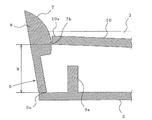
係止片5は、図3に示すように、側面ほぼ包丁状に形成され、上部に設けた係止爪6は、内側が円弧部7(弓形状)に形成されて、上端部6aと下端部6b(係止部)との中間部7a(中央点という)と、下端部6bとのほぼ中間部が最大突出部7bとなっている。
8は他方の短手辺の周壁3に係止片5と対向して内側に向って突設された固定係止片で、その下面は係止片5の係止爪6の係止部6bと同一平面上にあり、固定係止部8aが形成されている。
As shown in FIG. 3, the
9a,9b(以下、単に9と記すことがある)は係止片5及び固定係止片8の内側において、底板2に対向して設けられた支柱で、図3に示すように、係止片5の係止爪6の係止部6bと、支柱9aの上端部との間は、後述のプリント基板の板厚とほぼ等しいか又はこれより僅かに大きい間隔gに形成されている。なお、固定係止片8の係止部8aと、支柱9bの上端部との間隔も同様である。
9a and 9b (hereinafter may be simply referred to as 9) are support columns provided on the inner side of the
次に、上記のように構成した基板ホルダー1へのプリント基板の装着手順の一例について、図4〜図6により説明する。なお、10は多数の電子部品等(図示せず)が搭載されて所定の電子回路が形成され、制御部や表示部などを構成するプリント基板で、その外形は、基板ホルダー1の周壁3の内側とほぼ同じ形状に形成されている。
Next, an example of a procedure for mounting the printed circuit board to the
先ず、図4に示すように、プリント基板10の一方の端部10b(以下、後端部という)を、基板ホルダー1に設けた固定係止片8と支柱9bとの間に差し込み、他方の端部10a(以下、先端部という)を係止片5の係止爪6の円弧部7に当接する。
ついで、プリント基板10の先端部10aを係止爪6の円弧部7に沿って圧下すると、図5に示すように、係止片5を外側に開く(曲がる)力が加わり、係止片5はその基部5aを支点として、弾性変形する。
First, as shown in FIG. 4, one
Next, when the
そして、プリント基板10の先端部10aが係止爪6の最大突出部7bを過ぎると、係止片5は徐々に元の状態に戻り、プリント基板10はその先端部10aが係止爪6の円弧部7を通過して係止爪6から外れると、その下面が支柱9aに当接し、係止片5は元の状態に戻る。
これにより、プリント基板10の先端部10aと後端部10bは、図6に示すように、係止爪6と支柱9a、固定係止片8と支柱9bとの間にそれぞれ挟持され、プリント基板10は、基板ホルダー1の所定の位置に安定して保持される。
And when the front-end |
Thereby, as shown in FIG. 6, the
上記の説明では、基板ホルダー1を長方形の浅い箱状に形成した場合を示したが、これに限定するものではなく、その形状はこれに装着されるプリント基板10の形状に対応して適宜変更することができる。
また、基板ホルダー1を底板2と周壁3とによって形成した場合を示したが、周壁3の一部又は全部に代えて、プリント基板10を位置決めする位置決めピンを設けてもよい。
In the above description, the case where the
Moreover, although the case where the board |
さらに、図には基板ホルダー1の一方の短手辺に係止爪6を有する係止片5を設け、これと対向する他方の短手辺に固定係止片8を設けた場合を示したが、両方とも係止爪6を有する係止片5にしてもよい。
また、係止爪6を有する係止片5や固定係止片8、あるいは支柱9を設ける位置や数は図示のものに限定するものではなく、基板ホルダー1の底板2の周縁部や底板2上の適宜の位置に、適宜数設けてもよい。
Further, the figure shows a case where the
Further, the position and number of the
本実施の形態によれば、係止爪6を有する係止片5、固定係止片8及び支柱9は、すべて基板ホルダー1と一体に設けられているので、基板ホルダー1へのプリント基板10の装着作業性を大幅に向上することができる。
また、係止片5の係止爪6を円弧状に形成したので、プリント基板10の装着初期には係止片5を外側に弾性変形させることができ、最大突出部7bを過ぎると装着方向での係止片5の抵抗がなくなり、係止爪6の円弧部7との摩擦力のみとなるので、プリント基板10を基板ホルダー1に容易に装着することができ、また、装着後は、プリント基板10は元の位置に戻った係止片5の係止爪6及び固定係止片8と、支柱9a,9bとの間に挟持されるので、外れにくい。
According to the present embodiment, since the
Further, since the
さらに、係止片5の係止爪6の最大突出部7bが、係止爪6の下端部6bより上方に位置しているため、係止片5を最大変位させるときの支点5aからの距離hが長いので(図5)、比較的小さい力で係止片5を弾性変形させることができる。
Furthermore, since the
[実施の形態2]
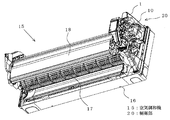
図7は本発明の実施の形態2に係る空気調和機の前面パネルを取外した状態を示す斜視図である。
空気調和機15の筐体16にはファン17や熱交換器18が設けられており、一方の側には制御部20が設けられている。なお、空気の吸込み口、フィルタ、吹出し口、ファン17を駆動するモータ等は図示してない。
[Embodiment 2]
FIG. 7 is a perspective view showing a state where the front panel of the air conditioner according to
The
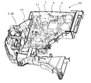
制御部20は、図8に示すように、複雑な平面形状で多数の電子部品等が搭載されて電子回路が形成されたプリント基板10と、このプリント基板10が装着された基板ホルダー1等からなっており、この基板ホルダー1はプリント基板10の平面形状にほぼ対応した複雑な形状の底板2と周壁3とを有し、係止爪6を有する係止片5、固定係止爪8、支柱9が設けられて実施の形態1の基板ホルダー1と同様の機能を備えている。なお、図8には一部の係止片5及び固定係止片8が示してあり、支柱9は図示されていない。
As shown in FIG. 8, the
本実施の形態においても、実施の形態1の場合と同様に、基板ホルダー1にプリント基板10が容易かつ確実に取付けられ、この基板ホルダー1を空気調和機に搭載することができる。なお、図示の空気調和機15及び制御部20はその一例を示すもので、これらは他の構造や形状であってもよい。
Also in the present embodiment, as in the case of the first embodiment, the printed
1 基板ホルダー、2 底板、3 周壁、5 係止片、6 係止爪、6b 係止爪の下端部、7 円弧部、7a 中央点、7b 最大突出部、8 固定係止片、9a,9b 支柱、10 プリント基板、15 空気調和機、20 制御部。
DESCRIPTION OF
Claims (5)
該係止片に設けた係止爪は内側が円弧状に形成され、該円弧状部の上下方向の中央点と下端部との間に前記係止爪の最大突出部を設けたことを特徴とする基板ホルダー。 A bottom plate having a shape substantially corresponding to the planar shape of the printed circuit board to be mounted, a peripheral wall provided at the periphery of the bottom plate, and a locking piece provided with a locking claw at the top and provided independently from the peripheral wall at the periphery of the bottom plate Have
The locking claw provided on the locking piece is formed in an arc shape on the inner side, and the maximum protruding portion of the locking claw is provided between the vertical center point and the lower end portion of the arc-shaped portion. And substrate holder.
Priority Applications (1)
| Application Number | Priority Date | Filing Date | Title |
|---|---|---|---|
| JP2010207085A JP2012064722A (en) | 2010-09-15 | 2010-09-15 | Circuit board holder and air handling unit with circuit board holder |
Applications Claiming Priority (1)
| Application Number | Priority Date | Filing Date | Title |
|---|---|---|---|
| JP2010207085A JP2012064722A (en) | 2010-09-15 | 2010-09-15 | Circuit board holder and air handling unit with circuit board holder |
Publications (2)
| Publication Number | Publication Date |
|---|---|
| JP2012064722A true JP2012064722A (en) | 2012-03-29 |
| JP2012064722A5 JP2012064722A5 (en) | 2012-09-06 |
Family
ID=46060138
Family Applications (1)
| Application Number | Title | Priority Date | Filing Date |
|---|---|---|---|
| JP2010207085A Pending JP2012064722A (en) | 2010-09-15 | 2010-09-15 | Circuit board holder and air handling unit with circuit board holder |
Country Status (1)
| Country | Link |
|---|---|
| JP (1) | JP2012064722A (en) |
Cited By (3)
| Publication number | Priority date | Publication date | Assignee | Title |
|---|---|---|---|---|
| JP2014225488A (en) * | 2013-05-15 | 2014-12-04 | パナソニック株式会社 | Radio substrate fixing structure |
| JP2017058024A (en) * | 2015-09-14 | 2017-03-23 | パナソニックIpマネジメント株式会社 | Air conditioner |
| WO2018100649A1 (en) * | 2016-11-29 | 2018-06-07 | 三菱電機株式会社 | Housing for electronic device |
Citations (9)
| Publication number | Priority date | Publication date | Assignee | Title |
|---|---|---|---|---|
| JPS51130454U (en) * | 1975-04-15 | 1976-10-21 | ||
| JPS58133982U (en) * | 1982-03-04 | 1983-09-09 | 海瀬電気株式会社 | Board mounting structure |
| JPS599587U (en) * | 1982-07-12 | 1984-01-21 | 日本電気株式会社 | Printed board fixed structure |
| JPH04119208A (en) * | 1990-09-05 | 1992-04-20 | Fujitsu Ltd | Substrate fixing structure |
| JPH1154962A (en) * | 1997-08-05 | 1999-02-26 | Mitsubishi Electric Corp | Substrate holder of electrical apparatus |
| JPH11177260A (en) * | 1997-12-15 | 1999-07-02 | Atsumi Electron Corp Ltd | Fixing structure for substrate |
| JP2000077870A (en) * | 1998-09-02 | 2000-03-14 | Pioneer Electronic Corp | Hook |
| JP2002009468A (en) * | 2000-06-23 | 2002-01-11 | Tanita Corp | Printed circuit board mounting structure |
| JP2003229682A (en) * | 2002-02-06 | 2003-08-15 | Keihin Corp | Fixing member for electronic circuit board |
-
2010
- 2010-09-15 JP JP2010207085A patent/JP2012064722A/en active Pending
Patent Citations (9)
| Publication number | Priority date | Publication date | Assignee | Title |
|---|---|---|---|---|
| JPS51130454U (en) * | 1975-04-15 | 1976-10-21 | ||
| JPS58133982U (en) * | 1982-03-04 | 1983-09-09 | 海瀬電気株式会社 | Board mounting structure |
| JPS599587U (en) * | 1982-07-12 | 1984-01-21 | 日本電気株式会社 | Printed board fixed structure |
| JPH04119208A (en) * | 1990-09-05 | 1992-04-20 | Fujitsu Ltd | Substrate fixing structure |
| JPH1154962A (en) * | 1997-08-05 | 1999-02-26 | Mitsubishi Electric Corp | Substrate holder of electrical apparatus |
| JPH11177260A (en) * | 1997-12-15 | 1999-07-02 | Atsumi Electron Corp Ltd | Fixing structure for substrate |
| JP2000077870A (en) * | 1998-09-02 | 2000-03-14 | Pioneer Electronic Corp | Hook |
| JP2002009468A (en) * | 2000-06-23 | 2002-01-11 | Tanita Corp | Printed circuit board mounting structure |
| JP2003229682A (en) * | 2002-02-06 | 2003-08-15 | Keihin Corp | Fixing member for electronic circuit board |
Cited By (3)
| Publication number | Priority date | Publication date | Assignee | Title |
|---|---|---|---|---|
| JP2014225488A (en) * | 2013-05-15 | 2014-12-04 | パナソニック株式会社 | Radio substrate fixing structure |
| JP2017058024A (en) * | 2015-09-14 | 2017-03-23 | パナソニックIpマネジメント株式会社 | Air conditioner |
| WO2018100649A1 (en) * | 2016-11-29 | 2018-06-07 | 三菱電機株式会社 | Housing for electronic device |
Similar Documents
| Publication | Publication Date | Title |
|---|---|---|
| US20060146490A1 (en) | Mounting assembly of computer enclosure | |
| JP2003329024A (en) | Fixing tool | |
| JP5697809B2 (en) | Display module holding structure | |
| US8247707B2 (en) | Shielding assembly | |
| US20080025848A1 (en) | Fixing device for fan | |
| TW201345377A (en) | Expansion module and fixing frame thereof | |
| CN103108518A (en) | Electronic device | |
| JPWO2015033472A1 (en) | Electronics | |
| JP2012064722A (en) | Circuit board holder and air handling unit with circuit board holder | |
| WO2006004153A1 (en) | Electronic device with built-in antenna | |
| US7969726B2 (en) | Fixing mechanism for storage device | |
| JP4403856B2 (en) | Display device | |
| US20130088817A1 (en) | Fixing mechanism and electronic device using the same | |
| US9146581B2 (en) | Hard disk drive mounting device and electronic device using the same | |
| JP2006039361A (en) | Electronic equipment and manufacturing method therefor | |
| JP5523156B2 (en) | In-vehicle display device | |
| CN210324028U (en) | Buckling piece and electronic device comprising same | |
| JP4896634B2 (en) | Parts installation structure | |
| JP2018035965A (en) | Top board of built-in stove | |
| JP2010011720A (en) | Inverter device | |
| JP2009156307A (en) | Fastening device | |
| JP5158192B2 (en) | Electronics | |
| JP2009164497A (en) | Resin case, and motor controller equipped with the same | |
| US20070138115A1 (en) | Holding apparatus for fasteners | |
| JP4641004B2 (en) | PCB mounting structure |
Legal Events
| Date | Code | Title | Description |
|---|---|---|---|
| A521 | Written amendment |
Free format text: JAPANESE INTERMEDIATE CODE: A523 Effective date: 20120720 |
|
| A621 | Written request for application examination |
Free format text: JAPANESE INTERMEDIATE CODE: A621 Effective date: 20120720 |
|
| A977 | Report on retrieval |
Free format text: JAPANESE INTERMEDIATE CODE: A971007 Effective date: 20130619 |
|
| A131 | Notification of reasons for refusal |
Free format text: JAPANESE INTERMEDIATE CODE: A131 Effective date: 20130702 |
|
| A521 | Written amendment |
Free format text: JAPANESE INTERMEDIATE CODE: A523 Effective date: 20130814 |
|
| A131 | Notification of reasons for refusal |
Free format text: JAPANESE INTERMEDIATE CODE: A131 Effective date: 20140204 |
|
| A02 | Decision of refusal |
Free format text: JAPANESE INTERMEDIATE CODE: A02 Effective date: 20140701 |