JP2012061790A - Medium processing apparatus, method for controlling the same, and program - Google Patents
Medium processing apparatus, method for controlling the same, and program Download PDFInfo
- Publication number
- JP2012061790A JP2012061790A JP2010209108A JP2010209108A JP2012061790A JP 2012061790 A JP2012061790 A JP 2012061790A JP 2010209108 A JP2010209108 A JP 2010209108A JP 2010209108 A JP2010209108 A JP 2010209108A JP 2012061790 A JP2012061790 A JP 2012061790A
- Authority
- JP
- Japan
- Prior art keywords
- sensor
- recording unit
- cut sheet
- roll paper
- input
- Prior art date
- Legal status (The legal status is an assumption and is not a legal conclusion. Google has not performed a legal analysis and makes no representation as to the accuracy of the status listed.)
- Pending
Links
Images


Abstract
Description
本発明は、ロール紙や単票紙等の記録媒体に記録等の処理を行う媒体処理装置、当該媒体処理装置の制御方法、及び、当該媒体処理装置を制御するためのプログラムに関する。 The present invention relates to a medium processing apparatus that performs processing such as recording on a recording medium such as roll paper or cut paper, a control method for the medium processing apparatus, and a program for controlling the medium processing apparatus.
従来、ロール紙に記録を行う媒体処理装置(例えば、特許文献1参照)が知られており、また、小切手に記録された磁気インク文字を読み取り可能な装置(例えば、特許文献2参照)において、小切手に対して裏書きに係る画像等を記録可能な媒体処理装置が知られている。 Conventionally, a medium processing apparatus (for example, see Patent Document 1) that records on roll paper is known, and in an apparatus (for example, see Patent Document 2) that can read magnetic ink characters recorded on a check. 2. Description of the Related Art Media processing apparatuses that can record an image or the like related to a check on a check are known.
上述したような媒体処理装置では、各種センサーを備え、これらセンサーの検出値に基づいて、各種動作を実行する。例えば、ロール紙に記録を行う媒体処理装置では、印刷ヘッドの温度検出用のセンサーを設け、このセンサーの検出値に基づいて、印刷ヘッドの駆動を制御し、また、磁気インク文字を読み取り可能な媒体処理装置では、装置本体内における小切手の位置を検出するセンサーを設け、このセンサーの検出値に基づいて、小切手の搬送を制御する。
ここで、ロール紙に記録を行う媒体処理装置と、小切手等の記録媒体に記録を行う媒体処理装置とを、1つの装置として一体化することを想定する。
この場合、センサーの数の増大に伴い、センサーの数に対し、A/Dコンバーター(アナログデジタル変換器)等の信号処理用の回路のポートの数が少ない場合が生じ得る。特に、いずれか一方の媒体処理装置が備えていた既存の信号処理用の回路を使用する場合に、センサーの数に対し、信号処理用の回路のポートの数が少ない場合が生じ得る。この場合、信号処理用の回路を複数設けたり、また、ポートの多い信号処理用の回路を新たに設けたりすることも考えられるが、開発コスト、製造コストの増大を招くという問題がある。
本発明は、上述した事情に鑑みてなされたものであり、ロール紙への記録、及び、単票紙への記録の双方を可能な媒体処理装置において、センサーの数に対し、信号処理用の回路のポートの数が少ない場合に、コストを抑制しつつ、信号処理用の回路に対し、各センサーの検出値を入力することを目的とする。
The medium processing apparatus as described above includes various sensors, and executes various operations based on the detection values of these sensors. For example, in a medium processing apparatus that records on roll paper, a sensor for detecting the temperature of the print head is provided, the drive of the print head is controlled based on the detection value of the sensor, and magnetic ink characters can be read. In the medium processing apparatus, a sensor for detecting the position of the check in the apparatus main body is provided, and the conveyance of the check is controlled based on the detection value of the sensor.
Here, it is assumed that the medium processing apparatus for recording on roll paper and the medium processing apparatus for recording on a recording medium such as a check are integrated as one apparatus.
In this case, with the increase in the number of sensors, there may be a case where the number of ports of a signal processing circuit such as an A / D converter (analog / digital converter) is small with respect to the number of sensors. In particular, when an existing signal processing circuit included in any one of the medium processing apparatuses is used, the number of signal processing circuit ports may be smaller than the number of sensors. In this case, a plurality of signal processing circuits may be provided or a signal processing circuit having many ports may be newly provided. However, there is a problem that the development cost and the manufacturing cost increase.
The present invention has been made in view of the above-described circumstances. In a medium processing apparatus capable of both recording on roll paper and recording on cut sheet paper, the number of sensors is not limited to signal processing. It is an object to input detection values of each sensor to a signal processing circuit while suppressing cost when the number of circuit ports is small.
上記目的を達成するために、本発明は、媒体処理装置であって、ロール紙を搬送して記録を行うロール紙記録部と、単票紙を搬送して記録を行う単票紙記録部と、前記ロール紙記録部の状態を検出するセンサーと、前記単票紙記録部の状態を検出するセンサーと、を備え、信号処理用の回路の入力用の一のポートに対して、前記ロール紙記録部のセンサーと、前記単票紙記録部のセンサーとを含む2以上のセンサーから一のセンサーを選択して入力するものであり、前記ロール紙記録部と前記単票紙記録部とのそれぞれの動作状態に基づき、前記一のポートに入力するセンサーを切り替える切替部を備えることを特徴とする。
この構成によれば、ロール紙記録部、及び、単票紙記録部の動作状態を反映して、ロール紙に記録を行うロール紙記録部の状態を検出するセンサーと、ロール紙とは別の単票紙記録部に記録を行う単票紙記録部の状態を検出するセンサーとを一のポートを介して信号処理用の回路に入力でき、新たに信号処理用の回路を設ける場合と比較して、コストを抑制しつつ、各センサーを信号処理用の回路に入力できる。
In order to achieve the above object, the present invention provides a medium processing apparatus, a roll paper recording unit that conveys and records a roll paper, and a cut sheet recording unit that conveys and records a cut sheet A sensor for detecting the state of the roll paper recording unit, and a sensor for detecting the state of the cut sheet recording unit, and the roll paper with respect to one port for input of a signal processing circuit. One sensor is selected and input from two or more sensors including a sensor of the recording unit and a sensor of the cut sheet recording unit, and each of the roll paper recording unit and the cut sheet recording unit And a switching unit that switches a sensor to be input to the one port based on the operation state.
According to this configuration, the sensor that detects the state of the roll paper recording unit that records on the roll paper, reflecting the operation state of the roll paper recording unit and the cut sheet recording unit, and the roll paper are different. Compared to the case where a sensor for detecting the state of the cut sheet recording unit that records on the cut sheet recording unit can be input to the signal processing circuit through one port, and a new signal processing circuit is provided. Thus, each sensor can be input to a signal processing circuit while suppressing costs.
また、上記発明の媒体処理装置であって、本発明は、前記切替部は、前記一のポートに入力可能なセンサーのうち、検出のタイミングの異なる複数のセンサーの中から、検出のタイミングに応じて、前記一のポートに入力するセンサーを切り替えることを特徴とする。
この構成によれば、各センサーの検出のタイミングを反映して、信号処理用の回路への入力が必要なセンサーへの切り替えが可能となる。
In the medium processing apparatus according to the invention, the switching unit may be configured to respond to a detection timing from a plurality of sensors having different detection timings among sensors that can be input to the one port. Then, the sensor input to the one port is switched.
According to this configuration, it is possible to switch to a sensor that requires input to a signal processing circuit, reflecting the detection timing of each sensor.
また、上記発明の媒体処理装置であって、本発明は、前記ロール紙記録部、及び、前記単票紙記録部のうち一方の記録部が動作している場合は、他方の記録部の動作を停止する構成とし、前記切替部は、前記一のポートに入力するセンサーを、前記ロール紙記録部、及び、前記単票紙記録部のうち動作する側の記録部のセンサーに切り替えることを特徴とする。
この構成によれば、ロール紙記録部、及び、単票紙記録部のうち、動作している記録部のセンサーが信号処理用の回路に入力されることとなり、その入力が必要なセンサーを、信号処理用の回路に入力できる。
Also, in the medium processing apparatus of the above invention, the present invention is directed to the operation of the other recording unit when one of the roll paper recording unit and the cut sheet recording unit is operating. The switching unit switches the sensor input to the one port to the sensor of the operating recording unit of the roll paper recording unit and the cut sheet recording unit. And
According to this configuration, among the roll paper recording unit and the cut sheet recording unit, the sensor of the operating recording unit is input to the signal processing circuit. It can be input to a circuit for signal processing.
また、上記発明の媒体処理装置であって、本発明は、前記ロール紙記録部のセンサーのうちの一つは、前記ロール紙記録部が備える印刷ヘッドの温度検出用のセンサーであり、前記単票紙記録部のセンサーのうちの一つは、前記単票紙記録部が備える印刷ヘッドの温度検出用のセンサーであり、前記切替部は、前記一のポートに入力するセンサーを、前記ロール紙記録部、及び、前記単票紙記録部のうち記録する側の印刷ヘッドの温度検出用センサーに切り替えることを特徴とする。
この構成によれば、ロール紙記録部が備える印刷ヘッドの温度検出用のセンサーと、単票紙記録部が備える印刷ヘッドの温度検出用のセンサーとを一のポートを介して信号処理用の回路に入力でき、新たに信号処理用の回路を設ける場合と比較して、コストを抑制しつつ、各センサーを信号処理用の回路に入力できる。
Further, in the medium processing apparatus according to the invention, in the invention, one of the sensors of the roll paper recording unit is a sensor for detecting a temperature of a print head provided in the roll paper recording unit. One of the sensors of the slip sheet recording unit is a sensor for detecting the temperature of the print head provided in the cut sheet recording unit, and the switching unit connects the sensor input to the one port to the roll paper. It is characterized in that it is switched to a temperature detection sensor of a recording head and a print head on the recording side of the cut sheet recording section.
According to this configuration, the circuit for signal processing includes the sensor for detecting the temperature of the print head included in the roll paper recording unit and the sensor for detecting the temperature of the print head included in the cut sheet recording unit via one port. Each sensor can be input to the signal processing circuit while suppressing the cost as compared with the case where a new signal processing circuit is provided.
また、上記発明の媒体処理装置であって、本発明は、前記ロール紙記録部のセンサーのうちの一つは、前記ロール紙記録部が備える印刷ヘッドの温度検出用のセンサーであり、前記単票紙記録部は、同一の単票紙に記録可能なもので、同時に駆動しない複数の印刷ヘッドを備えており、前記単票紙記録部のセンサーに含まれるセンサーは、複数の印刷ヘッドのそれぞれに備えられた温度検出用のセンサーであり、前記切替部は、前記一のポートに入力するセンサーを、前記ロール紙記録部、及び、前記単票紙記録部のうち記録する側の印刷ヘッドの温度検出用センサーに切り替え、さらに、前記単票紙記録部の印刷ヘッドの温度検出用センサーに切り替える場合は、前記単票紙記録部の複数の印刷ヘッドのうち記録している側の前記印刷ヘッドの温度検出用のセンサーに切り替えることを特徴とする。
この構成によれば、一つのポートを介して、ロール紙記録部が備える印刷ヘッドの温度検出用のセンサー、及び、単票紙記録部が備える複数の印刷ヘッドの温度検出用のセンサーのそれぞれを信号処理用の回路に入力でき、かつ、駆動している印刷ヘッドに係るセンサー、すなわち、信号処理用の回路による処理が必要なものを、信号処理用の回路に入力できる。
Further, in the medium processing apparatus according to the invention, in the invention, one of the sensors of the roll paper recording unit is a sensor for detecting a temperature of a print head provided in the roll paper recording unit. The slip sheet recording unit is capable of recording on the same cut sheet paper, and includes a plurality of print heads that are not driven simultaneously, and the sensors included in the sensor of the cut sheet recording unit include a plurality of print heads. The temperature detection sensor provided in the switch, wherein the switching unit includes a sensor that inputs to the one port, the roll paper recording unit, and the cut sheet recording unit of the print head on the recording side. When switching to a temperature detection sensor, and further switching to a temperature detection sensor for the print head of the cut sheet recording unit, the print head on the recording side among a plurality of print heads of the cut sheet recording unit. And it switches to the sensor for detecting the temperature.
According to this configuration, the temperature detection sensor of the print head provided in the roll paper recording unit and the temperature detection sensor of the plurality of print heads provided in the cut sheet recording unit are respectively connected through one port. Sensors that can be input to the signal processing circuit, and that require processing by the signal processing circuit, that is, a sensor associated with the driving print head, can be input to the signal processing circuit.
また、上記発明の媒体処理装置であって、本発明は、動作モードとして、前記媒体処理装置内で、前記単票紙を搬送しつつ、前記単票紙記録部により当該単票紙に記録する動作モードと、前記媒体処理装置内の所定の位置に前記単票紙を挿入した状態を維持しつつ、前記単票紙記録部により当該単票紙にバリデーション印刷する動作モードと、を備え、前記媒体処理装置内で搬送される前記単票紙の位置を検出する複数の位置検出センサーと、前記単票紙が前記所定の位置に挿入されたことを検出するバリデーションセンサーと、を備え、前記一のポートに入力可能な複数のセンサーは、前記バリデーションセンサーと前記信号処理用の回路が実装された基板に備えられた温度検出用のセンサーとを少なくとも含み、又は、前記バリデーションセンサーと複数の前記位置検出センサーのいずれか1つのセンサーとを少なくとも含み、又は、前記信号処理用の回路が実装された基板の温度検出用のセンサーと複数の前記位置検出センサーのいずれか1つのセンサーとを少なくとも含むことを特徴とする。
ここで、複数の位置検出センサーのいずれか1つのセンサーは、他の位置検出センサーによる単票紙の位置検出が可能であるため、比較的、検出周期が長いと言える。また、バリデーションセンサーは、単票紙が挿入されたことを確実に検出できればよく、検出の迅速性は強く要求されないため、他のセンサーと比較して検出周期が長いと言える。また、前記信号処理用の回路が実装された基板の温度検出用のセンサーは、当該基板の温度が急激に昇降することはないため、他のセンサーと比較して検出周期が長いと言える。これを踏まえ、上記構成によれば、他のポートを介して入力される複数のセンサーを、検出周期の長いセンサーの組み合わせとすることができる。ここで、信号処理用の回路に入力するセンサーを切り替えることにより、複数のセンサーから信号処理用の回路に入力する場合、センサーの切り替えに伴い、各センサーについて、信号処理用の回路に入力されない時間帯が生じる。そして、上記構成によれば、一つのポートに対して、他のセンサーと比較して検出周期が長い複数のセンサーを入力可能な構成とすることにより、上記時間帯が生じることによる悪影響を抑制できる。
Further, in the medium processing apparatus according to the invention described above, the present invention records, as an operation mode, on the cut sheet paper by the cut sheet recording unit while conveying the cut sheet in the medium processing apparatus. An operation mode, and an operation mode for performing validation printing on the cut sheet by the cut sheet recording unit while maintaining the state where the cut sheet is inserted at a predetermined position in the medium processing apparatus, and A plurality of position detection sensors for detecting the position of the cut sheet conveyed in the medium processing apparatus, and a validation sensor for detecting that the cut sheet has been inserted into the predetermined position. The plurality of sensors that can be input to the port include at least the validation sensor and a temperature detection sensor provided on a substrate on which the signal processing circuit is mounted, or the validation sensor A sensor and at least one of the plurality of position detection sensors, or any one of a sensor for detecting a temperature of a substrate on which the signal processing circuit is mounted and a plurality of the position detection sensors. And at least a sensor.
Here, since any one of the plurality of position detection sensors can detect the position of the cut sheet by the other position detection sensors, it can be said that the detection cycle is relatively long. The validation sensor only needs to be able to reliably detect that the cut sheet has been inserted, and since the rapid detection is not required, it can be said that the detection cycle is longer than that of other sensors. In addition, it can be said that the sensor for detecting the temperature of the substrate on which the circuit for signal processing is mounted has a longer detection cycle than other sensors because the temperature of the substrate does not rise or fall rapidly. Based on this, according to the above configuration, a plurality of sensors input via other ports can be combined with sensors having a long detection cycle. Here, when switching from a plurality of sensors to the signal processing circuit by switching the sensor input to the signal processing circuit, the time when each sensor is not input to the signal processing circuit as the sensor is switched A band is formed. And according to the said structure, the bad influence by the said time slot | zone arising can be suppressed by setting it as the structure which can input several sensors with a long detection period compared with another sensor with respect to one port. .
また、上記発明の媒体処理装置であって、本発明は、前記信号処理用の回路の他のポートに対して、他のセンサーと比較して検出周期が長い複数のセンサーを入力可能な構成としたことを特徴とする。
ここで、信号処理用の回路に入力するセンサーを切り替えることにより、複数のセンサーから信号処理用の回路に入力する場合、センサーの切り替えに伴い、各センサーについて、信号処理用の回路に入力されない時間帯が生じる。そして、上記構成によれば、一つのポートに対して、他のセンサーと比較して検出周期が長い複数のセンサーを入力可能な構成とすることにより、上記時間帯が生じることによる悪影響を抑制できる。
Further, in the medium processing apparatus according to the above invention, the present invention has a configuration in which a plurality of sensors having a detection cycle longer than that of other sensors can be input to another port of the signal processing circuit. It is characterized by that.
Here, when switching from a plurality of sensors to the signal processing circuit by switching the sensor input to the signal processing circuit, the time when each sensor is not input to the signal processing circuit as the sensor is switched A band is formed. And according to the said structure, the bad influence by the said time slot | zone arising can be suppressed by setting it as the structure which can input several sensors with a long detection period compared with another sensor with respect to one port. .
また、上記目的を達成するために、本発明は、ロール紙を搬送して記録を行うロール紙記録部と、単票紙を搬送して記録を行う単票紙記録部と、前記ロール紙記録部の状態を検出するセンサーと、前記単票紙記録部の状態を検出するセンサーと、を備える媒体処理装置を制御して、信号処理用の回路の入力用の一のポートに対して、前記ロール紙記録部のセンサーと、前記単票紙記録部のセンサーとを含む2以上のセンサーから一のセンサーを選択して入力するように、前記ロール紙記録部と前記単票紙記録部とのそれぞれの動作状態に基づき、前記一のポートに入力するセンサーを切り替え、切り替えられた一のセンサーを前記信号処理用の回路に入力することを特徴とする。
この制御方法によれば、ロール紙に記録を行うロール紙記録部のセンサーと、ロール紙とは別の単票紙記録部に記録を行う単票紙記録部のセンサーとを一のポートを介して信号処理用の回路に入力でき、新たに信号処理用の回路を設ける場合と比較して、コストを抑制しつつ、各センサーを信号処理用の回路に入力できる。
In order to achieve the above object, the present invention includes a roll paper recording unit that conveys and records roll paper, a single sheet recording unit that conveys and records cut paper, and the roll paper recording A medium processing device comprising: a sensor for detecting a state of the unit; and a sensor for detecting the state of the cut sheet recording unit, and for one port for input of a signal processing circuit, The roll paper recording unit and the cut sheet recording unit are configured to select and input one sensor from two or more sensors including a sensor of the roll paper recording unit and a sensor of the cut sheet recording unit. The sensor input to the one port is switched based on each operation state, and the switched one sensor is input to the signal processing circuit.
According to this control method, the sensor of the roll paper recording unit that records on the roll paper and the sensor of the single sheet paper recording unit that records on the single sheet paper recording unit different from the roll paper are connected via one port. Thus, each sensor can be input to the signal processing circuit while suppressing the cost as compared with a case where a new signal processing circuit is provided.
また、上記目的を達成するために、本発明は、ロール紙を搬送して記録を行うロール紙記録部と、単票紙を搬送して記録を行う単票紙記録部と、前記ロール紙記録部の状態を検出するセンサーと、前記単票紙記録部の状態を検出するセンサーと、を備え、信号処理用の回路の入力用の一のポートに対して、前記ロール紙記録部のセンサーと、前記単票紙記録部のセンサーとを含む2以上のセンサーから一を選択して入力するように媒体処理装置を制御する制御部により実行されるプログラムであって、前記制御部を、前記ロール紙記録部と前記単票紙記録部とのそれぞれの動作状態に基づき、前記一のポートに入力するセンサーを切り替える切替部として動作させることを特徴とする。
このプログラムを実行すれば、ロール紙に記録を行うロール紙記録部のセンサーと、ロール紙とは別の単票紙記録部に記録を行う単票紙記録部のセンサーとを一のポートを介して信号処理用の回路に入力でき、新たに信号処理用の回路を設ける場合と比較して、コストを抑制しつつ、各センサーを信号処理用の回路に入力できる。
In order to achieve the above object, the present invention includes a roll paper recording unit that conveys and records roll paper, a single sheet recording unit that conveys and records cut paper, and the roll paper recording A sensor for detecting the state of the copy section, and a sensor for detecting the state of the cut sheet recording unit, and the sensor of the roll sheet recording unit for one port for input of the signal processing circuit; , A program executed by a control unit that controls the medium processing apparatus so as to select and input one of two or more sensors including a sensor of the cut sheet recording unit, the control unit including the roll Based on respective operation states of the paper recording unit and the cut sheet recording unit, the sheet recording unit is operated as a switching unit that switches a sensor input to the one port.
When this program is executed, the sensor of the roll paper recording unit that records on the roll paper and the sensor of the single sheet paper recording unit that records on the single sheet paper recording unit different from the roll paper are connected via one port. Thus, each sensor can be input to the signal processing circuit while suppressing the cost as compared with a case where a new signal processing circuit is provided.
本発明によれば、ロール紙への記録、及び、当該ロール紙以外の記録媒体への記録の双方を可能な記録装置において、センサーの数に対し、信号処理用の回路のポートの数が少ない場合に、コストを抑制しつつ、信号処理用の回路に対し、各センサーを入力できる。 According to the present invention, in a recording apparatus capable of both recording on roll paper and recording on a recording medium other than the roll paper, the number of signal processing circuit ports is smaller than the number of sensors. In this case, each sensor can be input to the signal processing circuit while suppressing the cost.
以下、図面を参照して本発明の実施形態について説明する。
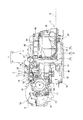
図1は、本実施形態に係る媒体処理装置としての複合処理装置を示す外観斜視図である。複合処理装置(媒体処理装置)1は、小切手(単票紙)Sに記録されている磁気インク文字(MICR(Magnetic Ink Character Recognition)文字ともいう)を読み取り、その内容に応じて小切手に印刷(記録)処理を行う。また、複合処理装置1は、感熱紙をロール形状に巻き回したロール紙Rを内部に収容し、このロール紙に対して印刷(記録)処理を行う。
複合処理装置1は、図1に示すように、全体として直方体形状をした本体ケース2を備え、この本体ケース2の前面の左側寄りの部分には、小切手Sを挿入するための媒体挿入口3が装置幅方向に沿って所定幅で設けられている。本体ケース2の上面の装置前後方向の中央部分には、処理された小切手Sが排出される媒体排出口4が装置幅方向に沿って所定幅で設けられている。媒体挿入口3と媒体排出口4との間には、媒体挿入口3から装置後方に延びた後に上方に湾曲して延びる媒体搬送路5が形成されている。これら媒体挿入口3、媒体排出口4及び媒体搬送路5は、本体ケース2の左側面を開放して形成されており、当該媒体挿入口3、媒体排出口4及び媒体搬送路5よりも幅の広い小切手Sを搬送することが可能となっている。
Hereinafter, embodiments of the present invention will be described with reference to the drawings.
FIG. 1 is an external perspective view showing a composite processing apparatus as a medium processing apparatus according to the present embodiment. The composite processing device (medium processing device) 1 reads magnetic ink characters (also referred to as MICR (Magnetic Ink Character Recognition) characters) recorded on a check (sheet paper) S and prints them on the check according to the contents ( Record) processing. In addition, the
As shown in FIG. 1, the
本体ケース2の上面において、媒体排出口4よりも前側は前側カバー6によって被われており、前側カバー6の前端部分には複合処理装置1の各種操作を行う操作パネル7が設けられている。また、本体ケース2の上面には、媒体排出口4よりも後側に印刷処理されたロール紙Rが排出されるロール紙排出口8が装置幅方向に沿って所定幅で設けられている。本体ケース2の上面において、ロール紙排出口8よりも後側には開閉蓋9が設けられ、この開閉蓋9は、後端を中心として回動可能に本体ケース2に取り付けられている。開閉蓋9を開くと、ロール紙Rを収納するロール紙収容部10が露出し、ロール紙Rの交換を行うことができる。ロール紙Rは、長尺の感熱紙を芯管にロール状に巻きつけて構成されている。
On the upper surface of the
図2は、複合処理装置1の装置本体を示す概略側面図である。図2は本体ケース2、前側カバー6および開閉蓋9などの外装部品を取り除いた状態を示している。複合処理装置1は、図2に示すように、装置本体11を備え、この装置本体11は、小切手Sに印刷処理を行うスリップ印刷部12と、ロール紙Rに印刷処理を行うロール紙印刷部13とを一体に備えて構成されている。スリップ印刷部12は、単票紙たる小切手Sに記録を行うロール紙記録部として機能し、ロール紙印刷部13は、ロール紙に記録を行うロール紙記録部として機能する。
ロール紙印刷部13は、左右一対の左サイドフレーム14及び右サイドフレーム(不図示)と、これらサイドフレーム間に設けられてロール紙収容部10の床面、前面及び背面を形成するロール紙ホルダー(不図示)を備える。このロール紙ホルダーは、ロール紙Rを回転自在に保持し、ロール紙収容部10でロール紙Rが自由に転動することを確保している。
FIG. 2 is a schematic side view showing the apparatus main body of the
The roll
左右のサイドフレーム間には、ロール紙排出口8の近傍に、プラテンローラー15が回転自在に掛け渡されている。プラテンローラー15の前方には、当該プラテンローラー15に対向する位置にサーマルヘッド16が配置されており、このサーマルヘッド16は、プラテンローラー15との対向面に複数の発熱抵抗体を備えている。ロール紙収容部10に収納されたロール紙Rの先端部分は、プラテンローラー15とサーマルヘッド16とで挟持され、プラテンローラー15が回転することによりロール紙排出口8へと送られる。そして、プラテンローラー15とサーマルヘッド16との間を通過する際に、サーマルヘッド16が発熱することにより文字や画像がロール紙Rに記録される。左サイドフレーム14には、ロール紙搬送モーター17が配置され、このロール紙搬送モーター17の回転が中間ギア18を介してプラテンローラー15と同軸上に形成される駆動ギア19に伝達され、プラテンローラー15が回転する。
また、プラテンローラー15の上方には、可動刃20及びこの可動刃20を進退させるカッター駆動モーター24(図4参照)を内蔵したオートカッターユニット21が配置されており、このオートカッターユニット21の後方には、ロール紙排出口8を挟んで、固定刃22が設けられている。ロール紙Rの先端部分は、可動刃20と固定刃22との間を通ってロール紙排出口8に延びており、ロール紙Rを切断する際には、カッター駆動モーター24の駆動により可動刃20が固定刃22に向かって後方に遥動し、固定刃22と協働してロール紙Rを切断する。
さらに、左サイドフレーム14には、ロール紙収容部10内のロール紙Rの残量を検知するロール紙残量センサー23が設けられている。
Between the left and right side frames, a platen roller 15 is rotatably spanned in the vicinity of the roll paper discharge port 8. A
Further, above the platen roller 15, there is disposed an
Further, the
スリップ印刷部12は、図2に示すように、ベースフレーム31と、このベースフレーム31に立設された左サイドフレーム32及び右サイドフレーム(不図示)とを有する本体フレーム33を備える。この本体フレーム33には下案内面35及び上案内面36を構成する上下一対の紙案内部材が設けられ、下案内面35と上案内面36との隙間が上述した媒体搬送路5として形成されている。この媒体搬送路5は、媒体挿入口3から装置後方に延びる水平搬送路部分5aと、この水平搬送路部分5aの後端から上方に湾曲する湾曲搬送路部分5bと、この湾曲搬送路部分5bの上端から上方に延びて媒体排出口4に連なる垂直搬送路部分5cとを備える。
As shown in FIG. 2, the
水平搬送路部分5aと湾曲搬送路部分5bとの境界部分には、一対の第1搬送ローラー34が下案内面35及び上案内面36にそれぞれ対向配置され、垂直搬送路部分5cには、一対の第2搬送ローラー37が下案内面35及び上案内面36にそれぞれ対向配置されている。これら第1搬送ローラー34及び第2搬送ローラー37は、それぞれスリップ搬送モーター38(図4)の駆動により回転して小切手Sを搬送する。また、第1搬送ローラー34及び第2搬送ローラー37は、それぞれ一方のローラー部材が他方のローラー部材に対して進退自在に構成されるとともに、当該一方のローラー部材に連結されるローラー開閉モーター39(図4)の駆動に応じた進退動作により媒体搬送路5を開閉する。また、ベースフレーム31上には、制御プログラムに基づいて複合処理装置1全体の動作を制御する制御基板40が配置されている。
A pair of
図3は、媒体搬送路に設けられた各部材を示す模式図である。
媒体搬送路5上には、媒体挿入口3側から順にBOF(Bottom of Form)センサー41、MICRヘッド42、第1搬送ローラー34、TOF(Top of Form)センサー43、整列手段44、バリデーションセンサー45、第1印刷ヘッド(記録ヘッド)46、MOP(Middle of Paper pass)センサー47(位置検出センサー)、第2搬送ローラー37、第2印刷ヘッド48、EJD(Slip Eject Detector)センサー49が設けられている。
FIG. 3 is a schematic diagram illustrating each member provided in the medium conveyance path.
A BOF (Bottom of Form)
BOFセンサー41、TOFセンサー43、バリデーションセンサー45、MOPセンサー47及びEJDセンサー49は、例えば透過型もしくは反射型のフォトセンサーで構成されており、媒体搬送路5の各位置で小切手Sの有無を非接触で検出するものである。
BOFセンサー41は、媒体挿入口3から挿入された小切手Sの後端を検出するものであり、媒体挿入口3近傍の下案内面35に設けられている。TOFセンサー43は、媒体挿入口3から挿入された小切手Sの先端を検出するものであり、第1搬送ローラー34よりも媒体排出口側近傍の上案内面36に設けられている。EJDセンサー49は、スリップ印刷部12で処理された小切手Sが媒体排出口4から排出されたことを検出するものであり、この媒体排出口4近傍に設けられている。MOPセンサー47は、媒体搬送路5を搬送される小切手Sの有無を検出するものであり、第2搬送ローラー37よりも媒体挿入口側近傍の上案内面36に設けられている。
The
The
本実施形態のスリップ印刷部12は、小切手Sを媒体排出口4から挿入して第1印刷ヘッド46及び第2印刷ヘッド48により印刷を行い、印刷後に再び媒体排出口4から小切手Sを排出するバリデーション印刷を行うことが可能に構成されている。このため、媒体搬送路5の湾曲搬送路部分5bの上端には、媒体排出口4から挿入される小切手Sの先端が進入し、当該小切手Sを整列するための凹部50が形成されている。バリデーションセンサー45は、小切手Sの先端が凹部50に進入したことを検出するものであり、この凹部50に対向する位置に設けられている。
The
MICRヘッド42は、小切手Sの表面に記録された磁気インク文字の読取処理を行うためのものであり、媒体搬送路5の水平搬送路部分5aにおける上案内面36に設けられている。このMICRヘッド42にて読み取られたデータに基づいて小切手Sの有効・無効が判断される。整列手段44は、媒体挿入口3から挿入された小切手Sを一旦停止させるためのものであり、TOFセンサー43よりも媒体排出口側の近傍位置に設けられている。整列手段は、例えばソレノイド等のストッパー駆動部44aと、このストッパー駆動部44aの動作に応じて、媒体搬送路5内に進退するストッパー部材44bとを備え、このストッパー部材44bに小切手Sの先端が当接することで小切手Sが整列される。
The
第1印刷ヘッド46は、媒体搬送路5を搬送される小切手Sの裏面に、買い物客の認証番号、日付、使用金額等の店側として必要な裏書き事項を印刷するためのもので、インクリボンに記録ワイヤーを打ち当ててインクリボンのインクを付着させて印刷するシリアル・インパクト・ドット・マトリクス(SIDM)印刷ヘッドとして構成されている。この第1印刷ヘッド46は、媒体搬送路5の垂直搬送路部分5cの下端部に位置し、この垂直搬送路部分5cを挟んで当該第1印刷ヘッド46と対向する位置には本体フレーム33(図2)の幅方向に亘って第1プラテン51が設けられている。また、第1印刷ヘッド46は、垂直搬送路部分5cよりも装置後側に配置される第1キャリッジ52に搭載される。この第1キャリッジ52は、本体フレーム33(図2)のサイドフレーム間に略水平に掛け渡された第1キャリッジ軸53に摺動自在に設けられ、第1キャリッジ駆動モーター(駆動手段:図4)54の駆動により、第1キャリッジ軸53に沿って往復移動する。第1キャリッジ52は、タイミングベルト(不図示)を介して、第1キャリッジ駆動モーター54と連結されている。この第1キャリッジ駆動モーター54は、ステッピングモーターで構成されており、制御基板40の制御下、第1キャリッジ52を所望のステップに相当する距離だけ移動させることができる。
また、第1キャリッジ52の下部には、この第1キャリッジ52の位置検出を行う第1キャリッジセンサー55が設けられている。この第1キャリッジセンサー55は、透過型のフォトセンサーであり、第1キャリッジ52の往復移動に伴って、第1キャリッジ軸53と略平行に設けられた第1スケール56を走査する。この第1スケール56には、所定幅のスリットが複数形成されており、第1キャリッジセンサー55が第1スケール56を走査する際に、これらスリットを通過する光信号を取得することにより、第1キャリッジ52の変位量を検出して当該第1キャリッジ52(第1印刷ヘッド46)の位置検出を行う。なお、本実施形態では、第1キャリッジセンサー55には、第1キャリッジ駆動モーター54の駆動中にのみ電源が供給されるようになっており、第1キャリッジ駆動モーター54が停止した際には第1キャリッジセンサー55への電源供給が遮断されるため、待機電力の消費量が減少し、省エネルギー化を図ることができる。
The
A
第2印刷ヘッド48は、媒体搬送路5を搬送される小切手Sの表面に、支払い先、日付、金額等の表書き事項を印刷するためのもので、第1印刷ヘッド46と同様にSIDM印刷ヘッドとして構成されている。この第2印刷ヘッド48は、第1印刷ヘッド46よりも上方であって、垂直搬送路部分5cを挟んだ装置前側に配置されている。また、垂直搬送路部分5cを挟んで当該第2印刷ヘッド48と対向する位置には本体フレーム33(図2)の幅方向に亘って第2プラテン57が設けられている。第2印刷ヘッド48は、上記第1印刷ヘッド46と同様に、第2キャリッジ58に搭載され、この第2キャリッジ58は、第2キャリッジ駆動モーター59の駆動により、第2キャリッジ軸60に沿って往復移動する。また、第2キャリッジ58の下部には第2キャリッジセンサー61が設けられ、この第2キャリッジセンサー61は、第2キャリッジ58の往復移動に伴って、第2キャリッジ軸60と略平行に設けられた第2スケール62を走査する。なお、第2キャリッジ駆動モーター59も第1キャリッジ駆動モーター54と同様にステッピングモーターとして構成されている。
The
また、本体フレーム33には、第1印刷ヘッド46と第1プラテン51との間、及び、第2印刷ヘッド48と第2プラテン57との間にそれぞれ繰り出されるインクリボンを収容した第1インクリボンカセット63(図2)及び第2インクリボンカセット64(図2)が着脱可能な状態で装着されている。
The main body frame 33 includes a first ink ribbon cassette that stores ink ribbons fed between the
図4は、複合処理装置1の機能的構成を示すブロック図である。
この図4に示すように、複合処理装置1の制御系は、制御基板40に実装された制御部に、各種モーター等の駆動部及び各種センサーが接続された構成となっている。
制御基板40には、制御プログラムを実行して各部を制御するCPU101、CPU101によって実行されるプログラムや処理されるデータ等を一時的に格納するRAM103、CPU101によって実行される基本制御プログラムや、各種設定値を記憶するフラッシュROM105、複合処理装置1の外部装置としてのホストコンピューター200との間でコマンドやデータ等を送受信する通信インターフェイス107、A/Dコンバーター108を内蔵し、複合処理装置1の各種センサーの検出値をデジタルデータに変換してCPU101に出力するセンサー駆動回路109、複合処理装置1が備える印刷ヘッドを駆動するヘッド駆動回路111、及び、複合処理装置1が備える各モーターを駆動するモータードライバー113を備えて構成され、これらの各部は相互に通信可能に接続されている。なお、制御基板40が備える各機能部は各々が独立した半導体デバイスとして実装されていてもよいし、複数の機能部の機能がSOC(System-on-a-chip)等の形態で統合された構成としてもよく、具体的な実装形態は任意である。
FIG. 4 is a block diagram showing a functional configuration of the
As shown in FIG. 4, the control system of the
The
制御基板40には、モータードライバー113の温度を検出する基板温度センサー115が実装されている。基板温度センサー115は、制御基板40においてモータードライバー113が実装された裏面またはモータードライバー113の近傍に配置されるサーミスターである。
さらに、CPU101には、ロール紙収容部10(図1)に収容されたロール紙Rの残量が所定以上あるか否かを検出するロール紙残量センサー23、開閉蓋9が開いたことを検出するカバー開閉センサー117、上述した第1キャリッジセンサー55及び第2キャリッジセンサー61が接続される。ロール紙残量センサー23は、ロール紙Rの外径が所定以上の場合にオンとなるスイッチ式のセンサーであり、カバー開閉センサー117は、開閉蓋9が開かれるとオンとなるスイッチ式のセンサーであり、それぞれオン/オフ状態に対応してHigh/Loの出力値を出力する。第1キャリッジセンサー55及び第2キャリッジセンサー61は、例えばフォトインターラプターとして構成され、受光部における受光量が内蔵するしきい値を超えるか否かにより出力値をHigh/Loに切り替える。
A
Further, the
CPU101は、フラッシュROM105に記憶された基本制御プログラムを読み出して実行することにより、制御基板40に実装された各部を制御する。また、CPU101は、センサー駆動回路109を介して入力される各種センサーの検出値、及び、ロール紙残量センサー23、カバー開閉センサー117、第1キャリッジセンサー55、及び第2キャリッジセンサー61の出力値に基づいて、複合処理装置1の動作状態を監視し、ヘッド駆動回路111によって各ヘッドを駆動するとともに、モータードライバー113によって各モーターを動作させ、小切手Sの表面および裏面への印刷、MICR読み取り、ロール紙Rへの印刷等の動作を実行する。
The
RAM103は、CPU101の動作時にプログラムやデータ等を一時的に格納するワークエリアを形成する。また、RAM103には、通信インターフェイス107によりホストコンピューター200から受信したコマンドやデータを一時的に記憶する受信バッファー104が設けられる。CPU101は、受信バッファー104に格納されたコマンドを、受信順に読み出して実行する。
センサー駆動回路109は、BOFセンサー41、TOFセンサー43、バリデーションセンサー45、MOPセンサー47、EJDセンサー49、及び基板温度センサー115の各センサーに接続され、これら各センサーの出力値をデジタルデータに変換して、CPU101に出力する。また、センサー駆動回路109はMICRヘッド42に接続され、小切手Sに形成された磁気インク文字をMICRヘッド42によって読み取る動作中、MICRヘッド42の出力値をデジタルデータとしてCPU101に出力する。
さらに、センサー駆動回路109には、第1印刷ヘッド温度センサー75、第2印刷ヘッド温度センサー76、及びサーマルヘッド温度センサー77が接続されている。第1印刷ヘッド温度センサー75は第1印刷ヘッド46に搭載され、第2印刷ヘッド温度センサー76は第2印刷ヘッド48に搭載される。第1印刷ヘッド温度センサー75、第2印刷ヘッド温度センサー76は、記録ワイヤーを突出させるためのソレノイドの近傍に設置され、このソレノイド及びその近傍の温度を検出する。また、サーマルヘッド温度センサー77はサーマルヘッド16の発熱素子の近傍に設置され、この発熱素子の温度を検出する。これら第1印刷ヘッド温度センサー75、第2印刷ヘッド温度センサー76及びサーマルヘッド温度センサー77は、例えばサーミスターで構成され、センサー駆動回路109は、これら第1印刷ヘッド温度センサー75、第2印刷ヘッド温度センサー76及びサーマルヘッド温度センサー77の出力値をデジタルデータとしてCPU101に出力する。CPU101は、第1印刷ヘッド温度センサー75、第2印刷ヘッド温度センサー76及びサーマルヘッド温度センサー77の出力値に基づいて求められる温度をもとに、サーマルヘッド16、第1印刷ヘッド46及び第2印刷ヘッド48を制御する。具体的には、CPU101は、サーマルヘッド16、第1印刷ヘッド46及び第2印刷ヘッド48の温度があらかじめ設定されたしきい値を超えた場合に、そのヘッドの動作を強制的に一時停止させる。この場合、CPU101は、停止させたヘッドの温度が設定値より低くなった場合に動作を再開させる。
The
The
Further, a first print
ヘッド駆動回路111は、CPU101の制御に従って、第1印刷ヘッド46及び第2印刷ヘッド48の各々に対し、記録ワイヤーを突出させるソレノイドコイルに通電することで、小切手Sへの記録を実行させる。また、ヘッド駆動回路111は、CPU101の制御に従ってサーマルヘッド16が備える発熱素子(図示略)に通電して、ロール紙Rの記録面に熱を与えて記録を行う。
モータードライバー113は、ステッピングモーターとして構成されるロール紙搬送モーター17、カッター駆動モーター24、スリップ搬送モーター38、ローラー開閉モーター39、ストッパー駆動部44a、第1キャリッジ駆動モーター54、及び第2キャリッジ駆動モーター59の各モーターに対し、CPU101の制御に従って、駆動電源、及び、駆動パルスを出力する。モータードライバー113が各モーターに供給する駆動電源は、電源ユニット120が各部に供給する24Vの直流電源である。
電源ユニット120は、図4に示す複合処理装置1の各駆動部、すなわち各印刷ヘッド(第1印刷ヘッド46、第2印刷ヘッド48、サーマルヘッド16)、各モーター(カッター駆動モーター24、第1キャリッジ駆動モーター54、第2キャリッジ駆動モーター59、スリップ搬送モーター38、ロール紙搬送モーター17、ローラー開閉モーター39)、ストッパー駆動部44a、および、制御基板40に直流電源を供給する。また、複合処理装置1が備える各センサーに対しては、制御基板40を介して、或いは制御基板40に実装されたセンサー駆動回路109を介して、電源ユニット120からの電源が供給される。
電源ユニット120の出力電圧はセンサー駆動回路109に入力されており、センサー駆動回路109は電源ユニット120の電源電圧の電圧値をデジタルデータとしてCPU101に出力する。CPU101は、このデジタルデータに基づいて電源ユニット120の電圧が正常範囲内か否かを判別する。
The
The
The
The output voltage of the
このように、複合処理装置1は、小切手Sに対してMICR読み取り及び印刷を実行可能であり、ロール紙Rに対して印刷を実行可能である。このうち、制御基板40の制御によって小切手Sを処理するスリップ搬送モーター38、ローラー開閉モーター39、整列手段44、第1印刷ヘッド46、第2印刷ヘッド48、第1キャリッジ駆動モーター54、及び第2キャリッジ駆動モーター59の各動作部を、スリップ動作部とする。このスリップ動作部は、スリップ印刷部12を含んでいてもよい。また、ロール紙Rを処理するサーマルヘッド16、ロール紙搬送モーター17、及びカッター駆動モーター24の各動作部を、ロール紙動作部とする。このロール紙動作部は、上記のロール紙印刷部13を含んでもよい。
As described above, the
続いて、複合処理装置1の動作について説明する。以下に説明する動作はCPU101がフラッシュROM105に記憶されたプログラムを実行することにより、実現される。
複合処理装置1は、電源投入後に待機状態に移行する。この待機状態では、ローラー開閉モーター39によって第1搬送ローラー34及び第2搬送ローラー37を開位置に移動させて、媒体挿入口3に小切手Sを挿入可能とする。また、ストッパー駆動部44aによってストッパー部材44bを媒体搬送路5内に進出させる。この待機状態で小切手Sの挿入を検出すると、CPU101は図5に示すように小切手Sの処理を実行する。また、待機状態でロール紙Rの処理を指示するコマンドをホストコンピューター200から受信すると、CPU101は図6に示すようにロール紙Rの処理を実行する。また、CPU101は、待機状態において小切手Sが媒体排出口4から挿入されたことを検出すると、図7に示すようにバリデーション印刷を実行する。
Next, the operation of the
The
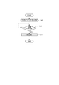
図5は、複合処理装置1の動作を示すフローチャートであり、詳細には、小切手処理に係る通常動作を示す。
上記の待機状態において、CPU101は、媒体挿入口3からの小切手Sの挿入に対して待機する(ステップS11)。CPU101は、センサー駆動回路109から入力されるBOFセンサー41の出力値に基づいて、この小切手Sを検出すると(ステップS11;Yes)、モータードライバー113を制御し、ローラー開閉モーター39を駆動して第1搬送ローラー34及び第2搬送ローラー37を閉位置に移動させて、これら第1搬送ローラー34によって小切手Sを挟持する(ステップS12)。CPU101は、ストッパー部材44bが媒体搬送路5に進出した状態で、スリップ搬送モーター38を動作させて第1搬送ローラー34を回転駆動し、小切手Sを往復搬送する動作を複数回行う(ステップS13)。この動作により、小切手Sはストッパー部材44bに突き当てられてその向きが整う。
FIG. 5 is a flowchart showing the operation of the
In the standby state, the
ここで、CPU101はBOFセンサー41の出力値に基づいて小切手Sの有無を検出し(ステップS14)、小切手Sが検出されない場合は誤操作または小切手Sが引き抜かれたものと判定して本処理を終了する。
一方、BOFセンサー41により小切手Sを検出した場合(ステップS14;Yes)、CPU101は、ストッパー駆動部44aを駆動してストッパー部材44bを媒体搬送路5から退避させる(ステップS15)。続いてCPU101は、第1搬送ローラー34によって小切手Sを搬送し、この間のMICRヘッド42の出力値に基づき、小切手Sの磁気インク文字を読み取る(ステップS16)。CPU101は、ホストコンピューター200から受信したコマンドにより小切手Sの裏面への印刷が指示されると、小切手Sにおける印刷位置に合わせてスリップ搬送モーター38を正転させて媒体搬送路5の下流側へ搬送し、或いは、スリップ搬送モーター38を逆転させて小切手Sを上流側へ搬送することで、印刷位置まで小切手Sを搬送し(ステップS17)、第1印刷ヘッド46によって小切手Sに印刷する(ステップS18)。
Here, the
On the other hand, when the check S is detected by the BOF sensor 41 (step S14; Yes), the
CPU101は、ホストコンピューター200から受信したコマンドにより小切手Sの表面への印刷が指示されている場合、表面の印刷位置まで小切手Sを搬送する(ステップS19)。CPU101は、小切手Sにおける印刷位置に合わせてスリップ搬送モーター38を正転させて媒体搬送路5の下流側へ搬送し、或いは、スリップ搬送モーター38を逆転させて小切手Sを上流側へ搬送する。小切手Sが表面の印刷位置に達したところで、CPU101はヘッド駆動回路111を制御して、第2印刷ヘッド48によって小切手Sの表面に印刷する(ステップS20)。表面の印刷終了後、CPU101はスリップ搬送モーター38を駆動し、第2搬送ローラー37により小切手Sを媒体排出口4から排出する(ステップS21)。
When printing on the surface of the check S is instructed by the command received from the
ここで、小切手Sは媒体排出口4から突出した位置に達しているが、小切手Sの後端は媒体排出口4の内部にあり、EJDセンサー49によって小切手Sの存在が検出されている。CPU101は、オペレーターが小切手Sを取り出すまで待機し(ステップS22)、小切手Sが取り出されてEJDセンサー49の検出値が切り替わったことを検出すると(ステップS23;Yes)、ローラー開閉モーター39及びストッパー駆動部44aを駆動して、上記の待機状態に戻る(ステップS24)。以上の動作により、小切手Sが挿入された場合に磁気インク文字の読み取り、小切手Sの表面および裏面への印刷を行う。
Here, the check S reaches a position protruding from the
また、図6は、ロール紙印刷に係る通常動作を示すフローチャートである。
CPU101は、ロール紙Rへの印刷を指示するコマンドを、ホストコンピューター200から受信した場合UステップS31)、図6の動作を開始し、受信したコマンドを受信バッファー104から読み出して、印刷コマンドか否かを判別する(ステップS32)。ここで、受信したコマンドが印刷コマンドであり、このコマンドに続いて印刷データを受信した場合(ステップS32;Yes)、CPU101は、ロール紙搬送モーター17を駆動してロール紙Rを搬送しながら、サーマルヘッド16に通電して、ロール紙Rの印刷面に熱を与えて印刷を行う(ステップS33)。印刷が完了すると、ロール紙Rの印刷終了位置がオートカッターユニット21の位置に達するまでロール紙Rを搬送し(ステップS34)、カッター駆動モーター24を駆動してロール紙Rを切断する(ステップS35)。
また、ホストコンピューター200から受信したコマンドが印刷コマンドでない場合、CPU101はロール紙搬送モーター17を動作させてロール紙Rを所定量搬送させ(ステップS36)、カッター駆動モーター24を駆動してロール紙Rをカットする(ステップS37)。
FIG. 6 is a flowchart showing a normal operation related to roll paper printing.
When the
If the command received from the
図7は、バリデーション印刷に係る通常動作を示すフローチャートである。
CPU101は、待機状態において媒体排出口4から小切手Sが挿入されて、その先端が凹部50に達した場合に、バリデーションセンサー45の出力値の変化に基づいて小切手Sの挿入を検出する(ステップS41)。CPU101は、ホストコンピューター200から印刷コマンドを受信するまで待機し(ステップS42)、ホストコンピューター200から印刷コマンドを受信した場合には受信したコマンドに従って、小切手Sに対して第1印刷ヘッド46または第2印刷ヘッド48によってバリデーション印刷を行う(ステップS43)。印刷完了後、CPU101は、小切手Sがオペレーターによって抜去されるまで待機する。そして、バリデーションセンサー45及びEJDセンサー49の出力値の変化に基づいて小切手Sの抜去を検出すると、CPU101は、上述した待機状態に戻る。
FIG. 7 is a flowchart showing a normal operation related to validation printing.
The
図8は、センサー駆動回路109が備えるA/Dコンバーター108と、このA/Dコンバーター108に検出値を入力する各種センサーとの関係を詳細に示す図である。
図8に示すように、A/Dコンバーター108には、入力ポートとして、ポートP0〜ポートP7の8つのポートが設けられている。
一方で、図8に示すように、A/Dコンバーター108に検出値を入力するセンサー類は、BOFセンサー41、EJDセンサー49、バリデーションセンサー45、基板温度センサー115、電源ユニット120、TOFセンサー43、MOPセンサー47、第1印刷ヘッド温度センサー75、第2印刷ヘッド温度センサー76、サーマルヘッド温度センサー77、及び、MICRヘッド42の計11個存在する。
つまり、本実施形態では、A/Dコンバーター108のポートの数よりも、このA/Dコンバーター108に検出値を入力するセンサー類の数の方が多い状況となっている。これは、以下の理由による。
すなわち、本実施形態に係る複合処理装置1は、既に生産されていたレシート発行用のサーマルプリンターをベースとして、このサーマルプリンターに対して小切手処理機能を追加するという方針の下、開発された。そして、この複合処理装置1に搭載されるA/Dコンバーター108は、複合処理装置1に搭載する専用のA/Dコンバーターとして開発、生産されたものではなく、上記のサーマルプリンターに搭載されていたA/Dコンバーターを利用したものであり、これにより、生産コストの削減、製造容易性の向上が図られている。
一方で、複合処理装置1は、ロール紙Rに印刷処理を行う機構、装置のほか、小切手Sに対する各種処理を機構、装置が設けられており、当該機構、装置に付随してセンサー類を設ける必要がある関係上、上記のサーマルプリンターが備えるセンサー類の数と比較して、センサー類の数が多い。このため、A/Dコンバーター108のポートの数よりも、このA/Dコンバーター108に検出値を入力するセンサー等の数の方が多い状況となっている。
なお、A/Dコンバーター108として、すでに量産されている汎用のA/Dコンバーターを利用する場合にも、こういった状況は生じ得る。
本実施形態では、このように、A/Dコンバーター108のポートの数よりも、このA/Dコンバーター108に検出値を入力するセンサー等の数の方が多いことを踏まえ、製造コストが増大することを抑制しつつ、各センサー類の検出値を適切にA/Dコンバーター108に入力可能な構成となっている。
以下、A/Dコンバーター108と、センサー類との関係について詳述する。
FIG. 8 is a diagram showing in detail the relationship between the A /
As shown in FIG. 8, the A /
On the other hand, as shown in FIG. 8, sensors for inputting a detection value to the A /
That is, in this embodiment, the number of sensors that input detection values to the A /
That is, the
On the other hand, the
Such a situation can also occur when a general-purpose A / D converter that has already been mass-produced is used as the A /
In the present embodiment, the manufacturing cost increases in view of the fact that the number of sensors and the like that input detection values to the A /
Hereinafter, the relationship between the A /
制御基板40に、第1切替回路130が実装されており、この第1切替回路130は、A/Dコンバーター108のポートP2に接続されると共に、バリデーションセンサー45、及び、基板温度センサー115の2つのセンサーが接続され、これら2つのセンサーの双方から検出値が入力される構成となっている。
第1切替回路130は、CPU101の制御の下、A/Dコンバーター108に検出値を入力するセンサーを、バリデーションセンサー45、及び、基板温度センサー115のいずれか1つのセンサーに切り替えるためのスイッチである。CPU101は、所定のポートから第1切替回路130に対して制御信号を出力することにより、所定の周期で、上記センサーの切り替えを実行する。
このように、本実施形態では、バリデーションセンサー45と、基板温度センサー115との双方について、A/Dコンバーター108の1つのポートP2に対して検出値を入力可能な構成とすると共に、第1切替回路によって、A/Dコンバーター108に検出値を入力するセンサーを所定の周期で切り替える構成としており、これにより、複数(2つ)のセンサーが共にA/Dコンバーター108に対して検出値を入力できる状態を維持した上で、1つポートを当該複数のセンサーで共用し、A/Dコンバーター108のポートの数よりも、このA/Dコンバーター108に検出値を入力するセンサー等の数の方が多い状況に対応している。
A
The
As described above, in the present embodiment, both the
ここで、バリデーションセンサー45は、上述したように、小切手Sの先端が凹部50に進入したことを検出するものである。そして、バリデーションセンサー45は、小切手Sの先端が凹部50に進入したことの検出について、確実性は求められるものの、迅速性は求められないと言える。例えば、ユーザーが、バリデーション印刷を実行すべく、小切手Sを媒体排出口4から挿入した場合において、仮に、数秒後に小切手Sの凹部50への進入が検出され、その間ユーザーが待機することとなっても、ユーザーに不利益を与えるものではないと言える。従って、バリデーションセンサー45は、他のセンサーと比較して検出周期が長くても問題のないセンサーであると言える。
また、基板温度センサー115は、制御基板40においてモータードライバー113が実装された裏面またはモータードライバー113の近傍に配置され、制御基板40の温度を検出するセンサーである。ここで、制御基板40の温度は、非常に短い間隔(例えば、100ミリ秒間隔)で、急激に昇降するものではないため、基板温度センサー115は、他のセンサーと比較して検出周期が長くても問題のないセンサーであると言える。
そして、本実施形態のように、バリデーションセンサー45、及び、基板温度センサー115について、1つのポートP2に検出値を入力するセンサーを周期的に切り替える構成とした場合、センサーの周期的な切り替えに伴って、各々のセンサーにA/Dコンバーター108に対して検出値が入力されない時間帯が生じることとなるが、2つのセンサーが共に検出周期が比較的長くても問題のないセンサーであるため、上記の時間帯が生じることによる悪影響を抑制することができる。
Here, the
The
As in the present embodiment, when the
さらに、図8を参照して、制御基板40に、第2切替回路131が実装されており、この第2切替回路131は、A/Dコンバーター108のポートP6に接続されると共に、第1印刷ヘッド温度センサー75、第2印刷ヘッド温度センサー76、及び、サーマルヘッド温度センサー77の3つのセンサーが接続され、これら3つのセンサーから検出値が入力される構成となっている。
第2切替回路131は、CPU101の制御の下、A/Dコンバーター108に検出値を入力するセンサーを、第1印刷ヘッド温度センサー75、第2印刷ヘッド温度センサー76、及び、サーマルヘッド温度センサー77の3つのセンサーのうち、いずれか1つのセンサーに切り替えるためのスイッチである。CPU101は、所定のポートから第1切替回路130に対して制御信号を出力することにより、所定の条件に従って、上記センサーの切り替えを実行する。
Further, referring to FIG. 8, a second switching circuit 131 is mounted on the
The second switching circuit 131 is a sensor that inputs a detection value to the A /
ここで、本実施形態に係る複合処理装置1では、スリップ印刷部12による小切手Sに対する印刷処理と、ロール紙印刷部13によるロール紙Rに対する印刷処理とが、同時並行的に実行できない構成となっている。これは、複合処理装置1に搭載される電源ユニット120の出力電圧との関係で、上記2つの処理を同時並行的に行った場合、必要な電圧を確保できない場合が生じ得るからである。
つまり、本実施形態では、スリップ印刷部12による小切手Sに対する印刷処理と、ロール紙印刷部13によるロール紙Rに対する印刷処理とを同時並行的に行えるようにするべく電源ユニット120を高出力なものとするのではなく、電源ユニット120を変更することなく、上記2つの印刷処理が同時並行的に行われないようにし、これにより、電源ユニットの大型化、及び、製造コストの増大を抑制している。
さらに、本実施形態では、図3に示すように、媒体搬送路5上で、第1印刷ヘッド46と、第2印刷ヘッド48とが、上流−下流方向に離間して設けられており、第1印刷ヘッド46による小切手Sの裏面への印刷が行われた後、小切手Sが搬送され、さらに、第2印刷ヘッド48による小切手Sの表面への印刷が行われる構成となっている。このような構成のため、第1印刷ヘッド46による小切手Sの裏面への印刷と、第2印刷ヘッド48による小切手Sの表面への印刷と、が同時並行的に行われることはない。
このように、本実施形態では、サーマルヘッド16、第1印刷ヘッド46、及び、第2印刷ヘッド48は、いずれも、他のヘッドと同時に駆動しない構成となっている。
ここで、第1印刷ヘッド温度センサー75は、第1印刷ヘッド46の駆動時におけるヘッドの温度の異常上昇等を検出するために設けられたセンサーである。同様に、第2印刷ヘッド温度センサー76は、第2印刷ヘッド48の駆動時におけるヘッドの温度の異常上昇等を検出するために設けられたセンサーであり、また、サーマルヘッド温度センサー77は、サーマルヘッド16の駆動時におけるヘッドの温度の異常上昇等を検出するために設けられたセンサーである。従って、これらセンサーは、対応するヘッドが駆動しているときに、その検出値がA/Dコンバーター108に入力されればよい。すなわち、これらセンサーのそれぞれは、検出のタイミングがそれぞれ異なったセンサーであり、対応する印刷ヘッドが駆動している間に応じたタイミングで、対応する印刷ヘッドの温度を検出する。
Here, the
That is, in the present embodiment, the
Further, in the present embodiment, as shown in FIG. 3, the
Thus, in the present embodiment, the
Here, the first print
以上を踏まえ、本実施形態では、CPU101は、サーマルヘッド16、第1印刷ヘッド46、及び、第2印刷ヘッド48のうち、いずれのヘッドが駆動しているのかを監視し、第2切替回路131を制御して、A/Dコンバーター108のポートP6に検出値を入力するセンサーを、第1印刷ヘッド温度センサー75、第2印刷ヘッド温度センサー76、及び、サーマルヘッド温度センサー77のうち、駆動しているヘッドに対応するセンサーに切り替える。すなわち、CPU101は、それぞれのセンサーの検出のタイミング(対応する印刷ヘッドが駆動している間に応じたタイミング)に応じて、A/Dコンバーター108に検出値を入力するセンサーを、切り替える。これにより、必要なセンサーの検出値をA/Dコンバーター108に入力される状態を維持できる。
つまり、本実施形態では、サーマルヘッド16、第1印刷ヘッド46、及び、第2印刷ヘッド48の3つのヘッドが、排他的に駆動することに着目し、これらヘッドに対応するセンサーを、1つのポートを共用するセンサー群とした上で、駆動しているヘッドに対応するセンサーを、当該1つのポートに検出するセンサーへと切り替える。
なお、上記説明において、CPU101は、第1切替回路、又は、第2切替回路を制御して、A/Dコンバーター108に検出値を入力するセンサーを切り替える切替部として機能している。
Based on the above, in the present embodiment, the
In other words, in the present embodiment, focusing on the fact that the three heads of the
In the above description, the
以上説明したように、本実施形態に係る複合処理装置1は、ロール紙Rを搬送して記録を行うロール紙印刷部13と、小切手Sに記録を行うスリップ印刷部12と、ロール紙印刷部13のサーマルヘッド16の温度(状態)を検出するサーマルヘッド温度センサー77と、スリップ印刷部12の第1印刷ヘッド46、及び、第2印刷ヘッド48の温度(状態)を検出する第1印刷ヘッド温度センサー75、及び、第2印刷ヘッド温度センサー76とを備えている。そして、A/Dコンバーター108の1のポートP6に対して、これらセンサーのいずれの検出値も入力可能な構成とし、切替部として機能するCPUは、1のポートP6に検出値を入力するセンサーを切り替える。
これによれば、これらセンサーの検出値を1のポートを介して信号処理用の回路に適切に入力でき、新たにポートの多いA/Dコンバーターを設ける場合と比較して、コストを抑制しつつ、各センサーの検出値を信号処理用の回路に入力できる。
特に、本実施形態では、サーマルヘッド16、第1印刷ヘッド46、及び、第2印刷ヘッド48の駆動状態を検出し、これらヘッドの駆動状態に応じて、1のポートP6に検出値を入力するセンサーを切り替える。より具体的には、排他的に駆動するこれらヘッドのうち、駆動しているヘッドに対応するセンサー(サーマルヘッド温度センサー77、第1印刷ヘッド温度センサー75、及び、第2印刷ヘッド温度センサー76のいずれか)を、ポートP6に検出値を入力するセンサーとする。
これによれば、駆動しているヘッドに対応するセンサーの検出値をA/Dコンバーター108に入力でき、必要なセンサーの検出値をA/Dコンバーター108に入力できる。
特に、ポートの多いA/Dコンバーター108を設けることなく、上記効果を得ることができるため、製造コストの抑制も達成できる。
As described above, the
According to this, detection values of these sensors can be appropriately input to a signal processing circuit through one port, and the cost can be suppressed as compared with a case where an A / D converter having a large number of ports is newly provided. The detection value of each sensor can be input to a signal processing circuit.
In particular, in the present embodiment, the drive states of the
According to this, the detection value of the sensor corresponding to the driving head can be input to the A /
In particular, since the above effect can be obtained without providing the A /
また、本実施形態では、1のポートP6に、サーマルヘッド温度センサー77、第1印刷ヘッド温度センサー75、及び、第2印刷ヘッド温度センサー76が、その検出値を入力可能に接続されている。そして、これらセンサーのそれぞれは、検出のタイミングがそれぞれ異なったセンサーであり、対応する印刷ヘッドが駆動している間に応じたタイミングで、対応する印刷ヘッドの温度を検出する。そして、CPU101は、それぞれのセンサーの検出のタイミング(対応する印刷ヘッドが駆動している間に応じたタイミング)に応じて、A/Dコンバーター108に検出値を入力するセンサーを、切り替える。
これにより、必要なセンサーの検出値をA/Dコンバーター108に入力される状態を維持できる。
In this embodiment, the thermal
As a result, it is possible to maintain a state in which a detection value of a necessary sensor is input to the A /
また、本実施形態では、A/Dコンバーター108のポートP2に対して、他のセンサーと比較して検出周期が長い複数のセンサー、すなわち、バリデーションセンサー45、及び、基板温度センサー115の検出値を入力可能な構成とし、切替部として機能するCPU101は、周期的に検出値をA/Dコンバーター108に入力するセンサーを切り替える。
ここで、本実施形態のように、バリデーションセンサー45、及び、基板温度センサー115について、1つのポートP2に検出値を入力するセンサーを周期的に切り替える構成とした場合、センサーの周期的な切り替えに伴って、各々のセンサーにA/Dコンバーター108に対して検出値が入力されない時間帯が生じることとなるが、2つのセンサーが共に検出周期が比較的長くても問題のないセンサーであるため、上記の時間帯が生じることによる悪影響を抑制することができる。
In the present embodiment, the detection values of a plurality of sensors having a detection cycle longer than that of other sensors, that is, the
Here, as in this embodiment, when the sensor for inputting the detection value to one port P2 is periodically switched for the
次いで、別実施形態について説明する。 Next, another embodiment will be described.
図9は、別実施形態における第1切替回路130と、この第1切替回路130に接続されるセンサーとの関係を示す図である。
ここで、MOPセンサー47は、媒体搬送路5を搬送される小切手Sの有無を検出するセンサーであり、小切手Sの後端を検出するBOFセンサー41、及び、媒体挿入口3から挿入された小切手Sの先端を検出するTOFセンサー43の補助的な役目を果たすセンサーである。従って、BOFセンサー41、及び、TOFセンサー43と比較して、検出周期が長くてもよいセンサーであるといえる。
これを踏まえ、図9(A)を参照し、第1切替回路130にバリデーションセンサー45、及び、MOPセンサー47を接続し、CPU101の制御の下、これらセンサーが切り替えられる構成としてもよい。この構成であっても、第1切替回路130に他のセンサーよりも検出周期が長いセンサーが接続された状態となり、上述した第1実施形態と同様の効果を得ることができる。
また、図9(B)を参照し、第1切替回路130に基板温度センサー115、及び、MOPセンサー47を接続し、CPU101の制御の下、これらセンサーが切り替えられる構成としてもよい。この構成であっても、第1切替回路130に他のセンサーよりも検出周期が長いセンサーが接続された状態となり、上述した第1実施形態と同様の効果を得ることができる。
FIG. 9 is a diagram illustrating a relationship between the
Here, the
Based on this, referring to FIG. 9A, the
9B, the
以上、本発明の一実施の形態について説明したが、本発明はこれに限定されるものではない。例えば、上記実施形態では、ロール紙Rを印刷するロール紙動作部および小切手Sに印刷するスリップ動作部を備えた構成として説明したが、本発明の動作部はこれに限定されるものではなく、例えば、小切手Sを光学的に読み取るスキャナーを動作部として設けてもよい。また、本実施形態では、スリップ印刷部12はドットインパクト式の印刷ヘッドを備える構成としたが、印刷ヘッドをキャリッジに搭載して駆動させるものであれば、インクジェット式の印刷ヘッドを備えるものにおいても適用可能である。
また、上述の動作を行う複合処理装置1のCPU1に動作させるプログラムを、複合処理装置1内の記憶媒体や外部装置の記憶媒体に記憶させて、読み出して実行することもできる。
Although one embodiment of the present invention has been described above, the present invention is not limited to this. For example, in the above-described embodiment, the roll paper operation unit that prints the roll paper R and the slip operation unit that prints the check S have been described. However, the operation unit of the present invention is not limited to this, For example, a scanner that optically reads the check S may be provided as the operation unit. In the present embodiment, the
Further, a program to be operated by the
1…複合処理装置(媒体処理装置)、12…スリップ印刷部(単票紙記録部)、13…ロール紙印刷部(ロール紙記録部)、45…バリデーションセンサー、47…MOPセンサー(位置検出センサー)75…第1印刷ヘッド温度センサー(センサー)、76…第2印刷ヘッド温度センサー(センサー)、77…サーマルヘッド温度センサー(センサー)、101…CPU(制御部、切替部)、108…A/Dコンバーター(信号処理用の回路)、P0〜P7…ポート。
DESCRIPTION OF
Claims (8)
信号処理用の回路の入力用の一のポートに対して、前記ロール紙記録部のセンサーと、前記単票紙記録部のセンサーとを含む2以上のセンサーから一のセンサーを選択して入力するものであり、
前記ロール紙記録部と前記単票紙記録部とのそれぞれの動作状態に基づき、前記一のポートに入力するセンサーを切り替える切替部を備えることを特徴とする媒体処理装置。 A roll paper recording unit that conveys and records a roll paper, a cut sheet recording unit that conveys and records a cut sheet, a sensor that detects the state of the roll paper recording unit, and the cut sheet recording A sensor for detecting the state of the part,
Select and input one sensor from two or more sensors including the sensor of the roll paper recording unit and the sensor of the cut sheet recording unit to one port for input of the signal processing circuit. Is,
A medium processing apparatus comprising: a switching unit that switches a sensor to be input to the one port based on respective operation states of the roll paper recording unit and the cut sheet recording unit.
前記一のポートに入力可能なセンサーのうち、検出のタイミングの異なる複数のセンサーの中から、検出のタイミングに応じて、前記一のポートに入力するセンサーを切り替えることを特徴とする請求項1に記載の媒体処理装置。 The switching unit is
The sensor input to the one port is switched according to the detection timing from a plurality of sensors having different detection timings among the sensors that can be input to the one port. The medium processing apparatus as described.
前記切替部は、
前記一のポートに入力するセンサーを、前記ロール紙記録部、及び、前記単票紙記録部のうち動作する側の記録部のセンサーに切り替えることを特徴とする請求項1又は2に記載の媒体処理装置。 When one of the roll paper recording unit and the cut sheet recording unit is operating, the operation of the other recording unit is stopped,
The switching unit is
3. The medium according to claim 1, wherein a sensor input to the one port is switched to a sensor of an operating recording unit of the roll paper recording unit and the cut sheet recording unit. Processing equipment.
前記単票紙記録部のセンサーのうちの一つは、前記単票紙記録部が備える印刷ヘッドの温度検出用のセンサーであり、
前記切替部は、
前記一のポートに入力するセンサーを、前記ロール紙記録部、及び、前記単票紙記録部のうち記録する側の印刷ヘッドの温度検出用センサーに切り替えることを特徴とする請求項1ないし3のいずれかに記載の媒体処理装置。 One of the sensors of the roll paper recording unit is a sensor for temperature detection of a print head provided in the roll paper recording unit,
One of the sensors of the cut sheet recording unit is a sensor for temperature detection of a print head provided in the cut sheet recording unit,
The switching unit is
4. The sensor input to the one port is switched to a temperature detection sensor for a print head on the recording side of the roll paper recording unit and the cut sheet recording unit. The medium processing apparatus according to any one of the above.
前記単票紙記録部は、同一の単票紙に記録可能なもので、同時に駆動しない複数の印刷ヘッドを備えており、前記単票紙記録部のセンサーに含まれるセンサーは、複数の印刷ヘッドのそれぞれに備えられた温度検出用のセンサーであり、
前記切替部は、
前記一のポートに入力するセンサーを、前記ロール紙記録部、及び、前記単票紙記録部のうち記録する側の印刷ヘッドの温度検出用センサーに切り替え、さらに、前記単票紙記録部の印刷ヘッドの温度検出用センサーに切り替える場合は、前記単票紙記録部の複数の印刷ヘッドのうち記録している側の前記印刷ヘッドの温度検出用のセンサーに切り替えることを特徴とする請求項1ないし3のいずれかに記載の媒体処理装置。 One of the sensors of the roll paper recording unit is a sensor for temperature detection of a print head provided in the roll paper recording unit,
The cut sheet recording unit is capable of recording on the same cut sheet paper, and includes a plurality of print heads that are not driven simultaneously. The sensor included in the sensor of the cut sheet recording unit includes a plurality of print heads. Is a sensor for temperature detection provided in each of
The switching unit is
The sensor input to the one port is switched to the temperature detection sensor of the print head on the recording side of the roll paper recording unit and the cut sheet recording unit, and further the printing of the cut sheet recording unit 2. The method of claim 1, wherein when switching to a head temperature detection sensor, switching to a temperature detection sensor of the print head on the recording side among a plurality of print heads of the cut sheet recording unit. 4. The medium processing apparatus according to any one of 3.
前記媒体処理装置内で搬送される前記単票紙の位置を検出する複数の位置検出センサーと、前記単票紙が前記所定の位置に挿入されたことを検出するバリデーションセンサーと、を備え、
前記一のポートに入力可能な複数のセンサーは、
前記バリデーションセンサーと前記信号処理用の回路が実装された基板に備えられた温度検出用のセンサーとを少なくとも含み、又は、前記バリデーションセンサーと複数の前記位置検出センサーのいずれか1つのセンサーとを少なくとも含み、又は、前記信号処理用の回路が実装された基板の温度検出用のセンサーと複数の前記位置検出センサーのいずれか1つのセンサーとを少なくとも含むことを特徴とする請求項1ないし5のいずれかに記載の媒体処理装置。 As the operation mode, an operation mode in which the cut sheet paper is transported in the medium processing apparatus and recorded on the cut sheet by the cut sheet recording unit, and the single sheet is placed at a predetermined position in the medium processing apparatus. An operation mode for performing validation printing on the cut sheet by the cut sheet recording unit while maintaining the inserted state of the cut sheet,
A plurality of position detection sensors for detecting the position of the cut sheet conveyed in the medium processing apparatus, and a validation sensor for detecting that the cut sheet has been inserted into the predetermined position,
The plurality of sensors that can be input to the one port are:
Including at least the validation sensor and a temperature detection sensor provided on a substrate on which the signal processing circuit is mounted, or at least the validation sensor and any one of the plurality of position detection sensors. 6. The apparatus according to claim 1, further comprising at least a sensor for detecting a temperature of a substrate on which the signal processing circuit is mounted and any one of the plurality of position detection sensors. A medium processing apparatus according to claim 1.
信号処理用の回路の入力用の一のポートに対して、前記ロール紙記録部のセンサーと、前記単票紙記録部のセンサーとを含む2以上のセンサーから一のセンサーを選択して入力するように、
前記ロール紙記録部と前記単票紙記録部とのそれぞれの動作状態に基づき、前記一のポートに入力するセンサーを切り替え、切り替えられた一のセンサーを前記信号処理用の回路に入力することを特徴とする媒体処理装置の制御方法。 A roll paper recording unit that conveys and records a roll paper, a cut sheet recording unit that conveys and records a cut sheet, a sensor that detects the state of the roll paper recording unit, and the cut sheet recording A medium processing device including a sensor for detecting a state of the unit,
Select and input one sensor from two or more sensors including the sensor of the roll paper recording unit and the sensor of the cut sheet recording unit to one port for input of the signal processing circuit. like,
Based on the respective operation states of the roll paper recording unit and the cut sheet recording unit, the sensor input to the one port is switched, and the switched one sensor is input to the signal processing circuit. A method for controlling a media processing apparatus.
前記制御部を、
前記ロール紙記録部と前記単票紙記録部とのそれぞれの動作状態に基づき、前記一のポートに入力するセンサーを切り替える切替部として動作させることを特徴とするプログラム。 A roll paper recording unit that conveys and records a roll paper, a cut sheet recording unit that conveys and records a cut sheet, a sensor that detects the state of the roll paper recording unit, and the cut sheet recording 2 or more including a sensor for the roll paper recording unit and a sensor for the cut sheet recording unit with respect to one port for input of a signal processing circuit. A program executed by a control unit that controls the media processing apparatus to select and input one from the sensors of
The control unit
A program that operates as a switching unit that switches a sensor that is input to the one port, based on respective operation states of the roll paper recording unit and the cut sheet recording unit.
Priority Applications (2)
| Application Number | Priority Date | Filing Date | Title |
|---|---|---|---|
| JP2010209108A JP2012061790A (en) | 2010-09-17 | 2010-09-17 | Medium processing apparatus, method for controlling the same, and program |
| CN 201120347524 CN203267490U (en) | 2010-09-17 | 2011-09-16 | Medium processing apparatus |
Applications Claiming Priority (1)
| Application Number | Priority Date | Filing Date | Title |
|---|---|---|---|
| JP2010209108A JP2012061790A (en) | 2010-09-17 | 2010-09-17 | Medium processing apparatus, method for controlling the same, and program |
Publications (2)
| Publication Number | Publication Date |
|---|---|
| JP2012061790A true JP2012061790A (en) | 2012-03-29 |
| JP2012061790A5 JP2012061790A5 (en) | 2013-09-19 |
Family
ID=46058006
Family Applications (1)
| Application Number | Title | Priority Date | Filing Date |
|---|---|---|---|
| JP2010209108A Pending JP2012061790A (en) | 2010-09-17 | 2010-09-17 | Medium processing apparatus, method for controlling the same, and program |
Country Status (2)
| Country | Link |
|---|---|
| JP (1) | JP2012061790A (en) |
| CN (1) | CN203267490U (en) |
Cited By (1)
| Publication number | Priority date | Publication date | Assignee | Title |
|---|---|---|---|---|
| US10702210B2 (en) | 2015-11-05 | 2020-07-07 | Fujitsu Limited | Meal intake detection device, meal intake detection method and computer-readable non-transitory medium |
Families Citing this family (1)
| Publication number | Priority date | Publication date | Assignee | Title |
|---|---|---|---|---|
| CN106379054A (en) * | 2016-08-29 | 2017-02-08 | 安徽奥斯博医疗仪器设备有限公司 | Thermal printer |
Citations (9)
| Publication number | Priority date | Publication date | Assignee | Title |
|---|---|---|---|---|
| JPH04110169A (en) * | 1990-08-31 | 1992-04-10 | Canon Inc | Image recorder |
| JPH05233169A (en) * | 1992-02-24 | 1993-09-10 | Tokyo Electric Co Ltd | Electronic equipment provided with plural printers |
| JPH06194890A (en) * | 1992-12-25 | 1994-07-15 | Canon Inc | Power source device |
| JPH0761020A (en) * | 1993-08-30 | 1995-03-07 | Tec Corp | Thermal printer |
| JP2000015872A (en) * | 1998-07-03 | 2000-01-18 | Seiko Epson Corp | Printer and its control method |
| JP2000280576A (en) * | 1999-03-29 | 2000-10-10 | Seiko Epson Corp | Printer and its control method |
| JP2003001911A (en) * | 2001-06-22 | 2003-01-08 | Seiko Epson Corp | Check processor and method for processing check |
| JP2010038933A (en) * | 2008-07-31 | 2010-02-18 | Ricoh Co Ltd | Image forming apparatus |
| JP2010036528A (en) * | 2008-08-07 | 2010-02-18 | Ricoh Co Ltd | Power supply control device, power supply control method, program for executing this power supply control method, and recording medium in which this program is recorded |
-
2010
- 2010-09-17 JP JP2010209108A patent/JP2012061790A/en active Pending
-
2011
- 2011-09-16 CN CN 201120347524 patent/CN203267490U/en not_active Expired - Fee Related
Patent Citations (9)
| Publication number | Priority date | Publication date | Assignee | Title |
|---|---|---|---|---|
| JPH04110169A (en) * | 1990-08-31 | 1992-04-10 | Canon Inc | Image recorder |
| JPH05233169A (en) * | 1992-02-24 | 1993-09-10 | Tokyo Electric Co Ltd | Electronic equipment provided with plural printers |
| JPH06194890A (en) * | 1992-12-25 | 1994-07-15 | Canon Inc | Power source device |
| JPH0761020A (en) * | 1993-08-30 | 1995-03-07 | Tec Corp | Thermal printer |
| JP2000015872A (en) * | 1998-07-03 | 2000-01-18 | Seiko Epson Corp | Printer and its control method |
| JP2000280576A (en) * | 1999-03-29 | 2000-10-10 | Seiko Epson Corp | Printer and its control method |
| JP2003001911A (en) * | 2001-06-22 | 2003-01-08 | Seiko Epson Corp | Check processor and method for processing check |
| JP2010038933A (en) * | 2008-07-31 | 2010-02-18 | Ricoh Co Ltd | Image forming apparatus |
| JP2010036528A (en) * | 2008-08-07 | 2010-02-18 | Ricoh Co Ltd | Power supply control device, power supply control method, program for executing this power supply control method, and recording medium in which this program is recorded |
Cited By (1)
| Publication number | Priority date | Publication date | Assignee | Title |
|---|---|---|---|---|
| US10702210B2 (en) | 2015-11-05 | 2020-07-07 | Fujitsu Limited | Meal intake detection device, meal intake detection method and computer-readable non-transitory medium |
Also Published As
| Publication number | Publication date |
|---|---|
| CN203267490U (en) | 2013-11-06 |
Similar Documents
| Publication | Publication Date | Title |
|---|---|---|
| JP5360342B2 (en) | Double-sided recording device | |
| JP2010208718A (en) | Image recording apparatus | |
| JP2012061792A (en) | Media processing system and control method for media processing system | |
| JP2011146835A (en) | Optical reader, method of controlling the same, and program | |
| JP2008132613A (en) | Image recorder and image recording method | |
| JP2012061790A (en) | Medium processing apparatus, method for controlling the same, and program | |
| JP2012086398A (en) | Recording device, control method for recording device, and program | |
| JP7034749B2 (en) | Recording device | |
| JP5862173B2 (en) | Image recording device | |
| JP5691335B2 (en) | Medium processing apparatus, method for controlling medium processing apparatus, and program | |
| JP2012025078A (en) | Information reading and printing apparatus, control method for the information reading and printing apparatus, and control program | |
| JP6834273B2 (en) | Serial recording device | |
| JP2019211524A (en) | Recording device and method for controlling recording device | |
| JP2006198859A (en) | Recording apparatus and method for controlling recording apparatus | |
| JP2006281734A (en) | Image forming apparatus | |
| JP5949969B2 (en) | Medium processing apparatus, method for controlling medium processing apparatus, and program | |
| JP2013071414A (en) | Medium treatment apparatus, method for controlling the same, and program | |
| EP2431315B1 (en) | Media processing device, and control method for a media processing device | |
| JP2022015119A (en) | Printing device | |
| JP5799491B2 (en) | RECORDING DEVICE, RECORDING DEVICE CONTROL METHOD, AND PROGRAM | |
| JP2014049778A (en) | Electronic equipment and method for controlling the same | |
| US10618322B2 (en) | Printing apparatus with light-shielding portion | |
| JP6797886B2 (en) | Image recording device and its control method | |
| JP5664047B2 (en) | Multifunction machine, control method of multi-function machine, and program | |
| JP2009223947A (en) | Recording device and method for controlling the same |
Legal Events
| Date | Code | Title | Description |
|---|---|---|---|
| A521 | Written amendment |
Free format text: JAPANESE INTERMEDIATE CODE: A523 Effective date: 20130807 |
|
| A621 | Written request for application examination |
Free format text: JAPANESE INTERMEDIATE CODE: A621 Effective date: 20130807 |
|
| A977 | Report on retrieval |
Free format text: JAPANESE INTERMEDIATE CODE: A971007 Effective date: 20140528 |
|
| A131 | Notification of reasons for refusal |
Free format text: JAPANESE INTERMEDIATE CODE: A131 Effective date: 20140610 |
|
| A521 | Written amendment |
Free format text: JAPANESE INTERMEDIATE CODE: A523 Effective date: 20140801 |
|
| A02 | Decision of refusal |
Free format text: JAPANESE INTERMEDIATE CODE: A02 Effective date: 20150324 |