JP2012049848A - Signal processing apparatus and method, and program - Google Patents
Signal processing apparatus and method, and program Download PDFInfo
- Publication number
- JP2012049848A JP2012049848A JP2010190385A JP2010190385A JP2012049848A JP 2012049848 A JP2012049848 A JP 2012049848A JP 2010190385 A JP2010190385 A JP 2010190385A JP 2010190385 A JP2010190385 A JP 2010190385A JP 2012049848 A JP2012049848 A JP 2012049848A
- Authority
- JP
- Japan
- Prior art keywords
- signal
- sub
- video
- split display
- screen
- Prior art date
- Legal status (The legal status is an assumption and is not a legal conclusion. Google has not performed a legal analysis and makes no representation as to the accuracy of the status listed.)
- Pending
Links
Images


Classifications
-
- H—ELECTRICITY
- H04—ELECTRIC COMMUNICATION TECHNIQUE
- H04N—PICTORIAL COMMUNICATION, e.g. TELEVISION
- H04N5/00—Details of television systems
- H04N5/222—Studio circuitry; Studio devices; Studio equipment
- H04N5/262—Studio circuits, e.g. for mixing, switching-over, change of character of image, other special effects ; Cameras specially adapted for the electronic generation of special effects
- H04N5/268—Signal distribution or switching
-
- H—ELECTRICITY
- H04—ELECTRIC COMMUNICATION TECHNIQUE
- H04N—PICTORIAL COMMUNICATION, e.g. TELEVISION
- H04N5/00—Details of television systems
- H04N5/222—Studio circuitry; Studio devices; Studio equipment
- H04N5/262—Studio circuits, e.g. for mixing, switching-over, change of character of image, other special effects ; Cameras specially adapted for the electronic generation of special effects
- H04N5/272—Means for inserting a foreground image in a background image, i.e. inlay, outlay
- H04N5/275—Generation of keying signals
Landscapes
- Engineering & Computer Science (AREA)
- Multimedia (AREA)
- Signal Processing (AREA)
- Studio Circuits (AREA)
- Studio Devices (AREA)
Abstract
Description
本発明は、信号処理装置及び方法、並びにプログラムに関し、特に、画面分割表示数、及び子画面に表示可能とする信号切換装置内部信号の数が増えても回路規模の増大を抑制して多画面分割表示を実現可能にする、信号処理装置及び方法、並びにプログラムに関する。 The present invention relates to a signal processing device and method, and a program, and more particularly to a multi-screen that suppresses an increase in circuit scale even when the number of divided screen displays and the number of signals inside a signal switching device that can be displayed on a sub-screen increase. The present invention relates to a signal processing apparatus and method, and a program that can realize divided display.
従来、入力された、または内部で生成した複数の信号の中から、出力対象の信号を選択的に切り換える装置(以下、信号切換装置と称する)が、各種分野で利用されている(例えば、特許文献1参照)。 2. Description of the Related Art Conventionally, a device that selectively switches a signal to be output from a plurality of signals that are input or generated internally (hereinafter referred to as a signal switching device) has been used in various fields (for example, patents). Reference 1).
例えば、放送局や番組制作会社によって番組が制作される場合、その番組の制作者が映像を編集したり確認するために、信号切換装置が用いられている。なお、このような信号切換装置を、以下、特に、番組制作用の信号切換装置と称する。すなわち、番組制作用の信号切換装置は、入力される映像信号、自己または他装置によって編集された映像信号、編集中に生成される各種映像信号(以下、中間生成信号と称する)等、複数の映像信号の中から、出力対象の複数の映像信号を選択的に切り換える。 For example, when a program is produced by a broadcasting station or a program production company, a signal switching device is used for the producer of the program to edit or confirm the video. Hereinafter, such a signal switching device is particularly referred to as a program production signal switching device. That is, the signal switching device for program production includes a plurality of video signals to be input, video signals edited by itself or other devices, various video signals generated during editing (hereinafter referred to as intermediate generation signals), and the like. A plurality of video signals to be output are selectively switched from the video signals.
従来、番組制作用の信号切換装置は、出力対象の複数の映像信号を、そのままの形態で外部に出力していた。即ち、従来の放送局や番組制作会社は、出力対象の複数の映像信号を、そのままの形態で取り扱っていた。しかしながら、近年、番組制作システムの小型化等に伴い、放送局や番組制作会社から、出力対象の複数の映像信号の各々に対応する複数の映像を、同一画面に一括して分割表示するための映像信号を取り扱いたいという要望が生じてきた。ここで、複数の映像を同一画面に一括して分割表示することを、以下、多画面分割表示と称する。また、多画面分割表示を実現する映像信号を、以下、多画面分割表示信号と称する。そこで、多画面分割表示信号の出力機能を備えた、番組制作用の信号切換装置の提供が望まれている。 Conventionally, a signal switching device for program production outputs a plurality of video signals to be output to the outside as they are. That is, conventional broadcast stations and program production companies handle a plurality of output video signals as they are. However, in recent years, with the miniaturization of program production systems, etc., a plurality of videos corresponding to each of a plurality of video signals to be output from a broadcasting station or a program production company can be divided and displayed on the same screen. There has been a desire to handle video signals. Here, collectively displaying a plurality of videos on the same screen is hereinafter referred to as multi-screen split display. In addition, a video signal for realizing multi-screen divided display is hereinafter referred to as a multi-screen divided display signal. Therefore, it is desired to provide a signal switching device for program production having a function of outputting a multi-screen divided display signal.
ここで、画面とは、装置が有する表示部または表示装置の表示領域全体をいう。多画面分割表示が行われる画面全体、すなわち表示領域全体のうち、複数の映像の各々が表示される部分的な表示領域を、以下、子画面と称する。すなわち、多画面分割表示においては、1つの画面が、複数の映像の各々を表示する複数の子画面に分割される。 Here, the screen refers to the entire display area of the display unit or display device included in the device. Hereinafter, a partial display area in which each of a plurality of videos is displayed out of the entire screen on which multi-screen split display is performed, that is, the entire display area is referred to as a sub-screen. That is, in multi-screen split display, one screen is divided into a plurality of sub-screens that display each of a plurality of videos.
具体的には例えば、番組の製作過程で多画面分割表示が行われる場合、画面は、編集者の確認作業に必要な各種各様の映像をそれぞれ表示する子画面に分割される。すなわち、番組制作用の信号切換装置は、複数の映像信号の中から、このような多画面分割表示の対象になる複数の映像信号を適宜切り換えて、切り換えた複数の映像信号に基づいて多画面分割表示信号を生成して出力する。 Specifically, for example, when multi-screen split display is performed in the production process of a program, the screen is divided into sub-screens that display various types of videos necessary for the editor's confirmation work. That is, a signal switching device for program production appropriately switches a plurality of video signals to be subjected to such multi-screen division display from a plurality of video signals, and multi-screens based on the switched plurality of video signals. A divided display signal is generated and output.
しかしながら、子画面の総数(以下、画面分割表示数とも称する)や、選択的に切り換えられる元の映像信号の総数を増やして多画面分割表示をしたいという要望が存在するところ、番組制作用の従来の信号切換装置では、当該要望に充分に応えることができない。信号数や、多画面分割表示を実現するための回路規模が増大するため、現実的でないからである。以下、このことについて、図1を適宜参照しつつ、具体的に説明する。 However, there is a desire to increase the total number of sub-screens (hereinafter also referred to as screen division display count) or the total number of original video signals that can be selectively switched, so that multi-screen division display exists. This signal switching device cannot sufficiently meet the demand. This is because the number of signals and the circuit scale for realizing multi-screen split display increase, which is not realistic. Hereinafter, this will be specifically described with reference to FIG. 1 as appropriate.
[従来の信号切換装置]
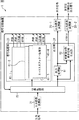
図1は、番組制作用の従来の信号切換装置1の構成例を示すブロック図である。
[Conventional signal switching device]
FIG. 1 is a block diagram showing a configuration example of a conventional
図1に示されるように、従来の信号切換装置1は、入力信号変換部21、切換処理部22、信号処理部23、出力部24、出力信号変換部25−1、及び出力信号変換部25−2から構成されている。
As shown in FIG. 1, the conventional
入力信号変換部21は、外部から入力された映像信号を、信号切換装置1の機器内で取り扱うことが可能な形態の信号(以下、機器内信号と称する)に変換して、切換処理部22に出力する。
The input
切換処理部22は、入力信号変換部21から入力された機器内信号、または信号処理部23から再入力された機器内信号を、選択的に切り換えて、所定の出力先に出力する。出力先としては、図1の例では、信号処理部23、及び出力部24が存在する。すなわち、切換処理部22から出力された機器内信号は、信号処理部23または出力部24に入力される。
The
信号処理部23は、切換処理部22から入力される機器内信号に対して各種の信号処理を施す。信号処理部23により信号処理が施された機器内信号は、信号処理部23から出力されて切換処理部22に再入力される。なお、切換処理部22から信号処理部23に入力された機器内信号が信号処理部23で信号処理を施され、切換処理部22に再入力される一連の処理は、複数回連続して実行される場合もある。
The signal processing unit 23 performs various types of signal processing on the in-device signal input from the
信号処理部23は、このような各種信号処理を実行すべくミックスエフェクト処理部41−1乃至41−4を含むように構成されている。 The signal processing unit 23 is configured to include mix effect processing units 41-1 to 41-4 so as to execute such various signal processing.
なお、図1においては、信号処理部23内には、ミックスエフェクト処理部41−1乃至41−4しか図示されていないが、その他の各種信号処理を行う各種構成要素が存在し得る。例えば、フレームメモリ、モザイク処理等の特殊効果を施す特殊効果処理部、2次元画像を3次元画像に変換する効果処理を施す3次元効果処理部等の構成要素が、信号処理部23内に適宜設けられる。 In FIG. 1, only the mix effect processing units 41-1 to 41-4 are shown in the signal processing unit 23, but various other components for performing various types of signal processing may exist. For example, components such as a special effect processing unit that performs special effects such as frame memory and mosaic processing, and a three-dimensional effect processing unit that performs effect processing for converting a two-dimensional image into a three-dimensional image are appropriately included in the signal processing unit 23. Provided.
なお、以下、ミックスエフェクト処理部41−1乃至41−4を個々に区別する必要がない場合、これらをまとめてミックスエフェクト処理部41と称する。 Hereinafter, when it is not necessary to individually distinguish the mix effect processing units 41-1 to 41-4, they are collectively referred to as a mix effect processing unit 41.
ミックスエフェクト処理部41は、切換処理部22から入力される機器内信号としての2以上の映像をミックスしたり、映像にワイプ切換処理、キー処理等の各種エフェクトを付加してミックスする信号処理(以下、ミックスエフェクト処理と称する)を施す。ミックスエフェクト処理部41がミックスエフェクト処理を実行している最中には、複数の中間生成信号が生成される。そして、ミックスエフェクト処理部41は、ミックスエフェクト処理を全て施した最終形態の映像信号の他、これら複数の中間生成信号も併せて出力する。
The mix effect processing unit 41 mixes two or more images as in-device signals input from the
[ミックスエフェクト処理部41によって出力される各信号]
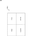
図2は、このようにしてミックスエフェクト処理部41から出力される各映像信号の例を説明する図である。
[Each signal output by the mix effect processing unit 41]
FIG. 2 is a diagram illustrating an example of each video signal output from the mix effect processing unit 41 in this way.
図2の例では、PGM(Program)、PVW(Preview)、CLEAN、及びKPVW(Key Preview)の各映像信号がミックスエフェクト処理部41から出力される。 In the example of FIG. 2, PGM (Program), PVW (Preview), CLEAN, and KPVW (Key Preview) video signals are output from the mix effect processing unit 41.
すなわち、ミックスエフェクト処理部41は、シーンを切り換えながら1以上のオブジェクトを選択的に重畳させていく映像を、最終的に放送される番組の映像として、2つのシーンの映像信号に対してミックスエフェクト処理を施す。 That is, the mix effect processing unit 41 uses a video that selectively superimposes one or more objects while switching scenes as a video of a program that is finally broadcasted, and mix effects on video signals of two scenes. Apply processing.
一定時間かけて、切り換え前後の2つのシーンを画面内で分割合成しながら徐々にシーンを切り換えていく処理が、ワイプ切換処理と称されている。このようなワイプ切換処理が施された後の映像が、映像CLEANと称されている。また、複数のオブジェクトの中から、選択した1以上のオブジェクトを映像に切り抜き合成する処理が、キー(key)処理と称されている。キー処理で選択対象となる全てのオブジェクトが映像CLEANに切り抜き合成された場合に得られる映像が、映像KPVWと称されている。 The process of gradually switching the scene while dividing and synthesizing the two scenes before and after the switching within a screen over a certain time is called a wipe switching process. An image after such a wipe switching process is referred to as an image CLEAN. In addition, a process of cutting out and synthesizing one or more selected objects from a plurality of objects into a video is referred to as a key process. A video obtained when all objects to be selected by key processing are cut out and synthesized into video CLEAN is called video KPVW.
ただし、最終的に放送される番組の映像は、上述したように、全てのオブジェクトではなく、キー処理により選択された1以上のオブジェクト(結果として、キー処理により全オブジェクトが選択される場合もあり得る)が映像CLEANに切り抜き合成された映像である。このような最終的に放送される番組のうち一定期間の映像信号、例えばワイプ切換処理の期間分の映像信号は、ほぼ同時期にミックスエフェクト処理部41により生成される。このようにしてミックスエフェクト処理部41により生成された映像信号に対応する番組の映像のうち、表示対象の映像が映像PGMと称されており、ワイプ切換処理後の次の映像が映像PVWと称されている。 However, as described above, the video of the program to be finally broadcast is not all objects but one or more objects selected by key processing (as a result, all objects may be selected by key processing). Is an image that is cut out and synthesized into the image CLEAN. Of such a program that is finally broadcast, a video signal for a certain period, for example, a video signal for the period of the wipe switching process, is generated by the mix effect processing unit 41 almost at the same time. Of the video of the program corresponding to the video signal generated by the mix effect processing unit 41 in this way, the video to be displayed is referred to as video PGM, and the next video after the wipe switching process is referred to as video PVW. Has been.
図1の例では、4つのミックスエフェクト処理部41−1乃至41−4のそれぞれは、PGM、PVW、CLEAN、及びKPVWの各映像信号、すなわち4種類の映像信号を出力して、切換処理部22に再入力させる。すなわち、これらの4種類の映像信号を1組とすると、4つのミックスエフェクト処理部41−1乃至41−4毎に1組の映像信号がそれぞれ出力されるので、全体として、合計16種類の映像信号が4つのミックスエフェクト処理部41−1乃至41−4から出力されて、切換処理部22に再入力される。
In the example of FIG. 1, each of the four mix effect processing units 41-1 to 41-4 outputs video signals of PGM, PVW, CLEAN, and KPVW, that is, four types of video signals, and a switching processing unit. 22 is input again. That is, assuming that these four types of video signals are one set, one set of video signals is output for each of the four mix effect processing units 41-1 to 41-4, so that a total of 16 types of video signals are obtained. Signals are output from the four mix effect processing units 41-1 to 41-4 and re-input to the
このようにして、切換処理部22に再入力された16種類の映像信号は、出力部24に出力される。この場合、出力部24は、切換処理部22から入力される合計16種類の映像信号に対して各種信号処理を施して、出力信号変換部25−1と25−2に出力する。
In this way, the 16 types of video signals re-input to the
出力部24は、このような各種信号処理を実行すべく、出力処理部61、及び多画面分割表示信号生成部62から構成されている。
The output unit 24 includes an
なお、切換処理部22から出力部24に入力される映像信号は、上述の16種類の映像信号に特に限定されず、当該16種類及び別の種類の映像信号のうち、任意の数の任意の種類の映像信号があり得る。ただし、以下の説明では、説明の便宜上、上述の16種類の映像信号、または、編集後の1種類の映像信号(映像信号PGMに相当)が、出力部24に入力されるものとして説明する。この場合、上述の16種類の映像信号は、多画面分割表示信号の生成に用いられ、編集後の1種類の映像信号は、最終的な番組放送用の映像信号として用いられるものとする。そこで、以下、上述の16種類の映像信号を、多画面分割表示生成用映像信号群と称し、編集後の1種類の映像信号を編集後映像信号と称する。
Note that the video signal input from the switching
出力処理部61は、切換処理部22から入力される編集後映像信号に、出力処理を適宜施した上で、出力信号変換部25−1に出力する。また、出力処理部61は、多画面分割表示生成用映像信号群を、それに出力処理を適宜施した上で、多画面分割表示信号生成部62に出力する。
The
出力信号変換部25−1は、出力処理部61から出力された編集後映像信号を、機器内信号の形態から、図示せぬ表示装置等で取り扱える形態に変換して、表示装置等に出力する。これにより、表示装置等には、上述したように、編集後映像信号に対応する映像が表示される。
The output signal conversion unit 25-1 converts the edited video signal output from the
多画面分割表示信号生成部62は、切換処理部22または出力処理部61から入力される多画面分割表示生成用映像信号群の中から、多画面分割表示における分割表示数、すなわち子画面数の映像信号を選択的に切り換える。この場合の分割表示数は、任意の数が設定可能とされている。そして、多画面分割表示信号生成部62は、選択した映像信号の各々に対応する映像を各子画面に分割表示できるように、各映像信号を合成することによって、多画面分割表示信号を生成して出力信号変換部25−2に出力する。
The multi-screen split display
[多画面分割表示信号の一例]
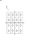
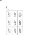
図3は、多画面分割表示信号生成部62から出力される多画面分割表示信号の一例を示す図である。
[Example of multi-screen split display signal]
FIG. 3 is a diagram illustrating an example of a multi-screen split display signal output from the multi-screen split display
図3の例では、多画面分割表示信号生成部62は、ミックスエフェクト処理部41−1乃至41−4から出力された多画面分割表示生成用映像信号群、すなわち16種類の映像信号の一部を選択しているのではなく、16種類の映像信号の全てを選択している。そして、多画面分割表示信号生成部62は、これらの16種類の映像信号の全てを合成することによって、多画面分割表示信号s16mixを生成する。多画面分割表示信号s16mix(より正確には、出力信号変換部25−2によって出力形態が変換された映像信号)とは、図3に示されるように、16種類の映像の各々が各子画面に分割表示される多画面分割表示を実現する映像信号をいう。
In the example of FIG. 3, the multi-screen split display
図3の各子画面内の文字は、当該子画面に表示される映像の種類を表わしている。各子画面内に図示されている「#K」は、ミックスエフェクト処理部41−Kの符号の最後の「K」に対応している。すなわち、「#K」が図示されている子画面内には、ミックスエフェクト処理部41−Kから出力された4種類の映像信号に対応する映像のうち、当該子画面内に図示された種類の映像が表示される。 The characters in each child screen in FIG. 3 represent the type of video displayed on the child screen. “#K” illustrated in each sub-screen corresponds to the last “K” of the code of the mix effect processing unit 41-K. That is, in the sub-screen in which “#K” is illustrated, among the videos corresponding to the four types of video signals output from the mix effect processing unit 41-K, the type illustrated in the sub-screen. An image is displayed.
具体的には、「#1」が図示された左上の4つの子画面の各々は、ミックスエフェクト処理部41−1から出力された4種類の映像信号の各々に対応する、PGM、PVW、CLEAN、及びKPVWの各々の映像が表示される。同様に、「#2」が図示された右上の4つの子画面の各々は、ミックスエフェクト処理部41−2から出力された4種類の映像信号の各々に対応する、PGM、PVW、CLEAN、及びKPVWの各々の映像が表示される。「#3」が図示された左下の4つの子画面の各々は、ミックスエフェクト処理部41−3から出力された4種類の映像信号の各々に対応する、PGM、PVW、CLEAN、及びKPVWの各々の映像が表示される。「#4」が図示された右下の4つの子画面の各々は、ミックスエフェクト処理部41−4から出力された4種類の映像信号の各々に対応する、PGM、PVW、CLEAN、及びKPVWの各々の映像が表示される。 Specifically, each of the upper left four sub-screens with “# 1” illustrated corresponds to each of the four types of video signals output from the mix effect processing unit 41-1, PGM, PVW, CLEAN , And KPVW images are displayed. Similarly, each of the four sub-screens at the upper right where “# 2” is illustrated is PGM, PVW, CLEAN, and each corresponding to each of the four types of video signals output from the mix effect processing unit 41-2. Each video of KPVW is displayed. Each of the four sub-screens at the lower left where “# 3” is illustrated is each of PGM, PVW, CLEAN, and KPVW corresponding to each of the four types of video signals output from the mix effect processing unit 41-3. Is displayed. Each of the four sub-screens at the lower right where “# 4” is illustrated is PGM, PVW, CLEAN, and KPVW corresponding to each of the four types of video signals output from the mix effect processing unit 41-4. Each video is displayed.
出力信号変換部25−2は、多画面分割表示信号生成部62から出力された多画面分割表示信号s16mixを、機器内信号の形態から、図示せぬ表示装置等で取り扱える形態に変換して、表示装置等に出力する。これにより、表示装置等には、上述したように、図3に示す16分割画面が表示される。
The output signal conversion unit 25-2 converts the multi-screen split display signal s16mix output from the multi-screen split display
以上説明したように、図1の信号切換装置1は、画面分割表示数(すなわち子画面の総数)が「16」の多画面分割表示を実現する。このために、信号切換装置1では、16個の各子画面の各々に対応する16種類の映像信号が、多画面分割表示生成用映像信号群として信号処理部23のミックスエフェクト処理部41−1乃至41−4から出力されて、切換処理部22に再入力される。したがって、ミックスエフェクト処理部41−1乃至41−4を有する信号処理部23においては、16種類の映像信号の各々を伝達する16本の信号線が必要になる。
As described above, the
さらに、上述の例では、多画面分割表示信号生成部62に入力される多画面分割表示生成用映像信号群の信号数と、多画面分割表示信号生成部62内で選択される信号数とは「16」と一致していたが、常に一致しているとは限らない。すなわち、一般的には、多画面分割表示信号生成部62に入力される多画面分割表示生成用映像信号群の信号数の方が多く、多画面分割表示生成用映像信号群内の一部の映像信号のみが選択的に切り換えられて、多画面分割表示信号の生成に用いられる。
Further, in the above-described example, the number of signals of the video signal group for multi-screen split display generation input to the multi-screen split display
より一般的にいえば、画面分割表示数(すなわち子画面の総数)がM個の多画面分割表示を実現する場合には、信号切換装置1では、ミックスエフェクト処理部41−1乃至41−4を有する信号処理部23における信号線の数がM本以上必要になる。
More generally speaking, in the case of realizing multi-screen split display with the number of screen split displays (that is, the total number of sub-screens), in the
さらにまた、図1には図示しなったが、その他の信号処理の機能が信号処理部23に必要な場合、当該機能を実現するための構成要素が必要になり、その分だけ、信号線の数が増加する。 Furthermore, as shown in FIG. 1, when other signal processing functions are required for the signal processing unit 23, components for realizing the functions are required, and the signal line is increased accordingly. The number increases.
したがって、上述した要望、すなわち、画面分割表示数(すなわち子画面の総数)や、選択的に切り換えられる元の映像信号の総数を増やして多画面分割表示をしたいという要望に応えるためには、従来の信号処理装置では、内部の信号線の数が増大することになる。また、そのような数多くの信号線を入出力する回路、例えば、切換処理部22、信号処理部23、多画面分割表示信号生成部62等を実現化する回路の規模も増大することになる。
Therefore, in order to meet the above-mentioned demand, that is, the demand for the multi-screen split display by increasing the total number of screen split displays (that is, the total number of sub-screens) and the total number of original video signals that can be selectively switched, In this signal processing apparatus, the number of internal signal lines increases. In addition, the scale of a circuit that realizes such a circuit that inputs and outputs many signal lines, for example, the switching
ミックスエフェクト処理部41の搭載数は、信号切換装置1全体の規模を表わす場合があり、ミックスエフェクト処理部41の搭載数がK個(Kは1以上の整数値)のときには、信号切換装置1の規模はK M/Eと表現される。図1の例では、4つのミックスエフェクト処理部41−1乃至41−4が図示されているので、信号切換装置1の規模は4M/Eである。
The number of installed mix effect processing units 41 may represent the overall scale of the
多画面分割表示信号生成部62の機能と低コスト化とはトレードオフの関係であることから、従来は、3M/E以上の大規模な信号切換装置1には、多画面分割表示信号生成部62は内蔵されていない。
Since the function of the multi-screen split display
本発明は、このような状況に鑑みてなされたものであり、画面分割表示数、及び子画面に表示可能とする信号切換装置内部信号の数が増えても回路規模の増大を抑制して多画面分割表示ができるようにしたものである。 The present invention has been made in view of such a situation, and suppresses an increase in circuit scale even when the number of divided screen displays and the number of signal switching device internal signals that can be displayed on a sub screen increase. The screen can be divided and displayed.
本発明の一側面の信号処理装置は、複数の映像信号を入力する入力手段と、前記入力手段に入力された前記複数の映像信号に対して、信号処理を施す信号処理手段と、前記信号処理手段により前記信号処理が施された前記複数の映像信号、及び、前記信号処理手段が前記信号処理を施している途中に生成される1以上の映像信号である中間生成信号の中から、P種類(Pは2以上の整数値)の映像信号を選択して合成することによって、サブ多画面分割表示信号を生成する、1以上のサブ多画面分割表示信号生成手段と、1以上の前記サブ多画面分割表示信号生成手段の各々により生成された1以上のサブ多画面分割表示信号のうち、Q種類(Qは1以上の整数値)のサブ多画面分割表示信号を選択して合成することによって、多画面分割表示信号を生成する多画面分割表示信号生成手段とを備える。 The signal processing apparatus according to one aspect of the present invention includes an input unit that inputs a plurality of video signals, a signal processing unit that performs signal processing on the plurality of video signals input to the input unit, and the signal processing P types of the plurality of video signals subjected to the signal processing by the means and one or more intermediate generated signals which are one or more video signals generated during the signal processing by the signal processing means One or more sub-multi-screen divided display signal generating means for generating a sub-multi-screen divided display signal by selecting and synthesizing video signals (P is an integer value of 2 or more) and one or more of the sub-multi-screen signals. By selecting and synthesizing Q types (Q is an integer value of 1 or more) of sub-multi-screen split display signals generated from each of the one or more sub-multi-screen split display signals generated by each of the split screen display signal generating means. Multi-screen contingency table And a multi-split screen display signal generating means for generating a signal.
前記サブ多画面分割表示信号生成手段は、前記信号処理手段の構成要素とすることができる。 The sub multi-screen divided display signal generating means can be a component of the signal processing means.
前記信号処理手段は、前記信号処理として、前記入力手段に入力された複数の前記映像信号に対してエフェクトを付加してミックスするミックスエフェクト処理を施す、1以上のミックスエフェクト処理手段を備え、前記1以上のミックスエフェクト処理手段のそれぞれの構成要素として、前記サブ多画面分割表示信号生成手段が設けられており、前記サブ多画面分割表示信号生成手段は、前記ミックスエフェクト処理手段により前記ミックスエフェクト処理が施された前記複数の映像信号、及び、前記ミックスエフェクト処理手段が前記ミックスエフェクト処理を施している途中に生成される1以上の映像信号である中間生成信号の中から、P種類の映像信号を選択して合成することによって、前記サブ多画面分割表示信号を生成することができる。 The signal processing means includes one or more mix effect processing means for performing a mix effect process for adding and mixing effects to the plurality of video signals input to the input means as the signal processing, The sub multi-screen split display signal generating means is provided as a component of each of the one or more mix effect processing means, and the sub multi-screen split display signal generating means is configured to perform the mix effect processing by the mix effect processing means. P types of video signals from among the plurality of video signals subjected to, and intermediate generation signals that are one or more video signals generated while the mix effect processing means is performing the mix effect processing Generating the sub multi-screen split display signal by selecting and combining It can be.
前記信号処理手段は、前記信号処理として、前記入力手段に入力された複数の前記映像信号、並びに、前記信号処理手段から出力される前記信号処理が施された前記複数の映像信号、前記中間生成信号、及び前記サブ多画面分割表示信号のうち、少なくとも一部の映像信号を記憶するフレームメモリを備え、前記フレームメモリの構成要素として、前記サブ多画面分割表示信号生成手段が設けられており、前記サブ多画面分割表示信号生成手段は、前記フレームメモリにより記憶された映像信号の中から、P種類の映像信号を選択して合成することによって、前記サブ多画面分割表示信号を生成することができる。 The signal processing means includes, as the signal processing, the plurality of video signals input to the input means, the plurality of video signals subjected to the signal processing output from the signal processing means, and the intermediate generation A signal and a frame memory for storing at least a part of the sub-multi-screen split display signal, and the sub-multi-screen split display signal generating means is provided as a component of the frame memory, The sub multi-screen split display signal generating means may generate the sub multi-screen split display signal by selecting and synthesizing P types of video signals from the video signals stored in the frame memory. it can.
前記信号処理手段は、前記信号処理として、前記入力手段に入力された複数の前記映像信号、並びに、前記信号処理手段から出力される前記信号処理が施された前記複数の映像信号、前記中間生成信号、及び前記サブ多画面分割表示信号のうち、少なくとも一部の映像信号に対して特殊効果処理を施す特殊効果処理手段を備え、前記特殊効果処理手段の構成要素として、前記サブ多画面分割表示信号生成手段が設けられており、前記サブ多画面分割表示信号生成手段は、前記特殊効果処理手段により前記特殊効果処理が施された前記映像信号、及び、前記特殊効果処理手段が前記特殊効果処理を施している途中に生成される1以上の映像信号である中間生成信号の中から、P種類の映像信号を選択して合成することによって、前記サブ多画面分割表示信号を生成することができる。 The signal processing means includes, as the signal processing, the plurality of video signals input to the input means, the plurality of video signals subjected to the signal processing output from the signal processing means, and the intermediate generation A special effect processing means for performing special effect processing on at least a part of the signal and the sub multi-screen split display signal, and the sub multi-screen split display as a component of the special effect processing means Signal generating means is provided, the sub-multi-screen divided display signal generating means is the video signal that has been subjected to the special effect processing by the special effect processing means, and the special effect processing means is the special effect processing. By selecting and synthesizing P types of video signals from intermediate generated signals that are one or more video signals generated in the middle of the sub-multi-screen, It is possible to generate a split display signal.
前記信号処理手段は、前記信号処理として、前記入力手段に入力された複数の前記映像信号、並びに、前記信号処理手段から出力される前記信号処理が施された前記複数の映像信号、前記中間生成信号、及び前記サブ多画面分割表示信号のうち、少なくとも一部の映像信号を、3次元画像表示のための映像信号に変換する3次元効果処理を実行する3次元効果処理手段を備え、前記3次元効果処理手段の構成要素として、前記サブ多画面分割表示信号生成手段が設けられており、前記サブ多画面分割表示信号生成手段は、前記3次元効果処理手段により前記3次元効果処理が施された前記映像信号、及び、前記3次元効果処理手段が前記3次元効果処理を施している途中に生成される1以上の映像信号である中間生成信号の中から、P種類の映像信号を選択して合成することによって、前記サブ多画面分割表示信号を生成することができる。 The signal processing means includes, as the signal processing, the plurality of video signals input to the input means, the plurality of video signals subjected to the signal processing output from the signal processing means, and the intermediate generation 3D effect processing means for executing 3D effect processing for converting at least a part of the signal and the sub-multi-screen divided display signal into a video signal for 3D image display, The sub multi-screen split display signal generating means is provided as a component of the dimension effect processing means, and the sub multi-screen split display signal generating means is subjected to the three-dimensional effect processing by the three-dimensional effect processing means. From the video signal and one or more intermediate generation signals that are one or more video signals generated while the three-dimensional effect processing means is performing the three-dimensional effect processing, By combining select the image signal, it is possible to generate the sub-multiscreen split display signal.
本発明の一側面の信号処理方法及びプログラムは、上述した本発明の一側面の信号処理装置に対応する方法及びプログラムである。 A signal processing method and program according to one aspect of the present invention are a method and program corresponding to the signal processing apparatus according to one aspect of the present invention described above.
本発明の一側面の信号処理装置及び方法並びにプログラムにおいては、複数の映像信号が入力され、入力された前記複数の映像信号に対して、信号処理が施される。前記信号処理が施された前記複数の映像信号、及び、前記信号処理が施されている途中に生成される1以上の映像信号である中間信号の中から、P種類(Pは2以上の整数値)の映像信号が選択されて合成されることによって、サブ多画面分割表示信号が生成される。生成された1以上のサブ多画面分割表示信号のうち、Q種類(Qは1以上の整数値)のサブ多画面分割表示信号が選択されて合成されることによって、多画面分割表示信号が生成される。 In the signal processing apparatus, method, and program according to one aspect of the present invention, a plurality of video signals are input, and signal processing is performed on the input video signals. Among the plurality of video signals that have been subjected to the signal processing and one or more intermediate signals that are one or more video signals that are generated while the signal processing is being performed, P types (P is an integer of two or more). Sub-multiscreen split display signals are generated by selecting and synthesizing (numerical) video signals. Of the generated one or more sub-multi-screen split display signals, Q types (Q is an integer value of 1 or more) of sub-multi-screen split display signals are selected and combined to generate a multi-screen split display signal. Is done.
以上のごとく、本発明によれば、画面分割表示数、及び子画面に表示可能とする信号切換装置内部信号の数が増えても回路規模の増大を抑制して多画面分割表示ができる。 As described above, according to the present invention, even if the number of screen division displays and the number of signal switching device internal signals that can be displayed on the sub-screen increase, it is possible to perform multi-screen division display while suppressing an increase in circuit scale.
以下、3つの実施形態(以下、それぞれ第1実施形態乃至第3実施形態と称する)について、次の順序で説明する。 Hereinafter, three embodiments (hereinafter referred to as first to third embodiments, respectively) will be described in the following order.
1.第1実施形態(PGM、PVW、CLEAN、及びKPVWの各映像信号からなる多画面分割表示信号の例)
2.第2実施形態(キー調整用信号からなる多画面分割表示信号の例)
3.第3実施形態(3次元画像の多画面分割表示信号の例)
1. First Embodiment (Example of a multi-screen split display signal composed of PGM, PVW, CLEAN, and KPVW video signals)
2. Second Embodiment (Example of a multi-screen split display signal composed of key adjustment signals)
3. Third Embodiment (Example of multi-screen divided display signal of 3D image)
<1.第1実施形態>
[本実施形態の信号切換装置の構成例]
図4は、本発明が適用される信号処理装置の一実施形態としての番組制作用の信号切換装置101の構成例を示すブロック図である。
<1. First Embodiment>
[Configuration example of signal switching device of this embodiment]
FIG. 4 is a block diagram illustrating a configuration example of a
図4に示されるように、本実施形態の信号切換装置101は、入力信号変換部121、切換処理部122、信号処理部123、出力部124、出力信号変換部125−1及び出力信号変換部125−2、操作部126、並びに制御部127から構成されている。
As shown in FIG. 4, the
入力信号変換部121は、外部から入力された映像信号を、信号切換装置101の機器内で取り扱うことが可能な形態の機器内信号に変換して、切換処理部122に出力する。例えば、本実施形態では、入力信号変換部121に入力される映像信号としては、SDI(serial digital interface)信号が採用されている。また、例えば、本実施形態では、機器内信号として、差動信号が採用されている。
The input
切換処理部122は、入力信号変換部121から入力された機器内信号、または信号処理部123から再入力された機器内信号を、選択的に切り換えて、所定の出力先に出力する。出力先としては、図4の例では、信号処理部123、及び出力部124が存在する。すなわち、切換処理部122から出力された機器内信号(以下、適宜映像信号とも称する)は、信号処理部123または出力部124に入力される。
The switching
信号処理部123は、切換処理部122から入力される機器内信号に対して各種の信号処理を施す。信号処理部123が信号処理を施している途中で、各種映像信号が生成される。すなわち、本実施形態では、信号処理部123による信号処理中に中間生成信号が生成される。信号処理部123により信号処理が施された機器内信号は、信号処理部123から出力されて切換処理部122に再入力される。なお、切換処理部122から信号処理部123に入力された機器内信号が信号処理部123で信号処理を施され、切換処理部122に再入力される一連の処理は、複数回連続して実行される場合もある。
The signal processing unit 123 performs various types of signal processing on the in-device signal input from the switching
信号処理部123には、ミックスエフェクト処理部141−1乃至141−4が設けられている。ミックスエフェクト処理部141−1乃至141−4は、切換処理部122から入力される機器内信号に対してワイプ切換処理、キー処理等の各種エフェクトを付加しミックスするミックスエフェクト処理を施す。ミックスエフェクト処理部141−1乃至141−4がミックスエフェクト処理を施している途中には、中間生成信号が生成される。なお、以下、ミックスエフェクト処理部141−1乃至141−4を個々に区別する必要がない場合、これらをまとめてミックスエフェクト処理部141と称する。
The signal processing unit 123 is provided with mix effect processing units 141-1 to 141-4. The mix effect processing units 141-1 to 141-4 perform mix effect processing that adds various effects such as wipe switching processing and key processing to the in-device signal input from the switching
ミックスエフェクト処理部141は、このようなミックスエフェクト処理を実行すべく、合成処理部161、ワイプ切換信号生成部162、キー調整部163、及びサブ多画面分割表示信号生成部164から構成されている。
The mix effect processing unit 141 includes a
合成処理部161は、切換処理部122から入力される機器内信号に対して、ミックスエフェクト処理を施す。また、合成処理部161は、ミックスエフェクト処理を実行している最中に、複数の中間生成信号を生成する。
The
例えば本実施形態では、切換処理部122から1つのミックスエフェクト処理部141に対しては、第1のシーンの映像(以下、映像BGAと称する)の映像信号(以下、映像信号BGAと称する)と、第2のシーンの映像(以下、映像BGBと称する)の映像信号(以下、映像信号BGBと称する)とが入力されるとする。
For example, in the present embodiment, from the switching
この場合、合成処理部161は、映像信号BGAと映像信号BGBに基づいて、一定時間をかけて、切り換え前後の2つのシーン(映像BGA及び映像BGB)を画面内で分割合成しながら徐々にシーンを切り換えていく処理、すなわちワイプ切換処理を実行する。これにより、ワイプ切換処理が施された後の映像である映像CLEANの映像信号(以下、映像信号CLEANと称する)が生成される。
In this case, the
このような合成処理部161によって実行されるワイプ切換処理の処理方法は、ワイプ切換信号によって特定される。換言すると、ワイプ切換信号とは、例えば、2つのシーンのどちらからどちらに切り換えるのかといった切換方法、2つのシーンの分割合成の比率等ワイプ切換処理の処理方法を特定する信号をいう。
The processing method of the wipe switching process executed by the
ワイプ切換信号生成部162は、このようなワイプ切換信号を生成し、合成処理部161に出力する。
The wipe switching
合成処理部161はまた、複数のオブジェクトの中から、選択した1以上のオブジェクトを映像CLEANに切り抜き合成する処理、すなわちキー処理を実行する。
The
この場合、1つのオブジェクトを示す映像信号を、以下、キー調整用信号と称する。すなわち、合成処理部161は、複数のオブジェクトの中から、選択した1以上のオブジェクトのキー調整用信号を、映像信号CLEANに合成することによって、キー処理を実現する。
In this case, a video signal indicating one object is hereinafter referred to as a key adjustment signal. That is, the
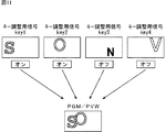
キー調整部163は、このようなキー調整用信号を、切り抜き合成の対象となるオブジェクト毎に生成する。例えば、本実施形態では、8つのオブジェクトが切り抜き合成の対象とされており、8つのオブジェクトの各々に対応するキー調整用信号key1乃至key8が生成される。
The
この場合、キー調整用信号key1乃至key8の各々は、オン状態またはオフ状態が設定される。オン状態とは、キー処理において利用されることを意味する一方、オフ状態とは、キー処理において利用が禁止されることを意味する。すなわち、キー調整用信号key1乃至key8のうち、オン状態のキー調整用信号に対応するオブジェクトが、キー処理で切り抜き合成される一方、オフ状態のキー調整用信号に対応するオブジェクトは、キー処理で切り抜き合成されない。 In this case, each of the key adjustment signals key1 to key8 is set to an on state or an off state. The on state means that the key processing is used, while the off state means that the key processing is prohibited. That is, among the key adjustment signals key1 to key8, the object corresponding to the key adjustment signal in the on state is cut out and synthesized by the key processing, while the object corresponding to the key adjustment signal in the off state is the key processing. Cutout is not combined.
このようにして、キー処理において、キー調整用信号key1乃至key8のうち、オン状態のキー調整用信号が映像信号CLEANに合成されることによって、最終的に放送される番組の映像信号(機器内信号)が得られる。ここで、本実施形態では、最終的に放送される番組のうち、ワイプ切換処理の期間分の映像信号が、ほぼ同時期に合成処理部161により生成されるとする。
In this way, in the key processing, the key adjustment signal in the on state among the key adjustment signals key1 to key8 is combined with the video signal CLEAN, so that the video signal of the program to be finally broadcast (inside the device) Signal). Here, in the present embodiment, it is assumed that the video signal for the period of the wipe switching process is generated by the
この場合、合成処理部161は、所定のタイミングでは、最終的に放送される番組の映像信号のうち、表示対象の映像PGM(Program)の映像信号(以下、PGM映像信号と称する)と、ワイプ切換処理後の次の映像PVW(Preview)の映像信号(以下、PVW映像信号と称する)とを生成したことになる。
In this case, the
そして、映像信号PGMと映像信号PVWが生成された所定のタイミングでは、映像信号CLEAN、及び映像KPVW(Key Preview)の映像信号(以下、映像信号KPVWと称する)が得られている。 At a predetermined timing when the video signal PGM and the video signal PVW are generated, the video signal CLEAN and the video signal of the video KPVW (Key Preview) (hereinafter referred to as the video signal KPVW) are obtained.
ここで得られている映像信号KPVWとは、キー調整用信号key1乃至key8の全てがオン状態にされたとして、キー調整用信号key1乃至key8の全てが映像信号CLEANに合成された結果得られる信号と等価の映像信号である。具体的には、キー調整部163は、キー調整用信号key1乃至key8を合成することによって、合成キー調整用信号keyallを生成する。合成処理部161は、合成キー調整用信号keyallを映像信号CLEANに切り抜き合成することによって、映像信号KPVWを生成する。
The video signal KPVW obtained here is a signal obtained as a result of combining all of the key adjustment signals key1 to key8 with the video signal CLEAN, assuming that all of the key adjustment signals key1 to key8 are turned on. Is an equivalent video signal. Specifically, the
さらに、映像信号PGMと映像信号PVWが生成された所定のタイミングでは、キー調整用信号key1乃至key8や、ワイプ切換信号も得られている。 Furthermore, key adjustment signals key1 to key8 and wipe switching signals are also obtained at predetermined timings when the video signal PGM and the video signal PVW are generated.
そこで、合成処理部161は、ワイプ切換信号、キー調整用信号key1乃至key8及び合成キー調整用信号keyall、並びにPGM、PVW、CLEAN、及びKPVWの各映像信号を、サブ多画面分割表示信号生成部164に出力する。なお、これらの信号のうちの幾つかの信号は、必要に応じて、切換処理部122にも再入力される。
Therefore, the
サブ多画面分割表示信号生成部164は、合成処理部161から入力された複数の信号の中から、任意の数の任意の種類の映像信号を選択的に切り換えて合成することによって、多画面分割表示信号を生成する。なお、合成処理部161から入力される複数の信号のうち、ワイプ切換信号、キー調整用信号key1乃至key8、映像信号CLEAN等は中間生成信号である。
The sub multi-screen division display
なお、サブ多画面分割表示信号生成部164により生成される多画面分割表示信号を、後述するメイン多画面分割表示信号生成部202により生成される多画面分割表示信号と明確に区別すべく、以下、サブ多画面分割表示信号と称する。
In order to clearly distinguish the multi-screen split display signal generated by the sub multi-screen split display
本実施形態では、サブ多画面分割表示信号生成部164は、合成処理部161により生成されたPGM、PVW、CLEAN、及びKPVWの各映像信号を選択して合成することによって、サブ多画面分割表示信号(以下、特に符号s4mixを付す)を生成するものとする。
In the present embodiment, the sub multi-screen split display
[サブ多画面分割表示信号s4mix]
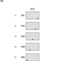
図5は、このようにして、サブ多画面分割表示信号生成部164によって生成されるサブ多画面分割表示信号s4mixを示す図である。
[Sub multi-screen split display signal s4mix]
FIG. 5 is a diagram showing the sub multi-screen split display signal s4mix generated by the sub multi-screen split display
サブ多画面分割表示信号s4mixは、PGM、PVW、CLEAN、及びKPVWの各映像信号で構成される。すなわち、サブ多画面分割表示信号s4mix(より正確には、出力形態が変換された映像信号)が仮に図示せぬ表示装置等に入力されたならば、図5に示されるように、4種類の映像の各々が各子画面に分割表示される。 The sub multi-screen split display signal s4mix is composed of PGM, PVW, CLEAN, and KPVW video signals. In other words, if the sub-multi-screen divided display signal s4mix (more precisely, the video signal whose output form has been converted) is input to a display device (not shown) or the like, as shown in FIG. Each video is divided and displayed on each sub-screen.
ミックスエフェクト処理部141−1乃至141−4のそれぞれのサブ多画面分割表示信号生成部164は、相互に独立してサブ多画面分割表示信号s4mixを生成する。すなわち、4つのミックスエフェクト処理部141−1乃至141−4のそれぞれのサブ多画面分割表示信号生成部164毎に、1種類のサブ多画面分割表示信号s4mixがそれぞれ出力される。したがって、全体として、合計4種類のサブ多画面分割表示信号s4mixが4つのミックスエフェクト処理部141−1乃至141−4から出力されて、切換処理部122に再入力される。
The sub multi-screen split display
信号処理部123には、切換処理部122から入力される機器内信号に対して各種の信号処理を施す構成要素として、このようなミックスエフェクト処理部141−1乃至141−4の他、さらに、フレームメモリ142、特殊効果処理部143、及び3次元効果処理部144も設けられている。
In addition to the mix effect processing units 141-1 to 141-4, the signal processing unit 123 is a component that performs various types of signal processing on the in-device signal input from the switching
フレームメモリ142は、切換処理部122から入力される機器内信号、または信号処理部123に含まれる他の構成要素による信号処理によって生成された機器内信号(すなわち、中間生成信号、サブ多画面分割表示信号を含む)をフレーム単位で記憶する。
The
フレームメモリ142は、サブ多画面分割表示信号生成部171を含むように構成されている。サブ多画面分割表示信号生成部171は、記憶された複数フレーム分の機器内信号の中から、任意の数の任意の種類の機器内信号を選択的に切り換えて合成し、サブ多画面分割表示信号を生成して切換処理部122に再入力する。サブ多画面分割表示信号生成部171により生成されたサブ多画面分割表示信号が仮に図示せぬ表示装置等に入力されたならば、例えば、複数種類の映像の各々が各子画面に分割表示される。
The
特殊効果処理部143は、切換処理部122から入力される複数の機器内信号、または信号処理部123に含まれる他の構成要素による信号処理によって生成された機器内信号(すなわち、中間生成信号、サブ多画面分割表示信号を含む)の少なくとも一部に対して、フィルター、拡大縮小、モザイク処理等の特殊効果処理を順次施す。特殊効果処理部143が特殊効果処理を実行している最中には、複数の中間生成信号が生成される。例えば、フィルター処理後であって拡大縮小処理及びモザイク処理前の信号、フィルター処理及び拡大縮小処理後であってモザイク処理前の信号等が中間生成信号となる。
The special
特殊効果処理部143は、サブ多画面分割表示信号生成部181を含むように構成されている。サブ多画面分割表示信号生成部181は、適宜特殊効果処理が施された複数の機器内信号、及び特殊効果処理を施している途中に生成される1以上の中間生成信号の中から、任意の数の任意の種類の機器内信号を選択的に切り換えて合成し、サブ多画面分割表示信号を生成して切換処理部122に再入力する。サブ多画面分割表示信号生成部181により生成されたサブ多画面分割表示信号が仮に図示せぬ表示装置等に入力されたならば、例えば、フィルター処理だけが施された映像、さらに拡大縮小処理が施された映像、さらにモザイク処理が部分的に施された映像等、複数種類の映像の各々が各子画面に分割表示される。
The special
3次元効果処理部144は、切換処理部122から入力される複数の機器内信号、または信号処理部123に含まれる他の構成要素によって生成された機器内信号(すなわち、中間生成信号、サブ多画面分割表示信号を含む)の各々から、3次元画像表示のための左眼用の機器内信号、及び右眼用の機器内信号を生成したり、加工したりする。3次元効果処理部144が3次元画像表示のための機器内信号を生成する処理をしている最中には、複数の中間生成信号が生成される。例えば、3次元画像表示をした場合に人の目に違和感のないように、表示されるオブジェクトの凹凸の度合いが様々に設定された左眼用の機器内信号、及び右眼用の機器内信号が中間生成信号として生成される。
The three-dimensional effect processing unit 144 includes a plurality of in-device signals input from the switching
3次元効果処理部144は、サブ多画面分割表示信号生成部191を含むように構成されている。サブ多画面分割表示信号生成部191は、複数の左眼用の機器内信号、及び3次元画像表示のための機器内信号を生成する処理を施している途中に生成される1以上の中間生成信号の中から、任意の数の任意の種類の左眼用の機器内信号、及び複数の中間生成信号を選択的に切り換えて合成し、左眼用のサブ多画面分割表示信号を生成する。サブ多画面分割表示信号生成部191は、複数の右眼用の機器内信号、及び3次元画像表示のための機器内信号を生成する処理を施している途中に生成される1以上の中間生成信号の中から、任意の数の任意の種類の右眼用の機器内信号を選択的に切り換えて合成し、右眼用のサブ多画面分割表示信号を生成する。このようにして生成された左眼用と右眼用の各々のサブ多画面分割表示信号は、切換処理部122に再入力される。サブ多画面分割表示信号生成部191により生成されたサブ多画面分割表示信号が仮に図示せぬ表示装置等に入力されたならば、例えば、様々な凹凸の度合いでオブジェクトが表示された映像の各々が各子画面に分割表示される。
The three-dimensional effect processing unit 144 is configured to include a sub multi-screen divided display signal generation unit 191. The sub multi-screen split display signal generation unit 191 generates one or more intermediate generations generated during the process of generating a plurality of in-device signals for the left eye and an in-device signal for displaying a three-dimensional image. From the signals, an arbitrary number of arbitrary types of in-device signals for the left eye and a plurality of intermediate generation signals are selectively switched and synthesized to generate a sub-multi-screen split display signal for the left eye. The sub multi-screen split display signal generation unit 191 generates one or more intermediate generations generated during the process of generating a plurality of in-device signals for the right eye and an in-device signal for displaying a three-dimensional image. From the signals, an arbitrary number of arbitrary types of in-device signals for the right eye are selectively switched and synthesized to generate a sub-multi-screen divided display signal for the right eye. The left-eye and right-eye sub-multi-screen divided display signals generated in this way are re-input to the
なお、本実施形態では、サブ多画面分割表示信号生成部164,171,181,191の各々は、ミックスエフェクト処理部141−1乃至141−4、フレームメモリ142、特殊効果処理部143、及び3次元効果処理部144の各々の構成要素として設けられている。ただし、サブ多画面分割表示信号生成部164,171,181,191の各々は、入力された複数の映像信号、及び中間生成信号の中から、任意の数の任意の種類の複数の信号を選択的に切り換えて合成し、サブ多画面分割表示信号を生成することができる機能を有していれば足りる。すなわち、サブ多画面分割表示信号生成部164,171,181,191の各々の配置位置は、図4の例に特に限定されず、任意の位置、例えば信号処理部123の外部でもよい。
In the present embodiment, each of the sub multi-screen split display
信号処理部123には、上述した構成要素、すなわち、ミックスエフェクト処理部141、フレームメモリ142、特殊効果処理部143、及び3次元効果処理部144以外に、その他の各種信号処理を行う各種構成要素が適宜設けられる。
In the signal processing unit 123, in addition to the above-described constituent elements, that is, the mixed effect processing part 141, the
このようにして、信号処理部123から切換処理部122に各種各様の映像信号が入力される。切換処理部122に再入力された映像信号は、出力部124に適宜出力される。ここで、以下の説明では、説明の便宜上、図1の従来の信号切換装置1との比較を容易にすべく、切換処理部122から出力される信号は、多画面分割表示生成用映像信号群と、編集後映像信号とであるとする。
In this way, various types of video signals are input from the signal processing unit 123 to the
ただし、図1の従来の信号切換装置1においては、PGM、PVW、CLEAN、及びKPVWの何れかの単体に対応する映像信号が、16種類集まった集合体が、多画面分割表示生成用映像信号群として採用されていた。これに対して、本実施形態の信号切換装置101においては、PGM、PVW、CLEAN、及びKPVWの各々が合成された4分割画像に対応するサブ多画面分割表示信号s4mix1乃至s4mix4の集合体が、多画面分割表示生成用映像信号群として採用されている。
However, in the conventional
出力部124は、切換処理部122から入力される多画面分割表示生成用映像信号群、または編集後映像信号に対して各種信号処理を施して、出力信号変換部125−1、または出力信号変換部125−2に出力する。
The output unit 124 performs various signal processing on the multi-screen divided display generation video signal group or the edited video signal input from the switching
出力部124は、出力処理部201、及びメイン多画面分割表示信号生成部202から構成されている。
The output unit 124 includes an
出力処理部201は、切換処理部122から入力される編集後映像信号に対して、必要に応じてセーフタイトル、スーパーインポーズ等の出力処理を施し、出力信号変換部125−1に出力する。また、出力処理部201は、切換処理部122から入力される多画面分割表示生成用映像信号群、すなわち、4種類のサブ多画面分割表示信号s4mix1乃至s4mix4に対して、必要に応じてセーフタイトル、スーパーインポーズ等の出力処理を施し、メイン多画面分割表示信号生成部202に出力する。
The
出力信号変換部125−1は、出力処理部201から入力される編集後映像信号を、機器内信号の形態から表示装置等に適した形態に変換し、具体的には本実施形態では差動信号をSDI信号に変換し、出力信号として図示せぬ表示装置等に出力する。
The output signal conversion unit 125-1 converts the edited video signal input from the
メイン多画面分割表示信号生成部202は、切換処理部122または出力処理部201から入力される複数の映像信号の中から、多画面分割表示における分割表示数、すなわち子画面の総数の映像信号を選択的に切り換える。
The main multi-screen split display
ただし、本実施形態では、多画面分割表示生成用映像信号群の全て、すなわち、4種類のサブ多画面分割表示信号s4mix1乃至s4mix4が、そのまま選択される。 However, in the present embodiment, all of the multi-screen split display generation video signal groups, that is, the four types of sub-multi-screen split display signals s4mix1 to s4mix4 are selected as they are.
メイン多画面分割表示信号生成部202は、選択したサブ多画面分割表示信号s4mix1乃至s4mix4の各々に対応する映像を各子画面に分割表示できるように、各サブ多画面分割表示信号s4mix1乃至s4mix4を合成する。その結果、16分割の多画面分割表示信号が生成されて、出力信号変換部125−2に出力される。
The main multi-screen split display
[多画面分割表示信号s16mixの一例]
図6は、メイン多画面分割表示信号生成部202から出力される多画面分割表示信号s16mixの一例を示す図である。
[Example of multi-screen split display signal s16mix]
FIG. 6 is a diagram illustrating an example of the multi-screen split display signal s16mix output from the main multi-screen split display
図6の例では、メイン多画面分割表示信号生成部202は、上述したように、ミックスエフェクト処理部141−1乃至141−4から出力されたサブ多画面分割表示信号s4mix1乃至s4mix4の全てを選択する。そして、メイン多画面分割表示信号生成部202は、これらのサブ多画面分割表示信号s4mix1乃至s4mix4を合成することによって、多画面分割表示信号s16mixを生成する。すなわち、多画面分割表示信号s16mix(より正確には、出力信号変換部125−2によって出力形態が変換された映像信号)が入力された図示せぬ表示装置等においては、図6に示されるように、16種類の映像の各々が各子画面に分割表示される。このようにして、16分割の多画面分割表示が実現される。
In the example of FIG. 6, the main multi-screen split display
図6の各子画面内の文字は、当該子画面に表示される映像の種類を表わしている。各子画面内に図示されている「♯K」は、ミックスエフェクト処理部141−Kの符号の最後の「K」に対応している。すなわち、「♯K」が図示されている子画面内には、ミックスエフェクト処理部141−Kから出力されたサブ多画面分割表示信号s4mixKに対応する映像のうち、当該子画面内に図示された種類の映像が表示される。 The characters in each child screen in FIG. 6 represent the type of video displayed on the child screen. “#K” illustrated in each sub-screen corresponds to the last “K” of the code of the mix effect processing unit 141-K. That is, in the sub-screen in which “#K” is illustrated, the video corresponding to the sub multi-screen split display signal s4mixK output from the mix effect processing unit 141-K is illustrated in the sub-screen. Different types of video are displayed.
具体的には、「#1」が図示された左上の子画面(すなわち2×2個の子画面の集合体)には、ミックスエフェクト処理部141−1から出力されたサブ多画面分割表示信号s4mix1に対応する、PGM、PVW、CLEAN、及びKPVWの各映像が上下左右に4分割配置された合成画像が表示される。以下同様に、「#2」が図示された右上の画面(すなわち2×2個の子画面の集合体)には、ミックスエフェクト処理部141−2から出力されたサブ多画面分割表示信号s4mix2に対応する、PGM、PVW、CLEAN、及びKPVWの各映像が上下左右に4分割配置された合成画像が表示される。「#3」が図示された左下の画面(すなわち2×2個の子画面の集合体)には、ミックスエフェクト処理部141−3から出力されたサブ多画面分割表示信号s4mix3に対応する、PGM、PVW、CLEAN、及びKPVWの各映像が上下左右に4分割配置された合成画像が表示される。「#4」が図示された右下の画面(すなわち2×2個の子画面の集合体)には、ミックスエフェクト処理部141−4から出力されたサブ多画面分割表示信号s4mix4に対応する、PGM、PVW、CLEAN、及びKPVWの各映像が上下左右に4分割配置された合成画像が表示される。 Specifically, the sub-multi-screen split display signal output from the mix effect processing unit 141-1 is displayed on the upper left child screen (in other words, an aggregate of 2 × 2 child screens) in which “# 1” is illustrated. A composite image in which each video of PGM, PVW, CLEAN, and KPVW corresponding to s4mix1 is divided into four parts vertically and horizontally is displayed. In the same manner, the sub-multi-screen split display signal s4mix2 output from the mix effect processing unit 141-2 is displayed on the upper right screen (that is, an aggregate of 2 × 2 child screens) in which “# 2” is illustrated. A composite image in which the corresponding PGM, PVW, CLEAN, and KPVW videos are vertically and horizontally divided into four parts is displayed. In the lower left screen (that is, an aggregate of 2 × 2 child screens) on which “# 3” is illustrated, PGM corresponding to the sub multi-screen split display signal s4mix3 output from the mix effect processing unit 141-3 , PVW, CLEAN, and KPVW videos are displayed in a composite image in which four images are arranged vertically and horizontally. The lower right screen (that is, an aggregate of 2 × 2 child screens) on which “# 4” is illustrated corresponds to the sub multi-screen split display signal s4mix4 output from the mix effect processing unit 141-4. A composite image is displayed in which the PGM, PVW, CLEAN, and KPVW videos are vertically and horizontally divided into four.
出力信号変換部125−2は、メイン多画面分割表示信号生成部202から出力された多画面分割表示信号s16mixを、機器内信号の形態から表示装置等に適した形態に変換する。具体的には本実施形態では、多画面分割表示信号s16mixは、差動信号からSDI信号の形態に変換され、出力信号として図示せぬ表示装置等に出力される。これにより、表示装置等には、上述したように、図6に示す16分割画面が表示される。
The output signal conversion unit 125-2 converts the multi-screen split display signal s16mix output from the main multi-screen split display
操作部126は、ユーザの操作を受け付け、操作に応じた信号を制御部127に出力する。操作部126は、例えば、キーボード、タッチパネル、ボタン、スイッチ、フェーダーレバー等で構成される。 The operation unit 126 receives a user operation and outputs a signal corresponding to the operation to the control unit 127. The operation unit 126 includes, for example, a keyboard, a touch panel, buttons, switches, fader levers, and the like.
制御部127は、操作部126から入力される信号に応じて切換処理部122、信号処理部123、及び出力部124の処理を制御する。
The control unit 127 controls processing of the switching
以上、本実施形態の信号切換装置101の構成について説明した。次に、ミックスエフェクト処理部141によるミックスエフェクト処理の詳細を説明する。
The configuration of the
[ミックスエフェクト処理の詳細]
図7は、ミックスエフェクト処理部141の構成例を示すブロック図である。
[Details of mix effect processing]
FIG. 7 is a block diagram illustrating a configuration example of the mix effect processing unit 141.
ミックスエフェクト処理部141は、合成処理部161、ワイプ切換信号生成部162、キー調整部163、及びサブ多画面分割表示信号生成部164から構成されている。
The mix effect processing unit 141 includes a
合成処理部161は、切換処理部122から入力される機器内信号に対して、ミックスエフェクト処理を施す。
The
合成処理部161には、切換処理部122から映像信号BGA、映像信号BGB、及びその他の映像信号が入力される。本実施形態では、このうち、映像信号BGAと映像信号BGBに対して、ミックスエフェクト処理が施されるとする。
The video signal BGA, the video signal BGB, and other video signals are input to the
[BGAの例]
図8は、BGAの一例を示す図である。
[BGA example]
FIG. 8 is a diagram illustrating an example of a BGA.
BGA1乃至BGA5は、時刻t1乃至t5に表示対象となる映像信号BGAのフレームの映像である。 BGA1 to BGA5 are images of the frame of the video signal BGA to be displayed at times t1 to t5.
ここで、時刻t1乃至t5とは、番組の映像が表示される所定の時刻を基準時刻とした場合における、基準時刻に対する相対的な時刻であり、符号tの後の数字の符号が増加する程基準時刻よりも時間が経過しているものとする。このことは、後述する他の図9、図11でも同様とする。 Here, the times t1 to t5 are relative times with respect to the reference time when a predetermined time at which the video of the program is displayed is set as the reference time, and the sign of the number after the sign t increases. It is assumed that time has elapsed from the reference time. The same applies to other FIGS. 9 and 11 described later.
すなわち、時刻t1乃至t5の各々において、BGA1乃至BGA5が図示せぬ表示装置等に表示された場合、図8に示されるように、丸印で示される物体が画面の上方で、左側から右側に移動する様子が表示される。 That is, when the BGA1 to BGA5 are displayed on a display device or the like (not shown) at each of the times t1 to t5, as shown in FIG. 8, the object indicated by a circle is located above the screen from the left side to the right side. The moving state is displayed.
[映像BGBの例]
図9は、映像BGBの一例を示す図である。
[Example of video BGB]
FIG. 9 is a diagram illustrating an example of the video BGB.
映像BGB1乃至BGB5は、時刻t1乃至t5に表示対象となる映像信号BGBのフレームの映像である。 Images BGB1 to BGB5 are images of frames of the video signal BGB to be displayed at times t1 to t5.
時刻t1乃至t5の各々において、映像BGB1乃至BGB5が図示せぬ表示装置等に表示された場合、図9に示されるように、三角印で示される物体が画面の下方において、右側から左側に移動する様子が表示される。 When the images BGB1 to BGB5 are displayed on a display device or the like (not shown) at each of the times t1 to t5, as shown in FIG. 9, the object indicated by a triangle moves from the right side to the left side below the screen. Is displayed.
合成処理部161は、ワイプ切換信号生成部162により生成されたワイプ切換信号にしたがって、映像信号BGAと映像信号BGBに対してワイプ切換処理を実行する。これにより、映像信号CLEANが生成される。
The
ワイプ切換信号生成部162は、ワイプ切換処理の処理方法を規定するワイプ切換信号を生成し、合成処理部161に出力する。
The wipe switching
合成処理部161はまた、複数のオブジェクトの中から、選択した1以上のオブジェクトのキー調整用信号を、映像信号CLEANに合成する処理、すなわちキー処理を実行する。
The
キー調整部163は、キー調整用信号生成部221−1乃至221−8を含むように構成される。キー調整用信号生成部221−1乃至221−8は、切り抜き合成の対象である8つのオブジェクトの各々に対応するキー調整用信号key1乃至key8をそれぞれ生成する。
The
また、本実施形態では、キー調整部163は、キー調整用信号生成部221−1乃至221−8が生成したキー調整用信号key1乃至key8を合成することによって、合成キー調整用信号keyallを生成する。
In the present embodiment, the
[キー調整用信号及び合成キー調整用信号の具体例]
図10は、キー調整用信号及び合成キー調整用信号について説明する図である。
[Specific examples of key adjustment signal and composite key adjustment signal]
FIG. 10 is a diagram for explaining a key adjustment signal and a composite key adjustment signal.
なお、本実施形態では、キー調整部163は、キー調整用信号生成部221−1乃至221−8を含むため、8種類のキー調整用信号key1乃至key8を生成することができる。ただし、図10においては、説明の簡略化のため、キー調整部163は、4種類のキー調整用信号key1乃至key4のみを生成するものとする。
In this embodiment, since the
キー調整用信号key1は、キー調整用信号生成部221−1により生成される。図10の例では、キー調整用信号key1は、アルファベットの「S」をオブジェクトとして含む信号である。したがって、キー調整用信号key1を用いたキー処理が、映像信号CLEANに対して施された場合、「S」が映像CLEANに対して切り抜き合成される。 The key adjustment signal key1 is generated by the key adjustment signal generation unit 221-1. In the example of FIG. 10, the key adjustment signal key1 is a signal including the alphabet “S” as an object. Therefore, when key processing using the key adjustment signal key1 is performed on the video signal CLEAN, “S” is cut out and synthesized on the video CLEAN.
キー調整用信号key2は、キー調整用信号生成部221−2により生成される。図10の例では、キー調整用信号key2は、アルファベットの「O」をオブジェクトとして含む信号である。したがって、キー調整用信号key2を用いたキー処理が、映像信号CLEANに対して施された場合、「O」が映像CLEANに対して切り抜き合成される。 The key adjustment signal key2 is generated by the key adjustment signal generator 221-2. In the example of FIG. 10, the key adjustment signal key2 is a signal including the alphabet “O” as an object. Therefore, when the key processing using the key adjustment signal key2 is performed on the video signal CLEAN, “O” is cut out and synthesized on the video CLEAN.
キー調整用信号key3は、キー調整用信号生成部221−3により生成される。図10の例では、キー調整用信号key3は、アルファベットの「N」をオブジェクトとして含む信号である。したがって、キー調整用信号key3を用いたキー処理が、映像信号CLEANに対して施された場合、「N」が映像CLEANに対して切り抜き合成される。 The key adjustment signal key3 is generated by the key adjustment signal generator 221-3. In the example of FIG. 10, the key adjustment signal key3 is a signal including the alphabet “N” as an object. Therefore, when key processing using the key adjustment signal key3 is performed on the video signal CLEAN, “N” is cut out and synthesized with the video CLEAN.
キー調整用信号key4は、キー調整用信号生成部221−4により生成される。図10の例では、キー調整用信号key1は、アルファベットの「V」をオブジェクトとして含む信号である。したがって、キー調整用信号key4を用いたキー処理が、映像信号CLEANに対して施された場合、「V」が映像CLEANに対して切り抜き合成される。 The key adjustment signal key4 is generated by the key adjustment signal generator 221-4. In the example of FIG. 10, the key adjustment signal key1 is a signal including the alphabet “V” as an object. Therefore, when the key processing using the key adjustment signal key4 is performed on the video signal CLEAN, “V” is cut out and synthesized on the video CLEAN.
なお、キー調整部163によって、全てのキー調整用信号(図10の例の場合、4つのキー調整用信号key1乃至key4)が合成されて、合成キー調整用信号keyallが生成される。
Note that the
個々のキー処理では、キー調整用信号key1乃至key4の各々は、オン状態またはオフ状態が設定されて、一括してキー処理に用いられる。すなわち、キー処理では、キー調整用信号key1乃至key4のうち、オン状態のキー調整用信号に対応するオブジェクトが映像CLEANに切り抜き合成される一方、オフ状態のキー調整用信号に対応するオブジェクトは映像CLEANに切り抜き合成されない(禁止される)。 In the individual key processing, each of the key adjustment signals key1 to key4 is set to an on state or an off state, and is used collectively for the key processing. That is, in the key processing, among the key adjustment signals key1 to key4, the object corresponding to the key adjustment signal in the on state is cut out and synthesized into the video CLEAN, while the object corresponding to the key adjustment signal in the off state is the video. It is not clipped and synthesized in CLEAN (prohibited).
[キー調整用信号の設定状態]
図11は、キー調整用信号の設定状態について説明する図である。
[Key adjustment signal settings]
FIG. 11 is a diagram for explaining a setting state of the key adjustment signal.
具体的には例えば、図11の例では、キー調整用信号key1、及びキー調整用信号key2のそれぞれがオン状態に設定され、キー調整用信号key3、及びキー調整用信号key4のそれぞれがオフ状態に設定されている。このため、キー処理では、キー調整用信号key1に対応する「S」、及びキー調整用信号key2に対応する「O」が映像CLEANに対して切り抜き合成される。キー調整用信号key3に対応する「N」と、キー調整用信号key4に対応する「V」は、合成されない。すなわち、「S」及び「O」が映像CLEANの上に重畳された映像の映像信号が、映像信号PGMや映像信号PVWとして得られる。 Specifically, for example, in the example of FIG. 11, each of the key adjustment signal key1 and the key adjustment signal key2 is set to the on state, and each of the key adjustment signal key3 and the key adjustment signal key4 is in the off state. Is set to For this reason, in the key processing, “S” corresponding to the key adjustment signal key1 and “O” corresponding to the key adjustment signal key2 are cut out and combined with the image CLEAN. “N” corresponding to the key adjustment signal key3 and “V” corresponding to the key adjustment signal key4 are not combined. That is, a video signal of a video in which “S” and “O” are superimposed on the video CLEAN is obtained as the video signal PGM and the video signal PVW.
また、キー処理とは別に、合成キー調整用信号keyallと映像信号CLEANとを合成して、映像信号KPVWを生成する処理が実行される。すなわち、キー調整用信号key1乃至key4のオブジェクトの全て、図11の例では「S」、「O」、「N」、及び「V」の全てが映像CLEANに重畳された映像の映像信号が、映像信号KPVWとして得られる。換言すると、実際のキー処理におけるオン状態またはオフ状態の設定に関わらず、キー調整用信号key1乃至key4の全てがオン状態になったキー処理により得られる映像信号と等価の映像信号が、映像信号KPVWとして得られる。 In addition to the key processing, processing for generating the video signal KPVW by combining the composite key adjustment signal keyall and the video signal CLEAN is executed. That is, all the objects of the key adjustment signals key1 to key4, in the example of FIG. 11, the video signal of the video in which “S”, “O”, “N”, and “V” are all superimposed on the video CLEAN, Obtained as video signal KPVW. In other words, the video signal equivalent to the video signal obtained by the key processing in which all of the key adjustment signals key1 to key4 are turned on regardless of the setting of the on state or the off state in the actual key processing is the video signal. Obtained as KPVW.
以上、図10と図11を参照して、説明の便宜上、キー調整用信号key1乃至key4のみのキー処理の例を説明したが、本実施形態では、キー調整用信号key1乃至key8がキー処理に用いられると共に、これらのキー調整用信号key1乃至key8が合成された結果得られる合成キー調整用信号keyallを用いて、映像信号KPVWが生成される。 The example of the key processing of only the key adjustment signals key1 to key4 has been described above with reference to FIGS. 10 and 11 for convenience of explanation. In the present embodiment, the key adjustment signals key1 to key8 are used for key processing. The video signal KPVW is generated by using the combined key adjustment signal keyall obtained as a result of combining these key adjustment signals key1 to key8.
このようにして、合成処理部161には、ワイプ切換信号生成部162からのワイプ切換信号、並びに、キー調整部163からのキー調整用信号key1乃至key8及び合成キー調整用信号keyallが入力される。
In this way, the wipe switching signal from the wipe switching
合成処理部161は、ワイプ切換信号、キー調整用信号key1乃至key8、及び合成キー調整用信号keyallを適宜用いて、ワイプ切換処理やキー処理等のミックスエフェクト処理を、映像信号BGA及び映像信号BGBに対して施す。その結果、PGM、PVW、CLEAN、及びKPVWの各映像信号が生成される。
The
[PGM、PVW、CLEAN、及びKPVWの各映像]
図12は、PGM、PVW、CLEAN、及びKPVWの各映像を示す図である。
[PGM, PVW, CLEAN, and KPVW images]
FIG. 12 is a diagram illustrating each image of PGM, PVW, CLEAN, and KPVW.
合成処理部161は、入力された映像信号BGA及び映像信号BGBに対して、ワイプ切換信号を用いてワイプ切換処理を施し、映像信号CLEANを生成する。ワイプ切換処理後の映像、すなわち、切り換え前後の2つのシーン、すなわち映像BGA及び映像BGBが分割合成された映像が、図12の一番左に示される映像CLEANである。
The
映像CL1乃至CL5は、時刻t1乃至t5に表示対象となる映像信号CLEANのフレームの映像である。時刻t1乃至t5の各々において、映像CL1乃至CL5が図示せぬ表示装置等に表示された場合、図12に示されるように、時刻t1乃至t5の間に、映像BGAから映像BGBに徐々に切り換えられる様子が表示される。 The images CL1 to CL5 are images of a frame of the image signal CLEAN to be displayed at times t1 to t5. When the images CL1 to CL5 are displayed on a display device (not shown) at each of the times t1 to t5, the video BGA is gradually switched from the video BGA to the video BGB between the times t1 to t5 as shown in FIG. Is displayed.
映像CL1は、水平方向の合成比率が、映像BGA1については100%、映像BGB1については0%がそれぞれ設定されて、映像BGA1と映像BG12とが分割合成された結果得られる映像である。 The video CL1 is a video obtained as a result of dividing and synthesizing the video BGA1 and the video BG12 with the horizontal composition ratio set to 100% for the video BGA1 and 0% for the video BGB1.
映像CL2は、水平方向の合成比率が、映像BGA2については80%、映像BGB2については20%がそれぞれ設定されて、映像BGA2と映像BGB2とが右下から左上方向に分割合成された結果得られる映像である。 Video CL2 is obtained as a result of dividing and synthesizing video BGA2 and video BGB2 from the lower right to the upper left with the horizontal composition ratio set to 80% for video BGA2 and 20% for video BGB2, respectively. It is a picture.
映像CL3は、水平方向の合成比率が、映像BGA3については50%、映像BGB3については50%がそれぞれ設定されて、映像BGA3と映像BGB3とが右下から左上方向に分割合成された結果得られる映像である。 The image CL3 is obtained by setting the horizontal composition ratio to 50% for the image BGA3 and 50% for the image BGB3, and dividing and combining the image BGA3 and the image BGB3 from the lower right to the upper left. It is a picture.
映像CL4は、水平方向の合成比率が、映像BGA4については20%、映像BGB4については80%がそれぞれ設定されて、映像BGA4と映像BGB4とが右下から左上方向に分割合成された結果得られる映像である。 Video CL4 is obtained as a result of dividing and synthesizing video BGA4 and video BGB4 from the lower right to the upper left with the horizontal composition ratio set to 20% for video BGA4 and 80% for video BGB4, respectively. It is a picture.
映像CL5は、水平方向の合成比率が、映像BGA5については0%、映像BGB5については100%がそれぞれ設定されて、映像BGA5と映像BGB5とが右下から左上方向に分割合成された結果得られる映像である。 Video CL5 is obtained by setting the horizontal composition ratio to 0% for video BGA5 and 100% for video BGB5, and dividing and synthesizing video BGA5 and video BGB5 from the lower right to the upper left. It is a picture.
映像CLEANにおける映像BGA、及び映像BGBの合成比率は、操作部126の一部を構成するフェーダーレバーが上下に操作されることによって、その動作量と連動して変化する。すなわち、フェーダーレバーが上から下に操作されることにより、その操作に対応するワイプ切換信号が合成処理部161に出力され、その結果、図12に示されるような映像BGAから映像BGBに徐々に切り換わっていく映像信号CLEANが得られる。一方、フェーダーレバーが下から上に操作されることにより、その操作に対応するワイプ切換信号が合成処理部161に出力され、その結果、逆方向の映像BGBから映像BGAに徐々に切り換わっていく映像信号CLEANが得られる。
The composite ratio of the video BGA and the video BGB in the video CLEAN is changed in conjunction with the operation amount when the fader lever constituting a part of the operation unit 126 is operated up and down. That is, when the fader lever is operated from top to bottom, a wipe switching signal corresponding to the operation is output to the
キー処理により、映像CLEANに対して、所定のオブジェクトが切り抜き合成された結果得られる映像が、最終的に放送される番組の映像である映像PGMである。図12の例では、説明の簡略上、図11の例のキー調整用信号key1乃至key4のうちオン状態のものに対応するオブジェクト、すなわち、「S」、「O」、「N」、「V」のうちの「S」、「O」のオブジェクトが映像CLEANに切り抜き合成された結果得られる映像PGMが示されている。すなわち、図12の左から2番目に示される映像PG1乃至PG5は、時刻t1乃至t5に表示対象となる映像信号PGMのフレームの映像である。 A video obtained as a result of clipping and synthesizing a predetermined object with respect to the video CLEAN by key processing is a video PGM that is a video of a program that is finally broadcast. In the example of FIG. 12, for the sake of simplicity of description, objects corresponding to the ON state among the key adjustment signals key1 to key4 of the example of FIG. 11, that is, “S”, “O”, “N”, “V” The video PGM obtained as a result of cutting out and synthesizing the objects “S” and “O” in the video CLEAN is shown. That is, the video images PG1 to PG5 shown second from the left in FIG. 12 are video images of frames of the video signal PGM to be displayed at times t1 to t5.
図12の左から3番目に示される映像PV1乃至PV5は、時刻t1乃至t5に表示対象となる映像信号PVWのフレームの映像である。 Images PV1 to PV5 shown third from the left in FIG. 12 are images of frames of the video signal PVW to be displayed at times t1 to t5.
映像PVWとは、ワイプ切換処理後の背景画像に対して、キー調整用信号key1乃至key4のうちオン状態のものに対応するオブジェクト(図11の例では「S」と「O」)が切り抜き合成された映像である。ここで、時刻t1乃至t4において、ワイプ切換処理後の背景画像は、映像BGBである。より具体的には、時刻t1乃至t4におけるワイプ切換処理後の各背景画像は、図8の映像BGB1乃至BGB4の各々である。したがって、時刻t1乃至t4における映像PV1乃至PV4の各々は、映像BGB1乃至BGB4の各々に対して、キー調整用信号key1乃至key4のうちオン状態のものに対応するオブジェクト(図11の例では「S」と「O」)が切り抜き合成された映像になる。なお、時刻t5におけるワイプ切換処理後の背景画像は、時刻t5で映像BGBに完全に切り換わっているので、次に切り換わる映像BGAになる。したがって、時刻t5における映像PV5とは、映像BGA5に対して、キー調整用信号key1乃至key4のうちオン状態のものに対応するオブジェクト(図11の例では「S」と「O」)が切り抜き合成された映像になる。 In the image PVW, an object (“S” and “O” in the example of FIG. 11) corresponding to the ON state of the key adjustment signals key1 to key4 is cut out and combined with the background image after the wipe switching process. It is the image that was made. Here, at times t1 to t4, the background image after the wipe switching process is the video BGB. More specifically, the background images after the wipe switching process at times t1 to t4 are the videos BGB1 to BGB4 in FIG. Accordingly, each of the images PV1 to PV4 at the times t1 to t4 is an object corresponding to the on-state of the key adjustment signals key1 to key4 with respect to each of the images BGB1 to BGB4 (in the example of FIG. 11, “S "And" O ") are cut out and synthesized. Since the background image after the wipe switching process at time t5 is completely switched to the video BGB at time t5, it becomes the video BGA to be switched next. Therefore, the video PV5 at time t5 is cut out and combined with the video BGA5 corresponding to the on-state of the key adjustment signals key1 to key4 ("S" and "O" in the example of FIG. 11). It becomes the image which was done.
一方、図示はしないが、フェーダーレバーが下から上に操作された場合には、映像PVWは次のような映像となる。すなわち、時刻t1におけるワイプ切換処理後の背景画像は、映像BGBになる。したがって、時刻t1における映像PV1は、映像BGB1に対して、キー調整用信号key1乃至key4のうちオン状態のものに対応するオブジェクト(図11の例では「S」と「O」)が切り抜き合成された映像になる。時刻t2乃至t5において、ワイプ切換処理後の背景画像は、映像BGAである。より具体的には、時刻t2乃至t5におけるワイプ切換処理後の各背景画像は、図8の映像BGA2乃至BGA5の各々である。したがって、時刻t2乃至t5における映像PV2乃至PV5の各々は、映像BGA2乃至BGA5の各々に対して、キー調整用信号key1乃至key4のうちオン状態のものに対応するオブジェクト(図11の例では「S」と「O」)が切り抜き合成された映像になる。 On the other hand, although not shown, when the fader lever is operated from the bottom to the top, the video PVW is as follows. That is, the background image after the wipe switching process at time t1 is the video BGB. Accordingly, the video PV1 at time t1 is cut out and synthesized with the video BGB1 by objects ("S" and "O" in the example of FIG. 11) corresponding to the on-state of the key adjustment signals key1 to key4. It becomes a picture. At times t2 to t5, the background image after the wipe switching process is a video BGA. More specifically, each background image after the wipe switching process at times t2 to t5 is each of the video images BGA2 to BGA5 of FIG. Therefore, each of the images PV2 to PV5 at the times t2 to t5 is an object corresponding to the on-state of the key adjustment signals key1 to key4 with respect to each of the images BGA2 to BGA5 (in the example of FIG. 11, “S "And" O ") are cut out and synthesized.
図12の最も右側に示される映像KPVWは、キー調整用信号key1乃至key4の全てがオン状態にされたとして、キー調整用信号key1乃至key4の全てが映像信号CLEANに合成された結果得られる映像と等価の映像である。すなわち、キー調整用信号key1乃至key4の全てが合成された合成キー調整用信号keyallが、映像信号CLEANに合成された結果得られる映像信号が、映像信号KPVWである。 The video KPVW shown on the rightmost side of FIG. 12 is a video obtained as a result of combining all of the key adjustment signals key1 to key4 with the video signal CLEAN, assuming that all of the key adjustment signals key1 to key4 are turned on. Is equivalent to That is, the video signal KPVW is a video signal obtained as a result of the synthesis key adjustment signal keyall, which is a combination of all the key adjustment signals key1 to key4, combined with the video signal CLEAN.
映像KP1乃至KP5は、時刻t1乃至t5に表示対象となる映像信号KPVWのフレームの映像である。時刻t1乃至t5の各々において、映像KP1乃至KP5が図示せぬ表示装置等に表示された場合、図12に示されるように、映像CL1乃至CL5に対して、キー調整用信号key1乃至key4の各々に対応する全てのオブジェクト、すなわち「S」、「O」、「N」、及び「V」が切り抜き合成された様子が表示される。 The images KP1 to KP5 are images of the frame of the image signal KPVW to be displayed at times t1 to t5. When the images KP1 to KP5 are displayed on a display device (not shown) at each of the times t1 to t5, as shown in FIG. 12, each of the key adjustment signals key1 to key4 with respect to the images CL1 to CL5. A state in which all objects corresponding to, ie, “S”, “O”, “N”, and “V” are cut out and combined is displayed.
このようにして、合成処理部161によりPGM、PVW、CLEAN、及びKPVWの各映像信号が生成される。ただし、図12の例では、キー調整用信号key1乃至key4が用いられたが、本実施形態では、キー調整用信号key1乃至key8が用いられる。
In this way, the PGM, PVW, CLEAN, and KPVW video signals are generated by the
合成処理部161により生成されたPGM、PVW、CLEAN、及びKPVWの各映像信号は、サブ多画面分割表示信号生成部164に出力される。また、キー調整部163で生成されたキー調整用信号key1乃至key8及び合成キー調整用信号keyall、ワイプ切換信号生成部162で生成されたワイプ切換信号、並びにその他の映像信号等が、サブ多画面分割表示信号生成部164に出力される。なお、これらの映像信号のうちの幾つかの映像信号は、必要に応じて、切換処理部122にも再入力される。
The PGM, PVW, CLEAN, and KPVW video signals generated by the
サブ多画面分割表示信号生成部164は、合成処理部161から入力された複数の映像信号の中から、任意の数の任意の種類の映像信号を選択的に切り換えて合成することによって、多画面分割表示信号を生成する。本実施形態では、サブ多画面分割表示信号生成部164は、PGM、PVW、CLEAN、及びKPVWの各映像信号を選択して合成することによって、サブ多画面分割表示信号s4mixを生成する。そして、サブ多画面分割表示信号生成部164は、生成したサブ多画面分割表示信号s4mixを切換処理部122に再入力する。
The sub multi-screen split display
以上説明したミックスエフェクト処理は、ミックスエフェクト処理部141−1乃至141−4の各々において相互に独立して実行される。その結果、ミックスエフェクト処理部141−1乃至141−4から、4種類のサブ多画面分割表示信号s4mix1乃至s4mix4が、切換処理部122に再入力され、多画面分割表示生成用映像信号群として出力部124に入力される。また、ミックスエフェクト処理部141−1乃至141−4の何れかから出力されて切換処理部122に再入力された映像信号PGMは、編集後映像信号として出力部124に入力される。この場合、メイン多画面分割表示信号生成部202は、多画面分割表示生成用映像信号群のうち任意の数の任意の種類の映像信号を選択して合成することによって、多画面分割表示信号を生成する。本実施形態では、4種類のサブ多画面分割表示信号s4mix1乃至s4mix4が全て選択されて合成されることによって、多画面分割表示信号s16mixが生成される。
The mix effect processing described above is executed independently of each other in each of the mix effect processing units 141-1 to 141-4. As a result, four types of sub-multi-screen split display signals s4mix1 to s4mix4 are re-input to the
以上、本実施形態の信号切換装置101の構成について説明した。
The configuration of the
次に、このような構成を有する信号切換装置101が実行する処理のうち、BGAとBGBの各映像信号を入力してから多画面分割表示信号s16mixを生成して外部に出力するまでの一連の処理の流れについて、図13を用いて説明する。なお、以下、このような一連の処理を、多画面分割表示信号生成処理と称する。
Next, among the processes executed by the
[多画面分割表示信号生成処理]
図13は、多画面分割表示信号生成処理の一例を説明するフローチャートである。
[Multi-screen split display signal generation processing]
FIG. 13 is a flowchart illustrating an example of the multi-screen split display signal generation process.
ステップS1において、切換処理部122は、BGAとBGBの各映像信号を入力する。
In step S1, the switching
切換処理部122に入力されたBGAとBGBの各映像信号は、切換処理部122からミックスエフェクト処理部141−1乃至141−4のそれぞれに入力される。その後、処理はステップS2に進む。
The BGA and BGB video signals input to the
ステップS2において、ミックスエフェクト処理部141−1乃至141−4のそれぞれの合成処理部161は、PGM、PVW、CLEAN、及びKPVWの各映像信号をそれぞれ生成する。
In step S2, the
すなわち、ミックスエフェクト処理部141−1乃至141−4のそれぞれの合成処理部161は、BGAとBGBの各映像信号に対してワイプ切換処理やキー処理等を施すことによって、PGM、PVW、CLEAN、及びKPVWの各映像信号を相互に独立してそれぞれ生成する。ミックスエフェクト処理部141−1乃至141−4のそれぞれの内部において、PGM、PVW、CLEAN、及びKPVWの各映像信号は、合成処理部161からサブ多画面分割表示信号生成部164に入力される。その後、処理はステップS3に進む。
That is, each of the
ステップS3において、ミックスエフェクト処理部141−1乃至141−4のそれぞれのサブ多画面分割表示信号生成部164は、PGM、PVW、CLEAN、及びKPVWの各映像信号を選択して合成することによって、サブ多画面分割表示信号s4mix1乃至s4mix4のそれぞれを生成する。
In step S3, each of the sub multi-screen split display
4種類のサブ多画面分割表示信号s4mix1乃至s4mix4は、ミックスエフェクト処理部141−1乃至141−4から切換処理部122に再入力され、さらに、切換処理部122から多画面分割表示生成用映像信号群として出力部124に入力される。その後、処理はステップS4に進む。
The four types of sub multi-screen split display signals s4mix1 to s4mix4 are re-input to the
ステップS4において、メイン多画面分割表示信号生成部202は、多画面分割表示生成用映像信号群のうち、4種類のサブ多画面分割表示信号s4mix1乃至s4mix4を全て選択して合成し、多画面分割表示信号s16mixを生成する。
In step S4, the main multi-screen split display
多画面分割表示信号s16mixは、メイン多画面分割表示信号生成部202から出力信号変換部125−2に入力される。
The multi-screen split display signal s16mix is input from the main multi-screen split display
次に、ステップS5において、出力信号変換部125−2は、多画面分割表示信号s16mixの形態を変換して、外部に出力する。具体的には本実施形態では、多画面分割表示信号s16mixは、差動信号からSDI信号の形態に変換され、出力信号として外部の図示せぬ表示装置等に出力される。これにより、図示せぬ表示装置等には、上述したように、図6に示す16分割画面が表示される。 Next, in step S5, the output signal conversion unit 125-2 converts the form of the multi-screen divided display signal s16mix and outputs it to the outside. Specifically, in the present embodiment, the multi-screen split display signal s16mix is converted from a differential signal into a SDI signal form and output as an output signal to an external display device (not shown) or the like. Thereby, as described above, the 16-divided screen shown in FIG. 6 is displayed on a display device (not shown) or the like.
以上のようにして、多画面分割表示信号生成処理は終了する。 As described above, the multi-screen divided display signal generation process ends.
なお、多画面分割表示信号生成処理のステップS1乃至S4の各ステップの処理単位は、本実施形態では、時刻t1乃至t5までに相当する期間に含まれるフレームであるものとする。ただし、ステップS1乃至S4の各ステップの処理単位は、これに限定されず、例えばフレームまたはフィールドを単位とする等、任意に設定することが可能である。 In this embodiment, the processing unit of each step S1 to S4 of the multi-screen split display signal generation process is a frame included in a period corresponding to time t1 to t5. However, the processing unit of each step of steps S1 to S4 is not limited to this, and can be arbitrarily set, for example, in units of frames or fields.
このように、ミックスエフェクト処理部141−1乃至141−4のそれぞれのサブ多画面分割表示信号生成部164は、予め、PGM、PVW、CLEAN、及びKPVWの各映像信号を相互に独立して合成し、4分割画面のサブ多画面分割表示信号s4mix1乃至s4mix4を生成する。そして、メイン多画面分割表示信号生成部202は、4種類のサブ多画面分割表示信号s4mix1乃至s4mix4を全て選択して合成することにより、16分割画面の多画面分割表示信号s16mixを生成する。
As described above, each of the sub-multi-screen split display
すなわち、従来においては、16分割画面を可能にする多画面分割表示信号s16mixは、多画面分割表示信号生成部62における1段階の処理のみで生成されていた。
That is, in the related art, the multi-screen split display signal s16mix that enables 16-split screen is generated only by one-step processing in the multi-screen split display
具体的には、映像信号PGM、映像信号PVW、映像信号CLEAN、または映像信号KPVWといった、それぞれが1画面分の大きさの映像信号の16種類の集合体が、多画面分割表示生成用映像信号群として、1つの多画面分割表示信号生成部62に入力されていた。このため、16種類の映像信号は、1つの多画面分割表示信号生成部62において合成されて、多画面分割表示信号s16mixが生成されていた。
Specifically, a set of 16 types of video signals each having a size corresponding to one screen, such as a video signal PGM, a video signal PVW, a video signal CLEAN, or a video signal KPVW, is a video signal for generating a multi-screen split display. As a group, it was input to one multi-screen split display
これに対して、本実施形態では、16分割画面を可能にする多画面分割表示信号s16mixは、メイン多画面分割表示信号生成部202のみならず、複数のサブ多画面分割表示信号生成部164も用いられて、2段階の処理で生成される。
On the other hand, in the present embodiment, the multi-screen split display signal s16mix that enables the 16-split screen is not only the main multi-screen split display
具体的には、1段階目の処理では、映像信号PGM、映像信号PVW、映像信号CLEAN、または映像信号KPVWといった、それぞれが1画面分の大きさの映像信号の16種類の集合体は、映像信号PGM、映像信号PVW、映像信号CLEAN、及び映像信号KPVWの4種類の映像信号を処理単位として、複数のサブ多画面分割表示信号生成部164の各々に入力される。そして、複数のサブ多画面分割表示信号生成部164の各々は、処理単位の4種類の映像信号を合成する。これにより、1段階目の処理としては、1画面の1/4の大きさである4分割画面の大きさのサブ多画面分割表示信号s4mix1乃至s4mix4が生成される。2段階目の処理では、これら4種類のサブ多画面分割表示信号s4mix1乃至s4mix4がメイン多画面分割表示信号生成部202に入力される。そして、メイン多画面分割表示信号生成部202において、4種類のサブ多画面分割表示信号s4mix1乃至s4mix4が1画面の大きさの映像信号に合成されることにより、1画面の1/16の大きさである16分割画面を1画面の大きさに合成した多画面分割表示信号s16mixが生成される。
Specifically, in the first stage of processing, 16 kinds of aggregates of video signals each having the size of one screen, such as video signal PGM, video signal PVW, video signal CLEAN, or video signal KPVW, The four types of video signals of the signal PGM, the video signal PVW, the video signal CLEAN, and the video signal KPVW are input to each of the plurality of sub-multi-screen split display
従来の信号切換装置1と本実施形態の信号切換装置101との内部の信号線の本数を比較すると、16分割画面の多画面分割表示信号s16mixを生成するためには、従来では16本必要であったところ、本実施形態では4本で済むようになる。
Comparing the number of signal lines inside the conventional
このため、16分割画面の多画面分割表示信号s16mixを生成するためには、従来では、信号切換装置1の構成要素は、16本の入出力を有する回路で実現する必要が生じ、回路規模が増大してしまうため、16分割の多画面分割表示の実現化が困難であった。これに対して、本実施形態では、信号切換装置101の構成要素は、4本の入出力を有する回路で実現することが可能になるため、回路規模の増大を抑制することが可能になり、16分割の多画面分割表示を容易に実現することが可能になる。
For this reason, in order to generate the multi-screen split display signal s16mix of 16-split screen, conventionally, the component of the
また、切換処理部122から入力される機器内信号に対して各種の信号処理を施す構成要素としてのフレームメモリ142、特殊効果処理部143、及び3次元効果処理部144の各々には、サブ多画面分割表示信号生成部171,181,及び191が設けられている。これにより、フレームメモリ142、特殊効果処理部143、及び3次元効果処理部144で生成された信号、または中間生成信号がそのままの形態で出力されるのではなく、複数の信号が合成されたサブ多画面分割表示信号として出力されるので、出力に必要な信号線の数を減らすことができる。したがって、信号切換装置101の回路規模の増大を抑制することが可能となる。
Each of the
また、本実施形態の信号切換装置101では、信号処理を施す構成要素、すなわち、ミックスエフェクト処理部141、フレームメモリ142、特殊効果処理部143、及び3次元効果処理部144の中、またはその外部にサブ多画面分割表示信号生成部を配置させる。これにより、信号処理を施す構成要素内で生成された信号、及び信号処理の途中で生成される中間生成信号を表示させることができるようになる。
Further, in the
さらに、複数の信号を合成したサブ多画面分割表示信号s4mixを1つの信号として取り扱うことができるので、制御部127による制御が容易になる。 Furthermore, since the sub multi-screen divided display signal s4mix obtained by combining a plurality of signals can be handled as one signal, the control by the control unit 127 is facilitated.
<2.第2実施形態>
第1実施形態のサブ多画面分割表示信号生成部164は、切換処理部122から入力された各種映像信号のうち、合成処理部161により生成されたPGM、PVW、CLEAN、及びKPVWの各映像信号を選択して合成していた。すなわち、PGM、PVW、CLEAN、及びKPVWの各映像が上下左右に4分割表示されるサブ多画面分割表示信号s4mixが生成された。
<2. Second Embodiment>
The sub multi-screen split display
しかしながら、サブ多画面分割表示信号生成部164が選択して合成する映像信号は、第1実施形態の例に特に限定されない。そこで、第2実施形態では、キー調整部163で生成されたキー調整用信号key1乃至key8、及び合成キー調整用信号keyallが選択されて合成されて、後述する図14に示す構造のサブ多画面分割表示信号が生成される。なお、第2実施形態で生成されるサブ多画面分割表示信号を、第1実施形態で生成されるサブ多画面分割表示信号s4mixと明確に区別すべく、以下、サブ多画面分割表示信号sKmixと称する。
However, the video signal selected and synthesized by the sub multi-screen divided display
以下さらに、第2実施形態の信号切換装置の構成は第1実施形態の信号切換装置101と同様であるものとして、サブ多画面分割表示信号sKmixの詳細について説明する。
The details of the sub multi-screen divided display signal sKmix will be described below assuming that the configuration of the signal switching device of the second embodiment is the same as that of the
[サブ多画面分割表示信号sKmix]
図14は、第2実施形態のサブ多画面分割表示信号生成部164によって生成されるサブ多画面分割表示信号のsKmixを示す図である。
[Sub multi-screen split display signal sKmix]
FIG. 14 is a diagram illustrating sKmix of the sub multi-screen split display signal generated by the sub multi-screen split display
第2実施形態では、サブ多画面分割表示信号生成部164は、キー調整部163で生成されたキー調整用信号key1乃至key8、及び合成キー調整用信号keyallを合成し、サブ多画面分割表示信号sKmixを生成する。
In the second embodiment, the sub multi-screen split display
したがって、編集者は、サブ多画面分割表示信号sKmixに基づく映像を見ることによって、番組の映像に合成されるオブジェクト、すなわちキー調整用信号に対応するオブジェクトを確認しながら、編集作業の確認を行うことができるようになる。 Therefore, the editor confirms the editing work while confirming the object synthesized with the program video, that is, the object corresponding to the key adjustment signal, by viewing the video based on the sub multi-screen split display signal sKmix. Will be able to.
ミックスエフェクト処理部141−1乃至141−4のそれぞれのサブ多画面分割表示信号生成部164は、9分割画面のサブ多画面分割表示信号sKmixを相互に独立してそれぞれ生成して出力する。そこで、以下、ミックスエフェクト処理部141−1乃至141−4のそれぞれから出力されるサブ多画面分割表示信号sKmixを、以下、サブ多画面分割表示信号sKmix1乃至sKmix4のそれぞれと称する。
Each of the sub multi-screen split display
ミックスエフェクト処理部141−1乃至141−4を含む信号処理部123からは、合計4種類のサブ多画面分割表示信号sKmix1乃至sKmix4が出力され、切換処理部122に再入力される。
From the signal processing unit 123 including the mix effect processing units 141-1 to 141-4, a total of four types of sub-multi-screen split display signals
このため、第2実施形態の信号切換装置101においては、4種類のサブ多画面分割表示信号sKmix1乃至sKmix4の集合体が、多画面分割表示生成用映像信号群として切換処理部122から出力されて、出力部124に入力される。
For this reason, in the
出力部124のメイン多画面分割表示信号生成部202は、多画面分割表示生成用映像信号群の全て、すなわち、4種類のサブ多画面分割表示信号sKmix1乃至sKmix4の全てを選択して合成する。その結果、図示はしないが、36分割画像の多画面分割表示信号が生成されて、出力信号変換部125−2に出力される。
The main multi-screen split display
出力信号変換部125−2は、メイン多画面分割表示信号生成部202から出力された多画面分割表示信号を、機器内信号の形態から表示装置等に適した形態に変換する。具体的には本実施形態では、多画面分割表示信号は、差動信号からSDI信号の形態に変換され、出力信号として図示せぬ表示装置等に出力される。すると、表示装置等には、図示はしないが、各種キー調整用信号等に対応する36種類のオブジェクトが分割表示された、36分割画面が表示される。
The output signal conversion unit 125-2 converts the multi-screen split display signal output from the main multi-screen split display
<3.第3実施形態>
第1実施形態、及び第2実施形態では、メイン多画面分割表示信号生成部202は、ミックスエフェクト処理部141−1乃至141−4内で生成された4種類のサブ多画面分割表示信号の集合体を、多画面分割表示生成用映像信号群として多画面分割表示信号を生成した。
<3. Third Embodiment>
In the first embodiment and the second embodiment, the main multi-screen split display
しかしながら、多画面分割表示生成用映像信号群は、ミックスエフェクト処理部141−1乃至141−4内で生成されたサブ多画面分割表示信号である必要は特にない。第3実施形態では、多画面分割表示生成用映像信号群として、3次元効果処理部144により生成されたサブ多画面分割表示信号の集合体が採用される。 However, the multi-screen split display generation video signal group does not have to be sub multi-screen split display signals generated in the mix effect processing units 141-1 to 141-4. In the third embodiment, a set of sub-multi-screen divided display signals generated by the three-dimensional effect processing unit 144 is employed as the video signal group for multi-screen divided display generation.
以下さらに、第3実施形態の信号切換装置の構成は第1実施形態の信号切換装置101と同様であるものとして、第3実施形態のサブ多画面分割表示信号、及び、当該サブ多画面分割表示信号から生成される多画面分割表示信号の詳細について説明する。
Hereinafter, it is assumed that the configuration of the signal switching device of the third embodiment is the same as that of the
[多画面分割表示信号s3Dmix]
図15は、第3実施形態の信号切換装置により生成される多画面分割表示信号を示す図である。
[Multi-screen split display signal s3Dmix]
FIG. 15 is a diagram illustrating a multi-screen split display signal generated by the signal switching device of the third embodiment.
図15に示されるように、多画面分割表示信号s3Dmixは、4種類のサブ多画面分割表示信号sL4mix,sR4mix,sLKmix,sRKmixが合成された結果得られる映像信号である。 As shown in FIG. 15, the multi-screen split display signal s3Dmix is a video signal obtained as a result of combining four types of sub-multi-screen split display signals sL4mix, sR4mix, sLKmix, and sRKmix.
例えば、PGM、PVW、CLEAN、及びKPVWの各映像信号が、ミックスエフェクト処理部141−1から切換処理部122に再入力されて、さらに、切換処理部122から3次元効果処理部144に入力されたとする。
For example, PGM, PVW, CLEAN, and KPVW video signals are re-input from the mix effect processing unit 141-1 to the
この場合、3次元効果処理部144は、左眼用PGM及び右眼用PGM、左眼用PVW及び右眼用PVW、左眼用CLEAN及び右眼用CLEAN、並びに、左眼用KPVW及び右眼用KPVWの各映像信号を生成する。 In this case, the three-dimensional effect processing unit 144 includes the left eye PGM and right eye PGM, left eye PVW and right eye PVW, left eye CLEAN and right eye CLEAN, and left eye KPVW and right eye. Each video signal of KPVW is generated.
そして、3次元効果処理部144のサブ多画面分割表示信号生成部191は、左眼用PGM、左眼用PVW、左眼用CLEAN、及び、左眼用KPVWの映像信号を選択して合成することによって、左眼用のサブ多画面分割表示信号sL4mixを生成する。また、サブ多画面分割表示信号生成部191は、右眼用PGM、右眼用PVW、右眼用CLEAN、及び、右眼用KPVWの映像信号を選択して合成することによって、右眼用のサブ多画面分割表示信号sR4mixを生成する。 Then, the sub multi-screen split display signal generation unit 191 of the three-dimensional effect processing unit 144 selects and synthesizes the video signals of the left eye PGM, the left eye PVW, the left eye CLEAN, and the left eye KPVW. Thus, the sub-multi-screen split display signal sL4mix for the left eye is generated. Also, the sub-multi-screen split display signal generation unit 191 selects and synthesizes the right-eye PGM, right-eye PVW, right-eye CLEAN, and right-eye KPVW video signals, thereby combining the right-eye video signal. A sub multi-screen divided display signal sR4mix is generated.
換言すると、ミックスエフェクト処理部141−1によって生成されるサブ多画面分割表示信号s4mix1に対して3次元効果を施された場合に得られる映像信号と等価な映像信号が、左眼用のサブ多画面分割表示信号sL4mixと右眼用のサブ多画面分割表示信号sR4mixとの組である。したがって、切換処理部122から3次元効果処理部144に入力される映像信号は、ミックスエフェクト処理部141によって生成されるサブ多画面分割表示信号s4mixであってもよい。
In other words, a video signal equivalent to a video signal obtained when a three-dimensional effect is applied to the sub-multi-screen divided display signal s4mix1 generated by the mix effect processing unit 141-1 is a sub-multiple for the left eye. This is a set of a screen division display signal sL4mix and a right-eye sub-multiscreen division display signal sR4mix. Accordingly, the video signal input from the switching
また例えば、キー調整用信号key1乃至key4の各映像信号が、ミックスエフェクト処理部141−1から切換処理部122に再入力されて、さらに、切換処理部122から3次元効果処理部144に入力されたとする。
Further, for example, the video signals of the key adjustment signals key1 to key4 are re-input from the mix effect processing unit 141-1 to the
この場合、3次元効果処理部144は、左眼用キー調整用信号key1及び右眼用キー調整用信号key1、左眼用キー調整用信号key2及び右眼用キー調整用信号key2、左眼用キー調整用信号key3及び右眼用キー調整用信号key3、並びに、左眼用キー調整用信号key4及び右眼用キー調整用信号key4の各映像信号を生成する。 In this case, the three-dimensional effect processing unit 144 includes the left eye key adjustment signal key1, the right eye key adjustment signal key1, the left eye key adjustment signal key2, the right eye key adjustment signal key2, and the left eye. Video signals for key adjustment signal key3 and right eye key adjustment signal key3, and left eye key adjustment signal key4 and right eye key adjustment signal key4 are generated.
そして、3次元効果処理部144のサブ多画面分割表示信号生成部191は、左眼用キー調整用信号key1、左眼用キー調整用信号key2、左眼用キー調整用信号key3、及び、左眼用キー調整用信号key4の映像信号を選択して合成することによって、左眼用のサブ多画面分割表示信号sLKmixを生成する。また、サブ多画面分割表示信号生成部191は、右眼用キー調整用信号key1、右眼用キー調整用信号key2、右眼用キー調整用信号key3、及び、右眼用キー調整用信号key4の映像信号を選択して合成することによって、右眼用のサブ多画面分割表示信号sRKmixを生成する。 Then, the sub multi-screen split display signal generation unit 191 of the three-dimensional effect processing unit 144 includes a left eye key adjustment signal key1, a left eye key adjustment signal key2, a left eye key adjustment signal key3, and a left The sub-multi-screen split display signal sLKmix for the left eye is generated by selecting and synthesizing the video signal of the eye key adjustment signal key4. The sub multi-screen split display signal generation unit 191 also includes a right eye key adjustment signal key1, a right eye key adjustment signal key2, a right eye key adjustment signal key3, and a right eye key adjustment signal key4. By selecting and synthesizing the video signals, the sub-multi-screen split display signal sRKmix for the right eye is generated.
このようにして3次元効果処理部144により生成された、左眼用及び右眼用のサブ多画面分割表示信号sL4mix,sR4mix、並びに、左眼用及び右眼用のサブ多画面分割表示信号sLKmix,sRKmixは、切換処理部122に再入力される。
The left-eye and right-eye sub-multi-screen split display signals sL4mix and sR4mix and the left-eye and right-eye sub-multi-screen split display signals sLKmix generated by the three-dimensional effect processing unit 144 in this way. , SRKmix are re-input to the
このため、第3実施形態の信号切換装置101においては、左眼用及び右眼用のサブ多画面分割表示信号sL4mix,sR4mix、並びに、左眼用及び右眼用のサブ多画面分割表示信号sLKmix,sRKmixの集合体が、多画面分割表示生成用映像信号群になる。このような多画面分割表示生成用映像信号群は、切換処理部122から出力されて、出力部124に入力される。
Therefore, in the
出力部124のメイン多画面分割表示信号生成部202は、多画面分割表示生成用映像信号群の全てを選択して合成する。すなわち、左眼用及び右眼用のサブ多画面分割表示信号sLmix,sRmix、並びに、左眼用及び右眼用のサブ多画面分割表示信号sLKmix,sRKmixの全てが選択して合成される。その結果、図15に示される多画面分割表示信号s3Dmixが生成されて、出力信号変換部125−2に出力される。
The main multi-screen split display
出力信号変換部125−2は、メイン多画面分割表示信号生成部202から出力された多画面分割表示信号s3Dmixを、機器内信号の形態から表示装置等に適した形態に変換する。具体的には本実施形態では、多画面分割表示信号は、差動信号からSDI信号の形態に変換され、出力信号として図示せぬ表示装置等に出力される。これにより、図15に示されるように、表示装置等の画面の左半分には、左眼用の8種類の各種映像が各子画面に分割表示される一方、表示装置等の画面の右半分には、右眼用の8種類の各種映像が各子画面に分割表示される。
The output signal conversion unit 125-2 converts the multi-screen split display signal s3Dmix output from the main multi-screen split display
なお、上述した第1乃至第3実施形態で、サブ多画面分割表示信号の選択のもとになる映像信号は、サブ多画面分割表示信号生成部が配置されるそれぞれの構成要素に入力された複数の映像信号、及び、それぞれの構成要素が信号処理を施している途中に生成される中間生成信号であれば足りる。つまり第1乃至第3実施形態であげた映像信号は例示にすぎない。 In the first to third embodiments described above, the video signal that is the basis for selecting the sub multi-screen split display signal is input to each component in which the sub multi-screen split display signal generation unit is arranged. A plurality of video signals and intermediate generation signals generated during the signal processing of each component are sufficient. That is, the video signals given in the first to third embodiments are merely examples.
なお、上述した第1乃至第3実施形態では、サブ多画面分割表示信号生成部は、1の信号切換装置に対して複数設けられたが、特にこれに限定されない。例えば、1の信号切換装置に対して1のサブ多画面分割表示信号生成部を設けるようにしてもよい。また、上述した第1乃至第3実施形態では、ミックスエフェクト処理部は、1の信号切換装置に対して複数設けられたが、特にこれに限定されない。例えば、1の信号切換装置に対して1のミックスエフェクト処理部を設けるようにしてもよい。 In the first to third embodiments described above, a plurality of sub multi-screen divided display signal generation units are provided for one signal switching device, but the present invention is not particularly limited thereto. For example, one sub multi-screen divided display signal generation unit may be provided for one signal switching device. In the first to third embodiments described above, a plurality of mix effect processing units are provided for one signal switching device. However, the present invention is not limited to this. For example, one mix effect processing unit may be provided for one signal switching device.
本発明は、ミックスエフェクト処理部を備えた信号処理装置に適用することができる。 The present invention can be applied to a signal processing device including a mix effect processing unit.
101 信号切換装置, 121 入力信号変換部, 122 切換処理部, 123 信号処理部, 124 出力部, 125−1,125−2 出力信号変換部, 141−1乃至141−4 ミックスエフェクト処理部, 142 フレームメモリ, 143 特殊効果処理部, 144 3次元効果処理部, 161 合成処理部, 162 ワイプ切換信号生成部, 163 キー調整部, 164,171,181,191 サブ多画面分割表示信号生成部, 201 出力処理部, 202 メイン多画面分割表示信号生成部, 221−1乃至221−8 キー調整用信号生成部
DESCRIPTION OF
Claims (8)
前記入力手段に入力された前記複数の映像信号に対して、信号処理を施す信号処理手段と、
前記信号処理手段により前記信号処理が施された前記複数の映像信号、及び、前記信号処理手段が前記信号処理を施している途中に生成される1以上の映像信号である中間生成信号の中から、P種類(Pは2以上の整数値)の映像信号を選択して合成することによって、サブ多画面分割表示信号を生成する、1以上のサブ多画面分割表示信号生成手段と、
1以上の前記サブ多画面分割表示信号生成手段の各々により生成された1以上のサブ多画面分割表示信号のうち、Q種類(Qは1以上の整数値)のサブ多画面分割表示信号を選択して合成することによって、多画面分割表示信号を生成する多画面分割表示信号生成手段と
を備える信号処理装置。 Input means for inputting a plurality of video signals;
Signal processing means for performing signal processing on the plurality of video signals input to the input means;
From the plurality of video signals that have been subjected to the signal processing by the signal processing means, and intermediate generation signals that are one or more video signals that are generated while the signal processing means is performing the signal processing One or more sub multi-screen split display signal generating means for generating a sub multi-screen split display signal by selecting and synthesizing video signals of P types (P is an integer value of 2 or more);
Of the one or more sub-multi-screen split display signals generated by each of the one or more sub-multi-screen split display signal generating means, Q types (Q is an integer value of 1 or more) of sub-multi-screen split display signals are selected. And a multi-screen split display signal generating means for generating a multi-screen split display signal by combining them.
請求項1の信号切換装置。 The signal switching device according to claim 1, wherein the sub-multi-screen divided display signal generating means is a component of the signal processing means.
前記1以上のミックスエフェクト処理手段のそれぞれの構成要素として、前記サブ多画面分割表示信号生成手段が設けられており、
前記サブ多画面分割表示信号生成手段は、前記ミックスエフェクト処理手段により前記ミックスエフェクト処理が施された前記複数の映像信号、及び、前記ミックスエフェクト処理手段が前記ミックスエフェクト処理を施している途中に生成される1以上の映像信号である中間生成信号の中から、P種類の映像信号を選択して合成することによって、前記サブ多画面分割表示信号を生成する
請求項2に記載の信号処理装置。 The signal processing means includes one or more mix effect processing means for performing a mix effect process for adding and mixing effects to the plurality of video signals input to the input means as the signal processing,
As each component of the one or more mix effect processing means, the sub multi-screen split display signal generating means is provided,
The sub-multi-screen split display signal generating means is generated while the plurality of video signals subjected to the mix effect processing by the mix effect processing means and the mix effect processing means performing the mix effect processing. The signal processing apparatus according to claim 2, wherein the sub-multi-screen divided display signal is generated by selecting and synthesizing P types of video signals from among the intermediate generation signals that are one or more video signals.
前記フレームメモリの構成要素として、前記サブ多画面分割表示信号生成手段が設けられており、
前記サブ多画面分割表示信号生成手段は、前記フレームメモリにより記憶された映像信号の中から、P種類の映像信号を選択して合成することによって、前記サブ多画面分割表示信号を生成する
請求項2に記載の信号処理装置。 The signal processing means includes, as the signal processing, the plurality of video signals input to the input means, the plurality of video signals subjected to the signal processing output from the signal processing means, and the intermediate generation A frame memory for storing at least a part of the signal and the sub-multi-screen split display signal,
As a component of the frame memory, the sub-multiscreen split display signal generating means is provided,
The sub multi-screen split display signal generating means generates the sub multi-screen split display signal by selecting and synthesizing P types of video signals from the video signals stored in the frame memory. 3. The signal processing apparatus according to 2.
前記特殊効果処理手段の構成要素として、前記サブ多画面分割表示信号生成手段が設けられており、
前記サブ多画面分割表示信号生成手段は、前記特殊効果処理手段により前記特殊効果処理が施された前記映像信号、及び、前記特殊効果処理手段が前記特殊効果処理を施している途中に生成される1以上の映像信号である中間生成信号の中から、P種類の映像信号を選択して合成することによって、前記サブ多画面分割表示信号を生成する
請求項2に記載の信号処理装置。 The signal processing means includes, as the signal processing, the plurality of video signals input to the input means, the plurality of video signals subjected to the signal processing output from the signal processing means, and the intermediate generation A special effect processing means for performing special effect processing on at least a part of the signal and the sub-multi-screen divided display signal,
The sub-multi-screen split display signal generating means is provided as a component of the special effect processing means,
The sub-multi-screen split display signal generating means is generated while the special effect processing means performs the video signal and the special effect processing means is performing the special effect processing. The signal processing apparatus according to claim 2, wherein the sub-multi-screen divided display signal is generated by selecting and synthesizing P types of video signals from among the intermediate generation signals that are one or more video signals.
前記3次元効果処理手段の構成要素として、前記サブ多画面分割表示信号生成手段が設けられており、
前記サブ多画面分割表示信号生成手段は、前記3次元効果処理手段により前記3次元効果処理が施された前記映像信号、及び、前記3次元効果処理手段が前記3次元効果処理を施している途中に生成される1以上の映像信号である中間生成信号の中から、P種類の映像信号を選択して合成することによって、前記サブ多画面分割表示信号を生成する
請求項2に記載の信号処理装置。 The signal processing means includes, as the signal processing, the plurality of video signals input to the input means, the plurality of video signals subjected to the signal processing output from the signal processing means, and the intermediate generation 3D effect processing means for executing 3D effect processing for converting at least a part of the signal and the sub-multiscreen split display signal into a video signal for 3D image display,
The sub-multi-screen split display signal generating means is provided as a component of the three-dimensional effect processing means,
The sub-multi-screen divided display signal generation means includes the video signal that has been subjected to the three-dimensional effect processing by the three-dimensional effect processing means, and the middle that the three-dimensional effect processing means is performing the three-dimensional effect processing. 3. The signal processing according to claim 2, wherein the sub-multi-screen divided display signal is generated by selecting and synthesizing P types of video signals from among the intermediate generation signals that are one or more video signals generated in the step. apparatus.
前記入力ステップの処理により入力された前記複数の映像信号に対して、信号処理を施す信号処理ステップと、
前記信号処理ステップの処理により前記信号処理が施された前記複数の映像信号、及び、前記信号処理ステップにより前記信号処理を施している途中に生成される1以上の映像信号である中間生成信号の中から、P種類(Pは2以上の整数値)の映像信号を選択して合成することによって、サブ多画面分割表示信号を生成する、1以上のサブ多画面分割表示信号生成ステップと、
1以上の前記サブ多画面分割表示信号生成ステップの処理の各々により生成された1以上のサブ多画面分割表示信号のうち、Q種類(Qは1以上の整数値)のサブ多画面分割表示信号を選択して合成することによって、多画面分割表示信号を生成する多画面分割表示信号生成ステップと
を含む信号処理方法。 An input step for inputting a plurality of video signals;
A signal processing step of performing signal processing on the plurality of video signals input by the processing of the input step;
The plurality of video signals that have been subjected to the signal processing by the signal processing step, and one or more video signals that are generated during the signal processing by the signal processing step. One or more sub-multi-screen split display signal generating steps for generating a sub-multi-screen split display signal by selecting and synthesizing video signals of P types (P is an integer value of 2 or more) from among them,
Of the one or more sub-multi-screen split display signals generated by each of the one or more sub-multi-screen split display signal generating steps, Q types (Q is an integer value of 1 or more) of sub-multi-screen split display signals A multi-screen split display signal generating step for generating a multi-screen split display signal by selecting and combining them.
入力された前記複数の映像信号に対して、信号処理を施し、
前記信号処理が施された前記複数の映像信号、及び、前記信号処理を施している途中に生成される1以上の映像信号である中間生成信号の中から、P種類(Pは2以上の整数値)の映像信号を選択して合成することによって、サブ多画面分割表示信号を生成し、
生成された1以上のサブ多画面分割表示信号のうち、Q種類(Qは1以上の整数値)のサブ多画面分割表示信号を選択して合成することによって、多画面分割表示信号を生成する
ステップを含む制御処理をコンピュータに実行させるプログラム。 Input multiple video signals,
Apply signal processing to the input video signals,
Among the plurality of video signals that have been subjected to the signal processing, and intermediate generation signals that are one or more video signals that are generated while the signal processing is being performed, P types (P is an integer of two or more). Sub-screen split display signal is generated by selecting and combining (numerical) video signals,
A multi-screen split display signal is generated by selecting and synthesizing Q types (Q is an integer value of 1 or more) of sub-multi-screen split display signals from one or more generated sub-multi-screen split display signals. A program for causing a computer to execute control processing including steps.
Priority Applications (3)
| Application Number | Priority Date | Filing Date | Title |
|---|---|---|---|
| JP2010190385A JP2012049848A (en) | 2010-08-27 | 2010-08-27 | Signal processing apparatus and method, and program |
| CN2011102442987A CN102387312A (en) | 2010-08-27 | 2011-08-22 | Signal processing apparatus and method, and program |
| US13/215,944 US8773444B2 (en) | 2010-08-27 | 2011-08-23 | Signal processing apparatus and method, and program |
Applications Claiming Priority (1)
| Application Number | Priority Date | Filing Date | Title |
|---|---|---|---|
| JP2010190385A JP2012049848A (en) | 2010-08-27 | 2010-08-27 | Signal processing apparatus and method, and program |
Publications (2)
| Publication Number | Publication Date |
|---|---|
| JP2012049848A true JP2012049848A (en) | 2012-03-08 |
| JP2012049848A5 JP2012049848A5 (en) | 2013-10-03 |
Family
ID=45696781
Family Applications (1)
| Application Number | Title | Priority Date | Filing Date |
|---|---|---|---|
| JP2010190385A Pending JP2012049848A (en) | 2010-08-27 | 2010-08-27 | Signal processing apparatus and method, and program |
Country Status (3)
| Country | Link |
|---|---|
| US (1) | US8773444B2 (en) |
| JP (1) | JP2012049848A (en) |
| CN (1) | CN102387312A (en) |
Families Citing this family (4)
| Publication number | Priority date | Publication date | Assignee | Title |
|---|---|---|---|---|
| US9167197B1 (en) * | 2012-01-03 | 2015-10-20 | Google Inc. | Providing a multi-pane display |
| US9055311B1 (en) | 2012-01-03 | 2015-06-09 | Google Inc. | Providing a program listing |
| CN104853065B (en) * | 2015-05-29 | 2018-08-31 | 北京中庆现代技术有限公司 | Double instructor in broadcasting's Interface Control platforms |
| CN110769313B (en) * | 2019-11-19 | 2022-02-22 | 广州酷狗计算机科技有限公司 | Video processing method and device and storage medium |
Citations (7)
| Publication number | Priority date | Publication date | Assignee | Title |
|---|---|---|---|---|
| JP2002109564A (en) * | 2000-07-24 | 2002-04-12 | Sony Computer Entertainment Inc | Image processing system, device, method, and computer program |
| JP2002117412A (en) * | 2000-07-24 | 2002-04-19 | Sony Computer Entertainment Inc | Image processing system, device, method and computer program |
| JP2003323635A (en) * | 2002-04-26 | 2003-11-14 | National Institute Of Advanced Industrial & Technology | Image compositing device and method |
| JP2005196549A (en) * | 2004-01-08 | 2005-07-21 | National Institute Of Advanced Industrial & Technology | Image generation device and method |
| JP2007171454A (en) * | 2005-12-21 | 2007-07-05 | Matsushita Electric Ind Co Ltd | Video display device |
| JP2009128832A (en) * | 2007-11-27 | 2009-06-11 | Nec Engineering Ltd | Screen composition system |
| JP2009253386A (en) * | 2008-04-01 | 2009-10-29 | Sony Corp | Signal switching apparatus and control method of signal switching apparatus |
Family Cites Families (6)
| Publication number | Priority date | Publication date | Assignee | Title |
|---|---|---|---|---|
| JP3405208B2 (en) | 1998-07-03 | 2003-05-12 | 株式会社朋栄 | Split multi-screen display device |
| JP4011949B2 (en) * | 2002-04-01 | 2007-11-21 | キヤノン株式会社 | Multi-screen composition device and digital television receiver |
| EP1929770A1 (en) * | 2005-09-02 | 2008-06-11 | Thomson Licensing | Improved video effect recall technique |
| CN101258742B (en) * | 2005-09-02 | 2010-06-23 | 汤姆森特许公司 | Improved video effect recall method and apparatus |
| JP2009044328A (en) * | 2007-08-07 | 2009-02-26 | Seiko Epson Corp | Conference system, server, image display method, computer program, and recording medium |
| JP4959535B2 (en) * | 2007-12-13 | 2012-06-27 | 株式会社日立製作所 | Imaging device |
-
2010
- 2010-08-27 JP JP2010190385A patent/JP2012049848A/en active Pending
-
2011
- 2011-08-22 CN CN2011102442987A patent/CN102387312A/en active Pending
- 2011-08-23 US US13/215,944 patent/US8773444B2/en not_active Expired - Fee Related
Patent Citations (7)
| Publication number | Priority date | Publication date | Assignee | Title |
|---|---|---|---|---|
| JP2002109564A (en) * | 2000-07-24 | 2002-04-12 | Sony Computer Entertainment Inc | Image processing system, device, method, and computer program |
| JP2002117412A (en) * | 2000-07-24 | 2002-04-19 | Sony Computer Entertainment Inc | Image processing system, device, method and computer program |
| JP2003323635A (en) * | 2002-04-26 | 2003-11-14 | National Institute Of Advanced Industrial & Technology | Image compositing device and method |
| JP2005196549A (en) * | 2004-01-08 | 2005-07-21 | National Institute Of Advanced Industrial & Technology | Image generation device and method |
| JP2007171454A (en) * | 2005-12-21 | 2007-07-05 | Matsushita Electric Ind Co Ltd | Video display device |
| JP2009128832A (en) * | 2007-11-27 | 2009-06-11 | Nec Engineering Ltd | Screen composition system |
| JP2009253386A (en) * | 2008-04-01 | 2009-10-29 | Sony Corp | Signal switching apparatus and control method of signal switching apparatus |
Also Published As
| Publication number | Publication date |
|---|---|
| US20120050617A1 (en) | 2012-03-01 |
| CN102387312A (en) | 2012-03-21 |
| US8773444B2 (en) | 2014-07-08 |
Similar Documents
| Publication | Publication Date | Title |
|---|---|---|
| KR101304052B1 (en) | A video wall system using network synchronized rendering to display multiple sources | |
| CA2661771C (en) | Video multiviewer system with serial digital interface and related methods | |
| CN103945170A (en) | Information processing apparatus, information processing method, and non-transient recording medium | |
| JP2009237337A (en) | Projection type image display device and projection type image display system using same | |
| JP2012049848A (en) | Signal processing apparatus and method, and program | |
| US20150189364A1 (en) | Signal switching apparatus and method for controlling operation thereof | |
| WO2009126687A1 (en) | Video multiviewer system with switcher and distributed scaling | |
| JP4535159B2 (en) | Signal switching device, signal switching device control method, program, and recording medium | |
| JP2011528528A (en) | Multi preview function for video production machines | |
| WO2009126686A1 (en) | Video multiviewer with scaling | |
| JP2009267612A (en) | Image processor, and image processing method | |
| JP2007259193A (en) | Video output apparatus, and method | |
| JP3685668B2 (en) | Screen synthesizer for multi-screen | |
| US8704949B2 (en) | Video processing apparatus and video processing method | |
| KR101852596B1 (en) | Multi-channel video switching device with multiple video mixer outputs | |
| JP2014021423A (en) | Remote display device | |
| US8817192B2 (en) | Image processing apparatus, image processing method, and image processing system | |
| JP5011970B2 (en) | Signal processing circuit and image processing apparatus | |
| JP4640587B2 (en) | Video display device, video processing device, and video processing method | |
| JP2019213119A (en) | Video image switcher and switching method | |
| JP2011223183A (en) | Image processing device, image processing method, and program | |
| JP2007279338A (en) | Device and method for processing video signal, and image display device | |
| JP2011109347A (en) | Television studio master system | |
| JP2007074526A (en) | Image processing apparatus | |
| JP5522019B2 (en) | 3D GUI display system |
Legal Events
| Date | Code | Title | Description |
|---|---|---|---|
| A521 | Request for written amendment filed |
Free format text: JAPANESE INTERMEDIATE CODE: A523 Effective date: 20130820 |
|
| A621 | Written request for application examination |
Free format text: JAPANESE INTERMEDIATE CODE: A621 Effective date: 20130820 |
|
| A977 | Report on retrieval |
Free format text: JAPANESE INTERMEDIATE CODE: A971007 Effective date: 20140513 |
|
| A131 | Notification of reasons for refusal |
Free format text: JAPANESE INTERMEDIATE CODE: A131 Effective date: 20140612 |
|
| A521 | Request for written amendment filed |
Free format text: JAPANESE INTERMEDIATE CODE: A523 Effective date: 20140811 |
|
| A131 | Notification of reasons for refusal |
Free format text: JAPANESE INTERMEDIATE CODE: A131 Effective date: 20140911 |
|
| A02 | Decision of refusal |
Free format text: JAPANESE INTERMEDIATE CODE: A02 Effective date: 20150120 |