JP2012028811A - Plasma processing device - Google Patents
Plasma processing device Download PDFInfo
- Publication number
- JP2012028811A JP2012028811A JP2011223960A JP2011223960A JP2012028811A JP 2012028811 A JP2012028811 A JP 2012028811A JP 2011223960 A JP2011223960 A JP 2011223960A JP 2011223960 A JP2011223960 A JP 2011223960A JP 2012028811 A JP2012028811 A JP 2012028811A
- Authority
- JP
- Japan
- Prior art keywords
- refrigerant
- temperature
- processing apparatus
- flow path
- electrostatic adsorption
- Prior art date
- Legal status (The legal status is an assumption and is not a legal conclusion. Google has not performed a legal analysis and makes no representation as to the accuracy of the status listed.)
- Granted
Links
Images


Abstract
Description
本発明は半導体製造工程において微細加工を施すプラズマ処理装置にかかり,特に、半導体ウエハを保持固定する電極部の温度制御を行なう温調ユニットを備えたプラズマ処理装置に関する。 The present invention relates to a plasma processing apparatus that performs microfabrication in a semiconductor manufacturing process, and more particularly to a plasma processing apparatus that includes a temperature control unit that controls the temperature of an electrode portion that holds and fixes a semiconductor wafer.
プラズマ処理装置にてウエハ表面の微細パターンに高精度な加工を施すためには、加工中のウエハの温度管理が重要である。プロセスの進行に応じてウエハ表面の温度を最適にコントロールすることができれば、加工精度のみならず選択比やスループットの向上が可能となる。現在では、ウエハの大面積化などに伴い、プラズマ処理装置に印加される高周波電力は増加傾向にあり、特に絶縁膜のエッチングにおいてはエッチングレートを向上させるためにキロワットオーダの大電力が印加されている。大電力の印加により、ウエハへのイオンの衝撃エネルギが増加し、ウエハへの入熱量が増加する。こうしたウエハへの大入熱化に対して、ウエハを保持して温度を調節する静電吸着電極には大入熱、高速温度制御に対応する温調ユニットが必要となっている。 In order to perform high-precision processing on a fine pattern on a wafer surface with a plasma processing apparatus, temperature management of the wafer being processed is important. If the temperature of the wafer surface can be optimally controlled according to the progress of the process, it is possible to improve not only the processing accuracy but also the selection ratio and the throughput. At present, as the area of a wafer is increased, the high-frequency power applied to the plasma processing apparatus is increasing, and particularly in the etching of an insulating film, a large power of kilowatt order is applied to improve the etching rate. Yes. By applying a large electric power, the impact energy of ions on the wafer increases, and the amount of heat input to the wafer increases. In response to such a large heat input to the wafer, the electrostatic adsorption electrode that holds the wafer and adjusts the temperature requires a temperature adjustment unit that supports large heat input and high-speed temperature control.
プラズマ処理装置内においてウエハの温度を制御する際には、ウエハの裏面と接する静電吸着電極の温度を制御すればよい。従来の静電吸着電極では内部に冷媒の流路を形成し、流路内に液体冷媒(例えばフロリナート)を流すことにより電極の温度を制御している。液体冷媒は冷媒供給装置(例えばチラーユニット)内の冷却装置又は加熱装置により目標温度に調節された後に電極流路内に供給されている。このような冷媒供給装置では液体冷媒を一度タンクに溜めて温度調節後に送り出す構造であり、また液体冷媒自体の熱容量が大きいため、ウエハの表面温度を一定に保つ際には有効である。しかし、温度レスポンスが悪く、高速温度制御が困難であり、また熱効率が低いために近年の大入熱化に伴い装置の大型化が問題となっている。 When controlling the temperature of the wafer in the plasma processing apparatus, the temperature of the electrostatic chucking electrode in contact with the back surface of the wafer may be controlled. In a conventional electrostatic adsorption electrode, a coolant channel is formed inside, and the temperature of the electrode is controlled by flowing a liquid coolant (for example, fluorinate) through the channel. The liquid refrigerant is supplied into the electrode channel after being adjusted to a target temperature by a cooling device or a heating device in a refrigerant supply device (for example, a chiller unit). Such a refrigerant supply device has a structure in which the liquid refrigerant is once stored in the tank and sent out after the temperature adjustment, and since the heat capacity of the liquid refrigerant itself is large, it is effective for keeping the wafer surface temperature constant. However, since the temperature response is poor, high-speed temperature control is difficult, and the thermal efficiency is low, an increase in the size of the apparatus has become a problem with the recent increase in heat input.
このようなことから、冷媒循環系が冷媒を高圧化する圧縮機と、高圧化された冷媒を凝縮する凝縮器と、冷媒を膨張させる膨張弁を静電吸着電極に設置し、静電吸着電極を冷媒の蒸発潜熱で冷却する直接膨張式(直膨式)の冷媒供給装置が提案されている。直膨式の冷媒供給装置(もしくは冷凍サイクル)によって、大入熱エッチング処理時における半導体ウエハの温度を、高効率かつ高速に制御することができる。 For this reason, the refrigerant circulation system is provided with a compressor for increasing the pressure of the refrigerant, a condenser for condensing the increased pressure refrigerant, and an expansion valve for expanding the refrigerant. There has been proposed a direct expansion type (direct expansion type) refrigerant supply device that cools the refrigerant with the latent heat of vaporization of the refrigerant. With the direct expansion type refrigerant supply device (or refrigeration cycle), the temperature of the semiconductor wafer during the high heat input etching process can be controlled with high efficiency and high speed.
例えば、特許文献1には、高圧側の高温冷媒を直接(凝縮器、膨張弁を通さずに)低圧側に送ることで、静電吸着電極内の冷媒蒸発温度を高温側に制御する方法が提案されている。
For example,
また、特許文献2には、静電吸着電極内への冷媒供給路にヒータを設置して、冷媒を加熱する方法が提案されている。
直膨式の冷媒供給装置は、冷媒が液体から気体に蒸発する際の潜熱を利用して冷却を行い、冷媒の蒸発温度は圧力によって制御可能である。冷媒圧力の制御方法としては、膨張弁の開度を調節する方法が一般的である。しかし、膨張弁は静電吸着電極(蒸発器)内の冷媒圧力を低下させるための機能であり、冷媒を圧縮して圧力を上昇させることはできない。これは、直膨式の冷凍サイクルでは冷媒を膨張させて蒸発潜熱により熱を吸収する低圧側(蒸発器側)と、冷媒を圧縮して熱を排熱する高圧側(凝縮器側)が必要なことからも説明できる。したがって、静電吸着電極内において冷媒の蒸発温度を高温側に制御することは困難であり、冷媒の温度制御範囲は低温側に限られる。これにより、直膨式を使用した静電吸着電極用の温調ユニットでは、使用温度域の狭さが問題となっていた。更に、静電吸着電極内において仮に冷媒の圧縮が可能であるとしても、冷媒圧力上昇による静電吸着電極の変形(ウエハの静電吸着力に影響)が懸念される。 The direct expansion type refrigerant supply device performs cooling using latent heat when the refrigerant evaporates from liquid to gas, and the evaporation temperature of the refrigerant can be controlled by pressure. As a method for controlling the refrigerant pressure, a method of adjusting the opening of the expansion valve is common. However, the expansion valve is a function for reducing the refrigerant pressure in the electrostatic adsorption electrode (evaporator), and the pressure cannot be increased by compressing the refrigerant. This requires a low-pressure side (evaporator side) that expands the refrigerant and absorbs heat by latent heat of evaporation in the direct expansion refrigeration cycle, and a high-pressure side (condenser side) that compresses the refrigerant and exhausts heat. It can be explained from anything. Therefore, it is difficult to control the evaporation temperature of the refrigerant to the high temperature side in the electrostatic adsorption electrode, and the temperature control range of the refrigerant is limited to the low temperature side. Thereby, in the temperature control unit for electrostatic attraction electrodes using a direct expansion type, the narrowness of the operating temperature range has been a problem. Further, even if the refrigerant can be compressed in the electrostatic adsorption electrode, there is a concern that the electrostatic adsorption electrode may be deformed (influence on the electrostatic adsorption force of the wafer) due to an increase in refrigerant pressure.
上記問題に対し、特許文献1に開示された、高圧側の高温冷媒を直接低圧側に送って静電吸着電極内の冷媒蒸発温度を高温側に制御する方法によれば、低圧側と高圧側の圧力差を抑制し、静電吸着電極内の冷媒蒸発温度を膨張、圧縮が無い温度(入熱が無い場合には室温)まで上昇させることができる。しかし、圧縮機はサイクル内の冷媒を送り出すと同時に吸込んでいるため、この方法においても静電吸着電極内の冷媒を圧縮することは困難であり、冷媒の蒸発温度を凝縮温度に近い温度まで高温側に制御することは難しい。
With respect to the above problem, according to the method disclosed in
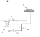
すなわち、図11のように、分岐路13を設けることで、高圧側の高温冷媒を直接(凝縮器、膨張弁を通さずに)低圧側に送り、静電吸着電極1内の冷媒蒸発温度を高温側に制御する方法がある。この方法により、低圧側と高圧側の圧力差を抑制し、静電吸着電極1内の冷媒蒸発温度を膨張、圧縮が無い温度(入熱が無い場合には室温)まで上昇させることができる。しかし、圧縮機7はサイクル内の冷媒を送り出すと同時に吸込んでいるため、この方法においても静電吸着電極1内の冷媒を圧縮することは困難であり、冷媒の蒸発温度を凝縮温度に近い温度まで高温側に制御することは難しい。また、ウエハW処理時のプラズマからの入熱以外に熱源を持たないため、直膨式システムを加熱サイクルに切り換えて、静電吸着電極1を加熱(例えば予備加熱など)することはできない。
That is, as shown in FIG. 11, by providing the
一方、特許文献2に開示された、静電吸着電極内への冷媒供給路にヒータを設置して冷媒を加熱する方法によれば、冷媒の乾き度が調節可能となり、冷却能力の制御が可能となる。しかし、ヒータでは冷媒の圧力を制御することは不可能であるため、冷媒の蒸発温度を制御することはできない。
On the other hand, according to the method of heating a refrigerant by installing a heater in the refrigerant supply path into the electrostatic adsorption electrode disclosed in
本発明の目的は、エッチング処理時のウエハの温度を、広い温度範囲にて制御することが可能なプラズマ処理装置を提供することにある。 An object of the present invention is to provide a plasma processing apparatus capable of controlling the temperature of a wafer during etching processing in a wide temperature range.
本発明の他の目的は、高ウエハバイアス電力の印加による大入熱エッチング時のウエハの温度を、高速、面内均一、かつ広温度範囲にて制御することが可能な静電吸着電極用の温調ユニットを備えたプラズマ処理装置を提供することにある。 Another object of the present invention is for an electrostatic adsorption electrode capable of controlling the temperature of a wafer during high heat input etching by applying a high wafer bias power at a high speed, in-plane uniformity, and in a wide temperature range. It is providing the plasma processing apparatus provided with the temperature control unit.
上記課題を解決するために、本発明のプラズマ処理装置は、試料載置手段に載置された被加工試料をプラズマにて処理するためのプラズマ処理装置において、前記試料載置手段に設けられ蒸発器として機能する冷媒流路と、該冷媒流路の入口と凝縮器の出口との間に接続された第一の膨張弁と、前記冷媒流路の出口と圧縮機の入口との間に接続された第二の膨張弁とを有する冷凍サイクルを備えている、ことを特徴とする。 In order to solve the above problems, a plasma processing apparatus according to the present invention is a plasma processing apparatus for processing a sample to be processed placed on a sample placing means with plasma, and is provided on the sample placing means to evaporate. A refrigerant flow path functioning as a condenser; a first expansion valve connected between the refrigerant flow path inlet and the condenser outlet; and a connection between the refrigerant flow path outlet and the compressor inlet. A refrigeration cycle having a second expansion valve formed.
本発明によれば、高ウエハバイアス電力の印加による大入熱エッチング時のウエハの温度を、広い温度範囲にて制御することが可能な静電吸着電極用の温調ユニットを提供できる。 ADVANTAGE OF THE INVENTION According to this invention, the temperature control unit for electrostatic adsorption electrodes which can control the temperature of the wafer at the time of the high heat input etching by application of high wafer bias electric power in a wide temperature range can be provided.
本発明の他の特徴によれば、高ウエハバイアス電力の印加による大入熱エッチング時のウエハの温度を、高速、面内均一、かつ広温度範囲にて制御することが可能な静電吸着電極用の温調ユニットを備えたプラズマ処理装置を提供することができる。 According to another feature of the present invention, an electrostatic chucking electrode capable of controlling the temperature of a wafer during high heat input etching by applying a high wafer bias power at high speed, in-plane uniformity, and in a wide temperature range. The plasma processing apparatus provided with the temperature control unit for can be provided.
本発明の代表的な実施例によれば、静電吸着電極と圧縮機間の冷媒流路に第二の膨張弁を設けて冷媒の流量を調節することで、静電吸着電極内の冷媒流路において冷媒を圧縮可能とし、冷媒の蒸発温度を高めてウエハの温度を高温側まで制御可能にした。
以下、本発明を実施するための最良の形態を以下に示す。
According to an exemplary embodiment of the present invention, the second expansion valve is provided in the refrigerant flow path between the electrostatic adsorption electrode and the compressor to adjust the flow rate of the refrigerant, so that the refrigerant flow in the electrostatic adsorption electrode can be adjusted. The refrigerant can be compressed in the passage, and the temperature of the wafer can be controlled to the high temperature side by increasing the evaporation temperature of the refrigerant.
The best mode for carrying out the present invention will be described below.
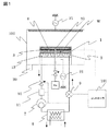
図1は、本発明の第一の実施形態になる温調ユニット付のプラズマ処理装置の構成を示す概略図である。温調ユニット付のプラズマ処理装置の処理室100には、被加工試料であるウエハWを載置するための静電吸着用絶縁薄膜を有する静電吸着電極1と、処理室100を排気する真空排気系20と、処理室100にプラズマ生成用の高周波電力を印加するアンテナ電源21と、処理室100にプラズマ生成用の処理ガスを供給する処理ガス供給系(図示略)と、静電吸着電極1にバイアス用の高周波電力を印加するバイアス電源22と、静電吸着用絶縁薄膜とウエハW裏面との隙間に伝熱ガスを供給するHeガス供給系30とを備えている。静電吸着電極1の内部にはウエハ加熱用ヒータ3及び温度センサ4が内蔵され、静電吸着電極1の下側に配置された電気絶縁材・断熱材からなる基材12内に電極内冷媒流路(以下、単に冷媒流路)2が形成されている。電極内冷媒流路は、冷却用冷媒を供給、排出する入口、出口を有する。この冷媒流路2の入口には冷媒管路を介して第一の膨張弁9が接続され、冷媒流路2の出口には第二の膨張弁10が冷媒管路を介して接続されている。冷媒流路2を蒸発器とし、圧縮機7、凝縮器8、第一の膨張弁9、第二の膨張弁10を含む直膨式の冷凍サイクル(もしくは直膨式ヒートサイクル、以下単に、直膨式冷凍サイクル)が構成されている。第二の膨張弁10と圧縮機7の間の冷媒管路には、冷媒用ヒータ11が配置されている。冷媒用ヒータ11は、例えば2KW〜4KW程度の容量を有する。凝縮器8内へは冷却水が供給される。なお、第一の膨張弁9及び第二の膨張弁10は、何れも可変容量弁で構成されており、その弁開度(絞り)がパルスモータにより制御される。
FIG. 1 is a schematic diagram showing the configuration of a plasma processing apparatus with a temperature control unit according to the first embodiment of the present invention. In a
101は直膨式冷凍サイクルの温度を制御する温度制御システムであり、ウエハの処理条件や温度センサ4の検出値に基づき、ウエハ加熱用ヒータ3や直膨式冷凍サイクルを制御することで、静電吸着電極1のウエハ載置面の温度を制御する。ウエハWはエッチング処理時、プラズマによる大入熱で温度が上昇する。直膨式冷凍サイクルは、後で述べるように、圧縮機7の回転数や、第一の膨張弁9及び第二の膨張弁10の各弁開度、さらには冷媒用ヒータ11の容量を制御することで、プラズマ処理時における冷媒流路2内の冷媒温度、ひいてはウエハの温度を制御する。
直膨式冷凍サイクルは、冷媒が液体から気体に蒸発する際の潜熱を利用して冷却を行い、冷媒の蒸発温度は圧力によって制御可能である。本発明は、蒸発器として機能する冷媒流路2の上流側に位置する第一の膨張弁9と下流側に位置する第二の膨張弁10の少なくとも一方を用いて、冷媒圧力の制御を広範囲に行なうことに特徴がある。
In the direct expansion refrigeration cycle, cooling is performed using latent heat when the refrigerant evaporates from a liquid to a gas, and the evaporation temperature of the refrigerant can be controlled by pressure. The present invention controls refrigerant pressure over a wide range using at least one of the
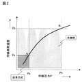
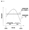
図2に示すように、従来は、電極内冷媒流路をA点(冷媒圧力Pa、冷媒温度Ta)以下の範囲しか制御できなかったが、本発明によれば、B点(冷媒圧力Pb、冷媒温度Tb)の範囲まで、すなわちより高圧、高温度の領域まで、広範囲の制御が可能になる。一例として、A点の冷媒温度Taは20℃、B点の冷媒温度Tbは50℃、B点の冷媒圧力Pbは、2.4MPaである。 As shown in FIG. 2, conventionally, the in-electrode refrigerant flow path could be controlled only within the range of point A (refrigerant pressure Pa, refrigerant temperature Ta) or less, but according to the present invention, point B (refrigerant pressure Pb, A wide range of control is possible up to the range of the refrigerant temperature Tb), that is, up to the region of higher pressure and higher temperature. As an example, the refrigerant temperature Ta at point A is 20 ° C., the refrigerant temperature Tb at point B is 50 ° C., and the refrigerant pressure Pb at point B is 2.4 MPa.
この点に関して、以下に説明を補足する。冷媒圧力の制御方法としては、膨張弁の開度を調節する方法が一般的である。しかし、直膨式の冷凍サイクルでは、冷媒を膨張させて蒸発潜熱により熱を吸収する低圧側(蒸発器側)と、冷媒を圧縮して熱を排熱する高圧側(凝縮器側)が必要となるため、冷媒流路内の冷媒圧力は凝縮器内の冷媒圧力よりも低くなければならない。つまり、圧縮機、凝縮器、膨張弁、蒸発器から成る一般的な直膨式冷凍サイクルでは、冷媒を蒸発器内で圧縮することは原理的に不可能である。したがって、直膨式冷凍サイクルを使用した静電吸着電極用の温調ユニットでは、冷媒の蒸発温度を高温側に制御することが難しく、冷媒の温度制御範囲は低温側に限られ、使用温度域の狭さが問題となっていた。一般的な直膨式冷凍サイクルのように冷媒の圧縮が困難である場合には、R410における冷媒蒸発温度は10℃〜20℃程度までが上限となる。 In this regard, the explanation will be supplemented below. As a method for controlling the refrigerant pressure, a method of adjusting the opening of the expansion valve is common. However, the direct expansion type refrigeration cycle requires a low pressure side (evaporator side) that expands the refrigerant and absorbs heat by latent heat of vaporization, and a high pressure side (condenser side) that compresses the refrigerant and exhausts heat. Therefore, the refrigerant pressure in the refrigerant flow path must be lower than the refrigerant pressure in the condenser. That is, in a general direct expansion refrigeration cycle including a compressor, a condenser, an expansion valve, and an evaporator, it is impossible in principle to compress the refrigerant in the evaporator. Therefore, in a temperature control unit for an electrostatic adsorption electrode that uses a direct expansion refrigeration cycle, it is difficult to control the evaporation temperature of the refrigerant to the high temperature side, and the temperature control range of the refrigerant is limited to the low temperature side. The narrowness was a problem. When it is difficult to compress the refrigerant as in a general direct expansion refrigeration cycle, the upper limit of the refrigerant evaporation temperature in R410 is about 10 ° C to 20 ° C.
そこで、本発明は、静電吸着電極1と圧縮機7間の冷媒流路に第二の膨張弁として機能する流量弁10を設けて冷媒の流量を調節可能にすることで、冷媒流路2において冷媒を圧縮可能とし、冷媒の蒸発温度を高めてウエハWの温度を高温側に制御できるようにした。これにより、冷媒は凝縮器8側と同等まで蒸発温度を高めることが可能となる。例えば、冷媒にR410(ハイドロフルオロカーボン)を使用した場合には、30℃〜50℃程度まで蒸発温度を高温側に制御できる。
Therefore, the present invention provides the
尚、第二の膨張弁として機能する流量弁10を用いて冷媒流路2内の冷媒の蒸発温度を高めた際に、ウエハWと冷媒の温度差が小さくなり、冷媒の蒸発(吸熱)が弱まり、冷媒が完全蒸発せずに圧縮機7に戻る恐れがある。圧縮機7に冷媒が液体状態(非圧縮性状態)で流入した場合、動力の過負荷により圧縮機7の故障が懸念される。そのため、第二の膨張弁10と圧縮機7の間の冷媒管路には、冷媒用ヒータ11などの冷媒加熱手段、またはサクションタンクなどの冷媒気化器を設置し、冷媒を完全蒸発させることが望ましい。
In addition, when the evaporation temperature of the refrigerant in the
本実施例によれば、高ウエハバイアス電力の印加による大入熱エッチング時のウエハの温度を、広温度範囲にて制御することが可能な温調ユニット付のプラズマ処理装置を提供できる。 According to this embodiment, it is possible to provide a plasma processing apparatus with a temperature control unit capable of controlling the temperature of a wafer during high heat input etching by applying a high wafer bias power in a wide temperature range.
図3、図4で本発明の第二の実施形態になる温調ユニット付のプラズマ処理装置を説明する。なお、プラズマ処理装置の構成は、図1に示したものを採用するものとする。 A plasma processing apparatus with a temperature control unit according to the second embodiment of the present invention will be described with reference to FIGS. The configuration of the plasma processing apparatus is the same as that shown in FIG.
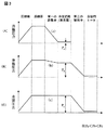
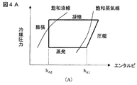
図3に本実施例に基づく冷媒の圧力制御の例を示し、Pa<Pb<Pcとする。図4に直膨式冷凍サイクルのモリエル線図を示す。 FIG. 3 shows an example of refrigerant pressure control based on this embodiment, where Pa <Pb <Pc. FIG. 4 shows a Mollier diagram of the direct expansion refrigeration cycle.
まず、静電吸着電極1の温度を中低温度の領域に制御する場合について、図3の(A)、図4の(A)で説明する。最初に、図3の(A)に示した直膨式冷凍サイクルの特性(a)について説明する。冷媒が圧縮機7により圧縮されて高温液体冷媒となり(ステップ1)、凝縮器8にて冷媒の熱が空冷または水冷によって排熱され(ステップ2)、第一の膨張弁9にて流量が絞られて冷媒圧力(冷媒蒸発温度)が低下し(ステップ3)、電極内冷媒流路2内で冷媒が蒸発し(ステップ4)、潜熱にて静電吸着電極1上のウエハの熱を吸収する。このとき、一例として、第一の膨張弁9の開度は約50%である。一方、第二の膨張弁10は全開状態にあり膨張弁としては機能していない。冷媒の温度は、凝縮器8の入口で60℃、静電吸着電極1の冷媒流路2の入口で−20℃〜20℃程度である。従って、静電吸着電極1は中低温度の領域で制御される。
First, the case where the temperature of the
上記特性は一般的な直膨式冷凍サイクルの特性と同じである。図4の(A)は図3の(A)に対応するものであり、圧縮機7、凝縮器8、膨張弁9、冷媒流路2(蒸発器)にてそれぞれ圧縮、凝縮、膨張、蒸発が行われ、冷媒流路2にてhA1とhA2の差のエンタルピ[KJ/Kg]が冷媒に吸収される。
The above characteristics are the same as those of a general direct expansion refrigeration cycle. 4A corresponds to FIG. 3A, and compression, condensation, expansion, and evaporation are respectively performed in the
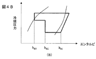
次に、静電吸着電極1の温度を比較的高い温度領域に制御する場合について、図3の(B)、図4の(B)で説明する。図3の(B)に示した特性(b)は、第一の膨張弁9、第二の膨張弁10の双方により、冷媒圧力を制御するものである。第一の膨張弁9での流量の絞りを少なくし、冷媒の圧力低下は気化開始圧力(圧縮によって液化していた冷媒が蒸発し始める圧力)程度に留めて冷媒流路2内の冷媒蒸発温度を高温に保つ。そして、第二の膨張弁10にて冷媒圧力を本格的に低下させ、冷媒流路2で蒸発不十分であった冷媒を冷媒用ヒータ11にて完全蒸発させる。これにより、冷媒流路2内での冷媒圧力を特性(a)よりも高圧側に制御可能となり、冷媒蒸発温度を高温に制御できる。一例として、第一の膨張弁9の開度が約50%〜90%であり、第二の膨張弁10は低開度状態にある。冷媒の温度は、凝縮器8の入口で60℃、冷媒流路2の入口で50℃、冷媒用ヒータ11の入口で−20℃〜20℃である。従って、静電吸着電極1は比較的高い温度に制御される。
Next, the case where the temperature of the
図4の(B)は、図3の(B)に示した直膨式冷凍サイクルのサイクルを示し、第一の膨張弁9、第二の膨張弁10で飽和液線以下の気化圧力領域内で冷媒流路2内の冷媒圧力を上昇させて、冷却を行っている。エンタルピがhB2とhB3で示される区間は、冷媒流路2内の冷媒の蒸発領域を示し、エンタルピがhB1とhB2で示される区間は、冷媒用ヒータ11における冷媒の蒸発領域を示している。すなわち、蒸発温度が上昇してウエハWと冷媒の温度差が小さくなり、吸収エンタルピがhB2とhB3の差に留まった(冷媒が完全に気化しない)ため、第二の膨張弁10にて冷媒圧力を低下させ、冷媒用ヒータ11にてhB1とhB2の差のエンタルピを吸収して冷媒が完全蒸発する例を示している。
FIG. 4B shows the cycle of the direct expansion refrigeration cycle shown in FIG. 3B, and the
尚、吸収したエンタルピ[kJ/kg]と冷媒の質量流量[kg/s]の積により、直膨式冷凍サイクルの冷却能力[kW]が算出できる。 The cooling capacity [kW] of the direct expansion refrigeration cycle can be calculated from the product of the absorbed enthalpy [kJ / kg] and the mass flow rate [kg / s] of the refrigerant.
次に、静電吸着電極1の温度を高くする(加熱サイクル)場合について、図3の(C)で説明する。このときは、第一の膨張弁9の開度を全開とし、第二の膨張弁10に圧力低下機能を持たせる。これにより、図3の(C)に示した特性(c)のように、凝縮器8内と冷媒流路2内の冷媒圧力を同等にすることが可能である。つまり、冷媒用ヒータ11の熱で冷媒を蒸発させて、その冷媒を冷媒流路2内で圧縮して排熱させることで、冷媒流路2をヒータとして機能させる。これにより、プラズマ処理開始前の温調時などに静電吸着電極1を加熱するデフロストサイクルの構築が可能となる。一例として、冷媒の温度は、冷媒流路2の入口で50℃〜60℃である。なお、加熱サイクルの場合、凝縮器8内への冷却水の供給は停止する。
Next, the case where the temperature of the
本実施例によれば、圧縮機7の回転数や、第一の膨張弁9及び第二の膨張弁10の各開度を制御することで、プラズマ処理時、特に、高ウエハバイアス電力の印加による大入熱エッチング時のウエハの温度を、高速、かつ広温度範囲にて制御することが可能な静電吸着電極用の温調ユニットを備えたプラズマ処理装置を提供することができる。
According to the present embodiment, by controlling the rotation speed of the
図5(図5A〜図5D)に、本発明の第三の実施形態として、第一の実施形態の温調ユニット付プラズマ処理装置における薄肉円筒流路構造に検討を加えた例を示す。直膨式の冷凍サイクルでは、冷媒の圧力を調節することにより蒸発温度を秒単位で制御可能である。この特性を用いてウエハWの温度を高速に制御するためには、ウエハWと冷媒流路2間の熱通過損失を低減しなければならない。つまり、ウエハWを設置する静電吸着電極1の低熱容量化が必要となる。静電吸着電極1の熱容量低減には、質量の低減、または構成材料を低熱容量材料に変更するなどの手段が考えられる。しかし、構成材料の変更は熱特性以外にも電気特性や含有成分(チャンバー内の汚染に影響)等の他の要因も考慮しなければならないため、容易ではない。
FIG. 5 (FIGS. 5A to 5D) shows an example in which a thin cylindrical channel structure in the plasma processing apparatus with a temperature control unit of the first embodiment is studied as a third embodiment of the present invention. In the direct expansion type refrigeration cycle, the evaporation temperature can be controlled in seconds by adjusting the pressure of the refrigerant. In order to control the temperature of the wafer W at high speed using this characteristic, the heat passage loss between the wafer W and the
したがって、熱容量の低減には静電吸着電極1の質量の低減が現実的である。ただし、質量の低減は構成材料の厚みを薄くすることになり、機械的な強度(剛性)を下げることになる。静電吸着電極1の吸着力は、吸着面の状態により大きく左右されることから、剛性の低下による変形量の増加が懸念される。
Therefore, it is realistic to reduce the mass of the
更に、直膨式の冷凍サイクルには冷媒圧力が高い特徴がある。R410(ハイドロフルオロカーボン)を例に挙げると、冷媒を40℃で蒸発させるためには、冷媒圧力を約2.4MPaまで上昇させる必要がある。これは従来の液体冷媒方式の約5倍に相当する。したがって、直膨式の冷凍サイクルを採用し、ウエハの温度を高速に制御するためには、上記のようなトレードオフの問題を解決しなければならない。 Furthermore, the direct expansion type refrigeration cycle is characterized by high refrigerant pressure. Taking R410 (hydrofluorocarbon) as an example, in order to evaporate the refrigerant at 40 ° C., it is necessary to increase the refrigerant pressure to about 2.4 MPa. This corresponds to about five times the conventional liquid refrigerant system. Therefore, in order to employ a direct expansion type refrigeration cycle and control the temperature of the wafer at high speed, the above trade-off problem must be solved.
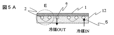
そこで、静電吸着電極1の冷媒流路2を、薄肉円筒構造とすることで、冷媒圧力による変形を薄肉円筒の微小変形に留めるようにした。図5Aは、静電吸着電極1の縦断面図、図5Bは基材12に埋設された冷媒流路2部分の横断面図である。冷媒流路2は、円形断面で同心円状の複数の環状流路2Aと、断面が円形の連絡流路2Bとで構成され、最外周の環状流路2Aに冷媒供給口5が接続され、最内周の環状流路2Aに媒排出口6が接続されている。連絡流路2Bは、図5Bに矢印で示したように隣接する環状流路2Aを接続している。製造方法としては、予め、冷媒流路2を構成する薄肉円筒を静電吸着電極1に接合あるいは接着し、それらの上に、例えばテフロン(登録商標)などの樹脂をモールドして基材12を形成する。
In view of this, the
図5Bにおいて、図右側の冷媒供給口5から電極内冷媒流路2の最外周の環状流路2Aに流入した冷媒は、二分され、図左側の連絡流路2Bで合流し、内側の環状流路2Aに流入し、最後に、最内周の環状流路2Aから冷媒排出口6を経て、電極内冷媒流路2の外へ流出する。
In FIG. 5B, the refrigerant that has flowed from the
本発明における冷媒流路2を構成する薄肉円筒の材質は設計上任意に設定可能であるが、静電吸着電極1と冷媒流路2を構成する薄肉円筒が別材料の場合には、熱膨張係数の差による熱応力が発生するため、両者は同一材料で構成することが望ましい。使用材料としては例えばアルミニウムなどが考えられる。また、薄肉円筒の肉厚は、加工性の観点からも0.3mm〜3mm程度が望ましい。更に、冷媒流路2の内壁に冷媒の熱伝達促進用として、冷媒流路2の幅に対して高さが2〜10%程度の凹凸を設けるとよい。
The material of the thin cylinder constituting the
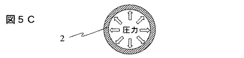
静電吸着電極の冷媒流路を薄肉円筒構造としたことにより、図5Cに示したように、冷媒の圧縮による高圧力条件下でも、静電吸着電極1の変形を抑制し、ウエハの静電吸着力を維持できる。また、電極構造の簡略化が可能となるため、静電吸着電極1を低熱容量化(低質量化)し、温度制御性の向上を図れる。
Since the refrigerant flow path of the electrostatic adsorption electrode has a thin-walled cylindrical structure, as shown in FIG. 5C, deformation of the
例えば、一般的なアルミニウム材料であるA5052で考えた場合、凹溝を有するプレートと平板とをボルト結合して矩形断面の冷媒流路を形成した従来の電極構造を想定して、φ360mm、厚さ30mm、外周部固定の部材に2.5MPaの冷媒圧力が加わった場合、部材には最大で230μm(中心部)の変形が生じる。これに対し、本発明の薄肉円筒構造では、例えばA5052の1/4インチ管(肉厚0.8mm)構造で計算しても、冷媒流路を構成する円筒径の変形は0.5μmに収まる。しかも、冷媒流路を構成する円筒径の変形は、静電吸着電極1には実質的な影響を及ぼさず、静電吸着電極1は良好な吸着力を維持できる。
For example, in the case of A5052, which is a general aluminum material, assuming a conventional electrode structure in which a refrigerant channel having a rectangular cross section is formed by bolting a plate having a concave groove and a flat plate, a thickness of φ360 mm, a thickness When a refrigerant pressure of 2.5 MPa is applied to a member fixed to the outer peripheral portion of 30 mm, the member is deformed by a maximum of 230 μm (center portion). On the other hand, in the thin-walled cylindrical structure of the present invention, the deformation of the cylindrical diameter constituting the refrigerant flow path is within 0.5 μm even when calculated with, for example, the
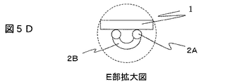
さらに、薄肉円筒構造では冷媒流路2を静電吸着電極1と独立して設置することが可能となるため、静電吸着電極1内において冷却に不要な流路を断熱して(静電吸着電極1から離して)、ウエハW面内の温度均一性を向上することができる。このような例を図5Dで説明する。図5Dは図5AのE部の拡大図である。
Furthermore, since the
まず、図5Bでは、冷媒が冷媒供給口5から冷媒排出口6まで流れる間に環状流路の他に連絡流路が必要となるが、局所的に設置される連絡流路はウエハの温度均一性の観点から見た場合には不要である。こうした場合、図5Dに示したように、連絡流路2Bを静電吸着電極1から独立して設置することで、ウエハの面内温度を均一に保つことができる。すなわち、連絡流路2Bを環状流路2Aよりも下側、換言すると静電吸着用絶縁薄膜から離れた基材12の内部側に配置し、隣接する2つの環状流路2Aを接続する。このような立体的な接合構造の採用により、冷媒流路を静電吸着電極と独立して設置することが可能となるため、静電吸着電極内において冷却に不要な流路を断熱し、ウエハ面内の温度差を低減することができる。
First, in FIG. 5B, while the refrigerant flows from the
尚、図5の冷媒供給口5と冷媒排出口6はそれぞれの設置位置が逆であってもよい。
Note that the
また、静電吸着電極の冷媒流路を薄肉円筒構造とすることで、冷媒を圧縮する高圧力条件においても、静電吸着電極の変形を抑制し、ウエハの静電吸着力を維持できる。また、電極流路構造の簡略化が可能となるため、静電吸着電極を低熱容量化(低質量化)し、温度制御性の向上を図れる。さらに、冷媒流路を静電吸着電極と独立して設置することが可能となるため、静電吸着電極内において冷却に不要な流路を断熱し、ウエハ面内の温度差を低減することができる。 In addition, since the refrigerant flow path of the electrostatic adsorption electrode has a thin cylindrical structure, deformation of the electrostatic adsorption electrode can be suppressed and the electrostatic adsorption force of the wafer can be maintained even under high pressure conditions in which the refrigerant is compressed. Moreover, since the electrode channel structure can be simplified, the electrostatic adsorption electrode can be reduced in heat capacity (lower mass), and temperature controllability can be improved. Furthermore, since the refrigerant flow path can be installed independently of the electrostatic adsorption electrode, it is possible to insulate the flow path unnecessary for cooling in the electrostatic adsorption electrode and reduce the temperature difference in the wafer surface. it can.
このように、本実施例によれば、高ウエハバイアス電力の印加による大入熱エッチング時のウエハの温度を、高速、面内均一、かつ広温度範囲にて制御することが可能な静電吸着電極用の温調ユニットを備えたプラズマ処理装置を提供することができる。 As described above, according to the present embodiment, the electrostatic adsorption capable of controlling the temperature of the wafer during high heat input etching by applying a high wafer bias power at high speed, in-plane uniformity, and in a wide temperature range. A plasma processing apparatus including a temperature control unit for electrodes can be provided.
図6(図6A、図6B)で、本発明の第四の実施形態を述べる。図6Aは、静電吸着電極1の縦断面図、図6Bは基材12に設けられた冷媒流路2部分の横断面図である。
まず、静電吸着電極1に高周波電力を印加した場合を考えると、静電吸着電極1の裏面にてプラズマが生成される恐れがある。このため、前記裏面には電気的絶縁体からなる基材12の設置が必要となる。絶縁体からなる基材12の材質としては、例えばテフロンなどが望ましい。テフロンは熱伝導率が低いため、断熱材としての効果も期待できる。
A fourth embodiment of the present invention will be described with reference to FIG. 6 (FIGS. 6A and 6B). FIG. 6A is a longitudinal sectional view of the
First, considering the case where high frequency power is applied to the
図6により、薄肉円筒流路構造にてウエハの面内温度分布を制御する方法について示す。第三の実施形態で述べたように冷媒流路2を薄肉円筒構造とし、静電吸着電極1の裏面を絶縁・断熱材からなる基材12で覆うことで、各流路間がそれぞれ断熱される。本実施例では、図6Bに示すように、基材12に同心円状の複数の環状流路2A1、2A2、2A3が独立して形成されており、夫々、同図右側部に半径方向に一列に配列された冷媒供給口(i)、(ii)、(iii)が接続されている。また、各環状流路には、夫々、同図左側部に半径方向に一列に配列された冷媒排出口(i’)、(ii’)、(iii’)が接続されている。各環状流路2A1、2A2、2A3は、夫々独立した直膨式冷凍サイクル40、41、42の一部として構成される。換言すると、この実施例では、連絡流路は不要である。
FIG. 6 shows a method of controlling the in-plane temperature distribution of the wafer with a thin cylindrical channel structure. As described in the third embodiment, the
図6Aに示すように、各直膨式冷凍サイクルの環状流路に流す冷媒の蒸発温度をそれぞれ制御する、例えば図3に示したように制御することにより、ウエハの面内温度分布を任意に制御可能となる。 As shown in FIG. 6A, by controlling the evaporation temperature of the refrigerant flowing through the annular flow path of each direct expansion refrigeration cycle, for example, as shown in FIG. Control becomes possible.
本実施例によれば、冷媒流路2を薄肉円筒構造とすることで、冷媒圧力による変形を薄肉円筒の微小変形に留めることができる。この構造により、冷媒を圧縮する高圧力条件においても、静電吸着電極1の変形を抑制できる。これにより、高ウエハバイアス電力の印加による大入熱エッチング時のウエハの温度を、高速、面内均一、かつ広温度範囲にて制御することが可能な静電吸着電極用の温調ユニットを提供することができる。
According to the present embodiment, the
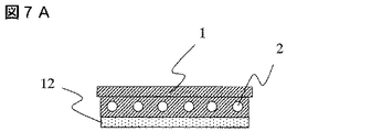
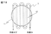
図7(図7A、図7B)で、本発明の第五の実施形態として静電吸着電極内1に薄肉円筒流路を埋め込んだ例を述べる。図7Aは、静電吸着電極1の縦断面図、図7Bは冷媒流路2部分の構成を示す静電吸着電極の背面図である。
7 (FIG. 7A, FIG. 7B), an example in which a thin cylindrical channel is embedded in the
既に述べた実施例では、冷媒流路2を設ける基材12と静電吸着電極1とを別部材とし、例えば溶着や接着などで接合している。しかし、冷媒流路2の構造は、これに限定されるものではない。
In the embodiment already described, the
例えば、図7に示すように、静電吸着電極1の中に冷媒流路2となる薄肉円筒流路を、かしめなどの方法により埋め込む一体的構造も考えられる。静電吸着電極1と電気絶縁材・断熱材からなる基材12とは、例えば溶着や接着などで接合される。なお、図7の例では、冷媒流路2は連続した単一の流路として構成されている。
本実施例でも、高ウエハバイアス電力の印加による大入熱エッチング時のウエハの温度を、高速、面内均一、かつ広温度範囲にて制御することが可能な静電吸着電極用の温調ユニットを提供できる。
For example, as shown in FIG. 7, an integral structure in which a thin cylindrical flow path that becomes the
In this embodiment as well, the temperature control unit for the electrostatic chucking electrode can control the temperature of the wafer during high heat input etching by applying high wafer bias power at high speed, in-plane uniformity, and in a wide temperature range. Can provide.
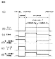
次に、本発明の第六の実施形態として、薄膜のエッチング処理を行う場合のプロセス例を、図8のプロセスのタイムチャートを用いて説明する。この実施例は、図1の直膨式冷凍サイクルを備えたプラズマ処理装置と図5の薄肉円筒流路構造を用いて、実際にウエハW上に形成された薄膜のエッチング処理を行う場合のプロセスを想定した例である。 Next, as a sixth embodiment of the present invention, a process example when performing a thin film etching process will be described with reference to a time chart of the process of FIG. This embodiment uses a plasma processing apparatus equipped with the direct expansion type refrigeration cycle of FIG. 1 and a thin cylindrical flow channel structure of FIG. 5 to perform a process for etching a thin film actually formed on a wafer W. This is an example assuming that
プラズマ処理を行なう薄膜としては、SiO2、Si3N4、SiOC、SiOCH、SiCのいずれか1種類を主成分とする単一の膜、または2種類以上の膜種にて構成される多層膜などが考えられる。 As a thin film to be subjected to plasma treatment, a single film mainly composed of any one of SiO 2 , Si 3 N 4 , SiOC, SiOCH, and SiC, or a multilayer film composed of two or more kinds of films. And so on.
図8の(a)は、プラズマ処理装置によるウエハWの搬送、及び処理プロセスの概要を示し、(b)は、バイアス電源22からのバイアス印加のタイミング、(c)は直膨式冷凍サイクルの圧縮機の動作状態、(d)は第一の膨張弁9の開度、(e)はウエハ用ヒータの電源のオンオフ、(f)は第二の膨張弁10の開度を示している。
FIG. 8A shows an outline of the transfer of the wafer W and the processing process by the plasma processing apparatus, FIG. 8B shows the timing of bias application from the
ウエハWは、図示しない被処理体搬送装置から処理室100に搬入され、静電吸着電極1上に載置、固定される。この状態で、静電吸着電極1等の温度調整が行なわれる。プロセス間に温調を行う必要がある場合、第二の膨張弁10の制御にて直膨式システムの蒸発温度を高めて、冷却能力を低下させ、その状態においてウエハ用ヒータ3を用いて静電吸着電極1を加熱することで、ウエハWを予備加熱する。このとき、圧縮機7は低速回転、第一の膨張弁9は高開度、第二の膨張弁10は低開度、ウエハ用ヒータ3電源はオン状態に、それぞれ制御される。また、プロセス間の温調の他の方法として、第二の膨張弁10、冷媒用ヒータ11の制御にて直膨式システムを加熱サイクルに切り替え、静電吸着電極1を予備加熱してもよい。この場合には、冷媒用ヒータ11を熱源として利用する。
The wafer W is carried into the
次いで、ウエハWのエッチングに必要なプロセスガスが図示しない処理ガス供給系より供給され、真空排気系20により処理室100は所定の処理圧力に調整される。次に、アンテナ電源21及びバイアス電源22の電力供給と、図示されない磁場形成手段の作用により処理室100内にプラズマが生成され、静電吸着電極1上のウエハのエッチングが開始する。
Next, a process gas necessary for etching the wafer W is supplied from a processing gas supply system (not shown), and the
プロセス中のウエハ温度の制御は、温度センサ4からの温度情報をモニタしながら温度制御システム101にてフィードバック制御を行い、圧縮機7、第一の膨張弁9、第二の膨張弁10、ウエハ用ヒータ3を調節して、冷媒の流量、蒸発温度、及びウエハ用ヒータ3の加熱量を調節する。
The wafer temperature during the process is controlled by feedback control by the
この際、圧縮機7、第一の膨張弁9、第二の膨張弁10にて冷媒流路2内の冷媒蒸発温度を例えば−20〜50℃の広範囲で制御することが可能である。例えばあるプロセスステップにおけるプラズマ入熱が大きいときは、圧縮機7の回転数を高くし、第一の膨張弁9は低開度、第二の膨張弁10は全開状態とし、ウエハWに対する冷却能力を大きくする。プラズマ入熱が小さいときは、圧縮機7の回転数を低くし、第一の膨張弁9は高開度、第二の膨張弁10は中開度とし、ウエハWに対する冷却能力を小さくする。
At this time, the refrigerant evaporating temperature in the
このように、本発明はウエハWに3W/cm2以上の高周波電力を印加するような大入熱が生じる加工条件に対応し、アスペクト比が15以上となる高アスペクトの深孔加工を行なう際にも有効である。 As described above, the present invention corresponds to processing conditions in which high heat input is applied to the wafer W so as to apply a high frequency power of 3 W / cm 2 or more, and when performing high aspect deep hole processing with an aspect ratio of 15 or more. Also effective.
また、図6に示したような、各流路間に断熱部材の設置された独立した複数の冷媒流路2を採用し、各々の冷媒流路2に流す冷媒の蒸発温度を制御することで、静電吸着電極1の面内温度分布を制御することも可能である。これにより、高ウエハバイアス電力の印加による大入熱エッチング条件においても、ウエハWの面内全体で高速かつ広い温度域の温度制御が可能となる。
In addition, by adopting a plurality of independent
このようなプロセスを経てエッチングが完了し、電力、磁場及びプロセスガスの供給が停止される。 Etching is completed through such a process, and the supply of power, magnetic field and process gas is stopped.
尚、プラズマ処理装置のプラズマの生成手段が、ウエハWに対面して配置された電極にウエハWに印加されるのとは別の高周波電力を印加する方式、誘導結合方式、磁場と高周波電力の相互作用方式、静電吸着電極1に高周波電力を印加する方式のいずれの方式であっても、本発明が有効であることは言うまでもない。
Note that the plasma generating means of the plasma processing apparatus applies a high frequency power different from that applied to the wafer W to the electrode disposed facing the wafer W, an inductive coupling method, a magnetic field and a high frequency power. Needless to say, the present invention is effective regardless of the interaction method or the method of applying high-frequency power to the
次に、本発明の第七の実施形態を、図9、図10を用いて説明する。
直膨式システムでは冷媒が冷媒流路2内で熱を吸収して蒸発しながら流れているため、液体から気体への相変化に伴い冷媒の熱伝達率が変化する。これにより、静電吸着電極1の表面温度、ひいてはウエハWの温度を面内均一にすることが困難となる。そのため、冷媒流路2は流路の断面積を最適化し、冷媒の流速を制御して、冷媒流路2内で冷媒の熱伝達率が一定となるようにする必要がある。
Next, a seventh embodiment of the present invention will be described with reference to FIGS.
In the direct expansion system, since the refrigerant flows while absorbing and evaporating heat in the
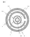
図9に流路断面積を最適化した例を示す。また、図10に冷媒の熱伝達特性を示す。
例えば、R410冷媒を使用して静電吸着電極1を冷却する際には、かわき度が低い領域と高い領域で熱伝達率が低下するため、上記両領域で流路の断面積を小さくして冷媒の流速を高めることで、熱伝達率の低下を抑制できる。すなわち、図9に示すように、中間の環状流路2−2の流路断面積を、その外側及び内側の環状流路2−1、2−3の各流路断面積よりも大きくする。
FIG. 9 shows an example in which the channel cross-sectional area is optimized. FIG. 10 shows the heat transfer characteristics of the refrigerant.
For example, when the
尚、かわき度が高い領域において熱伝達率が低下する原因はドライアウト(液膜の消失)であり、この領域を使用せずに静電吸着電極1を冷却する場合には、冷媒流路2の断面積は、入口から出口に向かって連続的に拡大する構造とすればよい。そして蒸発不十分であった冷媒は、冷媒用ヒータ11等によって完全蒸発させればよい。
Incidentally, the cause of the decrease in the heat transfer coefficient in the region where the degree of cuteness is low is dryout (disappearance of the liquid film). When the
上記のように、冷媒流路2の断面積を最適化した構造では、冷媒流路2内を流れる冷媒のかわき度が毎回同様でなければならない。つまり、冷媒の蒸発温度を高めた際に、冷媒の吸熱量が減少し、冷媒のかわき度(蒸発具合)が変化するようなことがあってはならない。そのため、例えば冷媒の蒸発温度を上昇させて冷却能力を低下させる際には、圧縮機7の回転数を低下させて冷媒循環量を減らし、蒸発温度(冷媒圧力)は第二の膨張弁10によって制御すればよい。入熱に応じて冷媒循環量を制御すれば、冷媒流路2内において、常に同様のかわき度状態を再現でき、静電吸着電極1の面内温度を均一に保つことができる。
As described above, in the structure in which the cross-sectional area of the
尚、本発明の薄肉円筒流路構造は、冷却能力向上のため冷媒の流量が増加し、冷媒の圧力増加が課題となりつつある液体冷媒方式にも有効であることは言うまでもない。 Needless to say, the thin-walled cylindrical channel structure of the present invention is also effective for a liquid refrigerant system in which the flow rate of the refrigerant is increased to improve the cooling capacity and the increase in the pressure of the refrigerant is becoming a problem.
また、本発明が提案するプラズマ処理装置における温調ユニットは、上記の実施例のみに限定されるものではない。アッシング装置、スパッタ装置、イオン注入装置、レジスト塗布装置、プラズマCVD装置などのウエハの載置手段であって、処理時のプラズマ入熱等に対してウエハの温度制御を必要とする温調装置にも、本発明の転用が可能である。また、ウエハの処理装置としては、真空雰囲気でウエハを処理する真空処理装置のみならず、大気雰囲気でウエハを処理する処理装置にも本発明を適用できる。また、ウエハの載置手段に限らず、処理時のプラズマ入熱等に対して温度制御を必要とする処理室壁構造等の温調装置にも、本発明の転用が可能である。 Moreover, the temperature control unit in the plasma processing apparatus proposed by the present invention is not limited to the above embodiment. Wafer mounting means such as ashing equipment, sputtering equipment, ion implantation equipment, resist coating equipment, plasma CVD equipment, etc., and temperature control equipment that requires temperature control of the wafer against plasma heat input during processing Also, the diversion of the present invention is possible. Further, as the wafer processing apparatus, the present invention can be applied not only to a vacuum processing apparatus that processes a wafer in a vacuum atmosphere but also to a processing apparatus that processes a wafer in an air atmosphere. Further, the present invention can be applied not only to the wafer mounting means but also to a temperature control device such as a processing chamber wall structure that requires temperature control for plasma heat input during processing.
さらに、ウエハ等の被加工試料を載置する試料載置手段は、静電吸着電極に限定されるものではなく、例えば真空吸着その他の被加工試料を保持する機能を備えたものであっても良い。 Furthermore, the sample mounting means for mounting a workpiece sample such as a wafer is not limited to the electrostatic chucking electrode, and may be, for example, a device having a function of holding a workpiece sample by vacuum suction or the like. good.
1…静電吸着電極、2…冷媒流路、2A…環状流路、2B…連絡流路、3…ウエハ用ヒータ、4…温度センサ、5…冷媒供給口、6…冷媒排出口、7…圧縮機、8…凝縮器、9…第一の膨張弁、10…第二の膨張弁、11…冷媒用ヒータ、12…絶縁・断熱材からなる基材、13…分岐路、20…真空排気系、21…アンテナ電源、22…バイアス電源、30…Heガス供給系、100…処理室、101…温度制御システム、W…ウエハ。
DESCRIPTION OF
Claims (10)
前記試料載置手段に設けられ蒸発器として機能する冷媒流路と、該冷媒流路の入口と凝縮器の出口との間に接続された第一の膨張弁と、前記冷媒流路の出口と圧縮機の入口との間に接続された第二の膨張弁とを有する冷凍サイクルを備えている、ことを特徴とするプラズマ処理装置。 In a plasma processing apparatus for processing a sample to be processed placed on a sample placing means with plasma,
A refrigerant channel provided in the sample mounting means and functioning as an evaporator; a first expansion valve connected between an inlet of the refrigerant channel and an outlet of the condenser; and an outlet of the refrigerant channel A plasma processing apparatus comprising a refrigeration cycle having a second expansion valve connected between an inlet of a compressor.
前記プラズマ処理装置が、真空排気手段を有する真空容器へガス導入手段により導入された原料ガスをプラズマ化し、該プラズマにて被加工試料の表面処理を行うプラズマ処理装置であり、
前記試料載置手段が静電吸着電極である、ことを特徴とするプラズマ処理装置。 In claim 1,
The plasma processing apparatus is a plasma processing apparatus for converting a raw material gas introduced by a gas introduction unit into a vacuum vessel having a vacuum evacuation unit, and performing a surface treatment of a sample to be processed with the plasma,
The plasma processing apparatus, wherein the sample mounting means is an electrostatic adsorption electrode.
前記冷媒流路が薄肉円筒構造であり、該冷媒流路が前記静電吸着電極に接合されている、ことを特徴とするプラズマ処理装置。 In claim 2,
The plasma processing apparatus, wherein the refrigerant flow path has a thin cylindrical structure, and the refrigerant flow path is joined to the electrostatic adsorption electrode.
前記静電吸着電極の下側に配置された電気絶縁材・断熱材からなる基材内に前記冷媒流路が配設されている、ことを特徴とするプラズマ処理装置。 In claim 3,
The plasma processing apparatus, wherein the refrigerant flow path is disposed in a base material made of an electrical insulating material and a heat insulating material disposed below the electrostatic adsorption electrode.
前記静電吸着電極と前記冷媒流路が同一材料で構成されている、ことを特徴とするプラズマ処理装置。 In claim 2,
The plasma processing apparatus, wherein the electrostatic adsorption electrode and the coolant channel are made of the same material.
前記試料設置手段に設けられた冷媒流路を蒸発器として、圧縮機、凝縮器、第一の膨張弁、及び前記蒸発器と前記圧縮機との間に設置された第二の膨張弁を含む冷凍サイクルが構成され、
前記第二の膨張弁と前記圧縮機の間に、冷媒用ヒータが配置されている、ことを特徴とするプラズマ処理装置。 In a plasma processing apparatus for processing a sample to be processed placed on a sample placing means with plasma,
Using the refrigerant flow path provided in the sample installation means as an evaporator, a compressor, a condenser, a first expansion valve, and a second expansion valve installed between the evaporator and the compressor The refrigeration cycle is configured,
A plasma processing apparatus, wherein a refrigerant heater is disposed between the second expansion valve and the compressor.
前記プラズマ処理装置が、真空排気手段を有する真空容器へガス導入手段により導入された原料ガスをプラズマ化し、該プラズマにて被加工試料の表面処理を行うプラズマ処理装置であり、
前記試料載置手段が静電吸着電極である、ことを特徴とするプラズマ処理装置。 In claim 6,
The plasma processing apparatus is a plasma processing apparatus for converting a raw material gas introduced by a gas introduction unit into a vacuum vessel having a vacuum evacuation unit, and performing a surface treatment of a sample to be processed with the plasma,
The plasma processing apparatus, wherein the sample mounting means is an electrostatic adsorption electrode.
前記静電吸着電極の下側に配置された電気絶縁材・断熱材からなる基材内に前記冷媒流路が配設され、
前記試料載置手段の冷媒流路が薄肉円筒構造である、ことを特徴とするプラズマ処理装置。 In claim 7,
The refrigerant flow path is disposed in a base material composed of an electrical insulating material and a heat insulating material disposed on the lower side of the electrostatic adsorption electrode,
The plasma processing apparatus, wherein the coolant passage of the sample mounting means has a thin cylindrical structure.
前記試料載置手段が静電吸着電極であり、該静電吸着電極に冷凍サイクルの蒸発器を構成する冷媒流路が接合され、
前記冷媒流路内において冷媒が膨張及び圧縮可能に構成されている、ことを特徴とする試料処理装置。 In a sample processing apparatus for mounting a sample to be processed on a sample mounting means having a temperature control function and performing surface treatment of the sample to be processed,
The sample mounting means is an electrostatic adsorption electrode, and a refrigerant flow path constituting an evaporator of a refrigeration cycle is joined to the electrostatic adsorption electrode,
The sample processing apparatus, wherein the refrigerant is configured to be able to expand and compress in the refrigerant flow path.
前記冷媒流路は、同心円状に設けられた複数の環状流路で構成され、中間に位置する前記環状流路の流路断面積を、外側及び内側に位置する前記環状流路の流路断面積よりも大きく構成した、ことを特徴とする試料処理装置。 In claim 9,
The refrigerant flow path is composed of a plurality of concentric circular flow paths, and the cross-sectional area of the annular flow path located in the middle is divided between the flow paths of the annular flow paths positioned outside and inside. A sample processing apparatus characterized by being configured to be larger than the area.
Priority Applications (1)
| Application Number | Priority Date | Filing Date | Title |
|---|---|---|---|
| JP2011223960A JP5416748B2 (en) | 2011-10-11 | 2011-10-11 | Plasma processing equipment |
Applications Claiming Priority (1)
| Application Number | Priority Date | Filing Date | Title |
|---|---|---|---|
| JP2011223960A JP5416748B2 (en) | 2011-10-11 | 2011-10-11 | Plasma processing equipment |
Related Parent Applications (1)
| Application Number | Title | Priority Date | Filing Date |
|---|---|---|---|
| JP2007136870A Division JP4898556B2 (en) | 2007-05-23 | 2007-05-23 | Plasma processing equipment |
Publications (2)
| Publication Number | Publication Date |
|---|---|
| JP2012028811A true JP2012028811A (en) | 2012-02-09 |
| JP5416748B2 JP5416748B2 (en) | 2014-02-12 |
Family
ID=45781284
Family Applications (1)
| Application Number | Title | Priority Date | Filing Date |
|---|---|---|---|
| JP2011223960A Active JP5416748B2 (en) | 2011-10-11 | 2011-10-11 | Plasma processing equipment |
Country Status (1)
| Country | Link |
|---|---|
| JP (1) | JP5416748B2 (en) |
Cited By (7)
| Publication number | Priority date | Publication date | Assignee | Title |
|---|---|---|---|---|
| KR20140114747A (en) * | 2013-03-19 | 2014-09-29 | 가부시키가이샤 히다치 하이테크놀로지즈 | Plasma processing device and plasma processing method |
| KR20180090204A (en) | 2017-02-02 | 2018-08-10 | 도쿄엘렉트론가부시키가이샤 | Processing apparatus for processing target object |
| KR20180090206A (en) | 2017-02-02 | 2018-08-10 | 도쿄엘렉트론가부시키가이샤 | Processing apparatus for processing target object |
| KR20190009713A (en) | 2017-07-19 | 2019-01-29 | 도쿄엘렉트론가부시키가이샤 | Processing apparatus for target object and inspection method for processing apparatus |
| KR20190011686A (en) | 2017-07-25 | 2019-02-07 | 도쿄엘렉트론가부시키가이샤 | Substrate processing apparatus, and operation method for substrate processing apparatus |
| CN111048437A (en) * | 2018-10-15 | 2020-04-21 | 东京毅力科创株式会社 | Temperature control system and temperature control method |
| US11060770B2 (en) | 2018-02-13 | 2021-07-13 | Tokyo Electron Limited | Cooling system |
Families Citing this family (1)
| Publication number | Priority date | Publication date | Assignee | Title |
|---|---|---|---|---|
| JP7365815B2 (en) | 2019-08-09 | 2023-10-20 | 東京エレクトロン株式会社 | Mounting table and substrate processing equipment |
Citations (5)
| Publication number | Priority date | Publication date | Assignee | Title |
|---|---|---|---|---|
| JPH0579713A (en) * | 1991-09-20 | 1993-03-30 | Sharp Corp | Air conditioner |
| JP2003269809A (en) * | 2002-01-10 | 2003-09-25 | Espec Corp | Cooling device and thermostatic device |
| WO2004025199A1 (en) * | 2002-09-10 | 2004-03-25 | Tokyo Electron Limited | Processing device, and processing device maintenance method |
| JP2005079539A (en) * | 2003-09-03 | 2005-03-24 | Hitachi Ltd | Plasma treatment apparatus |
| JP2005085803A (en) * | 2003-09-04 | 2005-03-31 | Shinwa Controls Co Ltd | Susceptor |
-
2011
- 2011-10-11 JP JP2011223960A patent/JP5416748B2/en active Active
Patent Citations (5)
| Publication number | Priority date | Publication date | Assignee | Title |
|---|---|---|---|---|
| JPH0579713A (en) * | 1991-09-20 | 1993-03-30 | Sharp Corp | Air conditioner |
| JP2003269809A (en) * | 2002-01-10 | 2003-09-25 | Espec Corp | Cooling device and thermostatic device |
| WO2004025199A1 (en) * | 2002-09-10 | 2004-03-25 | Tokyo Electron Limited | Processing device, and processing device maintenance method |
| JP2005079539A (en) * | 2003-09-03 | 2005-03-24 | Hitachi Ltd | Plasma treatment apparatus |
| JP2005085803A (en) * | 2003-09-04 | 2005-03-31 | Shinwa Controls Co Ltd | Susceptor |
Cited By (14)
| Publication number | Priority date | Publication date | Assignee | Title |
|---|---|---|---|---|
| KR20140114747A (en) * | 2013-03-19 | 2014-09-29 | 가부시키가이샤 히다치 하이테크놀로지즈 | Plasma processing device and plasma processing method |
| KR101648874B1 (en) | 2013-03-19 | 2016-08-17 | 가부시키가이샤 히다치 하이테크놀로지즈 | Plasma processing device and plasma processing method |
| KR20180090204A (en) | 2017-02-02 | 2018-08-10 | 도쿄엘렉트론가부시키가이샤 | Processing apparatus for processing target object |
| KR20180090206A (en) | 2017-02-02 | 2018-08-10 | 도쿄엘렉트론가부시키가이샤 | Processing apparatus for processing target object |
| US11404251B2 (en) | 2017-02-02 | 2022-08-02 | Tokyo Electron Limited | Processing apparatus for processing target object |
| US10796889B2 (en) | 2017-07-19 | 2020-10-06 | Tokyo Electron Limited | Processing apparatus for target object and inspection method for processing apparatus |
| CN109285754B (en) * | 2017-07-19 | 2020-05-22 | 东京毅力科创株式会社 | Processing apparatus for object to be processed and inspection method for processing apparatus |
| CN109285754A (en) * | 2017-07-19 | 2019-01-29 | 东京毅力科创株式会社 | The processing unit of handled object and the inspection method of processing unit |
| KR20190009713A (en) | 2017-07-19 | 2019-01-29 | 도쿄엘렉트론가부시키가이샤 | Processing apparatus for target object and inspection method for processing apparatus |
| KR20190011686A (en) | 2017-07-25 | 2019-02-07 | 도쿄엘렉트론가부시키가이샤 | Substrate processing apparatus, and operation method for substrate processing apparatus |
| US10804082B2 (en) | 2017-07-25 | 2020-10-13 | Tokyo Electron Limited | Substrate processing apparatus, and operation method for substrate processing apparatus |
| US11060770B2 (en) | 2018-02-13 | 2021-07-13 | Tokyo Electron Limited | Cooling system |
| CN111048437A (en) * | 2018-10-15 | 2020-04-21 | 东京毅力科创株式会社 | Temperature control system and temperature control method |
| CN111048437B (en) * | 2018-10-15 | 2024-04-05 | 东京毅力科创株式会社 | Temperature control system and temperature control method |
Also Published As
| Publication number | Publication date |
|---|---|
| JP5416748B2 (en) | 2014-02-12 |
Similar Documents
| Publication | Publication Date | Title |
|---|---|---|
| JP4898556B2 (en) | Plasma processing equipment | |
| JP5416748B2 (en) | Plasma processing equipment | |
| JP4564973B2 (en) | Plasma processing equipment | |
| JP5210706B2 (en) | Plasma processing apparatus and plasma processing method | |
| JP5185790B2 (en) | Plasma processing equipment | |
| JP4969259B2 (en) | Plasma processing equipment | |
| JP4886876B2 (en) | Plasma processing apparatus and plasma processing method | |
| US7838792B2 (en) | Plasma processing apparatus capable of adjusting temperature of sample stand | |
| JP4906425B2 (en) | Plasma processing equipment | |
| JP2005079539A (en) | Plasma treatment apparatus | |
| JP4191120B2 (en) | Plasma processing equipment | |
| US10128141B2 (en) | Plasma processing apparatus and plasma processing method | |
| KR101946094B1 (en) | Temperature control device, processing device, and temperature control method | |
| JP5762704B2 (en) | Substrate processing apparatus and temperature control method | |
| US20190249911A1 (en) | Cooling system | |
| JP2005085803A (en) | Susceptor | |
| US10907864B2 (en) | Cooling system | |
| WO2020050375A1 (en) | Temperature adjustment system | |
| CN213546294U (en) | Electrostatic chuck and plasma processing equipment | |
| JP7101024B2 (en) | Temperature control system | |
| WO2020050376A1 (en) | Temperature adjustment method |
Legal Events
| Date | Code | Title | Description |
|---|---|---|---|
| A521 | Request for written amendment filed |
Free format text: JAPANESE INTERMEDIATE CODE: A523 Effective date: 20111110 |
|
| A621 | Written request for application examination |
Free format text: JAPANESE INTERMEDIATE CODE: A621 Effective date: 20111110 |
|
| A977 | Report on retrieval |
Free format text: JAPANESE INTERMEDIATE CODE: A971007 Effective date: 20130314 |
|
| A131 | Notification of reasons for refusal |
Free format text: JAPANESE INTERMEDIATE CODE: A131 Effective date: 20130319 |
|
| A521 | Request for written amendment filed |
Free format text: JAPANESE INTERMEDIATE CODE: A523 Effective date: 20130520 |
|
| A131 | Notification of reasons for refusal |
Free format text: JAPANESE INTERMEDIATE CODE: A131 Effective date: 20130723 |
|
| A521 | Request for written amendment filed |
Free format text: JAPANESE INTERMEDIATE CODE: A523 Effective date: 20130924 |
|
| TRDD | Decision of grant or rejection written | ||
| A01 | Written decision to grant a patent or to grant a registration (utility model) |
Free format text: JAPANESE INTERMEDIATE CODE: A01 Effective date: 20131022 |
|
| A61 | First payment of annual fees (during grant procedure) |
Free format text: JAPANESE INTERMEDIATE CODE: A61 Effective date: 20131115 |
|
| R150 | Certificate of patent or registration of utility model |
Ref document number: 5416748 Country of ref document: JP Free format text: JAPANESE INTERMEDIATE CODE: R150 |
|
| S531 | Written request for registration of change of domicile |
Free format text: JAPANESE INTERMEDIATE CODE: R313531 |
|
| S533 | Written request for registration of change of name |
Free format text: JAPANESE INTERMEDIATE CODE: R313533 |
|
| R350 | Written notification of registration of transfer |
Free format text: JAPANESE INTERMEDIATE CODE: R350 |