JP2012027770A - Automatic vending machine - Google Patents
Automatic vending machine Download PDFInfo
- Publication number
- JP2012027770A JP2012027770A JP2010166948A JP2010166948A JP2012027770A JP 2012027770 A JP2012027770 A JP 2012027770A JP 2010166948 A JP2010166948 A JP 2010166948A JP 2010166948 A JP2010166948 A JP 2010166948A JP 2012027770 A JP2012027770 A JP 2012027770A
- Authority
- JP
- Japan
- Prior art keywords
- vending machine
- display
- person
- display screen
- approach
- Prior art date
- Legal status (The legal status is an assumption and is not a legal conclusion. Google has not performed a legal analysis and makes no representation as to the accuracy of the status listed.)
- Pending
Links
- 238000001514 detection method Methods 0.000 claims description 11
- 230000002093 peripheral effect Effects 0.000 claims 1
- 230000000007 visual effect Effects 0.000 abstract description 2
- 238000012790 confirmation Methods 0.000 abstract 1
- 238000000034 method Methods 0.000 description 9
- 238000010586 diagram Methods 0.000 description 6
- 238000003780 insertion Methods 0.000 description 4
- 230000037431 insertion Effects 0.000 description 4
- 230000010365 information processing Effects 0.000 description 2
- 230000003466 anti-cipated effect Effects 0.000 description 1
Images
Landscapes
- Control Of Vending Devices And Auxiliary Devices For Vending Devices (AREA)
Abstract
Description
本発明は、表示装置を備える自動販売機に関するものである。 The present invention relates to a vending machine including a display device.
従来より、各種情報を表示する表示装置を備える自動販売機が知られている(特許文献1参照)。このような自動販売機によれば、販売商品のコマーシャル等の販売促進のための各種情報を表示装置に表示することによって、商品の販売促進を図ることができる。 Conventionally, a vending machine including a display device that displays various types of information is known (see Patent Document 1). According to such a vending machine, it is possible to promote sales of products by displaying various information for sales promotion such as commercials of products sold on the display device.
しかしながら、従来の自動販売機では、表示装置は鉛直方向に沿って平行な接客面に設けられ、ユーザが表示画面に正対して視認することを前提として構成されている。このため、表示画面を水平方向に沿って配設した場合、表示画面に表示される情報は接客面方向を下方向の表示向きとして表示されることから、表示画面の周囲に人が集まった際、人の位置によっては情報が横向き又は反転して表示され、表示情報を視認することが困難になる。このため、視認位置に関係なく表示画面に表示されている情報を容易に視認できる自動販売機の提供が期待されている。 However, in the conventional vending machine, the display device is provided on the customer service surface parallel to the vertical direction, and is configured on the assumption that the user views the display screen directly. For this reason, when the display screen is arranged along the horizontal direction, the information displayed on the display screen is displayed with the customer service direction as the downward display direction, so when people gather around the display screen. Depending on the position of the person, the information is displayed sideways or inverted, making it difficult to view the displayed information. For this reason, provision of the vending machine which can visually recognize the information currently displayed on a display screen irrespective of a visual recognition position is anticipated.
本発明は、上記課題に鑑みてなされたものであって、その目的は、視認位置に関係なく表示画面に表示されている情報を容易に視認できる自動販売機を提供することにある。 The present invention has been made in view of the above problems, and an object of the present invention is to provide a vending machine that can easily visually recognize information displayed on a display screen regardless of the viewing position.
上記課題を解決し、目的を達成するために、本発明の第1の態様に係る自動販売機は、自動販売機本体と、前記自動販売機本体の上面に設けられ、表示画面に情報を表示する表示装置と、前記自動販売機本体の側面に対する人の接近を検出する複数の検出手段と、人の接近を検出した検出手段が配置されている側面側が下方向の表示向きになるように前記表示画面に表示する情報の向きを制御する制御手段とを備える。 In order to solve the above problems and achieve the object, a vending machine according to the first aspect of the present invention is provided on the vending machine main body and the upper surface of the vending machine main body, and displays information on a display screen. The display device, a plurality of detection means for detecting the approach of a person to the side surface of the vending machine main body, and the side surface on which the detection means for detecting the approach of the person is arranged is in a downward display direction. Control means for controlling the direction of information to be displayed on the display screen.
上記課題を解決し、目的を達成するために、本発明の第2の態様に係る自動販売機は、自動販売機本体と、前記自動販売機本体の上面に設けられ、表示画面に情報を表示する表示装置と、前記自動販売機本体の側面に対する人の接近を検出する複数の検出手段と、前記複数の検出手段のうちのいずれかによって人の接近が検出された場合、前記表示画面をそれぞれの側面側を下方向の表示向きとする複数の画面に分割する制御手段とを備える。 In order to solve the above problems and achieve the object, a vending machine according to a second aspect of the present invention is provided on the vending machine main body and the upper surface of the vending machine main body, and displays information on a display screen. Display device, a plurality of detection means for detecting the approach of a person to the side surface of the vending machine main body, and when the approach of a person is detected by any of the plurality of detection means, the display screen is displayed respectively. And a control unit that divides the side face side into a plurality of screens having a downward display direction.
本発明に係る自動販売機によれば、自動販売機に対する人の位置に応じて表示画面に表示される情報の向きを変更するので、視認位置に関係なく表示画面に表示されている情報を容易に視認できる。 According to the vending machine according to the present invention, since the direction of information displayed on the display screen is changed according to the position of the person with respect to the vending machine, the information displayed on the display screen can be easily obtained regardless of the viewing position. Visible to.
以下、図面を参照して、本発明の一実施形態である自動販売機の構成について説明する。 Hereinafter, the configuration of a vending machine according to an embodiment of the present invention will be described with reference to the drawings.
〔自動販売機の概観構成〕
始めに、図1を参照して、本発明の一実施形態である自動販売機の概観構成について説明する。図1は、本発明の一実施形態である自動販売機の概観構成を示す斜視図である。図2は、本発明の一実施形態である自動販売機の概観構成を示す平面図である。なお、以下では、鉛直方向をZ方向、自動販売機の接客面と直交する方向をX方向、Z方向及びX方向と直交する方向をY方向と定義する。
[Overview composition of vending machine]
First, an overview configuration of a vending machine according to an embodiment of the present invention will be described with reference to FIG. FIG. 1 is a perspective view showing a general configuration of a vending machine according to an embodiment of the present invention. FIG. 2 is a plan view showing a general configuration of a vending machine according to an embodiment of the present invention. In the following, the vertical direction is defined as the Z direction, the direction perpendicular to the customer service surface of the vending machine is defined as the X direction, and the direction perpendicular to the Z direction and the X direction is defined as the Y direction.
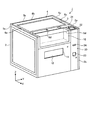
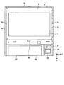
図1に示すように、本発明の一実施形態である自動販売機1は、人が上面2aを見下ろせる程度の高さ寸法を有する直方体状の販売機本体2を備える。販売機本体2の上面2aには、長方形状の表示装置3と、表示装置3上又はその周縁に設けられたタッチパネル部4とが設けられている。表示装置3は、表示画面に各種情報を表示するものである。タッチパネル部4は、人による操作入力を受け付けるものである。タッチパネル部4を表示装置3上又はその周縁に配置することによって、人は4方向から操作することができる。上面2aを形成する4辺5a〜5dの近傍にはそれぞれ、4辺5a〜5dへの人の接近を検出するためのセンサ6a〜6dが設けられている。センサ6a〜6dは、人の接近が検出された場合、検出信号を後述する入出力制御装置に入力する。
As shown in FIG. 1, a
販売機本体2の接客面2bには、販売商品が陳列される陳列部10と、購入した販売商品を取り出すための取出口11が設けられている。取出口11には、奥側に押し込んで開放可能なフラップドア12が取り付けられている。販売商品を購入した購入者は、フラップドア12を開放することによって、取出口11から販売商品を取り出すことができる。
The
販売機本体2は、販売機本体2に対しX方向にスライド可能に構成された金銭回収部20を備える。金銭回収部20の上面には、硬貨投入口21や表示部22等が設けられている。硬貨投入口21は、硬貨を投入する部分であり、金銭回収部20内の図示しないコインメカニズムに連通している。
The
図示しないコインメカニズムは、投入された硬貨の真偽と金種とを識別し、金種毎に硬貨を収容するものである。コインメカニズムによって識別できなかった硬貨は、金銭回収部20の前面に設けられた返却口23から返却される。表示部22は、投入された金額等の各種情報を出力する。
A coin mechanism (not shown) discriminates the authenticity and denomination of inserted coins and accommodates coins for each denomination. Coins that could not be identified by the coin mechanism are returned from the
金銭回収部20の前面には、紙幣投入口24が設けられている。紙幣投入口24は、紙幣を投入する部分であり、金銭回収部20内の図示しない紙幣識別装置に連通している。図示しない紙幣識別装置は、投入された紙幣の真偽と金種を識別して収容するものである。紙幣識別装置によって識別できなかった紙幣は、紙幣投入口24から返却される。
A
〔自動販売機の制御系の構成〕
次に、図3を参照して、自動販売機1の制御系の構成について説明する。
[Vending machine control system configuration]
Next, the configuration of the control system of the
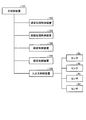
図3は、本発明の一実施形態である自動販売機の制御系の構成を示すブロック図である。図3に示すように、自動販売機1の制御系は、主制御装置101,硬貨処理制御装置102,紙幣処理制御装置103,接客制御装置104,販売制御装置105,及び入出力制御装置106を備える。主制御装置101は、自動販売機1の制御を統括するものであり、マイクロコンピュータ等の情報処理装置によって構成されている。硬貨処理制御装置102,紙幣処理制御装置103,接客制御装置104,販売制御装置105,及び入出力制御装置106は、主制御装置101に対する複数の従制御部に相当し、マイクロコンピュータ等の情報処理装置によって構成されている。
FIG. 3 is a block diagram showing the configuration of the control system of the vending machine according to one embodiment of the present invention. As shown in FIG. 3, the control system of the
硬貨処理制御装置102は、図示しないコインメカニズムを制御することによって、投入硬貨の金種,真偽等の判別、金種別枚数の計算,金庫への余剰硬貨の収容,釣り銭の払い出し等を行わせるものである。紙幣処理制御装置103は、図示しない紙幣識別装置を制御することによって、挿入紙幣の金種,真偽等の判定、金種別枚数の計算、釣り銭の払い出し等を行わせるものである。接客制御装置104は、主制御装置101からの接客指示に従って、販売中ランプ,販売中止ランプ,釣り銭切れランプ等を点灯させたり、図示しない複数の販売商品選択ボタンのいずれかが押下されたのかを検出し、検出信号を主制御装置101に送信したりする。入出力制御装置106は、センサ6a〜6dに接続され、後述するように、センサ6a〜6dから入力された検出信号に従って、表示装置3に表示される情報を制御する。
The coin processing control device 102 controls a coin mechanism (not shown) to determine the denomination and authenticity of inserted coins, calculate the number of denominations, store surplus coins in a safe, pay out change, etc. Is. The banknote
〔表示制御処理〕
このような構成を有する自動販売機1では、入出力制御装置106が、以下に示すように動作することによって、視認位置に関係なく表示装置3の表示画面に表示されている情報を容易に視認可能にする。以下、図4,図5を参照して、本発明の第1及び第2の実施形態である表示制御処理について説明する。
[Display control processing]
In the
〔第1の実施形態〕
始めに、図4を参照して、本発明の第1の実施形態である表示制御処理について説明する。
[First Embodiment]
First, a display control process according to the first embodiment of the present invention will be described with reference to FIG.
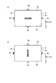
図4は、本発明の第1の実施形態である表示制御処理を説明するための模式図である。本発明の第1の実施形態である表示制御処理では、図4(a)に示すように、自動販売機1の接客面2a側の辺3d方向を下方向の表示向きとして画像情報を表示している通常状態において、センサ6aが人の接近を検出した場合、入出力制御装置106が、図4(b)に示すように、センサ6aが設けられている辺3a側が下方向の表示向きとなるように画像情報の表示向きを変更する。同様に、センサ6b〜6dが人の接近を検出した場合には、入出力制御装置106は、センサ6b〜6dが設けられている辺3b〜3d側が下方向の表示向きとなるように画像情報の表示向きを変更する。このような表示制御処理によれば、自動販売機1に対する人の位置に応じて表示画面に表示する画像情報の向きが変更されるので、人は視認位置に関係なく表示画面に表示されている情報を容易に視認することができる。
FIG. 4 is a schematic diagram for explaining a display control process according to the first embodiment of the present invention. In the display control process according to the first embodiment of the present invention, as shown in FIG. 4A, image information is displayed with the
〔第2の実施形態〕
次に、図5を参照して、本発明の第2の実施形態である表示制御処理について説明する。
[Second Embodiment]
Next, a display control process according to the second embodiment of the present invention will be described with reference to FIG.
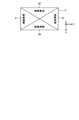
図5は、本発明の第2の実施形態である表示制御処理を説明するための模式図である。本発明の第2の実施形態である表示制御処理では、自動販売機1の接客面2a側の辺3d側を下方向の表示向きとして画像情報を表示している通常状態において、センサ6a〜6dのうちのいずれかが人の接近を検出した場合、入出力制御装置106が、図5に示すように、表示装置4の表示画面をそれぞれ4つの辺3a〜3d側を下方向の表示向きとする4つの分割画面31〜34に分割する。このような表示制御処理によれば、分割画面31〜34のうちのいずれかに表示されている画像情報は人に正対している状態になるので、人は視認位置に関係なく表示画面に表示されている情報を容易に視認することができる。
FIG. 5 is a schematic diagram for explaining a display control process according to the second embodiment of the present invention. In the display control process according to the second embodiment of the present invention, in the normal state in which image information is displayed with the
以上、本発明を適用した実施の形態について説明したが、本実施形態による本発明の開示の一部をなす記述及び図面により本発明は限定されることはない。すなわち、本実施形態に基づいて当業者等によりなされる他の実施の形態、実施例及び運用技術等は全て本発明の範疇に含まれる。 The embodiment to which the present invention is applied has been described above, but the present invention is not limited by the description and the drawings that form part of the disclosure of the present invention according to the present embodiment. That is, other embodiments, examples, operational techniques, and the like made by those skilled in the art based on the present embodiment are all included in the scope of the present invention.
1 自動販売機
2 販売機本体
2a 上面
2b 接客面
3 表示装置
4 タッチパネル部
6a〜6d センサ
20 金銭回収部
21 硬貨投入口
22 表示部
23 返却口
24 紙幣投入口
31〜34 分割画面
101 主制御装置
102 硬貨処理制御装置
103 紙幣処理制御装置
104 接客制御装置
105 販売制御装置
106 入出力制御装置
DESCRIPTION OF
Claims (3)
前記自動販売機本体の上面に設けられ、表示画面に情報を表示する表示装置と、
前記自動販売機本体の側面に対する人の接近を検出する複数の検出手段と、
人の接近を検出した検出手段が配置されている側面側が下方向の表示向きになるように前記表示画面に表示する情報の向きを制御する制御手段と、
を備えることを特徴とする自動販売機。 The vending machine body,
A display device provided on the upper surface of the vending machine main body and displaying information on a display screen;
A plurality of detection means for detecting the approach of a person to the side surface of the vending machine body;
Control means for controlling the direction of information displayed on the display screen so that the side surface on which the detection means that detects the approach of a person is arranged is in a downward display direction;
Vending machine characterized by comprising.
前記自動販売機本体の上面に設けられ、表示画面に情報を表示する表示装置と、
前記自動販売機本体の側面に対する人の接近を検出する複数の検出手段と、
前記複数の検出手段のうちのいずれかによって人の接近が検出された場合、前記表示画面をそれぞれの側面側を下方向の表示向きとする複数の表示画面に分割する制御手段と、
を備えることを特徴とする自動販売機。 The vending machine body,
A display device provided on the upper surface of the vending machine main body and displaying information on a display screen;
A plurality of detection means for detecting the approach of a person to the side surface of the vending machine body;
A control unit that divides the display screen into a plurality of display screens each having a lateral display direction when the approach of a person is detected by any of the plurality of detection units;
Vending machine characterized by comprising.
Priority Applications (1)
| Application Number | Priority Date | Filing Date | Title |
|---|---|---|---|
| JP2010166948A JP2012027770A (en) | 2010-07-26 | 2010-07-26 | Automatic vending machine |
Applications Claiming Priority (1)
| Application Number | Priority Date | Filing Date | Title |
|---|---|---|---|
| JP2010166948A JP2012027770A (en) | 2010-07-26 | 2010-07-26 | Automatic vending machine |
Publications (1)
| Publication Number | Publication Date |
|---|---|
| JP2012027770A true JP2012027770A (en) | 2012-02-09 |
Family
ID=45780608
Family Applications (1)
| Application Number | Title | Priority Date | Filing Date |
|---|---|---|---|
| JP2010166948A Pending JP2012027770A (en) | 2010-07-26 | 2010-07-26 | Automatic vending machine |
Country Status (1)
| Country | Link |
|---|---|
| JP (1) | JP2012027770A (en) |
Cited By (1)
| Publication number | Priority date | Publication date | Assignee | Title |
|---|---|---|---|---|
| CN110322618A (en) * | 2018-03-29 | 2019-10-11 | 富士电机株式会社 | Automatic vending machine |
-
2010
- 2010-07-26 JP JP2010166948A patent/JP2012027770A/en active Pending
Cited By (1)
| Publication number | Priority date | Publication date | Assignee | Title |
|---|---|---|---|---|
| CN110322618A (en) * | 2018-03-29 | 2019-10-11 | 富士电机株式会社 | Automatic vending machine |
Similar Documents
| Publication | Publication Date | Title |
|---|---|---|
| US8714448B2 (en) | Device for handling banknotes comprising a height adjustable user interface | |
| US20150102047A1 (en) | Vending apparatus and product vending method | |
| CN100587736C (en) | Commodity selection device for vending machines | |
| JP2012027770A (en) | Automatic vending machine | |
| JP2016085596A (en) | Money handling device, money handling system, and handling method | |
| JP5860847B2 (en) | Money storage device and self-checkout device | |
| JP2015228100A (en) | Money handling apparatus, money handling system, and banknote display method | |
| JP2015088035A (en) | Coin insertion port and self-checkout device | |
| CN105164735B (en) | Entertainment machines and monitoring systems | |
| JP5599272B2 (en) | Money handling equipment | |
| CN102113029B (en) | Automatic transaction device | |
| US8544728B2 (en) | Money handling apparatus and money handling method | |
| JP4844638B2 (en) | Automatic transaction equipment | |
| JP2013012135A (en) | Bill processing device | |
| JP6198336B2 (en) | Cash processing system | |
| KR101448371B1 (en) | Financial apparatus | |
| JP5786380B2 (en) | vending machine | |
| JP2012198761A (en) | Control panel for money handling device | |
| ES1073686Y (en) | ELECTRONIC MACHINE REGISTER AND CHANGE | |
| JP1780242S (en) | Coin and bill deposit and withdrawal machine | |
| JP2012027772A (en) | Vending machine | |
| JP1788135S (en) | Coin and bill deposit and withdrawal machine | |
| JP1775920S (en) | Coin and bill deposit and withdrawal machine | |
| CN202058230U (en) | Highly reliable paper money counting and counterfeit-discriminating system | |
| JP2017219888A (en) | Money processing system |
Legal Events
| Date | Code | Title | Description |
|---|---|---|---|
| A711 | Notification of change in applicant |
Free format text: JAPANESE INTERMEDIATE CODE: A712 Effective date: 20121025 |