JP2012024967A - One hand braille typewriter - Google Patents
One hand braille typewriter Download PDFInfo
- Publication number
- JP2012024967A JP2012024967A JP2010163793A JP2010163793A JP2012024967A JP 2012024967 A JP2012024967 A JP 2012024967A JP 2010163793 A JP2010163793 A JP 2010163793A JP 2010163793 A JP2010163793 A JP 2010163793A JP 2012024967 A JP2012024967 A JP 2012024967A
- Authority
- JP
- Japan
- Prior art keywords
- braille
- lever
- upper wall
- printing
- Prior art date
- Legal status (The legal status is an assumption and is not a legal conclusion. Google has not performed a legal analysis and makes no representation as to the accuracy of the status listed.)
- Pending
Links
- 230000000994 depressogenic effect Effects 0.000 abstract 1
- 239000011435 rock Substances 0.000 abstract 1
- 230000001154 acute effect Effects 0.000 description 11
- 210000003811 finger Anatomy 0.000 description 11
- 230000002093 peripheral effect Effects 0.000 description 8
- 210000000078 claw Anatomy 0.000 description 7
- 210000003813 thumb Anatomy 0.000 description 5
- NJPPVKZQTLUDBO-UHFFFAOYSA-N novaluron Chemical compound C1=C(Cl)C(OC(F)(F)C(OC(F)(F)F)F)=CC=C1NC(=O)NC(=O)C1=C(F)C=CC=C1F NJPPVKZQTLUDBO-UHFFFAOYSA-N 0.000 description 4
- XEEYBQQBJWHFJM-UHFFFAOYSA-N Iron Chemical compound [Fe] XEEYBQQBJWHFJM-UHFFFAOYSA-N 0.000 description 2
- 208000010415 Low Vision Diseases 0.000 description 2
- 238000010586 diagram Methods 0.000 description 2
- 230000001771 impaired effect Effects 0.000 description 2
- 230000004303 low vision Effects 0.000 description 2
- 239000004925 Acrylic resin Substances 0.000 description 1
- 229920000178 Acrylic resin Polymers 0.000 description 1
- 201000009487 Amblyopia Diseases 0.000 description 1
- 201000004569 Blindness Diseases 0.000 description 1
- 238000006424 Flood reaction Methods 0.000 description 1
- 230000004323 axial length Effects 0.000 description 1
- 230000007423 decrease Effects 0.000 description 1
- 230000003111 delayed effect Effects 0.000 description 1
- 230000004438 eyesight Effects 0.000 description 1
- 238000012840 feeding operation Methods 0.000 description 1
- 229910052742 iron Inorganic materials 0.000 description 1
- 239000002184 metal Substances 0.000 description 1
- 229910052751 metal Inorganic materials 0.000 description 1
- 238000000034 method Methods 0.000 description 1
- 238000012986 modification Methods 0.000 description 1
- 230000004048 modification Effects 0.000 description 1
- 230000000149 penetrating effect Effects 0.000 description 1
- 208000029257 vision disease Diseases 0.000 description 1
- 230000000007 visual effect Effects 0.000 description 1
- 230000004393 visual impairment Effects 0.000 description 1
- 210000000707 wrist Anatomy 0.000 description 1
Images
Landscapes
- Printers Characterized By Their Purpose (AREA)
Abstract
Description
本発明は、点字タイプライターに係り、特に片手で点字入力可能な片手点字タープライターに関する。 The present invention relates to a braille typewriter, and more particularly, to a one-handed braille turner capable of inputting braille with one hand.
近年、各地で地震災害や水害が起きているが、このような被災地において被災する強度弱視障害者や全盲視障害者等の視覚障害被災者も、当然のことながら、救済の対象となり、守られねばならない。 In recent years, earthquake disasters and floods have occurred in various places. Naturally, visually impaired people such as those with severe amblyopia and those with total blindness who are affected in such disaster areas are also subject to relief and are protected. It must be done.
しかしながら、これらの視覚障害被災者たる災害弱者は、後回しにされているのが現状である。従って、これを是正するにあたり、被災地の避難所において、視覚障害被災者を保護するための点字による情報伝達が必須である。このことは、避難所においても、点字タイプライターが必須であることを意味する。 However, the current situation is that these vulnerable people who are suffering from visual impairments are left behind. Therefore, in order to correct this, it is essential to transmit information in Braille to protect the visually impaired at the evacuation shelter in the disaster area. This means that braille typewriters are essential even at shelters.
しかしながら、点字タイプライターとしては、上記特許文献1に記載の指点字装置のような練習機器とか特許文献2に記載の電子点字装置のように操作の複雑なものしか存在しない。
However, there are only Braille typewriters such as practice devices such as the finger Braille device described in the above-mentioned
そこで、本発明は、以上のようなことに対処するため、点字が6つの点字構成要素からなる点字構成体で特定されることを活用して、6つの点字構成要素の配列に対応するキー配列のもとに、片手で簡単に操作可能な片手点字タイプライターを提供することを目的とする。 Therefore, in order to cope with the above, the present invention utilizes the fact that Braille is specified by a Braille component composed of six Braille components, and a key array corresponding to an array of six Braille components. It is an object of the present invention to provide a one-handed Braille typewriter that can be easily operated with one hand.
上記課題の解決にあたり、本発明に係る片手点字タイプライターは、請求項1の記載によれば、
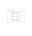
第1〜第3の点字構成要素(Fa、Ma、Ra)及び当該第1〜第3の点字構成要素にそれぞれ対応する第4〜第6の点字構成要素(Fb、Mb、Rb)でもって左右2列に配列してなる点字構成体(L)を用いて、操作者により、その片手の指の操作でもって、点字をテープ(70)に順次印字可能とするようにした片手点字タイプライターであって、
ハウジング(10)と、点字印字機構(T)と、送り機構(S)とを備えて、
ハウジングは、その上壁(10b)の前寄り部位にて、印字用開口部(15)を形成するとともに、上記上壁の後寄り部位にて、上記点字構成体の上記第1〜第6の点字構成要素にそれぞれ対応して位置するように第1〜第6の貫通孔部(12a、12b、13a、13b、14a、14b)を形成してなり、
点字印字機構は、
第1〜第6の印字レバー部材(20a、20b、30a、30b、40a、40b)と、第1〜第6のバネ部材(23、26、33、36、43、46)とを具備して、
第1〜第6の印字レバー部材は、
ハウジング内にてその前後方向に沿い下に凸な形状にて長手状に延在するように収容されるレバーであってその長手方向中間部位にて、上下方向に揺動可能にハウジング内に支持されるレバー(21、31、41、24、34、44)と、押動式入力キー(22、32、42、25、35、45)とをそれぞれ有し、
各レバーの前部(21c、31c、41c、24c、34c、44c)を、上記点字構成体の上記第1〜第6の点字構成要素の各位置に対応する位置にて上記上壁の上記印字用開口部をその下方から臨ませ、かつ、各レバーの後部(21b、31b、41b、24b、34b、44b)を、それぞれ、上記上壁の上記第1〜第6の貫通孔部を通り上下動可能に延出させ、
各対応の入力キーを、それぞれ、各対応のレバーの後部の延出端部に支持し、
第1〜第6のバネ部材を、それぞれ、各対応の入力キーを上記上壁とは反対方向に付勢するように設けて、
操作者が、その片手の指にて、第1〜第6のバネ部材に選択的に抗して第1〜第6の入力キーを選択的に押動操作したとき、各対応のレバーが選択的に揺動してその前部にて印字可能に上記印字用開口部内に進入するようになっており、
送り機構は、
上記上壁の前記前寄り部位の上記印字用開口部に左右方向に隣接して形成される送り用開口部(16)をその直下から臨むようにハウジング内にその前後方向に沿う回転軸(60a)を軸として回転可能に支持されるローラ(60)と、
このローラの近傍にて上記上壁に形成した貫通孔部(17)を通り上下動可能に延出する送り軸(90a)の延出端部に支持される押動式送りキー(90)と、
当該送りキーを前記上壁とは反対方向方へ付勢するバネ部材(92)と、
このバネ部材に抗して送りキーを押動するごとにロータを回転させるように、上記送り軸とローラとの間に連結されるラチェット機構(80)とを備えて、
テープを押さえ板(70a)により押さえるようにして上記上壁の上記前寄り部位上に前記送り用開口部及び前記印字用開口部を覆うように載置した状態にて、前記各レバーの選択的な揺動によるその前部の上記印字用開口部内への進入の際に、当該前部にてテープに点字を印字し、その後上記送りキーの押動操作に伴うローラによりその回転でもって押さえ板による押さえのもとに上記送り用開口部を介してテープを送るようにした。
In solving the above-mentioned problems, the one-hand Braille typewriter according to the present invention, according to the description of
Left and right with first to third braille components (Fa, Ma, Ra) and fourth to sixth braille components (Fb, Mb, Rb) respectively corresponding to the first to third braille components A one-hand Braille typewriter that uses braille structures (L) arranged in two rows, and allows an operator to operate the finger of one hand to sequentially print braille on the tape (70). There,
A housing (10), a Braille printing mechanism (T), and a feed mechanism (S);
The housing forms a printing opening (15) at the front portion of the upper wall (10b), and the first to sixth of the Braille structure at the rear portion of the upper wall. First to sixth through-hole portions (12a, 12b, 13a, 13b, 14a, 14b) are formed so as to correspond to the braille components,
Braille printing mechanism
First to sixth print lever members (20a, 20b, 30a, 30b, 40a, 40b) and first to sixth spring members (23, 26, 33, 36, 43, 46) are provided. ,
The first to sixth print lever members are
A lever that is housed in the housing so as to extend in a longitudinally convex shape along its front-rear direction, and is supported in the housing so that it can swing in the vertical direction at an intermediate portion in the longitudinal direction. Levers (21, 31, 41, 24, 34, 44) and push-type input keys (22, 32, 42, 25, 35, 45), respectively,
The front wall (21c, 31c, 41c, 24c, 34c, 44c) of each lever is printed on the upper wall at a position corresponding to each position of the first to sixth braille components of the braille component. And the rear part (21b, 31b, 41b, 24b, 34b, 44b) of each lever passes through the first to sixth through-hole parts of the upper wall and moves up and down. Extend movably,
Each corresponding input key is supported on the extended end of the rear of each corresponding lever,
The first to sixth spring members are respectively provided so as to urge the corresponding input keys in the direction opposite to the upper wall,
When the operator selectively pushes the first to sixth input keys against the first to sixth spring members with the finger of one hand, the corresponding lever is selected. Oscillates so as to enter the printing opening so that printing is possible at the front part thereof,
The feed mechanism
A rotation shaft (60a) along the front-rear direction in the housing so that the feed opening (16) formed adjacent to the printing opening at the front portion of the upper wall in the left-right direction faces directly below it. ) As a shaft, and a roller (60) supported rotatably.
A push-type feed key (90) supported by an extension end of a feed shaft (90a) extending in the vicinity of this roller so as to be movable up and down through a through hole (17) formed in the upper wall; ,
A spring member (92) for urging the feed key in the direction opposite to the upper wall;
A ratchet mechanism (80) connected between the feed shaft and the roller so as to rotate the rotor each time the feed key is pushed against the spring member;
In a state where the tape is pressed by the pressing plate (70a) and placed on the front side portion of the upper wall so as to cover the feeding opening and the printing opening, the respective levers are selectively operated. When the front part enters into the printing opening by a rocking motion, Braille is printed on the tape at the front part, and then the presser plate is rotated by the roller accompanying the pushing operation of the feed key. The tape was fed through the above-mentioned feeding opening under the pressure of the.
これによれば、当該片手点字タイプライターを用いて点字を印字するにあたっては、操作者が、その片手の指(例えば、人差し指及び中指)でもって、6つの入力キーを選択的に押動操作すれば、対応の印字レバー部材の揺動に基づきテープに点字を印字することができる。 According to this, when printing Braille using the one-hand Braille typewriter, the operator can selectively push the six input keys with the finger of one hand (for example, the index finger and the middle finger). For example, Braille can be printed on the tape based on the swing of the corresponding print lever member.
ここで、各印字レバー部材の入力キー及び印字部が、上述のごとく、点字構成体の点字構成体における6つの点字構成要素の配置に対応している。従って、五十音等の文字とこれに対応する点字の構成の参照のもとに、弱視者に限らず、健常者であって点字に関し何の知識もない者や当該片手点字タイプライターの操作の仕方を知らない初心者であっても、点字構成体の各点字構成要素に対応する入力キーを押動操作するだけで、容易にしかも確実に点字をテープに印字することができる。 Here, as described above, the input key and the printing unit of each print lever member correspond to the arrangement of the six braille components in the braille component of the braille component. Therefore, with reference to the composition of the Japanese syllabary and the corresponding braille structure, not only the low vision person but also a healthy person who has no knowledge of braille or the operation of the one-handed braille typewriter Even a beginner who does not know how to do this can easily and surely print Braille on a tape simply by pressing an input key corresponding to each Braille component of the Braille component.
また、点字の印字後、テープ送るにあたっては、操作者が、片手の親指で送りキーを押動操作すれば、ラチェット機構によるローラの回転のもとに、テープを容易にしかも確実に送ることができる。 In addition, when the tape is fed after Braille printing, if the operator pushes the feed key with the thumb of one hand, the tape can be fed easily and reliably under the rotation of the roller by the ratchet mechanism. it can.
なお、上記各手段の括弧内の符号は、後述する実施形態に記載の具体的手段との対応関係を示す。 In addition, the code | symbol in the bracket | parenthesis of each said means shows the correspondence with the specific means as described in embodiment mentioned later.
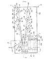
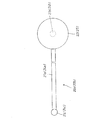
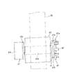
以下、本発明の一実施形態を図面により説明する。図1〜図3は、本発明に係る片手点字タイプライターの一実施形態を示している。この片手点字タイプライターは、直方体形状のハウジング10と、このハウジング10に組み付けてなる点字印字機構T及びテープ送り機構Sとにより構成されている。
Hereinafter, an embodiment of the present invention will be described with reference to the drawings. 1 to 3 show an embodiment of a one-handed Braille typewriter according to the present invention. This one-hand Braille type writer includes a rectangular
ハウジング10は、断面コ字状のハウジング本体10aと、矩形板状の上壁10bとを有している。この上壁10bは、ハウジング本体10aの開口部に着脱可能に装着されて、当該ハウジング本体10aの開口部を閉じている。本実施形態では、上壁10bは、後述する各押しボタン式入力キー及び送りキーと共に、当該片手点字タイプライターのキーボードとしての役割を果たす。なお、図1において、図示左右方向が当該片手点字タイプライターの前後方向に対応する。これに伴い、図示上方及び下方が、それぞれ、当該片手点字タイプライターの右方及び左方に対応する。また、本実施形態では、ハウジング10は、鉄板等の金属板でもって形成されている。
The
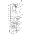
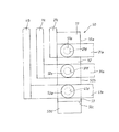
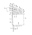
点字印字機構Tは、図1にて示すごとく、6本の印字レバー部材20a、20b、30a、30b、40a及び40bを有している。これら印字レバー部材20a、20b、30a、30b、40a及び40bのうち、2本の印字レバー部材20a、20bは、左右両側の内印字レバー部材20a、20bとして、それぞれ、支持部材50(後述する)にその左右両側から上下方向に傾動可能に支持され、2本の印字レバー部材30a、30bは、左右両側の中印字レバー部材30a、30bとして、それぞれ、支持部材50にその左右両側から上下方向に傾動可能に支持され、また、残りの2本の印字レバー部材40a、40bは、左右両側の外印字レバー部材40a、40bとして、それぞれ、支持部材50にその左右両側から上下方向に傾動可能に支持されている。
As shown in FIG. 1, the Braille printing mechanism T has six
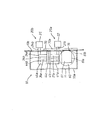
本実施形態において、支持部材50は、図6〜図8のいずれかにて示すごとく、3つのブロック体50a〜50cからなるもので、これらブロック体50a〜50cは、互いに一体的に形成されている。当該ブロック体50a〜50cのうち、ブロック体50cは、台座50d(図2或いは図6参照)を介し、ハウジング本体10aの底壁11の前側部位のうちその中間部位上に設けられている。なお、台座50dは、その下壁にて、ハウジング本体10aの底壁11の前側部位のうちその中間部位上に固着されており、ブロック体50cは、その下壁にて、台座50dの上壁上に固着されている。
In the present embodiment, the
また、ブロック体50bは、その底壁にて、ブロック体50cの上壁上に積層されるように当該ブロック体50cと一体に形成されており、ブロック体50aは、その底壁にて、ブロック体50bの上壁上に積層されるように当該ブロック体50bと一体に形成されている(図7参照)。
Further, the
ブロック体50aは、図7にて示すごとく縦断面(ブロック体50aの前後方向に沿う断面)長方形状となるように、かつ、図8(a)にて示すごとく横断面(ブロック体50aの台座50dの上面に沿う前後方向断面)台形状となるように形成されている。ここで、ブロック体50aの左右方向幅は、図8(a)にて示すごとく、当該ブロック体50aの後壁から前壁にかけて順次狭くなっている。
The
これに伴い、当該ブロック体50aの左右両壁51は、当該ブロック体50aの後壁から前壁にかけて互いに接近するように傾斜しており、これら左右両壁51の各傾斜角度は、それぞれ、ブロック体50aの前後方向中心面に対し所定の鋭角α°となっている。この所定の鋭角α°は、後述のごとく、ブロック体50aに揺動可能に支持した左右両側の内印字レバー部材20a、20bの各印字部を、点字構成体L(図12参照)の6つの点字構成要素の両前側点字構成要素Fa、Fbに対応させるように設定されている。なお、点字構成体Lは、図12にて示すごとく、両前側点字構成要素Fa、Fb、両中側点字構成要素Ma、Mb及び両後側点字構成要素Ra、Rbでもって、6つの点字構成要素の配置構成となるように定められている。また、点字構成体Lは、図12にて示すごとく、前側点字構成要素Fa、中側点字構成要素Ma及び後側点字構成要素Raを左側一列に配置し、これら前側点字構成要素Fa、中側点字構成要素Ma及び後側点字構成要素Raの右側にそれぞれ位置するように前側点字構成要素Fb、中側点字構成要素Mb及び後側点字構成要素Rbを右側一列に配置して構成されている。
Accordingly, the left and
ブロック体50bは、ブロック体50aと同様に、縦断面長方形状となるように、かつ、図8(b)にて示すごとく、横断面(ブロック体50bの台座50dの上面に沿う前後方向断面)台形状となるように形成されている。ここで、ブロック体50bの左右方向幅は、図8(b)にて示すごとく、当該ブロック体50bの後壁から前壁にかけて順次狭くなっている。
Similarly to the
これに伴い、当該ブロック体50bの左右両壁52は、当該ブロック体50bの後壁から前壁にかけて互いに接近するように傾斜しており、これら左右両壁52の各傾斜角度は、それぞれ、ブロック体50bの前後方向中心面に対し所定の鋭角β°となっている。但し、当該所定の鋭角β°は、後述のごとく、ブロック体50bに揺動可能に支持した左右両側の中印字レバー部材30a、30bの各印字部を、点字構成体L(図12参照)の6つの点字構成要素の両中側点字構成要素Ma、Mbに対応させるように、所定の鋭角α°よりも小さく設定されている。従って、ブロック体50bの前壁の左右方向幅は、ブロック体50aの前壁の左右方向幅よりも広くなっている。
Accordingly, the left and
また、ブロック体50cは、ブロック体50aと同様に、縦断面長方形状となるように、かつ、図8(c)にて示すごとく横断面(ブロック体50aの台座50dの上面に沿う前後方向断面)台形状となるように形成されている。ここで、ブロック体50cの左右方向幅は、図8(c)にて示すごとく、当該ブロック体50cの後壁から前壁にかけて順次狭くなっている。
Further, the
これに伴い、当該ブロック体50cの左右両壁53は、当該ブロック体50cの後壁から前壁にかけて互いに接近するように傾斜しており、これら左右両壁53の各傾斜角度は、それぞれ、ブロック体50cの前後方向中心面に対し所定の鋭角γ°となっている。但し、当該所定の鋭角γ°は、後述のごとく、ブロック体50cに揺動可能に支持した左右両側の外印字レバー部材40a、40bの各印字部を、点字構成体L(図12参照)の6つ点字構成要素の両後側点字構成要素Ra、Rbに対応させるように、所定の鋭角β°よりも小さく設定されている。なお、支持部材50において、各ブロック体50a〜50cの前後方向中心面は、ハウジング本体10aの底壁11の同一の前後方向法線面内にある。
Accordingly, the left and
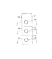
左側内印字レバー部材20aは、図2〜図6のいずれかにて示すごとく、コ字状レバー21と、入力キー22とにより構成されている。コ字状レバー21は、横断面円柱状のロッドからなるもので、このコ字状レバー21は、揺動レバー部21aと、この揺動レバー部21aの後端部から当該揺動レバー部21aに対しL字状に延出する後側レバー部21bと、揺動レバー部21aの前端部から後側レバー部21bに平行となるように延出する前側レバー部21cとにより構成されている。
The left inner
しかして、このように構成した左側内印字レバー部材20aにおいては、揺動レバー部21aが、その長手方向中間部位にて、支持部材50のブロック体50aの左側壁51(図6参照)に、左側ネジ51a(図6参照)により上下方向に揺動可能に支持されている。なお、左側ネジ51aは、揺動レバー部21aの長手方向中間部位に形成した貫通孔部21d(図6参照)に相対回動可能に挿通されて、ブロック体50aの左側壁51に形成した左側ネジ孔部51b(図8(a)参照)に締着されている。
Thus, in the left inner
これに伴い、左側内印字レバー部材20aの後側レバー部21bは、図2にて示すごとく、ハウジング10の上壁10bに形成した前側貫通孔部12aを通して外方へ延出されている。本実施形態では、前側貫通孔部12aは、図1或いは図2にて示すごとく、他の前側貫通孔部12b、両中側貫通孔部13a、13b及び両後側貫通孔部14a及び14bとともに、上壁10bに貫通状に形成されている。ここで、両前側貫通孔部12a、12b、両中側貫通孔部13a、13b及び両後側貫通孔部14a、14bは、それぞれ、点字構成体Lの両前側点字構成要素Fa、Fb、両中側点字構成要素Ma、Mb及び両後側点字構成要素Ra、Rbに対応するように上壁10bに形成されている。
Accordingly, the
また、左側内印字レバー部材20aの前側レバー部21cは、その先端部にて、上壁10bの印字用開口部15(図1及び図2参照)を通して外方を臨むように、揺動レバー部21aの前端部から外方へ延出している。本実施形態において、前側レバー部21cの先端部は、以後、印字部ともいい、後述する前側レバー部24cの先端部、両中側レバー部31c、34cの各先端部及び両後側レバー部41c、44cの各先端部と共に、外方へ凸な半球状となるように形成されている。
Further, the
入力キー22は、コ字状レバー21の後側レバー部21bの延出端部に同軸的に支持されており、この入力キー22の下端部と上壁10bの貫通孔部12aの外周部との間には、コイルスプリング23が、後側レバー部21bに同軸的に挿通されるようにして挟持されている。これにより、コイルスプリング23は、入力キー22を外方(上壁10bの外方)に向けて付勢する。
The
右側内印字レバー部材20bは、左側内印字レバー部材20aと同一の構成を有するように形成されており、当該右側内印字レバー部材20bは、左側内印字レバー部材20aのコ字状レバー21及び入力キー22にそれぞれ対応するコ字状レバー24及び入力キー25を有する。ここで、コ字状レバー24は、コ字状レバー21の揺動レバー部21a、後側レバー部21b及び前側レバー部21cにそれぞれ対応する揺動レバー部24a、後側レバー部24b及び前側レバー部24c(図4参照)を有する。
The right inner
しかして、このように構成した右側内印字レバー部材20bにおいては、揺動レバー部24aが、その長手方向中間部位にて、支持部材50のブロック体50aの右側壁51(図8(a)参照)に、右側ネジ(図示しない)により上下方向に揺動可能に支持されている。なお、当該右側ネジは、揺動レバー部24aの長手方向中間部位に形成した貫通孔部に相対回動可能に挿通されて、ブロック体50aの右側壁51に形成した右側ネジ孔部51bに締着されている。
Thus, in the right inner
これに伴い、右側内印字レバー部材20bの後側レバー部24bは、ハウジング10の上壁10bの前側貫通孔部12bを通して外方へ延出されている。また、右側内印字レバー部材20bの前側レバー部24cは、その先端部にて、上壁10bの印字用開口部15を通して外方を臨むように、揺動レバー部24aの前端部から上方へ延出している。なお、前側レバー部24cの先端部は、以後、印字部ともいう。
Accordingly, the
入力キー25は、コ字状レバー24の後側レバー部24bの延出端部に同軸的に支持されており、この入力キー25の下端部と上壁10bの貫通孔部12bの外周部との間には、コイルスプリング26(図1参照)が、後側レバー部24bに同軸的に挿通されるようにして挟持されている。これにより、コイルスプリング26は、入力キー25を外方に向けて付勢する。
The
左側中印字レバー部材30aは、図2にて示すごとく、コ字状レバー31と、入力キー32とにより構成されている。コ字状レバー31は、横断面円柱状のロッドからなるもので、このコ字状レバー31は、揺動レバー部31aと、この揺動レバー部31aの後端部から当該揺動レバー部31aに対しL字状に延出する後側レバー部31bと、揺動レバー部31aの前端部から後側レバー部31bに平行となるように延出する前側レバー部31cとにより構成されている。
As shown in FIG. 2, the left middle
しかして、このように構成した左側中印字レバー部材30aにおいては、揺動レバー部31aが、その長手方向中間部位にて、支持部材50のブロック体50bの左側壁52に、左側ネジ52aにより上下方向に揺動可能に支持されている。なお、左側ネジ52aは、揺動レバー部31aの長手方向中間部位に形成した貫通孔部31d(図6参照)に相対回動可能に挿通されて、ブロック体50bの左側壁52に形成した左側ネジ孔部52b(図8(b)参照)に締着されている。
Thus, in the left middle
これに伴い、左側中印字レバー部材30aの後側レバー部31bは、図2にて示すごとく、ハウジング10の上壁10bの中側貫通孔部13aを通して外方へ延出されている。
Accordingly, the
また、左側中印字レバー部材30aの前側レバー部31cは、その先端部にて、上壁10bの印字用開口部15を通して外方を臨むように、揺動レバー部31aの前端部から外方へ延出している。なお、前側レバー部31cの先端部は、以後、印字部ともいう。
Also, the
入力キー32は、コ字状レバー31の後側レバー部31bの延出端部に同軸的に支持されており、この入力キー32の下端部と上壁10bの貫通孔部13aの外周部との間には、コイルスプリング33が、後側レバー部31bに同軸的に挿通されるようにして挟持されている。これにより、コイルスプリング33は、入力キー32を外方に向けて付勢する。
The
右側中印字レバー部材30bは、左側中印字レバー部材30aと同一の構成を有するように形成されており、当該右側中印字レバー部材30bは、左側中印字レバー部材30aのコ字状レバー31及び入力キー32にそれぞれ対応するコ字状レバー34及び入力キー35を有する。ここで、コ字状レバー34は、コ字状レバー31の揺動レバー部31a、後側レバー部31b及び前側レバー部31cにそれぞれ対応する揺動レバー部34a、後側レバー部34b及び前側レバー部34cを有する。
The right middle print lever member 30b is formed to have the same configuration as the left middle
しかして、このように構成した右側中印字レバー部材30bにおいては、揺動レバー部34aが、その長手方向中間部位にて、支持部材50のブロック体50bの右側壁52に、右側ネジ(図示しない)により上下方向に揺動可能に支持されている。なお、当該右側ネジは、揺動レバー部34aの長手方向中間部位に形成した貫通孔部に相対回動可能に挿通されて、ブロック体50bの右側壁52に形成した右側ネジ孔部52bに締着されている。
Thus, in the right middle print lever member 30b configured as described above, the swing lever portion 34a has a right screw (not shown) attached to the
これに伴い、右側中印字レバー部材30bの後側レバー部34bは、ハウジング10の上壁10bの前側貫通孔部13bを通して外方へ延出されている。また、右側中印字レバー部材30bの前側レバー部34cは、その先端部にて、上壁10bの印字用開口部15を通して外方を臨むように、揺動レバー部34aの前端部から外方へ延出している。なお、前側レバー部34cの先端部は、以後、印字部ともいう。
Accordingly, the
入力キー35は、コ字状レバー34の後側レバー部34bの延出端部に同軸的に支持されており、この入力キー35の下端部と上壁10bの貫通孔部13bの外周部との間には、コイルスプリング36(図1参照)が、後側レバー部34bに同軸的に挿通されるようにして挟持されている。これにより、コイルスプリング36は、入力キー35を外方に向けて付勢する。
The
左側外印字レバー部材40aは、図2にて示すごとく、コ字状レバー41と、入力キー42とにより構成されている。コ字状レバー41は、横断面円柱状のロッドからなるもので、このコ字状レバー41は、揺動レバー部41aと、この揺動レバー部41aの後端部から当該揺動レバー部41aに対しL字状に延出する後側レバー部41bと、揺動レバー部41aの前端部から後側レバー部41bに平行となるように延出する前側レバー部41cとにより構成されている。
The left outer
しかして、このように構成した左側外印字レバー部材40aにおいては、揺動レバー部41aが、その長手方向中間部位にて、支持部材50のブロック体50cの左側壁53に、左側ネジ53aにより上下方向に揺動可能に支持されている。なお、左側ネジ53aは、揺動レバー部41aの長手方向中間部位に形成した貫通孔部41b(図6参照)に相対回動可能に挿通されて、ブロック体50cの左側壁53に形成した左側ネジ孔部53b(図8(c)参照)に締着されている。
Thus, in the left outer
これに伴い、左側外印字レバー部材40aの後側レバー部41bは、図2にて示すごとく、ハウジング10の上壁10bの後側貫通孔部14aを通して外方へ延出されている。
Accordingly, the rear lever portion 41b of the left outer
また、左側外印字レバー部材40aの前側レバー部41cは、その先端部にて、上壁10bの印字用開口部15を通して外方を臨むように、揺動レバー部41aの前端部から外方へ延出している。なお、前側レバー部41cの先端部は、以後、印字部ともいう。
Further, the
入力キー42は、コ字状レバー41の後側レバー部41bの延出端部に同軸的に支持されており、この入力キー42の下端部と上壁10bの貫通孔部14aの外周部との間には、コイルスプリング43が、後側レバー部41bに同軸的に挿通されるようにして挟持されている。これにより、コイルスプリング43は、入力キー42を外方に向けて付勢する。
The
右側外印字レバー部材40bは、左側外印字レバー部材40aと同一の構成を有するように形成されており、当該右側外印字レバー部材40bは、左側外印字レバー部材40aのコ字状レバー41及び入力キー42にそれぞれ対応するコ字状レバー44及び入力キー45を有する。ここで、コ字状レバー44は、コ字状レバー41の揺動レバー部41a、後側レバー部41b及び前側レバー部41cにそれぞれ対応する揺動レバー部44a、後側レバー部44b及び前側レバー部44cを有する。
The right outer print lever member 40b is formed to have the same configuration as the left outer
しかして、このように構成した右側外印字レバー部材40bにおいては、揺動レバー部44aが、その長手方向中間部位にて、支持部材50のブロック体50cの右側壁53に、右側ネジ(図示しない)により上下方向に揺動可能に支持されている。なお、当該右側ネジは、揺動レバー部44aの長手方向中間部位に形成した貫通孔部に相対回動可能に挿通されて、ブロック体50cの右側壁53に形成した右側ネジ孔部53bに締着されている。
Thus, in the right outer print lever member 40b configured as described above, the
これに伴い、右側外印字レバー部材40bの後側レバー部44bは、ハウジング10の上壁10bの後側貫通孔部14bを通して外方へ延出されている。また、右側外印字レバー部材40bの前側レバー部44cは、その先端部にて、上壁10bの印字用開口部15を通して外方を臨むように、揺動レバー部44aの前端部から外方へ延出している。なお、前側レバー部44cの先端部は、以後、印字部ともいう。
Accordingly, the rear lever portion 44b of the right outer print lever member 40b is extended outward through the rear through hole portion 14b of the
入力キー45は、コ字状レバー44の後側レバー部44bの延出端部に同軸的に支持されており、この入力キー45の下端部と上壁10bの貫通孔部14bの外周部との間には、コイルスプリング46(図1参照)が、後側レバー部44bに同軸的に挿通されるようにして挟持されている。これにより、コイルスプリング46は、入力キー45を外方に向けて付勢する。
The
以上のように構成した点字印字機構Tにおいては、所定の鋭角α°、所定の鋭角β°及び所定の鋭角γ°が、上述のように設定されていることから、左右両側の内印字レバー部材20a、20bの各印字部(各前側レバー部21c、24cの先端部)、左右両側の中印字レバー部材30a、30bの各印字部(各前側レバー部31c、34cの先端部)及び左右両側の外印字レバー部材40a、40bの各印部(各前側レバー部41c、44cの先端部)が、それぞれ、点字構成体Lの両前側点字構成要素Fa、Fb、両中側点字構成要素Ma、Mb及び両後側点字構成要素Ra、Rbに対する上壁10bの印字用開口部15内の各対応位置に位置する。このことは、各入力キー22、25、32、35、42及び45が、それぞれ、各点字構成要素Fa、Fb、Ma、Mb、Ra及びRbに対応することを意味する。また、図13にて示す点字表において、各点字を構成する6つの点において、図示左下側、左中側及び左上側の各点が、それぞれ、図12の各点字構成要素Fb、Mb及びRbに対応し、また、図13にて図示右下側、右中側及び右上側の各点が、それぞれ、図12の各点字構成要素Fa、Ma及びRaに対応する。
In the Braille printing mechanism T configured as described above, the predetermined acute angle α °, the predetermined acute angle β °, and the predetermined acute angle γ ° are set as described above. 20a and 20b (the front end portions of the
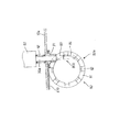
テープ送り機構Sは、図1、図2、図3、図9或いは図10にて示すごとく、円柱状ローラ60及び前後両側L字状支持壁61を有しており、ローラ60は、ハウジング10の前左側隅角部内に収容されている。当該ローラ60は、次のように、ハウジング10内の上壁10bの前左側隅角部に前後両側L字状支持壁61により回転可能に支持されている。
As shown in FIG. 1, FIG. 2, FIG. 3, FIG. 9 or FIG. 10, the tape feeding mechanism S has a
ここで、前後両側L字状支持壁61は、それぞれ、支持壁部61aから装着壁部61bをL字状に延出してなるもので、当該前後両側L字状支持壁61は、各支持壁部61aにてローラ60の回転軸をその前後両端部側から回転自在に支持するようにして、各装着壁部61bにて、上壁10bの前左側隅角部に装着されている。これより、ローラ60は、その回転軸60aにて、ハウジング10の前後方向に沿うように前後両側L字状支持壁61により回転自在に支持されている。
Here, the front and rear side L-shaped
また、ローラ60は、その上端部にて、上壁10bの前左側隅角部に形成した送り用開口部16(図1〜図3のいずれか参照)内に突出しており、このローラ60は、その回転により、その上端部にて、送り用開口部16を介し、点字印字用テープ70にその下面側から押圧的に接触して、当該点字印字用テープ70を左右方向に送る役割を果たす。本実施形態において、点字印字用テープ70は、図1にて示すごとく、ハウジング10の上壁10bの前側中間部位上に左右方向に沿い載置されて、透明のアクリル樹脂からなる押さえ板70aにより上方から上壁10bの前側中間部位上に押し付けられている。なお、押さえ板70aは、図2にて示すごとく、その後端部を基準に傾斜状に持ち上げ可能となっている。
Moreover, the
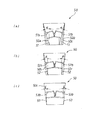
また、テープ送り機構Sは、ラチェット機構80及び送りキー90を有している。ラチェット機構80は、爪車であるラチェット80aと、係止片80bとを有しており、ラチェット80aは、その背板部81にて、ローラ60の回転軸60aの前端部に同軸的に支持されている。ここで、このラチェット80aの一連の爪部82は、背板部81の外周部からその周方向において等角度間隔にて前方に向け延出されている。
The tape feed mechanism S has a
係止片80bは、その上部83にて、環状ボス91(後述する)の中空部内にて、送りキー90を後述のように支持する送り軸90aにネジ止めされており、この係止片80bの下部84は、上部83の下端部から上下方向(送り軸90aの軸方向)に傾動可能に延出されている。但し、係止片80bは、上部83に対し、図10にて図示傾斜位置から下方へのみ傾動するように連結されている。
The
このように構成したラチェット機構80においては、係止片80bが、送り軸90aの下動に伴い、ラチェット80aの一連の爪部82のいずれか1つに上方から係止して、当該爪部82を下方へ押動することで、ラチェット80aを回転させる。また、係止片80bは、送り軸90aの上動に伴い、上述のいずれか1つの爪部82により下方へ傾動されて当該爪部82との係止から解離しつつ上動する。
In the
送り軸90aは、環状ボス91、L字状支持壁61の上壁部61b及び上壁10bの貫通孔部17(図2参照)を通り延出されており、この送り軸90aの延出端部には、送りキー90が同軸的に支持されている。また、コイルスプリング92は、送り軸90aに同軸的に嵌装されて、送りキー90の下部と上壁10bの貫通孔部17の外周部との間に挟持されており、このコイルスプリング92は、送りキー90を上壁10bとは反対方向へ付勢する。本実施形態では、コイルスプリング92が自然長を維持するときにも、送り軸90aは、その下部にて環状ボス91内に維持される軸長を有する。なお、環状ボス91は、上壁10bにL字状支持壁61の上壁部61bを介し組み付けられている。
The
以上のように構成した本実施形態において、当該片手点字タイプライターを用いて点字を印字するにあたっては、次のようにして行う。なお、テープ70が、図1にて示すごとく、当該片手点字タイプライターのハウジング10の上壁10b上にセットされているものとする。なお、テープ70は、押さえ板70aにより、上壁10bの両開口部15、16を上方から覆うように押さえ付けられているものとする。また、現段階では、五十音のうち、「た」及び「ち」が、順次、既に点字(図13参照)として印字されているものとする。
In the present embodiment configured as described above, Braille is printed using the one-hand Braille typewriter as follows. It is assumed that the
このような段階において、五十音のうちの「つ」を点字として印字するにあたっては、まず、操作者は、左手を当該片手点字タイプライターの上壁10b上におく。このとき、左手は、その手首を上壁10bの前側部位上に置き、親指をテープ送り機構Sの送りキー90側に位置させるとともに、残りの指、例えば、人差し指及び中指を、点字印字機構Tの6つの入力キー20a〜40b側に位置させる。このことは、左手の親指でテープ送り機構Tの送り操作をするとともに、人差し指及び中指で6つの入力キー20a〜40bの押動操作をすることを意味する。
In such a stage, when printing "T" of the fifty-sounds as Braille, first, the operator places his left hand on the
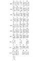
また、上述のごとく、「つ」を点字として印字するにあたり、図13の図表に基づき「つ」に対応する点字を参照して、当該点字が、各点字構成要素Rb、Ra、Ma及びFbでもって特定されることを確認する。 Further, as described above, when printing “tsu” as braille, referring to the braille corresponding to “tsu” based on the chart of FIG. 13, the braille is represented by each braille component Rb, Ra, Ma, and Fb. Confirm that it is specified.
然る後、テープ送り機構Sが、「ち」を点字により印字したままの状態にあれば、操作者は、左手の親指により、テープ送り機構Sの送りキー90を、コイルスプリング92に抗して押動操作する。これに伴い、送り軸90aが、ラチェット機構80の係止片80bと共に下動する。
Thereafter, if the tape feeding mechanism S is still in a state where “C” is printed in Braille, the operator presses the feeding
すると、このような下動過程において、係止片80bが、その下部84にて、ラチェット80aの一爪部82を下方へ押動し、ラチェット80aが当該一爪部82の下方への押動に応じて回転してロータ60を同一方向に回転させる。これに伴い、テープ70が、ロータ60の回転にあわせて上壁10bの左側から右側へ向かう方向へ送られる。これにより、テープ70のうち「つ」に対応する点字を印字する部位が新たに上壁10bの開口部15上に達する。なお、テープ70は、押さえ板70aにより上壁10b上に押さえつけられているので、当該テープ70は、ローラ60により確実に送られ得る。
Then, in such a downward movement process, the
しかして、「つ」に対応する点字を印字するにあたり、まず、各点字構成要素Rb、Ra、Ma及びFbのうち、点字構成要素Rbに対応する右側後印字レバー部材40bの入力キー45をコイルスプリング46に抗して押動操作する。すると、右側後印字レバー部材40bが、その揺動レバー部44aにて、支持部材50のブロック体50cの右側壁53に沿い上記右側ネジ(左側ネジ53aに対応)の軸を中心として図6にて図示時計方向に揺動して、前側レバー部44cの印字部によりテープ70に下方から印字する。このことは、点字構成要素Rbがテープ70に隆起形成されることを意味する。
Therefore, when printing the braille corresponding to “tsu”, first, among the braille components Rb, Ra, Ma, and Fb, the
次に、点字構成要素Raに対応する左側内印字レバー部材40aの入力キー42をコイルスプリング43に抗して押動操作する。すると、左側後印字レバー部材40aが、その揺動レバー部41aにて、支持部材50のブロック体50cの左側壁53に沿い左側ネジ53aの軸を中心として、揺動レバー部44aと同様に揺動して、前側レバー部41cの印字部によりテープ70に下方から印字する。このことは、点字構成要素Raがテープ70に隆起形成されることを意味する。
Next, the
また、点字構成要素Maに対応する左側中印字レバー部材30aの入力キー32をコイルスプリング33に抗して押動操作する。すると、左側中印字レバー部材30aが、その揺動レバー部31aにて、支持部材50のブロック体50bの左側壁52に沿い左側ネジ52aの軸を中心として、図6にて図示時計方向に揺動して、前側レバー部31cの印字部によりテープ70に下方から印字する。このことは、点字構成要素Maがテープ70に隆起形成されることを意味する。
Further, the
さらに、点字構成要素Fbに対応する右側前印字レバー部材20bの入力キー25をコイルスプリング26に抗して押動操作する。すると、右側前印字レバー部材20bが、その揺動レバー部24aにて、支持部材50のブロック体50aの右側壁51に沿い右側ネジ(左側ネジ51aに対応)の軸を中心として、図6にて図示時計方向に揺動して、前側レバー部24cの印字部によりテープ70に下方から印字する。このことは、点字構成要素Fbがテープ70に隆起形成されることを意味する。
Further, the
以上により、「つ」が点字として、テープ70に印字される。また、五十音のうち、「つ」に限ることなく、五十音のうちの他の文字を点字により印字するにあたっても、当該片手点字タイプライターを用いれば、上述と実質的に同様に印字される。
As described above, “T” is printed on the
ここで、点字印字機構Tの各左右両側の前印字レバー部材20a、20b、中印字レバー部材30a、30b及び後印字レバー部材40a、40bが、上述のごとく、それぞれ、支持部材50の各ブロック体50a〜50cに支持されているから、テープ70に対する点字の印字が、各左右両側の前印字レバー部材20a、20b、中印字レバー部材30a、30b及び後印字レバー部材40a、40bの入力キーの押動操作でもって、確実に点字として印字され得る。
Here, as described above, the front
また、各左右両側の前印字レバー部材20a、20b、中印字レバー部材30a、30b及び後印字レバー部材40a、40bの揺動レバー部21a、24a、31a、34a、41a及び44aが、上述のごとく、各ブロック体50a〜50cにより上下方向に揺動可能に支持されている。従って、点字の印字にあたっては、入力キーの押動操作が、当該入力キーに対応する揺動レバー部の揺動を、梃子の原理として利用した状態で、対応の前側レバー部を大きく上動させる。その結果、当該片手点字タイプライターによる点字の印字を楽に行うことができる。
Further, the
また、各左右両側の前印字レバー部材20a、20b、中印字レバー部材30a、30b及び後印字レバー部材40a、40bの入力キー及び印字部が、上述のごとく、点字構成体Lの点字構成体における6つの点字構成要素Fa、Fb、Ma、Mb、Ra、Rbの配置に対応している。
Further, as described above, the input keys and the printing portions of the front
従って、図13にて示す図表の五十音の各文字とこれに対応する点字の構成を参照のもとに、弱視者に限らず、健常者であって点字に関し何の知識もない者や当該片手点字タイプライターの操作の仕方を知らない初心者であっても、点字構成体Lの点字構成体における各点字構成要素に対応する入力キーを押動操作するだけで、容易にしかも確実に点字をテープ70に印字することができる。
Therefore, with reference to the composition of each of the Japanese syllabary characters in the chart shown in FIG. 13 and the braille structure corresponding thereto, not only the low vision person but also a healthy person who has no knowledge of Braille, Even beginners who do not know how to operate the one-handed Braille typewriter can easily and surely braille simply by pressing the input key corresponding to each Braille component in the Braille component of the Braille component L Can be printed on the
特に、当該片手点字タイプライターが、地震災害や水害等の被災地の避難所に保管されていれば、点字に関し何の知識もない者でも、弱視者に急ぎ伝達すべき情報を、当該片手点字タイプライターを用いることにより、容易に点字により印字することができる。その結果、ともすれば救済に遅れをきたす被災弱視者の救済を迅速に行うことができる。なお、テープ70に印字された文字は、弱視者の親指により或いは健常者の目視でもって、容易に確認可能である。
In particular, if the one-handed Braille typewriter is stored at a shelter in a disaster-stricken area such as an earthquake disaster or flood, information that should be urgently communicated to low-sighted people can be sent even to those who have no knowledge of Braille. By using a typewriter, it is possible to easily print in braille. As a result, it is possible to swiftly provide relief for a weakly sighted disaster victim who is delayed in relief. It should be noted that the characters printed on the
また、テープ70の送りは、送り機構Sの送りキー90を押動操作するだけで、ラチェット機構80によるローラ60の回転のもと、容易にしかも確実になされ得る。
Also, the
また、当該片手点字タイプライターが、上述のように構成した点字印字機構T及び送り機構Sを上述のごとく点字の印字可能にハウジング10に組み付けて構成されているので、この片手点字タイプライターは、単なる機械的操作のみで点字を印字することができる。このことは、当該片手点字タイプライターが、電動機等の電気的素子に依存することなく、単なる機械的素子のみによる簡単な構成でもって、簡易なタイプライターとして提供され得ることを意味する。
In addition, the one-hand Braille typewriter is constructed by assembling the Braille printing mechanism T and the feeding mechanism S configured as described above to the
なお、本発明の実施にあたり、上記実施形態に限ることなく、次のような種々の変形例が挙げられる。
(1)本発明の実施にあたり、当該片手点字タイプライターは、左手ではなく、右手で操作し得るように構成することも可能である。
(2)本発明の実施にあたり、五十音に限ることなく、例えば、数字、アルファベットや漢字等も、点字と対象させる図表があれば、上記実施形態と同様に、当該片手点字タイプライターにより点字として印字することができる。
(3)本発明の実施にあたり、上記実施形態にて述べた各印字レバー部材のレバーは、コ字状に限ることなく、下に凸な湾曲形状或いは屈曲形状その他の下に凸な形状であってもよい。
(4)本発明の実施にあたり、上記実施形態にて述べた各印字レバー部材は、支持部材50に限ることなく、ハウジング10の内壁に支持されるようにしてもよい。
(5)本発明の実施にあたり、上記実施形態にて述べた形状に限ることなく、各前側レバー部及び各後側レバー部が、上述のごとく、点字構成体Lの各点字構成要素の配置に対応するように位置すれば、各印字レバー部材は、どのような形状であってもよい。
In carrying out the present invention, the following various modifications are possible without being limited to the above embodiment.
(1) In carrying out the present invention, the one-hand Braille typewriter can be configured to be operated with the right hand instead of the left hand.
(2) In carrying out the present invention, not limited to the Japanese syllabary, for example, if there is a diagram that targets numbers, alphabets, kanji, etc. as braille, as in the above embodiment, the one hand braille typewriter Can be printed as
(3) In practicing the present invention, the lever of each print lever member described in the above embodiment is not limited to a U-shape, and has a downwardly curved shape, a bent shape, or other downwardly convex shape. May be.
(4) In carrying out the present invention, each print lever member described in the above embodiment is not limited to the
(5) In carrying out the present invention, the front lever portion and the rear lever portion are not limited to the shapes described in the above embodiment, and the braille components of the braille component L are arranged as described above. Each print lever member may have any shape as long as it is positioned so as to correspond.
Fa、Fb、Ma、Mb、Ra、Rb…点字構成要素、L…点字構成体、S…送り機構、
T…点字印字機構、10…ハウジング、10b…上壁、
12a、12b、13a、13b、14a、14b、17…貫通孔部、
15…印字用開口部、16…送り用開口部、20a、20b…前印字レバー部材、
30a、30b…中印字レバー部材、40a、40b…後印字レバー部材、
21、31、41、24、34、44…コ字状レバー、
21b、31b、41b、24b、34b、44b…後側レバー部、
21c、31c、41c、24c、34c、44c…前側レバー部、
22、32、42、25、35、45…入力キー、
23、26、33、36、43、46…コイルスプリング、60…ローラ、
60a…回転軸、70…テープ、70a…押さえ板、80…ラチェット機構、
90a…送り軸、90…送りキー。
Fa, Fb, Ma, Mb, Ra, Rb ... Braille components, L ... Braille components, S ... Feed mechanism,
T ... Braille printing mechanism, 10 ... Housing, 10b ... Upper wall,
12a, 12b, 13a, 13b, 14a, 14b, 17 ... through hole,
15 ... Printing opening, 16 ... Feeding opening, 20a, 20b ... Front printing lever member,
30a, 30b ... middle print lever member, 40a, 40b ... rear print lever member,
21, 31, 41, 24, 34, 44 ... U-shaped lever,
21b, 31b, 41b, 24b, 34b, 44b ... rear lever part,
21c, 31c, 41c, 24c, 34c, 44c ... front lever part,
22, 32, 42, 25, 35, 45 ... input keys,
23, 26, 33, 36, 43, 46 ... coil spring, 60 ... roller,
60a ... rotating shaft, 70 ... tape, 70a ... pressing plate, 80 ... ratchet mechanism,
90a ... feed axis, 90 ... feed key.
Claims (1)
ハウジングと、点字印字機構と、送り機構とを備えて、
前記ハウジングは、その上壁の前寄り部位にて、印字用開口部を形成するとともに、前記上壁の後寄り部位にて、前記点字構成体の前記第1〜第6の点字構成要素にそれぞれ対応して位置するように第1〜第6の貫通孔部を形成してなり、
前記点字印字機構は、
第1〜第6の印字レバー部材と、第1〜第6のバネ部材とを具備して、
前記第1〜第6の印字レバー部材は、
前記ハウジング内にてその前後方向に沿い下に凸な形状にて長手状に延在するように収容されるレバーであってその長手方向中間部位にて、上下方向に揺動可能に前記ハウジング内に支持されるレバーと、押動式入力キーとをそれぞれ有し、
前記各レバーの前部を、前記点字構成体の前記第1〜第6の点字構成要素の各位置に対応する位置にて前記上壁の前記印字用開口部をその下方から臨ませ、かつ、前記各レバーの後部を、それぞれ、前記上壁の前記第1〜第6の貫通孔部を通り上下動可能に延出させ、
各対応の前記入力キーを、それぞれ、各対応の前記レバーの後部の延出端部に支持し、
前記第1〜第6のバネ部材を、それぞれ、各対応の前記入力キーを前記上壁とは反対方向に付勢するように設けて、
操作者が、その片手の指にて、前記第1〜第6のバネ部材に選択的に抗して前記第1〜第6の入力キーを選択的に押動操作したとき、各対応の前記レバーが選択的に揺動してその前部にて印字可能に前記印字用開口部内に進入するようになっており、
前記送り機構は、
前記上壁の前記前寄り部位の前記印字用開口部に左右方向に隣接して形成される送り用開口部をその直下から臨むように前記ハウジング内にその前後方向に沿う回転軸を軸として回転可能に支持されるローラと、
このローラの近傍にて前記上壁に形成した貫通孔部を通り上下動可能に延出する送り軸の延出端部に支持される押動式送りキーと、
当該送りキーを前記上壁とは反対方向方へ付勢するバネ部材と、
このバネ部材に抗して前記送りキーを押動するごとに前記ロータを回転させるように、前記送り軸と前記ローラとの間に連結されるラチェット機構とを備えて、
前記テープを押さえ板により押さえるようにして前記上壁の前記前寄り部位上に前記送り用開口部及び前記印字用開口部を覆うように載置した状態にて、前記各レバーの選択的な揺動によるその前部の前記印字用開口部内への進入の際に、当該前部にて前記テープに点字を印字し、その後前記送りキーの押動操作に伴う前記ローラによりその回転でもって前記押さえ板による押さえのもとに前記送り用開口部を介して前記テープを送るようにした片手点字タイプライター。 Using the braille components formed by arranging the first to third braille components and the fourth to sixth braille components corresponding to the first to third braille components, respectively, in left and right rows, A one-hand Braille typewriter that allows the operator to sequentially print Braille on the tape by operating the finger of one hand.
A housing, a braille printing mechanism, and a feed mechanism;
The housing forms an opening for printing at a front portion of the upper wall, and the first to sixth braille components of the braille structure at a rear portion of the upper wall. Forming first to sixth through-hole portions to be correspondingly located;
The Braille printing mechanism is
Comprising first to sixth print lever members and first to sixth spring members;
The first to sixth print lever members are
A lever that is housed in the housing so as to extend in a longitudinally convex shape along the front-rear direction thereof, and is swingable in the vertical direction at an intermediate portion in the longitudinal direction. Each of which has a lever supported by and a push-type input key,
The front portion of each lever faces the opening for printing on the upper wall from below at positions corresponding to the respective positions of the first to sixth braille components of the braille component, and The rear portions of the levers extend through the first to sixth through-hole portions of the upper wall so as to be vertically movable,
Each corresponding input key is supported on the extended end of the rear portion of each corresponding lever,
The first to sixth spring members are provided so as to urge the corresponding input keys in directions opposite to the upper wall,
When the operator selectively pushes the first to sixth input keys against the first to sixth spring members with the finger of one hand, The lever is selectively swung to enter the printing opening so that printing can be performed at the front portion thereof.
The feeding mechanism is
Rotates around the rotation axis along the front-rear direction in the housing so that the feed opening formed adjacent to the printing opening at the front portion of the upper wall in the left-right direction is directly below it. A roller to be supported,
A push-type feed key supported by an extension end portion of a feed shaft extending so as to move up and down through a through hole formed in the upper wall in the vicinity of the roller;
A spring member for urging the feed key in a direction opposite to the upper wall;
A ratchet mechanism coupled between the feed shaft and the roller so as to rotate the rotor each time the feed key is pushed against the spring member;
In a state where the tape is pressed by a pressing plate and placed on the front portion of the upper wall so as to cover the feeding opening and the printing opening, the levers are selectively rocked. When the front part moves into the printing opening due to movement, Braille is printed on the tape at the front part, and then the presser is rotated by the roller accompanying the pushing operation of the feed key. A one-handed Braille typewriter that feeds the tape through the feed opening under pressure by a plate.
Priority Applications (1)
| Application Number | Priority Date | Filing Date | Title |
|---|---|---|---|
| JP2010163793A JP2012024967A (en) | 2010-07-21 | 2010-07-21 | One hand braille typewriter |
Applications Claiming Priority (1)
| Application Number | Priority Date | Filing Date | Title |
|---|---|---|---|
| JP2010163793A JP2012024967A (en) | 2010-07-21 | 2010-07-21 | One hand braille typewriter |
Publications (1)
| Publication Number | Publication Date |
|---|---|
| JP2012024967A true JP2012024967A (en) | 2012-02-09 |
Family
ID=45778515
Family Applications (1)
| Application Number | Title | Priority Date | Filing Date |
|---|---|---|---|
| JP2010163793A Pending JP2012024967A (en) | 2010-07-21 | 2010-07-21 | One hand braille typewriter |
Country Status (1)
| Country | Link |
|---|---|
| JP (1) | JP2012024967A (en) |
Citations (4)
| Publication number | Priority date | Publication date | Assignee | Title |
|---|---|---|---|---|
| JPS52134514A (en) * | 1976-05-06 | 1977-11-10 | Moshida Yuugengaishiya | Braille typewriter printer |
| JPS58162371A (en) * | 1982-03-20 | 1983-09-27 | Keiichi Kawahara | Portable braille bill making machine |
| JPH10268756A (en) * | 1997-03-26 | 1998-10-09 | Mitsubishi Electric Corp | Electronic Braille device |
| JP2001166684A (en) * | 1999-12-07 | 2001-06-22 | Hm Acty:Kk | Finger braille device |
-
2010
- 2010-07-21 JP JP2010163793A patent/JP2012024967A/en active Pending
Patent Citations (4)
| Publication number | Priority date | Publication date | Assignee | Title |
|---|---|---|---|---|
| JPS52134514A (en) * | 1976-05-06 | 1977-11-10 | Moshida Yuugengaishiya | Braille typewriter printer |
| JPS58162371A (en) * | 1982-03-20 | 1983-09-27 | Keiichi Kawahara | Portable braille bill making machine |
| JPH10268756A (en) * | 1997-03-26 | 1998-10-09 | Mitsubishi Electric Corp | Electronic Braille device |
| JP2001166684A (en) * | 1999-12-07 | 2001-06-22 | Hm Acty:Kk | Finger braille device |
Similar Documents
| Publication | Publication Date | Title |
|---|---|---|
| US8449208B2 (en) | Ramped-key keyboard for a handheld mobile communication device | |
| EP1911055B1 (en) | Button input apparatus with display function and portable electronic device having the same | |
| US7489302B2 (en) | Handheld mobile communication device with flexible keys | |
| JP2012024967A (en) | One hand braille typewriter | |
| US5914468A (en) | Keyboard unit and key switch | |
| JP4438769B2 (en) | Steering switch device | |
| CN101233013B (en) | Operation device for vehicle | |
| JP2011135541A (en) | Operation device and image recording device comprising the same | |
| US9666390B2 (en) | Keyboard containing keys having sequential switching capacities | |
| JP2007076539A (en) | Input device | |
| JP2010118167A (en) | Keytop unit, keyboard, and electronic equipment | |
| JP4189885B2 (en) | Type device, printing device and business card holder with printing function | |
| US4141658A (en) | Attachment for remote control of a keyboard | |
| CA2591182C (en) | Angular keyboard for a handheld mobile communication device | |
| US7237461B1 (en) | Reverse ratchet wrench with light to indicate the driving orientation | |
| JP2004259211A (en) | Character inputting emulator | |
| JP6187206B2 (en) | Operating device | |
| KR100596158B1 (en) | Character input method using the navigation key of the terminal | |
| JP3124600U (en) | Game machine key mechanism | |
| JP2009129435A (en) | Input device for portable electronic device | |
| JP2010152854A (en) | Keyboard | |
| US7692626B2 (en) | Peripheral device and housing | |
| US20070151423A1 (en) | Apparatus of reverse ratchet wrench to indicate the driving orientation | |
| JP2003091228A5 (en) | ||
| KR200223294Y1 (en) | Cover Inside Keyboard |
Legal Events
| Date | Code | Title | Description |
|---|---|---|---|
| A621 | Written request for application examination |
Free format text: JAPANESE INTERMEDIATE CODE: A621 Effective date: 20130508 |
|
| A977 | Report on retrieval |
Free format text: JAPANESE INTERMEDIATE CODE: A971007 Effective date: 20140207 |
|
| A131 | Notification of reasons for refusal |
Free format text: JAPANESE INTERMEDIATE CODE: A131 Effective date: 20140218 |
|
| A02 | Decision of refusal |
Free format text: JAPANESE INTERMEDIATE CODE: A02 Effective date: 20140624 |