JP2012024946A - Ribbon cassette - Google Patents
Ribbon cassette Download PDFInfo
- Publication number
- JP2012024946A JP2012024946A JP2010163024A JP2010163024A JP2012024946A JP 2012024946 A JP2012024946 A JP 2012024946A JP 2010163024 A JP2010163024 A JP 2010163024A JP 2010163024 A JP2010163024 A JP 2010163024A JP 2012024946 A JP2012024946 A JP 2012024946A
- Authority
- JP
- Japan
- Prior art keywords
- ink ribbon
- ribbon
- gears
- ink
- movement
- Prior art date
- Legal status (The legal status is an assumption and is not a legal conclusion. Google has not performed a legal analysis and makes no representation as to the accuracy of the status listed.)
- Granted
Links
Images
Landscapes
- Impression-Transfer Materials And Handling Thereof (AREA)
Abstract
Description
本発明は、ファブリックリボンあるいはファブリックシームレスリボンにインクを染み込ませたインクリボンを送る対をなすギヤ又はローラの逆回転を禁止するための遊星ギヤを設けず、また、該遊星ギヤを設けるスペースを必要とせず、さらにはほとんどコストアップすることなく、ギヤ又はローラの逆回転を禁止するリボンカセットに関するものである。 The present invention does not include a planetary gear for prohibiting reverse rotation of a pair of gears or rollers for feeding an ink ribbon soaked with ink in a fabric ribbon or a fabric seamless ribbon, and requires a space for providing the planetary gear. In addition, the present invention relates to a ribbon cassette that prohibits reverse rotation of the gears or rollers without substantially increasing the cost.
ドットインパクトプリンタに用いられるリボンカセットは、端同士を繋いだ無端状のファブリックリボンあるいは繋ぎ目のないファブリックシームレスリボンにインクを染み込ませたインクリボンと、このインクリボンを密集状態で収納する収納部と、この収納部のインクリボンの戻り部位(入口部)に設けられた対をなすギヤ又はローラを有する。 Ribbon cassettes used in dot impact printers include an endless fabric ribbon that connects ends, or an ink ribbon that has been infused with a seamless fabric seamless ribbon, and a storage section that stores the ink ribbon in a dense state. And a pair of gears or rollers provided at the return portion (entrance portion) of the ink ribbon of the storage portion.
インクリボンは、対をなすギヤ又はローラ間に挟み込まれており、ドットインパクトプリンタ側の駆動源により該ギヤ又はローラを順方向に回転させることで、ドットインパクトプリンタの印字部から収納部へと戻されると同時にこの戻される分だけ該収納部からドットインパクトプリンタの印字部へ送られる。 The ink ribbon is sandwiched between a pair of gears or rollers, and the gear or roller is rotated in the forward direction by a drive source on the dot impact printer side, and then returned from the printing unit of the dot impact printer to the storage unit. At the same time, the returned portion is sent from the storage portion to the printing portion of the dot impact printer.
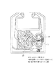
図3に示すように、収納部10では無端状のインクリボンRは、整列や巻装などされてなく単に密集した状態で収納されているので、該収納部10へ戻ったインクリボンRは当然に再度密集した状態となる。ここで、ギヤ又はローラ11を上記適切な使用方向(順回転)とは反対に回転(逆回転)させると、インクリボンRは当然に送り方向とは反対に、つまり入口部から送り出される。
As shown in FIG. 3, since the endless ink ribbon R is stored in a dense state in the
ところが、前記のとおり収納部10に戻ったインクリボンRは雑然と密集した状態で収納されているので、逆回転させるとその密集した状態のまま、例えば厚み方向に積層した状態でギヤ又はローラ11間を通過して入口部の外側に出てしまうこととなる。
However, as described above, the ink ribbon R that has returned to the
一般的に、リボンカセットRにおけるギヤ又はローラ11間の入口部の収納部10と反対の空間(以下、外側空間と記す)Sは、当然のことながら収納部10より狭く、単に戻ってくるリボンカセットRをガイドする程度の広さとされている。
In general, a space (hereinafter referred to as an outer space) S opposite to the
したがって、上記のようにギヤ又はローラ11の逆回転によって外側空間Sに出たインクリボンRは、収納部10で密集する場合と比較して激しく密集して外側空間Sを詰まらせて、また、ギヤ又はローラ11間に噛み込まれた状態のままで、インクリボンRが順方向にも逆方向にも移動しない状態となることがある。
Therefore, as described above, the ink ribbon R that has come out into the outer space S due to the reverse rotation of the gear or the
また、一旦外側空間に出たインクリボンRが前記のとおり該外側空間Sで密集した状態でギヤ又はローラ11に挟み込まれると、ギヤ又はローラ11間で順方向にも逆方向にも移動しないで詰まってしまい、かつギヤ又はローラ11自体が順回転も逆回転もしない状態となり使用不能となる。
Further, when the ink ribbon R that has once come out of the outer space is sandwiched between the gears or the
そこで、例えば以下の特許文献1〜3には、ギヤ又はローラの逆回転を防止する構成が示されている。
Therefore, for example, the following
特許文献1〜3は、いずれも対をなすギヤのうちの一方に遊星ギヤを設けて、この遊星ギヤが対をなすギヤの逆回転により連れ回されて移動するとロック用のリブと噛合して該遊星ギヤのそれ以上の逆回転を禁止し、これにより対をなすギヤの逆回転を阻止する構成である。
In each of
しかしながら、特許文献1〜3の構成は、いずれも対をなすギヤの他に遊星ギヤを設ける必要があり、逆回転を禁止するための部品数が1つ増え、コストアップに繋がると共に、リボンカセットの構造において遊星ギヤを設けるスペースが余分に必要となり、その分インクリボンの収納容量を減少させる可能性があるといった問題があった。
However, in the configurations of
解決しようとする問題点は、遊星ギヤを設けず、また、該遊星ギヤを設けるスペースを必要とせず、さらにはほとんどコストアップすることなく、ギヤ又はローラの逆回転を禁止するリボンカセットを提供することにある。 The problem to be solved is to provide a ribbon cassette that prohibits reverse rotation of a gear or a roller without providing a planetary gear, without requiring a space for providing the planetary gear, and without substantially increasing the cost. There is.
本発明は、ドットインパクトプリンタに装着されて使用されるリボンカセットであって、筐体と、この筐体内に形成され、端同士を繋いだ無端状のファブリックリボンあるいは繋ぎ目のないファブリックシームレスリボンにインクを含浸させたインクリボンを密集状態で収納する収納部と、この収納部のインクリボンの戻り部位に枢支部材を介して設けられ、対向間にインクリボンを挟み込んだ対をなす駆動部材と、対をなす駆動部材を互いに密着させるべく少なくとも一方側の枢支部材を該駆動部材の対向方向に付勢するために該枢支部材に設けた付勢部材とを備え、付勢部材を設けた側の枢支部材の付勢力に抗する移動を禁止する移動禁止部材を筐体に設けたことを最も主要な特徴とする。 The present invention relates to a ribbon cassette that is used by being mounted on a dot impact printer, and includes a casing, an endless fabric ribbon formed in the casing, and an endless fabric ribbon or a seamless fabric seamless ribbon. A storage portion for storing the ink ribbon impregnated with ink in a dense state; a drive member that is provided at a return portion of the ink ribbon of the storage portion via a pivot member and that forms a pair with the ink ribbon sandwiched between the opposing portions; An urging member provided on the pivot member for urging at least one pivot member in a direction opposite to the drive member so that the paired drive members are in close contact with each other. The main feature is that the housing is provided with a movement prohibiting member that prohibits movement against the urging force of the pivot member on the other side.
本発明は、駆動部材を逆回転させた場合において、インクリボンが収納部から積層状態で該駆動部材間を通過しようとしても、枢支部材を介して対向方向に付勢している付勢部材による駆動部材の反対向方向への移動が、移動禁止部材により禁止されるので、積層状体のインクリボンが駆動部材間に挟まって該駆動部材の逆回転を許容しない。 The present invention provides an urging member that urges an ink ribbon in an opposing direction via a pivotal member even when an ink ribbon attempts to pass between the driving members in a stacked state from a storage portion when the driving member is rotated in reverse. Since the movement of the driving member in the opposite direction is prohibited by the movement prohibiting member, the ink ribbon of the laminated body is sandwiched between the driving members and the reverse rotation of the driving member is not allowed.
したがって、駆動部材を逆回転させた際に積層状態のインクリボンが駆動部材間で挟まって逆回転が禁止されるから、該インクリボンが収納部の外側空間(筐体内において駆動部材の形成位置から見て反収納部側の空間)に積層状態のインクリボンが出ることも抑制される。 Therefore, when the drive member is rotated in the reverse direction, the stacked ink ribbon is sandwiched between the drive members and the reverse rotation is prohibited. Therefore, the ink ribbon is moved from the outer space of the storage portion (from the position where the drive member is formed in the housing). It is also possible to prevent the stacked ink ribbon from appearing in the space on the side opposite to the storage portion when viewed.
また、付勢部材を設けた側の枢支部材の付勢力に抗する移動を禁止する移動禁止部材を筐体に設けることで、駆動部材の逆回転を禁止するための別途の例えば遊星ギヤなどの駆動部材を設けること、及びそういったスペースが不要となり、ほとんどコストアップすることなく、また、インクリボンの収納量を減らすことなくギヤ又はローラの逆回転を禁止することが可能となる。 Also, a separate movement prohibiting member for prohibiting movement against the urging force of the pivot member on the side where the urging member is provided is provided on the housing, so that a separate, for example, planetary gear for prohibiting reverse rotation of the drive member, etc. In this case, it is possible to prohibit the reverse rotation of the gear or roller without substantially increasing the cost and without reducing the amount of ink ribbon stored.
本発明は、後述の実施例1において実施するための形態を示すが、ここで、用途や用語等の定義を示すこととする。本発明のリボンカセットは、ドットインパクトプリンタに装着されて使用されるものである。ドットインパクトプリンタに使用されるリボンカセットは、筐体内に、端同士を繋いだ無端状のファブリックリボンあるいは繋ぎ目のないファブリックシームレスリボンにインクを含浸させたインクリボンを密集状態で収納する収納部が形成されている。 The present invention shows a form for carrying out in Example 1 to be described later, and here, definitions of applications, terms, etc. will be shown. The ribbon cassette of the present invention is used by being mounted on a dot impact printer. Ribbon cassettes used in dot impact printers have a storage unit in the housing that stores ink ribbons that are impregnated with ink in endless fabric ribbons that are end-to-end or seamless fabric ribbons that are seamless. Is formed.
密集状態とは、例えば巻装したり、蛇腹状に整列したり、といった整然と規則正しく収納されてはなく、単に押し込まれたような状態を意味する。収納部の送り側はドットインパクトプリンタの印刷部位へとインクリボンが送られる側で、戻り側はドットインパクトプリンタの印刷部位からインクリボンが戻ってくる側を意味する。 The dense state means a state in which, for example, it is not pushed in or arranged in an accordion-like manner but is stored in an orderly manner and is simply pushed in. The feeding side of the storage unit is the side where the ink ribbon is fed to the printing site of the dot impact printer, and the return side is the side where the ink ribbon returns from the printing site of the dot impact printer.
すなわち対をなす駆動部材は、収納部の戻り部位に枢支部材を介して設けられている。駆動部材は例えばギヤであってもローラであってもよい。対向間とは、対をなす駆動部材同士の間を意味し、ここにインクリボンが挟み込まれる。 That is, the paired drive members are provided at the return portion of the storage portion via the pivot member. The drive member may be a gear or a roller, for example. The term “between facing” means between a pair of drive members, and an ink ribbon is sandwiched between them.
対をなす駆動部材を各々枢支した枢支部材は筐体に設けられ、少なくとも一方側には、対をなす駆動部材を対向方向に互いに密着させるべく、付勢部材が設けられている。付勢部材は例えばばねなどの弾性体を採用することができる。 A pivot member that pivotally supports each pair of drive members is provided on the casing, and at least one side is provided with a biasing member so that the pair of drive members are in close contact with each other. For example, an elastic body such as a spring can be adopted as the biasing member.
そして、移動禁止部材は、筐体に設けたものであって、付勢部材を設けた側の枢支部材の付勢力に抗する移動、すなわち、駆動部材の反対向方向への一定量以上の移動を禁止する。 The movement prohibiting member is provided on the housing and moves against the urging force of the pivot member on the side where the urging member is provided, that is, a certain amount or more in the opposite direction of the driving member. Prohibit movement.
さらに、本発明のリボンカセットは、移動禁止部材に関して、筐体を開閉可能な構造とし、この筐体における蓋側に設ければよい。こうすると、蓋を開けて作業をする際には、移動禁止部材による駆動部材の反対向方向への移動の禁止が解除されるから、対向間隔に余裕が生じ、例えば使用済みのインクリボンを駆動部材間から抜いて、新たなインクリボンを駆動部材の対向間に挿入するといった、入れ替え等の作業がしやすくなる。 Furthermore, the ribbon cassette of the present invention may have a structure in which the casing can be opened and closed with respect to the movement prohibiting member, and may be provided on the lid side of the casing. In this way, when the work is performed with the lid open, the prohibition of the movement of the driving member in the opposite direction by the movement prohibiting member is released, so that there is a margin in the facing interval, for example, driving the used ink ribbon It is easy to perform operations such as exchanging, such as removing from between the members, and inserting a new ink ribbon between the facing members of the drive member.
そして、本発明のリボンカセットにおける移動禁止部材は、1枚分の厚みのファブリックリボンが通過する駆動部材の付勢状態を基準として、2〜7枚分の厚みだけ枢支部材を介した駆動部材の反対向方向への移動を許容する位置に設ければよい。 And the movement prohibition member in the ribbon cassette of the present invention is a drive member that has a thickness of 2 to 7 sheets via the pivotal support member based on the biased state of the drive member through which the fabric ribbon of one sheet thickness passes. What is necessary is just to provide in the position which accept | permits the movement to the opposite direction.
上記移動許容量は、例えば1枚分の厚み以上を許容しないこととすると、駆動部材や筐体材料の成形誤差が許されないこととなり、場合によっては1枚分のインクリボンが通過する順送りの場合も駆動部材が駆動しない場合もあり得る。一方、例えば7枚を超える厚みを許容すると、場合によっては断続的な積層状態のインクリボンが収納部の外側空間に出てしまうことがあり得る。 For example, if the movement allowance is not allowed to exceed the thickness of one sheet, molding errors in the drive member and housing material are not permitted. However, the drive member may not be driven. On the other hand, if a thickness exceeding 7 sheets is allowed, for example, an intermittently laminated ink ribbon may come out in the outer space of the storage unit.
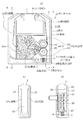
以下に図1及び図2を参照して、本発明のリボンカセットについて説明する。図1(a)及び図2では、筐体の本体側の底部(蓋側と反対面)の図示を省略している。本発明のリボンカセット1は、不図示のドットインパクトプリンタに装着され、筐体2内に、端同士を繋いだ無端状のファブリックリボンにインクを含浸させたインクリボンRを収納している。
Hereinafter, the ribbon cassette of the present invention will be described with reference to FIGS. 1 and 2. In FIG. 1A and FIG. 2, illustration of a bottom portion (a surface opposite to the lid side) on the main body side of the housing is omitted. A
筐体2は、本体2Aと蓋2Bとからなり、本実施例では開閉可能とされている。筐体2は、全体として略矩形状とされ、図1(a)で示す上部で幅方向中央に空間Pが形成され、ここで露出しているインクリボンRが、該空間P近傍に位置するドットインパクトプリンタの印字部により印刷に供される。インクリボンRはドットインパクトプリンタの印字部へ送られて使用され、筐体2内に戻る。
The
筐体2は、幅方向の図1(a)に示す左側にインクリボンRが印字部に送られる送り経路1aが形成され、幅方向の図1(a)に示す右側にインクリボンRが印字部を経て戻される戻り経路1bが形成されている。
The
筐体2の下部には、収納部2Cが形成されている。収納部2Cは、図1(a)に示す、右側を該収納部2Cへ戻る入口とし、左側を該収納部2Cから印字部へ送られる出口とされている。この収納部2Cには、入口から戻ったインクリボンRが密集状態で収納されている。
A
筐体2の収納部2Cにおける出口側には、図1(c)に示すように、本体2Aと蓋2Bの対向面に互いに対向方向に若干だけ突出した堰部2Aa,2Baが形成されている。インクリボンRは堰部2Aa,2Baにより幅方向の端部が引っ掛かって収納部2Cに止まる。一方、収納部2Cの出口側から送り出されるインクリボンRは、引き出される力により幅方向に変形して堰部2Aa,2Ba間から引き出されるようになっている。
As shown in FIG. 1C, weir portions 2Aa and 2Ba are formed on the opposing surfaces of the
筐体2における本体2A側の収納部2Cにおける入口側には、枢支部材3が設けられ、この枢支部材3は、図1(a)(b)における上下の高さ方向に枢支部材3A,3Bで対をなしている。すなわち、枢支部材3A,3Bは、図1(a)に示すように本実施例では平面視略直角三角形状とされ、斜辺が収納部2Cに臨むように設けられている。こうすることで、収納部2Cの入口から出口にかけてインクリボンRが入口近傍に止まることなく速やかに送られる。
A
枢支部材3には駆動部材4が設けられ、本実施例では、枢支部材3A,3Bの収納部2Cの入口を形成する部位に、例えば駆動部材として対をなすギヤ4(ギヤ4A,4B)が噛合するように各々枢支されている。
The
枢支部材3A,3Aのうち本実施例では図示下側の一方の枢支部材3Bは、本体2Aに設けられた枢支軸3bにより枢支され、これを中心に該枢支部材3Bが傾動する。そして、枢支部材3Bの下端で枢支軸3bを設けた側と反対の端部(入口側)と、本体2Aの上下方向の下内面との間には、付勢部材としての例えば本実施例では巻きばね5を介設している。
In this embodiment, one of the
すなわち、ギヤ4A,4Bは、ギヤ4Aに対してギヤ4Bが、巻きばね5により枢支部材3Bを介して対向方向(ギヤ4A方向)に付勢されており、インクリボンRはこれらギヤ4A,4B間に通されている。
That is, the
上記枢支部材3Bの下端で枢支軸3bを設けた側と反対の端部(入口側)と、本体2Aの上下方向の下内面との間には、該枢支部材3Bの傾動ストロークを一定範囲内に規制する、すなわち該枢支部材3Bの一定量以上の傾動を禁止する、移動禁止部材6が設けられている。この移動禁止部材6は、筐体2における蓋2Bに設けられており、蓋2Bを開けることで、該移動禁止部材6による枢支部材3Bの傾動ストロークの制限を解除する構成とされている。
The tilting stroke of the
移動禁止部材6は、本実施例では、例えばインクリボンRの1枚分の厚みを基準として、本実施例では例えばインクリボンRの2枚分の厚み分だけ枢支部材3Bが傾動することができる位置に設けている。すなわち、ギヤ4A,4B間に2枚より厚い状態で積層したインクリボンRが噛み込まれた場合は、傾動した枢支部材3Bが移動禁止部材6と当接して、該枢支部材3Bがそれ以上傾動することを許容しない構成とされている。
In the present embodiment, for example, the movement prohibiting member 6 is configured such that the
上記構成のリボンカセット1は、ギヤ4A,4B、本実施例の場合は、ギヤ4Aがドットインパクトプリンタによって順方向に回転駆動されると、該ギヤ4A,4Bに噛み込まれているインクリボンRが順次、収納部2Cに戻されると同時に、このテンションにより、収納部2Cの出口側からインクリボンRが送り出される。
The
例えばドットインパクトプリンタからリボンカセット1を取り外して、使用者が誤ってギヤ4Aを逆方向に回転させると、次のように動作してトラブルが抑制される。すなわち、収納部2Cにおいては、入口側からはインクリボンRが整然と(積層されることなく)収納され、該収納部2C内において密集状態となる。
For example, when the
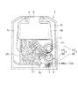
ギヤ4A,4Bを逆回転させると、収納部2Cから密集状態のインクリボンRが入口側から出ようとする。このとき、上述のとおり収納部2CではインクリボンRが密集しているので、図2に示すように、容易に積層した状態で該ギヤ4A,4B間に噛み込まれることとなる。
When the
本実施例ではインクリボンRの2枚分の厚みを超える、積層されたインクリボンRがギヤ4A,4Bに噛み込まれると、その分だけ、枢支部材3Bが巻きばね5の付勢力に抗して傾動して移動禁止部材6に当接して、それ以上の傾動が許容されない。
In this embodiment, when the laminated ink ribbon R exceeding the thickness of two ink ribbons R is bitten by the
逆回転の初期に、積層されたインクリボンRがギヤ4B,4Bに噛み込まれた状態になると、つまりギヤ4A,4Bにおける収納部2Cから入口へ向けた噛み込み初期の状態で、移動禁止部材6と枢支部材3Bとが当接すると、ギヤ4A,4Bのそれ以上の逆回転は禁止され、このとき順回転させることで未だ完全にギヤ4A,4Bの対向間に達していない積層されたインクリボンRは収納部2Cに戻り、再度通常の使用が可能となる。
When the stacked ink ribbon R is in a state of being engaged with the
すなわち、本実施例における移動禁止部材6は、積層されたインクリボンRがギヤ4A,4Bの対向間に達する前に、そのような挙動を察知して動作するように設定されている。枢支部材3Bの傾動許容量として本実施例で設定したインクリボンRの厚み2枚分は、次の意味がある。無端状のインクリボンRは積層状態では厚み2枚での積層はなく、積層されるとすれば最小単位でも厚み3枚分となる。
That is, the movement prohibiting member 6 in the present embodiment is set so as to operate by detecting such behavior before the stacked ink ribbon R reaches between the
したがって、本実施例のように、移動禁止部材6は、積層されたインクリボンRの例えば2枚分の厚み分だけ枢支部材3Bの傾動を許容する位置に設けておけば、密着状態(例えば3枚分の厚みちょうど)で積層されたとしても、上述のように積層されたインクリボンRがギヤ4A,4Bの対向間に達する前に逆回転が禁止され、順回転すればインクリボンRは収納部2Cに戻り、再度通常の使用が可能となる。
Therefore, as in this embodiment, if the movement prohibiting member 6 is provided at a position that allows the pivoting
逆に例えば移動禁止部材6の位置を、例えばインクリボンRの1枚分の厚み分だけ枢支部材3Bの傾動を許容する位置とすると、あまりにも傾動許容量が小さすぎて、例えばギヤ4A,4Bの成型誤差等によっても回転が禁止されてしまう場合が生じ、順回転も逆回転も不可能となる可能性がある。
On the contrary, for example, if the position of the movement prohibiting member 6 is set to a position that allows the tilting of the
一方、7枚を超える厚み分の位置に移動禁止部材6を設けると、3枚、5枚、7枚に積層されたインクリボンRがギヤ4A,4Bの対向間に達することはもちろん、そのように積層されたインクリボンRが順次逆回転させるだけ止まることなくギヤ4A,4Bの対向間を超えて収納部2Cの入口より外側へ出る可能性、つまり逆回転禁止の効果がほとんど無くなる可能性がある。
On the other hand, when the movement prohibiting member 6 is provided at a position corresponding to the thickness exceeding 7 sheets, the ink ribbon R stacked on 3 sheets, 5 sheets, and 7 sheets reaches the gap between the
上限値とする7枚の厚み分の位置に移動禁止部材6を設けた場合、例えば5枚積層されたインクリボンRはギヤ4A,4Bの対向間を通過が可能であるが、実際には、逆転を続けると、収納部2C側ではインクリボンRの密度が高いので、すぐに7枚より多く積層されたインクリボンRが、ギヤ4A,4Bの対向間に入り込もうとし、逆回転がその時点で禁止される。
When the movement prohibiting member 6 is provided at a position corresponding to the thickness of seven sheets as the upper limit value, for example, five stacked ink ribbons R can pass between the
つまり、インクリボンRの例えば7枚(上限値)の厚み分だけ枢支部材3Bの傾動を許容する位置に移動禁止部材6を設けた場合は、本実施例のように2枚の厚み分の位置に移動禁止部材6を設けた場合のようなギヤ4A,4Bの対向間に達する前に逆転を即時禁止するといった効果は若干低下するものの、積層されたインクリボンRが例えば数ミリだけ収納部2Cの入口部より外側に出たとしても、その後には、上記のとおり逆転が確実に禁止される。
That is, when the movement prohibiting member 6 is provided at a position where the tilt of the
また、移動禁止部材6は蓋2B側に設けているが、この理由は、例えばインクリボンRだけを取り替えるような作業をする際に、本体2Aに移動禁止部材6が設けられていると、蓋2Bを開けても移動禁止部材6による枢支部材3Bの傾動禁止状態が解除されないからである。
The movement prohibiting member 6 is provided on the
したがって、移動禁止部材6を蓋2B側に設けておくことで、該蓋2Bを開けることで枢支部材3Bの傾動禁止状態が解除され、巻きばね5の最大に圧縮するまでギヤ4A,4Bの対向間を広くすることができ、該ギヤ4A,4Bの対向間に取り替えたインクリボンRを挿入しやすくなる。
Therefore, by providing the movement prohibiting member 6 on the
また、本発明のリボンカセット1は、ギヤ4A,4Bの逆回転を禁止するために例えば遊星ギヤなどの比較的大きな部材を新たに備える構成ではないので、筐体2内の特に収納部2Cを圧迫することがなく、多くのインクリボンRを収納しておくことができると共に、別部材の追加コストが不要となる。
Further, since the
1 リボンカセット
2 筐体
2A 本体
2B 蓋
2C 収納部
3 枢支部材
3A 枢支部材
3B 枢支部材
4 ギヤ(駆動部材)
4A ギヤ
4B ギヤ
5 巻きばね(付勢部材)
6 移動禁止部材
R インクリボン
DESCRIPTION OF
6 Movement prohibition member R Ink ribbon
Claims (2)
Priority Applications (1)
| Application Number | Priority Date | Filing Date | Title |
|---|---|---|---|
| JP2010163024A JP5785699B2 (en) | 2010-07-20 | 2010-07-20 | Ribbon cassette |
Applications Claiming Priority (1)
| Application Number | Priority Date | Filing Date | Title |
|---|---|---|---|
| JP2010163024A JP5785699B2 (en) | 2010-07-20 | 2010-07-20 | Ribbon cassette |
Publications (2)
| Publication Number | Publication Date |
|---|---|
| JP2012024946A true JP2012024946A (en) | 2012-02-09 |
| JP5785699B2 JP5785699B2 (en) | 2015-09-30 |
Family
ID=45778497
Family Applications (1)
| Application Number | Title | Priority Date | Filing Date |
|---|---|---|---|
| JP2010163024A Ceased JP5785699B2 (en) | 2010-07-20 | 2010-07-20 | Ribbon cassette |
Country Status (1)
| Country | Link |
|---|---|
| JP (1) | JP5785699B2 (en) |
Cited By (1)
| Publication number | Priority date | Publication date | Assignee | Title |
|---|---|---|---|---|
| JP2014221303A (en) * | 2012-03-08 | 2014-11-27 | 株式会社新興製作所 | Abrasive cassette |
Citations (5)
| Publication number | Priority date | Publication date | Assignee | Title |
|---|---|---|---|---|
| JPS62294580A (en) * | 1986-06-14 | 1987-12-22 | Canon Inc | ink ribbon cassette |
| JPH0191564U (en) * | 1987-12-10 | 1989-06-15 | ||
| JPH0370956U (en) * | 1989-11-15 | 1991-07-17 | ||
| JPH0483658U (en) * | 1990-11-29 | 1992-07-21 | ||
| JPH06247019A (en) * | 1993-02-26 | 1994-09-06 | Tokyo Electric Co Ltd | Ink ribbon cassette |
-
2010
- 2010-07-20 JP JP2010163024A patent/JP5785699B2/en not_active Ceased
Patent Citations (5)
| Publication number | Priority date | Publication date | Assignee | Title |
|---|---|---|---|---|
| JPS62294580A (en) * | 1986-06-14 | 1987-12-22 | Canon Inc | ink ribbon cassette |
| JPH0191564U (en) * | 1987-12-10 | 1989-06-15 | ||
| JPH0370956U (en) * | 1989-11-15 | 1991-07-17 | ||
| JPH0483658U (en) * | 1990-11-29 | 1992-07-21 | ||
| JPH06247019A (en) * | 1993-02-26 | 1994-09-06 | Tokyo Electric Co Ltd | Ink ribbon cassette |
Cited By (1)
| Publication number | Priority date | Publication date | Assignee | Title |
|---|---|---|---|---|
| JP2014221303A (en) * | 2012-03-08 | 2014-11-27 | 株式会社新興製作所 | Abrasive cassette |
Also Published As
| Publication number | Publication date |
|---|---|
| JP5785699B2 (en) | 2015-09-30 |
Similar Documents
| Publication | Publication Date | Title |
|---|---|---|
| JP5426685B2 (en) | Cartridge type media holding mechanism | |
| CN105934350B (en) | Integral ink cartridge and portable printing machine using the integral ink cartridge | |
| JP4997125B2 (en) | Printer | |
| CN106132712B (en) | Tape printing apparatus and with print system | |
| JP5440018B2 (en) | Tape cartridge | |
| JP7711733B2 (en) | cassette | |
| JP5908292B2 (en) | Printer and paper guide mechanism thereof | |
| JP2011207548A (en) | Roll paper printer and method of opening-closing roll paper printer cover | |
| JP5785699B2 (en) | Ribbon cassette | |
| CN113573910B (en) | box and printing unit | |
| JP5233923B2 (en) | Tape cassette | |
| JP5799981B2 (en) | Printing device | |
| CN109328141B (en) | printer | |
| JP5985864B2 (en) | Printer and its paper guide mechanism | |
| JP6046101B2 (en) | Sheet cassette and image forming apparatus having the same | |
| JP2020157478A (en) | Printer | |
| JP6894336B2 (en) | Printer | |
| JP5462297B2 (en) | Paper storage device and printer | |
| JP5793306B2 (en) | Ribbon cassette | |
| JP3334516B2 (en) | Ink film cassette and reel used for ink film cassette | |
| JP7545666B2 (en) | Printing device | |
| JP5408296B2 (en) | Recording device | |
| JP2017052157A (en) | Printer | |
| JP5732022B2 (en) | Image forming apparatus | |
| JP4123107B2 (en) | Medium transport mechanism and printer with information reading means |
Legal Events
| Date | Code | Title | Description |
|---|---|---|---|
| A621 | Written request for application examination |
Free format text: JAPANESE INTERMEDIATE CODE: A621 Effective date: 20130704 |
|
| A977 | Report on retrieval |
Free format text: JAPANESE INTERMEDIATE CODE: A971007 Effective date: 20140327 |
|
| A131 | Notification of reasons for refusal |
Free format text: JAPANESE INTERMEDIATE CODE: A131 Effective date: 20140408 |
|
| A521 | Written amendment |
Free format text: JAPANESE INTERMEDIATE CODE: A523 Effective date: 20140530 |
|
| A131 | Notification of reasons for refusal |
Free format text: JAPANESE INTERMEDIATE CODE: A131 Effective date: 20141209 |
|
| A521 | Written amendment |
Free format text: JAPANESE INTERMEDIATE CODE: A523 Effective date: 20150205 |
|
| TRDD | Decision of grant or rejection written | ||
| A01 | Written decision to grant a patent or to grant a registration (utility model) |
Free format text: JAPANESE INTERMEDIATE CODE: A01 Effective date: 20150630 |
|
| A61 | First payment of annual fees (during grant procedure) |
Free format text: JAPANESE INTERMEDIATE CODE: A61 Effective date: 20150727 |
|
| R150 | Certificate of patent or registration of utility model |
Ref document number: 5785699 Country of ref document: JP Free format text: JAPANESE INTERMEDIATE CODE: R150 |
|
| RVOP | Cancellation by post-grant opposition | ||
| R157 | Certificate of patent or utility model (correction) |
Free format text: JAPANESE INTERMEDIATE CODE: R157 |