JP2012024913A - Blade edge grinder of doctor blade for gravure printing machine - Google Patents
Blade edge grinder of doctor blade for gravure printing machine Download PDFInfo
- Publication number
- JP2012024913A JP2012024913A JP2010180574A JP2010180574A JP2012024913A JP 2012024913 A JP2012024913 A JP 2012024913A JP 2010180574 A JP2010180574 A JP 2010180574A JP 2010180574 A JP2010180574 A JP 2010180574A JP 2012024913 A JP2012024913 A JP 2012024913A
- Authority
- JP
- Japan
- Prior art keywords
- doctor blade
- doctor
- polishing
- grinding
- blade
- Prior art date
- Legal status (The legal status is an assumption and is not a legal conclusion. Google has not performed a legal analysis and makes no representation as to the accuracy of the status listed.)
- Pending
Links
- 238000007646 gravure printing Methods 0.000 title description 2
- 238000000034 method Methods 0.000 claims abstract 3
- 238000005498 polishing Methods 0.000 claims description 41
- 238000007730 finishing process Methods 0.000 claims 1
- 238000007639 printing Methods 0.000 abstract description 12
- 238000004519 manufacturing process Methods 0.000 abstract 1
- 239000007788 liquid Substances 0.000 description 4
- 238000010586 diagram Methods 0.000 description 2
- 238000012790 confirmation Methods 0.000 description 1
Images


Landscapes
- Grinding And Polishing Of Tertiary Curved Surfaces And Surfaces With Complex Shapes (AREA)
Abstract
Description
この発明はドクターブレードの刃先の形状を平面研磨機、円筒研磨機で理想的な刃先形状に研磨する事が出来る研磨機に関するものである。The present invention relates to a polishing machine that can polish the shape of the blade edge of a doctor blade to an ideal blade edge shape with a flat surface polishing machine or a cylindrical polishing machine.
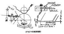
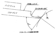
新品のドクターブレードを使用し印刷を開始すると刃先は摩耗を始める、一様に摩耗すれば問題ないが、円筒版は凹形彫刻してある所と、凹部以外の平面の所が遍在しているので場所により摩耗量が異なる。このためドクターブレード刃先は長手方向に波状に摩耗していく、この摩耗が限界をこえるとインクのかきとりが出来ず印刷物が汚れて使用できなくなる。
この場合新品のドクターブレードに交換すると部品コストと交換作業時間がかかる。 摩耗した刃先を修正する機械が現在ないので、ドクターブレードをドクターホルダーごと万力にくわえ、熟練技術者の感で砥石とサンドペーパーで修正して再使用している。(ドクターブレード先端厚さは50ミクロンしかなく、この先端を60度の角度を付けで研磨する必要があり、神業的作業であり、危険である。)再研磨しても正確に研磨出来たか確認する方法もなく、実際に印刷してみないと結果の良否が判らない。When printing is started using a new doctor blade, the cutting edge starts to wear, and if it wears evenly, there is no problem, but the cylindrical plate has a concave sculpture and a plane other than the recess is ubiquitous. The amount of wear varies depending on the location. For this reason, the blade edge of the doctor blade is worn in a wave shape in the longitudinal direction. If this wear exceeds the limit, the ink cannot be scraped off and the printed matter becomes dirty and cannot be used.
In this case, replacement with a new doctor blade requires parts cost and replacement work time. There is currently no machine for repairing worn edges, so doctor blades are added to the doctor holder in a vise and are re-used with a grindstone and sandpaper with the feeling of a skilled technician. (The doctor blade tip thickness is only 50 microns, and it is necessary to polish the tip at an angle of 60 degrees, which is a theological work and is dangerous.) There is no way to do this, and if you don't actually print it, you won't know the result.
摩耗したドクターブレードの修正を熟練技術者の感にたより砥石とサンドペーパーで仕上げていては、印刷品質の確保と向上も望めないので刃先修正研磨機械を考案する必要がある。この場合修正したドクターブレードが印刷前に正確に復元出来たか同時に計測出来ることが必要である。If a worn doctor blade is finished with a grindstone and sandpaper according to the feeling of a skilled engineer, it is not possible to secure and improve the printing quality, so it is necessary to devise an edge-correcting polishing machine. In this case, it is necessary to measure at the same time whether the modified doctor blade has been correctly restored before printing.
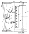
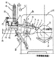
本研磨機械の構成は図1、図2に示すように平面研磨機と円筒研磨機が一緒に組み込まれた構造になっている。
「平面研磨」
平面研磨はドクターアーム6がBの位置にあり、ドクターブレード1の研磨面が真上を向いた状態で研磨する。ドクターシャフト7には角度計がついており刃先研磨角度を見る事ができる。研磨砥石12はボールジョイント13で保持角パイプ14に取付られているので左右に揺動できる。保持角パイプ14はスライドレール15に取付られており、上下に自由にスライドできる。したがってドクターブレード1の研磨面には砥石12、保持角パイプ14、とスライドレール15の合計重量が作用する事になる(必要があれば錘を追加する事により自由に調整できる。)
研磨砥石12は保持プレート16で電動スライドレール17に取付られている。
電動スライドレール17は電動で水平に左右に往復スライドする機能を持っている以上の通り研摩砥石12はドクターブレード1の先端面を移動し研削する。
ここで研摩砥石12の研磨面が全面的に摩耗するように電動スライドレールは傾けて設置してあります。
なお平面研磨はドクターブレード1の波型摩耗を修正するためのもので研磨面は粗いので最終仕上げとして、次に説明する円筒研磨を行う。
「円筒研磨」
円筒研磨はドクタクターアーム6がAの位置にある状態で行う。
円筒研磨は研磨ドラム9と研磨液体10で行いドクターブレード1を研磨ドラム9に押し付けて研磨ドラム9を回転させて行う。研磨ドラムは全面に彫刻されておりこのみぞに研磨液体10がはいりドクターブレードの先端を研磨する。
この研磨状態は丁度印刷機で印刷する状態と同じ条件に設定すれば理想的な研磨が出来る。
「研磨作業の確認」
円筒研磨終了直前にドクター先端面圧調整錘11を軽くしていくと研磨液体10が研磨ドラム9に均一に塗布されれば完了です。均一ではなく斑になるようでしたら再度円筒研磨を行います。均一になるまで円筒研磨すればドクターブレード1は波型摩耗はなくドクターブレード1の先端は真直ぐに研磨された事になります。As shown in FIGS. 1 and 2, the polishing machine has a structure in which a plane polishing machine and a cylindrical polishing machine are incorporated together.
"Surface polishing"
Surface polishing is performed with the doctor arm 6 at the position B and the polishing surface of the
The grinding
The electric slide rail 17 has a function of electrically reciprocating horizontally to the left and right. As described above, the
Here, the electric slide rail is tilted so that the polishing surface of the grinding
The flat surface polishing is for correcting the wave wear of the
"Cylinder polishing"
Cylindrical polishing is performed with the doctor arm 6 in the position A.
Cylindrical polishing is performed with the
This polishing state can be ideally polished by setting the same conditions as those for printing with a printing machine.
"Confirmation of polishing work"
If the doctor tip surface pressure adjustment weight 11 is lightened just before the end of cylindrical polishing, the
印刷開始前にドクターブレードを理想的な形状に仕上げてあるので、印刷試験運転時間が短く、定常運転に移行できるので作業時間の短縮と印刷歩留が向上できる。
従来のドクターブレード先端を砥石とサンドペーパーを使って手作業で感をたよりに研磨しなくてすみ熟練作業者が不要になる。
印刷の時間経過によるドクターブレード1の摩耗状態が安定しているので楽に作業ができる。Since the doctor blade is finished in an ideal shape before the start of printing, the printing test operation time is short and the operation can be shifted to the steady operation, so that the working time can be shortened and the printing yield can be improved.
The conventional doctor blade tip does not need to be polished manually by using a grindstone and sandpaper, making it unnecessary for skilled workers.
Since the wear state of the
上記発明を実証すべく試作機(添付写真1)を製作しドクターブレード先端の修正研磨し、顕微鏡にて形状を測定した結果理想的な形状に研磨出来る事が確認できた。
なおこのドクターブレードを印刷機に装着し実際に使用した結果試運転時間が短く定常運転に早く移行できた。 印刷中も状態が安定しており作業者が楽になった。
この結果ドクターブレードの再研磨が可能になり寿命が従来の比べ3〜4倍に伸びた。In order to demonstrate the above invention, a prototype (Attached Photo 1) was manufactured, the tip of the doctor blade was corrected and polished, and the shape was measured with a microscope. As a result, it was confirmed that it could be polished into an ideal shape.
In addition, as a result of using this doctor blade in a printing press and actually using it, the test run time was short and it was possible to shift to steady operation quickly. The situation was stable during printing, and the operator became easier.
As a result, the doctor blade can be re-polished, and the lifetime has been increased 3 to 4 times compared to the conventional one.
1 ドクターブレード
2 バックプレート
3 ドクターホルダー(上)
4 ドクターホルダー(下)
5 スライドプレート
6 ドクターアーム
7 ドクターシャフト
8 ドクタースライド調整ノブ
9 研磨ドラム
10 研磨液体
11 ドクター先端面圧調整錘
12 研磨砥石
13 ボールジョイント
14 保持角パイプ
15 スライドレール
16 保持プレート
17 電動スライドレール
18 スライドレール保持パイプ
19 固定ノブ
20 支持受け右
21 支持受け左
22 メインフレーム
A 円筒研磨状態でのドクター位置
B 平面研磨状態でのドクター位置1
4 Doctor holder (bottom)
DESCRIPTION OF SYMBOLS 5 Slide plate 6 Doctor arm 7 Doctor shaft 8 Doctor
Claims (4)
Priority Applications (1)
| Application Number | Priority Date | Filing Date | Title |
|---|---|---|---|
| JP2010180574A JP2012024913A (en) | 2010-07-27 | 2010-07-27 | Blade edge grinder of doctor blade for gravure printing machine |
Applications Claiming Priority (1)
| Application Number | Priority Date | Filing Date | Title |
|---|---|---|---|
| JP2010180574A JP2012024913A (en) | 2010-07-27 | 2010-07-27 | Blade edge grinder of doctor blade for gravure printing machine |
Publications (1)
| Publication Number | Publication Date |
|---|---|
| JP2012024913A true JP2012024913A (en) | 2012-02-09 |
Family
ID=45778476
Family Applications (1)
| Application Number | Title | Priority Date | Filing Date |
|---|---|---|---|
| JP2010180574A Pending JP2012024913A (en) | 2010-07-27 | 2010-07-27 | Blade edge grinder of doctor blade for gravure printing machine |
Country Status (1)
| Country | Link |
|---|---|
| JP (1) | JP2012024913A (en) |
Cited By (2)
| Publication number | Priority date | Publication date | Assignee | Title |
|---|---|---|---|---|
| CN105563265A (en) * | 2016-01-21 | 2016-05-11 | 苏州经贸职业技术学院 | Automatic edge grinding machine for frame body |
| CN106378696A (en) * | 2016-12-14 | 2017-02-08 | 王朝永 | Automatic polishing machine for bent pipe |
-
2010
- 2010-07-27 JP JP2010180574A patent/JP2012024913A/en active Pending
Cited By (2)
| Publication number | Priority date | Publication date | Assignee | Title |
|---|---|---|---|---|
| CN105563265A (en) * | 2016-01-21 | 2016-05-11 | 苏州经贸职业技术学院 | Automatic edge grinding machine for frame body |
| CN106378696A (en) * | 2016-12-14 | 2017-02-08 | 王朝永 | Automatic polishing machine for bent pipe |
Similar Documents
| Publication | Publication Date | Title |
|---|---|---|
| CN106944929B (en) | Workpiece polishing method and polishing pad dressing method | |
| US20180056475A1 (en) | Method for producing substrate | |
| US20090203296A1 (en) | Device and method for truing a machining wheel by means of a rotating truing tool as well as machine tool with a device of this kind | |
| DK2170560T3 (en) | A grinder used in particular for grinding flat, concave and convex surfaces, and the method for using it. | |
| JP5526895B2 (en) | Manufacturing method of large synthetic quartz glass substrate | |
| CN102773803A (en) | Precise finishing method of large abrasive grain diamond grinding wheel | |
| KR20160051219A (en) | Conditioner of chemical mechanical polishing apparatus capable of roughness deviation on polishing pad surface | |
| JP2012024913A (en) | Blade edge grinder of doctor blade for gravure printing machine | |
| JP2001293646A (en) | Rough grinding machine equipped with optical element grinding method and truing device | |
| TW201524686A (en) | Dressing method and dressing device | |
| JP4702765B2 (en) | Vibration polishing method and apparatus | |
| JP2010058203A (en) | Lapping device for single-crystalline diamond | |
| JP4853061B2 (en) | Doctor blade polishing apparatus and doctor blade polishing method | |
| JP2015532898A5 (en) | ||
| CN220740774U (en) | Knife sharpener | |
| CN216802740U (en) | Clamping piece device for knife grinder | |
| JP6202458B1 (en) | Gravure printing plate, method for producing gravure printing plate and gravure printing method | |
| CN104347357A (en) | Substrate machining method with polishing and follow-up cleaning being replaced by thinning | |
| KR101467450B1 (en) | Apparatus for grinding screen print squeegee | |
| JP2006075926A (en) | Cylinder type grinding wheel, doctor blade polishing apparatus and method | |
| JP6002160B2 (en) | Paper polishing method and paper polishing apparatus for gravure printing roll | |
| KR100759111B1 (en) | Grinding machine with automatic correction | |
| JP4136258B2 (en) | How to correct the shape of a concave shaped tool | |
| JP2010120147A (en) | Coaxiality adjusting method and polishing device | |
| KR20020041845A (en) | The Grinder and Grinding Method of Trimming Knife |