JP2012024908A - Assembling method by weld-bonding - Google Patents
Assembling method by weld-bonding Download PDFInfo
- Publication number
- JP2012024908A JP2012024908A JP2010168566A JP2010168566A JP2012024908A JP 2012024908 A JP2012024908 A JP 2012024908A JP 2010168566 A JP2010168566 A JP 2010168566A JP 2010168566 A JP2010168566 A JP 2010168566A JP 2012024908 A JP2012024908 A JP 2012024908A
- Authority
- JP
- Japan
- Prior art keywords
- welding
- assembly
- jig
- heat
- members
- Prior art date
- Legal status (The legal status is an assumption and is not a legal conclusion. Google has not performed a legal analysis and makes no representation as to the accuracy of the status listed.)
- Pending
Links
Images

Landscapes
- Automobile Manufacture Line, Endless Track Vehicle, Trailer (AREA)
- Automatic Assembly (AREA)
Abstract
【課題】コストを抑えた簡便な組み立て手法であって、かつ、設計上の条件を満足し得る溶接接合による組立方法を提案する。
【解決手段】溶接接合による組立方法は、仮組立工程と、溶接工程と、加熱工程とを含んでいる。仮組立工程は、溶接接合する部材21、22、23を組立治具30にセットし、加熱処理によって接着力が低下して剥離可能な熱剥離型接着剤36によって仮止めして仮組立体31を形成する工程である。溶接工程は、仮組立体を溶接治具40にセットし、部材同士を溶接接合して接合体41を形成する工程である。加熱工程は、接合体を加熱処理して熱剥離型接着剤を剥離して組立体51を得る工程である。
【選択図】図1The present invention proposes an assembling method by welding joining, which is a simple assembling method with reduced cost and can satisfy design conditions.
An assembly method by welding joining includes a temporary assembly process, a welding process, and a heating process. In the temporary assembly step, the members 21, 22, and 23 to be welded are set on the assembly jig 30, and temporarily fixed with a heat-peelable adhesive 36 that can be peeled off due to a decrease in the adhesive force due to the heat treatment. Is a step of forming. The welding process is a process in which the temporary assembly is set on the welding jig 40 and the members are welded together to form the joined body 41. The heating step is a step in which the assembly 51 is obtained by heat-treating the bonded body to peel off the heat-peeling adhesive.
[Selection] Figure 1
Description
本発明は、溶接接合による組立方法に関する。 The present invention relates to an assembly method by welding.
周知のように、自動車車体は、鋼板からなるフロアメイン、ボディサイド、ルーフレールなどの複数の部材を溶接治具にセットし、部材同士を溶接接合して組み立てている(例えば、特許文献1を参照)。溶接治具には、部材同士の相対位置を定めて固定するクランプ装置が設けられている。クランプ装置によって部材を溶接治具に固定した状態で、スポット溶接などによって部材同士を溶接接合する。溶接治具と溶接ガンとが干渉することなどによって、溶接治具に部材を固定した状態のままでは溶接できない箇所が生じることがある。このような場合には、溶接治具内において溶接し終わったワークを溶接治具から取り出し、溶接治具外において、溶接できなかった打点について増し打ち溶接を行っている。 2. Description of the Related Art As is well known, an automobile body is assembled by setting a plurality of members such as a floor main, a body side, and a roof rail made of steel plates on a welding jig and welding the members together (see, for example, Patent Document 1). ). The welding jig is provided with a clamp device that determines and fixes the relative positions of the members. The members are welded together by spot welding or the like with the members fixed to the welding jig by the clamp device. Due to the interference between the welding jig and the welding gun, there may be a portion that cannot be welded with the member fixed to the welding jig. In such a case, the workpieces that have been welded in the welding jig are taken out of the welding jig, and the outside of the welding jig is subjected to incremental welding for the points that could not be welded.
生産効率を高めるためには溶接治具内においてすべての打点を溶接接合するのが好ましいが、構造や移動機構が複雑な溶接治具を用意する必要がある。このため、溶接治具の設計、製作に比較的長期間を要し、溶接治具が非常に高価なものとなる。その結果、生産コストの上昇を招いてしまう。 In order to increase production efficiency, it is preferable to weld and join all the spots in the welding jig, but it is necessary to prepare a welding jig having a complicated structure and moving mechanism. For this reason, it takes a relatively long time to design and manufacture the welding jig, and the welding jig becomes very expensive. As a result, the production cost increases.
試作段階や少量生産の場合などにおいては、生産数量が少ないことから、生産コストの上昇が一層顕著なものとなる。 In the trial production stage and in the case of small-volume production, the increase in production cost becomes more remarkable because the production quantity is small.
試作段階や少量生産の場合などにおいては、コストを抑えた簡便な組み立て手法が要請されている。しかしながら、そのような新たな組み立て手法は、設計上の条件、例えば、溶接によって接合すること等の条件を満たすことが必要である。図面指示に合わせた接合ができないと、製品の強度・剛性が変わってしまう可能性が高くなるからである。 In the trial production stage and small-scale production, there is a demand for a simple assembly method with reduced costs. However, such a new assembling method needs to satisfy the conditions of design, for example, joining by welding. This is because if the bonding according to the drawing instruction cannot be performed, the strength and rigidity of the product are likely to change.
そこで、本発明の目的は、コストを抑えた簡便な組み立て手法であって、かつ、設計上の条件を満足し得る溶接接合による組立方法を提供することにある。 Accordingly, an object of the present invention is to provide a simple assembling method with reduced cost and an assembling method by welding joining that can satisfy design conditions.
上記目的を達成するための溶接接合による組立方法は、仮組立工程と、溶接工程と、加熱工程とを含んでいる。仮組立工程は、溶接接合する少なくとも2つの部材を組立治具にセットし、加熱処理によって接着力が低下して剥離可能な熱剥離型接着剤によって仮止めして仮組立体を形成する工程である。溶接工程は、仮組立体を溶接治具にセットし、部材同士を溶接接合して接合体を形成する工程である。加熱工程は、接合体を加熱処理して熱剥離型接着剤を剥離して組立体を得る工程である。 An assembly method by welding joining for achieving the above object includes a temporary assembly process, a welding process, and a heating process. The temporary assembly process is a process in which at least two members to be welded are set on an assembly jig, and temporarily bonded with a heat-peelable adhesive that can be peeled off due to a decrease in adhesive force due to heat treatment, thereby forming a temporary assembly. is there. A welding process is a process of setting a temporary assembly to a welding jig and welding the members together to form a joined body. The heating step is a step of obtaining an assembly by heat-treating the bonded body to peel off the heat-peeling adhesive.
本発明によれば、熱剥離型接着剤によって仮止めした仮組立体を溶接治具に投入するため、仮組立体を保持する位置を、溶接ガンなどの移動に干渉しない位置に簡単に設定することができる。さらに、組立体においては熱剥離型接着剤が剥離されていることから、設計上の条件、例えば、溶接によって接合すること等の条件を簡単に満たすことができる。したがって、本発明によれば、コストを抑えた簡便な組み立て手法であって、かつ、設計上の条件を満足し得る溶接接合による組立方法を提供することができる。 According to the present invention, since the temporary assembly temporarily fixed with the heat-peeling adhesive is put into the welding jig, the position for holding the temporary assembly is easily set to a position that does not interfere with the movement of the welding gun or the like. be able to. Furthermore, since the heat-peeling adhesive is peeled off in the assembly, it is possible to easily satisfy the design conditions, for example, conditions such as joining by welding. Therefore, according to the present invention, it is possible to provide a simple assembling method with reduced cost and an assembling method by welding joining that can satisfy the design condition.
以下、添付した図面を参照しながら、本発明の実施形態を説明する。なお、図面の説明において同一の要素には同一の符号を付し、重複する説明を省略する。図面の寸法比率は、説明の都合上誇張されており、実際の比率とは異なる。 Hereinafter, embodiments of the present invention will be described with reference to the accompanying drawings. In the description of the drawings, the same elements are denoted by the same reference numerals, and redundant description is omitted. The dimensional ratios in the drawings are exaggerated for convenience of explanation, and are different from the actual ratios.
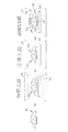
図1〜図3を参照して、実施形態に係る組立工程は、概説すれば、仮組立装置11において実施される仮組立工程と、溶接装置12において実施される溶接工程と、加熱装置13において実施される加熱工程と、を含んでいる。仮組立工程は、溶接接合する少なくとも2つの部材21、22、23を組立治具30にセットし、加熱処理によって接着力が低下して剥離可能な熱剥離型接着剤36によって仮止めして仮組立体31を形成する工程である。溶接工程は、仮組立体31を溶接治具40にセットし、部材21、22、23同士を溶接接合して接合体41を形成する工程である。加熱工程は、接合体41を加熱処理して熱剥離型接着剤36を剥離して組立体51を得る工程である。なお、本明細書において、「熱剥離型接着剤を剥離する」には、加熱処理後の接着剤を物理的に剥がし取った状態とすること、あるいは加熱処理によって接着力が低下してもはや接着剤としての機能がなくなっていることから加熱処理後の接着剤を残したままの状態にしておくことの何れの状態をも含んでいる。以下、詳述する。
With reference to FIGS. 1 to 3, the assembly process according to the embodiment is briefly described in the temporary assembly process performed in the temporary assembly apparatus 11, the welding process performed in the welding apparatus 12, and the
溶接接合する部材は、例えば、フロアメイン21、ボディサイド22、ルーフレール23などの自動車車体を構成する鋼板である。
The member to be welded is, for example, a steel plate constituting an automobile body such as the floor main 21, the
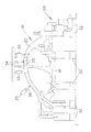
図2をも参照して、組立治具30には、部材21、22、23同士の相対位置を定めて固定する複数のクランプ装置32、33が設けられている。クランプ装置32、33には、フロアメイン21やボディサイド22用のクランプ装置32や、ルーフ用のクランプ装置33などが含まれる。図中符号34は、ルーフレール23を位置決めするためのロケート装置34を示している。図示省略するが、フロアメイン21やボディサイド22を位置決めするためのロケート装置も設けている。これらクランプ装置32、33によって部材21、22、23を組立治具30に固定した状態で、熱剥離型接着剤36によって仮止めして仮組立体31を形成する。符号35は、熱剥離型接着剤36を塗布する塗布ガンを示している。本工程においては接着が可能であればよいだけであるので、スポット溶接の作業性を考慮する必要がない。したがって、組立治具30の設計、製作を比較的短期間で容易に行うことができる。すなわち、熱剥離型接着剤36を用いて仮止めすることによって、スポット溶接の作業性を組立治具30の構造に織り込む必要が無くなり、それだけ、組立治具30を簡素な構造にすることができる。
Referring also to FIG. 2, the
熱剥離型接着剤は、熱硬化性接着剤成分に、有機系熱膨張性粒子を添加したものであり、硬化処理後、例えば70〜250℃の温度での加熱処理によって接着力が低下して剥離可能な状態となる接着剤である。この種の接着剤は、例えば特開2003−171648号に記載されているように、熱硬化性接着剤成分としては、例えば、エポキシ系樹脂、オキセタン系樹脂、反応性アクリル系樹脂、シアネートエステル系樹脂、シリコーン系樹脂、ウレタン系樹脂、ポリエステル系樹脂、シアノアクリレート系樹脂、フェノールアルデヒド系樹脂、メラミンアルデヒド系樹脂、尿素アルデヒド系樹脂、レゾルシノールアルデヒド樹脂、キシレンアルデヒド樹脂、およびフラン樹脂等の一種単独または二種以上の組み合わせが挙げられる。また、有機系熱膨張性粒子としては、マイクロカプセル内に、有機材料(ポリマー)により有機溶剤が封入された熱膨張性のマイクロカプセルを使用することができる。すなわち外殻の有機材料が加熱により軟化するとともに内殻の溶剤がガス化し、体積が、例えば5〜250倍に膨張する粒子である。より具体的には、内殻の溶剤としては、イソブタン、ペンタン、石油エーテル、ヘキサン、オクタン、イソオクタン等の有機溶剤が挙げられ、それらの有機溶剤を、外殻である塩化ビニリデン、アクリロニトリル、アクリル酸エステル、メタクリル酸エステル等からなる熱可塑性樹脂で包み込んだ熱膨張性マイクロカプセルを好ましく使用できる。本実施形態ではスポット溶接を実施するので、接着剤組成物中には、導電性を有する粒子をさらに添加している。 The heat-peelable adhesive is obtained by adding organic heat-expandable particles to a thermosetting adhesive component. After the curing treatment, the adhesive strength is reduced by heat treatment at a temperature of 70 to 250 ° C., for example. An adhesive that can be peeled off. This type of adhesive includes, for example, an epoxy resin, an oxetane resin, a reactive acrylic resin, and a cyanate ester resin as described in JP 2003-171648 A, for example. Resin, silicone resin, urethane resin, polyester resin, cyanoacrylate resin, phenol aldehyde resin, melamine aldehyde resin, urea aldehyde resin, resorcinol aldehyde resin, xylene aldehyde resin, and furan resin A combination of two or more types can be mentioned. Further, as the organic heat-expandable particles, heat-expandable microcapsules in which an organic solvent is enclosed in an organic material (polymer) in the microcapsules can be used. That is, the organic material of the outer shell is softened by heating, the solvent of the inner shell is gasified, and the volume expands, for example, 5 to 250 times. More specifically, examples of the solvent for the inner shell include organic solvents such as isobutane, pentane, petroleum ether, hexane, octane, isooctane, and the like. Thermally expandable microcapsules encapsulated with a thermoplastic resin made of ester, methacrylic acid ester or the like can be preferably used. In this embodiment, since spot welding is performed, particles having conductivity are further added to the adhesive composition.
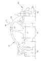
図3をも参照して、溶接治具40にも、仮組立体31を固定する複数のクランプ装置42が設けられている。クランプ装置42によって仮組立体31を溶接治具40にセットした状態で、部材21、22、23同士をスポット溶接によって接合して接合体41を形成する。仮組立体31は熱剥離型接着剤36によってすでに仮止めされている。したがって、組立治具30に設けていたルーフ用のクランプ装置33やロケート装置34などは不要であり、溶接治具40には設けていない。溶接治具40の周囲には、溶接ガン45を備えた溶接ロボットが配置されている。ルーフ用のクランプ装置等が設けられていないので、溶接ガン45の移動軌跡や姿勢の選択の自由度が非常に高い。したがって、溶接治具40の設計、製作を比較的短期間で容易に行うことができる。すなわち、熱剥離型接着剤36を用いて仮止めすることによって、スポット溶接の作業性を溶接治具40の構造に織り込む必要が無くなり、それだけ、溶接治具40を簡素な構造にすることができる。
Referring also to FIG. 3, the
図1を再び参照して、本実施形態にあっては、加熱処理を、接合体41に対して塗装を施す塗装ラインに設けられた塗装オーブン52において実施している。自動車車体を組み立てた後は一般的に塗装が施されることから、塗装オーブン52を用いることによって新たな加熱手段を設ける必要がない。塗装オーブン52によって、塗装工程における洗浄水などを蒸発させている。加熱処理は、熱剥離型接着剤36の接着力が低下して剥離可能となる温度(例えば、70〜250℃)において行う。
Referring again to FIG. 1, in the present embodiment, the heat treatment is performed in a
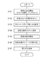
次に、図4を参照して、本実施形態の作用を説明する。 Next, the operation of the present embodiment will be described with reference to FIG.
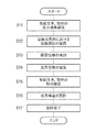
まず、組立治具30を開放する。すなわち、ロケート装置34などを解除状態とし、クランプ装置32、33をアンクランプ状態とする(ステップS1)
次に、ワークとしての溶接接合する複数の部材21、22、23を組立治具30にセットする(S2)。
First, the
Next, a plurality of
次に、熱剥離型接着剤36を予め決められた位置に塗布する(S3)。
Next, the
次に、ロケート装置34などによって部材21、22、23同士の相対位置を定め、クランプ装置32、33をクランプ状態とし、ワークを固定する(S4)。この状態で、熱剥離型接着剤が硬化するまで待機する(S5)。熱剥離型接着剤が硬化すると、複数の部材21、22、23を熱剥離型接着剤によって仮止めした仮組立体31の形成が終了する。
Next, the relative positions of the
仮組立体31の形成が終了すると、組立治具30を開放し(S6)、仮組立体31を組立治具30から取り出す(S7)。
When the formation of the
次に、仮組立体31を溶接治具40にセットし、部材21、22、23同士をスポット溶接によって接合する(S8)。これによって接合体41の形成が終了する。
Next, the
そして、接合体41に対して種々の塗装を施し、塗装オーブン52内において接合体41を加熱処理する(S9)。加熱処理によって熱剥離型接着剤の接着力が低下して剥離する。これによって、熱剥離型接着剤を剥離した組立体51の形成が終了する。
Then, various coatings are applied to the bonded
組立体51においては熱剥離型接着剤36が剥離されていることから、設計上の条件、例えば、溶接によって接合すること等の条件を簡単に満たすことができる。図面指示に合わせた接合ができるので、製品の強度・剛性が変わることがない。
Since the heat-peeling
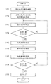
図5には、本実施形態における溶接治具40を設計する手順が示されている。
FIG. 5 shows a procedure for designing the
まず、仮組立体31および仮組立体31に溶接接合する他の部材を溶接治具40内に投入する順序を確認する(S11)。
First, the order in which the
溶接治具40内における溶接部位の位置を確認し(S12)、仮組立体31や他の部材と、これらを支持するためのポストとの間の干渉状況などを把握し、溶接治具40の大まかな構造の仕様を検討する(S13)。
The position of the welding site in the
溶接治具40の治具仕様が確定すると(S14)、仮組立体31や他の部材の形状を確認し(S15)、溶接ガン45のスイング機構などを含めた治具構造を設計する(S16)。これによって、溶接治具40の設計が完了する(S17)。
When the jig specifications of the
本実施形態では、熱剥離型接着剤36によって仮止めした仮組立体31を溶接治具40に投入するため、仮組立体31を保持する位置を、溶接ガン45の移動に干渉しない位置に簡単に設定することができる。したがって、組立治具30および溶接治具40の構造仕様の検討(S13)、および治具構造の設計(S16)を容易に行うことができ、事前検討に必要な時間や修正にかかる時間を排除することができる。また、溶接治具40の設計自由度が増しているので、溶接治具40外において増し打ち溶接を行う必要がないように、溶接治具40を設計することができる。
In this embodiment, since the
図6は、熱剥離型接着剤によって仮組立体を形成しない対比例おける、溶接接合による組立手順を示すフロー図である。 FIG. 6 is a flowchart showing an assembling procedure by welding joining in a comparative manner in which a temporary assembly is not formed by the heat-peeling adhesive.
まず、溶接治具を開放する。すなわち、ロケート装置を解除状態とし、クランプ装置をアンクランプ状態とする(ステップS101)
次に、ワークとしての溶接接合する複数の部材を溶接治具にセットする(S102)。
First, the welding jig is opened. That is, the locating device is set to the released state, and the clamping device is set to the unclamped state (step S101).
Next, a plurality of members to be welded as workpieces are set on the welding jig (S102).
次に、ロケート装置によって部材同士の相対位置を定め、クランプ装置をクランプ状態とし、ワークを固定する(S103)。 Next, the relative position between the members is determined by the locating device, the clamping device is brought into the clamping state, and the work is fixed (S103).
この状態で、部材同士をスポット溶接によって接合する(S104)。 In this state, the members are joined by spot welding (S104).
溶接治具内における溶接接合が終了すると、溶接治具を開放し(S105)、ワークを溶接治具から取り出す(S106)。そして、溶接治具外において、溶接できなかった打点について増し打ち溶接を行う(S107)。 When the welding joint in the welding jig is completed, the welding jig is released (S105), and the workpiece is taken out from the welding jig (S106). Further, outside the welding jig, additional hit welding is performed for the hit points that could not be welded (S107).
図7には、対比例における溶接治具を設計する手順が示されている。 FIG. 7 shows a procedure for designing a welding jig in a proportional manner.
まず、溶接接合する複数の部材を溶接治具内に投入する順序を確認する(S111)。 First, the order of putting a plurality of members to be welded into the welding jig is confirmed (S111).
溶接治具40内における溶接部位の位置を確認し(S112)、部材と、これらを支持するためのポストとの間の干渉状況などを把握し、溶接治具の大まかな構造の仕様を検討する(S113)。溶接ガンの移動軌跡や姿勢を加味して、溶接作業が可能か否かの確認を行う(S114)。
The position of the welding part in the
溶接作業が可能であることを確認するまで検討を繰り返し(S113、S114)、溶接治具の治具仕様が確定すると(S115)、部材の形状を確認し(S116)、溶接ガンのスイング機構などを含めた治具構造を設計する(S117)。溶接ガンの移動軌跡や姿勢を加味して、溶接作業が可能か否かの確認を行う(S118)。 The examination is repeated until it is confirmed that the welding operation is possible (S113, S114). When the jig specification of the welding jig is determined (S115), the shape of the member is confirmed (S116), the welding gun swing mechanism, etc. Is designed (S117). Considering the movement trajectory and posture of the welding gun, it is confirmed whether or not the welding operation is possible (S118).
溶接作業が可能であることを確認するまで検討を繰り返し(S117、S118)、溶接作業が可能であることを確認できれば、溶接治具の設計が完了する(S119)。 The examination is repeated until it is confirmed that the welding work is possible (S117, S118). If it can be confirmed that the welding work is possible, the design of the welding jig is completed (S119).
対比例では、部材の保持と溶接ガンの移動との両立を図りつつ溶接治具の設計をしなければならないため、溶接治具の構造仕様の検討(S113、S114)、および治具構造の設計(S117、S118)が煩雑であり、溶接治具の設計、製作に比較的長期間を要する。 In contrast, the welding jig must be designed while achieving both the holding of the member and the movement of the welding gun, so the examination of the structural specifications of the welding jig (S113, S114) and the design of the jig structure (S117, S118) is complicated, and it takes a relatively long time to design and manufacture the welding jig.
これに対して本実施形態にあっては、上述したように、熱剥離型接着剤36によって仮止めした仮組立体31を溶接治具40に投入するため、仮組立体31を保持する位置を、溶接ガン45の移動に干渉しない位置に簡単に設定することができる。したがって、溶接治具40の構造仕様の検討(S13)、および治具構造の設計(S16)を容易に行うことができる。
On the other hand, in the present embodiment, as described above, the
さらに、組立体51においては熱剥離型接着剤36が剥離されていることから、設計上の条件、例えば、溶接によって接合すること等の条件を簡単に満たすことができる。図面指示に合わせた接合ができるので、製品の強度・剛性が変わることがない。
Furthermore, since the heat-peeling
したがって、本実施形態の組み立て手法によれば、コストを抑えた簡便な組み立て手法であって、かつ、設計上の条件を満足し得る溶接接合による組立手法となる。本実施形態の組み立て手法は、特に、試作段階や少量生産の場合などに有効な手段となる。 Therefore, according to the assembling method of the present embodiment, it is a simple assembling method with reduced cost and an assembling method by welding joining that can satisfy the design condition. The assembly method according to the present embodiment is an effective means particularly in the trial production stage and in the case of small-scale production.
部材21、22、23が自動車車体を構成する鋼板であるので、コストを抑えた簡便な組み立て手法で、かつ、設計上の条件を満足した溶接接合による組立手法によって、自動車車体を組み立てることができる。特に、自動車車体の試作段階や少量生産の場合などに有効な手段となる。
Since the
加熱処理を、接合体41に対して塗装を施す塗装ラインに設けられた塗装オーブン52において実施するので、新たな加熱手段を設ける必要がなく、コストをさらに抑えることができる。
Since the heat treatment is performed in the
(変形例)
溶接接合する部材21、22、23として自動車車体を構成する鋼板を例に挙げたが、本発明はこの場合に限定されるものではなく、溶接接合する少なくとも2つの部材を組み立てる方法に広く適用することができる。
(Modification)
The steel plates constituting the automobile body are exemplified as the
また、加熱処理を塗装オーブン52において行う場合に限定されるものでもない。専用の加熱機などを設けても何ら支障はない。
Further, the present invention is not limited to the case where the heat treatment is performed in the
21、22、23 溶接接合する部材、
30 組立治具、
31 仮組立体、
36 熱剥離型接着剤、
40 溶接治具、
41 接合体、
51 組立体、
52 塗装オーブン。
21, 22, 23 members to be welded,
30 assembly jig,
31 Temporary assembly,
36 heat release adhesive,
40 welding jig,
41 joined body,
51 assembly,
52 Painting oven.
Claims (3)
前記仮組立体を溶接治具にセットし、前記部材同士を溶接接合して接合体を形成する工程と、
前記接合体を加熱処理して前記熱剥離型接着剤を剥離して組立体を得る工程と、を有する溶接接合による組立方法。 Setting at least two members to be welded together in an assembly jig, forming a temporary assembly by temporarily fixing with a heat-peelable adhesive that can be peeled off due to a decrease in adhesive force by heat treatment;
Setting the temporary assembly on a welding jig and welding the members together to form a joined body;
And a step of heat-treating the joined body to peel off the heat-peeling adhesive to obtain an assembly.
Priority Applications (1)
| Application Number | Priority Date | Filing Date | Title |
|---|---|---|---|
| JP2010168566A JP2012024908A (en) | 2010-07-27 | 2010-07-27 | Assembling method by weld-bonding |
Applications Claiming Priority (1)
| Application Number | Priority Date | Filing Date | Title |
|---|---|---|---|
| JP2010168566A JP2012024908A (en) | 2010-07-27 | 2010-07-27 | Assembling method by weld-bonding |
Publications (1)
| Publication Number | Publication Date |
|---|---|
| JP2012024908A true JP2012024908A (en) | 2012-02-09 |
Family
ID=45778471
Family Applications (1)
| Application Number | Title | Priority Date | Filing Date |
|---|---|---|---|
| JP2010168566A Pending JP2012024908A (en) | 2010-07-27 | 2010-07-27 | Assembling method by weld-bonding |
Country Status (1)
| Country | Link |
|---|---|
| JP (1) | JP2012024908A (en) |
Cited By (1)
| Publication number | Priority date | Publication date | Assignee | Title |
|---|---|---|---|---|
| CN115279653A (en) * | 2020-03-27 | 2022-11-01 | 本田技研工业株式会社 | Vehicle body assembling device and vehicle body assembling method |
-
2010
- 2010-07-27 JP JP2010168566A patent/JP2012024908A/en active Pending
Cited By (1)
| Publication number | Priority date | Publication date | Assignee | Title |
|---|---|---|---|---|
| CN115279653A (en) * | 2020-03-27 | 2022-11-01 | 本田技研工业株式会社 | Vehicle body assembling device and vehicle body assembling method |
Similar Documents
| Publication | Publication Date | Title |
|---|---|---|
| US10442243B2 (en) | Method for producing a wheel rim with a rim base of fiber composite material | |
| US20150336271A1 (en) | System and method for fixtureless component location in assembling components | |
| EP1975216B1 (en) | Joining structure and method of metal works | |
| CN103261005A (en) | Method for establishing an adhesive connection between at least two components, in particular vehicle body components, by means of positive-fit elements | |
| US20100192377A1 (en) | Method for producing a fuselage airframe of an aircraft | |
| JP5985582B2 (en) | Assembly method for vehicle bonnet | |
| US20170334168A1 (en) | Hybrid Adhesive System For Metal and Composite Assemblies | |
| JP2018507357A (en) | Bonding component and manufacturing method thereof | |
| US20160039168A1 (en) | Design and processes for making light, stiff and strong structures | |
| JP2012024908A (en) | Assembling method by weld-bonding | |
| JP6272337B2 (en) | Joined parts, composite joined parts and manufacturing method thereof | |
| KR20160082288A (en) | fastener for joining sheet | |
| JP2018091486A (en) | Fastener and method of producing the same | |
| JP2008296556A (en) | Adhesive bonding member and method for manufacturing the member | |
| JP2009242465A (en) | Method for manufacturing bond assembly, and apparatus for manufacturing bond assembly | |
| US20160039193A1 (en) | Process for securing a micro-truss structure to a panel | |
| EP2006339A1 (en) | Joining method of works | |
| KR20120050213A (en) | Welding method for steel sheets | |
| JP2006308088A (en) | Joint improvements | |
| JP4193663B2 (en) | Method of joining metal members | |
| JP2019069534A (en) | Metal resin joint method | |
| US20180169961A1 (en) | System and method for bonding structures | |
| JP5375008B2 (en) | Adhesive bonding method | |
| JP5353819B2 (en) | Steel welded joint structure | |
| JP2018520875A (en) | Joining component and joining method |