JP2012017735A - Fluid power generation device - Google Patents
Fluid power generation device Download PDFInfo
- Publication number
- JP2012017735A JP2012017735A JP2011124259A JP2011124259A JP2012017735A JP 2012017735 A JP2012017735 A JP 2012017735A JP 2011124259 A JP2011124259 A JP 2011124259A JP 2011124259 A JP2011124259 A JP 2011124259A JP 2012017735 A JP2012017735 A JP 2012017735A
- Authority
- JP
- Japan
- Prior art keywords
- housing
- generator
- rotating shaft
- bearing
- power generation
- Prior art date
- Legal status (The legal status is an assumption and is not a legal conclusion. Google has not performed a legal analysis and makes no representation as to the accuracy of the status listed.)
- Granted
Links
- 239000012530 fluid Substances 0.000 title claims abstract description 28
- 238000010248 power generation Methods 0.000 title claims abstract description 20
- 230000005540 biological transmission Effects 0.000 claims abstract description 37
- 230000007246 mechanism Effects 0.000 claims description 35
- 239000010687 lubricating oil Substances 0.000 claims description 26
- 238000013016 damping Methods 0.000 claims description 13
- 238000007789 sealing Methods 0.000 claims description 4
- 230000008859 change Effects 0.000 claims description 3
- 230000004044 response Effects 0.000 claims description 2
- 239000003921 oil Substances 0.000 description 8
- 238000004891 communication Methods 0.000 description 6
- 239000002184 metal Substances 0.000 description 5
- 230000002093 peripheral effect Effects 0.000 description 3
- 239000000843 powder Substances 0.000 description 3
- 230000009471 action Effects 0.000 description 2
- 230000005484 gravity Effects 0.000 description 2
- 238000004519 manufacturing process Methods 0.000 description 2
- 230000001629 suppression Effects 0.000 description 2
- 238000005452 bending Methods 0.000 description 1
- 239000000470 constituent Substances 0.000 description 1
- 230000007423 decrease Effects 0.000 description 1
- 230000000694 effects Effects 0.000 description 1
- 230000005611 electricity Effects 0.000 description 1
- 230000005674 electromagnetic induction Effects 0.000 description 1
- 238000009434 installation Methods 0.000 description 1
- 238000012986 modification Methods 0.000 description 1
- 230000004048 modification Effects 0.000 description 1
- 230000000087 stabilizing effect Effects 0.000 description 1
- 239000000126 substance Substances 0.000 description 1
Images


Classifications
-
- Y—GENERAL TAGGING OF NEW TECHNOLOGICAL DEVELOPMENTS; GENERAL TAGGING OF CROSS-SECTIONAL TECHNOLOGIES SPANNING OVER SEVERAL SECTIONS OF THE IPC; TECHNICAL SUBJECTS COVERED BY FORMER USPC CROSS-REFERENCE ART COLLECTIONS [XRACs] AND DIGESTS
- Y02—TECHNOLOGIES OR APPLICATIONS FOR MITIGATION OR ADAPTATION AGAINST CLIMATE CHANGE
- Y02E—REDUCTION OF GREENHOUSE GAS [GHG] EMISSIONS, RELATED TO ENERGY GENERATION, TRANSMISSION OR DISTRIBUTION
- Y02E10/00—Energy generation through renewable energy sources
- Y02E10/70—Wind energy
- Y02E10/72—Wind turbines with rotation axis in wind direction
Abstract
Description
本発明は、流体発電装置に関する。特に、風力発電装置に関する。 The present invention relates to a fluid power generation apparatus. In particular, it relates to a wind power generator.
流体の流れを利用して発電を行う流体発電装置の一例として、風力発電装置(風力発電機)が知られている。風力発電装置は、周知のように、風車(羽根車)が流体の流動を受けて、生じた回転力(機械エネルギー)を発電機で電気エネルギーに変換して発電を行うものが一般的である。 A wind power generator (wind generator) is known as an example of a fluid power generator that generates power using a fluid flow. As is well known, the wind power generator generally generates power by converting the generated rotational force (mechanical energy) into electrical energy by a generator when the windmill (impeller) receives fluid flow. .
こうした流体発電装置は、風向きに応じて風車の向きを適切に変化させるために、例えば、支柱の一端に軸周方向に回動自在に形成された基台(ナセル)を備えている。そして、この基台に対して、風車の回転軸を支持する軸受、および風車の回転軸の回転数を増加させる変速機が、それぞれ個別に取り付けられている。これら軸受、および変速機は、基台に対してそれぞれ軸受、ダンパーなどの制振部材を介して接続されているのが一般的である(例えば、特許文献1参照)。 In order to appropriately change the direction of the wind turbine according to the wind direction, such a fluid power generation apparatus includes, for example, a base (nacelle) that is formed at one end of the support so as to be rotatable in the axial circumferential direction. And the bearing which supports the rotating shaft of a windmill, and the transmission which increases the rotation speed of the rotating shaft of a windmill are each attached to this base individually. These bearings and the transmission are generally connected to the base via vibration damping members such as bearings and dampers (see, for example, Patent Document 1).
しかしながら、上述した特許文献1にあるような風力発電装置では、風車の軸受と発電機とがそれぞれ個別に基台となるハウジングに対して支持され、しかも変速機とハウジングとの間には制振部材が配されているため、風車と発電機、及び増速機との間で回転力を伝達する回転軸が湾曲し、トルクが増大して磨耗が加速するなどの課題があった。
However, in the wind turbine generator as described in
また、流体発電装置の組立時においても、風車の軸受が3つ以上あるとも不静定な支持状態となるため、回転軸の軸合わせのための隙間調整が必要であり、非常に手間が掛かるという課題があった。 Also, when assembling the hydroelectric generator, even if there are three or more wind turbine bearings, it becomes an indefinite support state, so it is necessary to adjust the clearance for the alignment of the rotating shaft, which is very laborious. There was a problem.
本発明は、上述した事情に鑑みてなされたもので、羽根車、変速機、および発電機を連結する回転軸の撓みを防ぐことによって、回転軸の損傷や磨耗を防止、軽減できる流体発電装置を提案することを目的とする。 The present invention has been made in view of the above-described circumstances, and is a fluid power generation apparatus that can prevent or reduce damage and wear of a rotating shaft by preventing bending of the rotating shaft connecting an impeller, a transmission, and a generator. The purpose is to propose.
本発明は、流体発電装置の組立時において、回転軸の軸合わせを容易にして組立時の組立容易性を向上させた流体発電装置を提案することを目的とする。 It is an object of the present invention to propose a fluid power generation apparatus that facilitates the axial alignment of the rotating shaft during assembly of the fluid power generation apparatus and improves the ease of assembly during assembly.
本発明は、風車に連結される回転軸の回転トルクの増大を回避できる流体発電装置を提案することを目的とする。 An object of the present invention is to propose a fluid power generation apparatus capable of avoiding an increase in rotational torque of a rotating shaft connected to a windmill.
本発明は、上記課題を解決するために以下の手段を採用した。
本発明に係る流体発電装置は、流体の流動を受けて第一回転軸を中心に回転する羽根車と、前記第一回転軸の回転数を変化させて第二回転軸に伝達する変速機と、前記第二回転軸の回転力によって電力を発電する発電機と、前記第一回転軸を回転自在に支持する軸受と、支柱の一端に該支柱の中心軸を回転中心として、回転自在に支持された基台と、を備え、少なくとも前記変速機および前記軸受はハウジングに覆われ、前記ハウジングは前記基台に支持されることを特徴とする。
The present invention employs the following means in order to solve the above problems.
The fluid power generation device according to the present invention includes an impeller that rotates around a first rotation shaft in response to a fluid flow, a transmission that changes the number of rotations of the first rotation shaft, and transmits the rotation to the second rotation shaft. A generator that generates electric power by the rotational force of the second rotating shaft, a bearing that rotatably supports the first rotating shaft, and a shaft that is rotatably supported at one end of the column with the center axis of the column as a rotation center And at least the transmission and the bearing are covered with a housing, and the housing is supported by the base.
本発明によれば、羽根車および発電機をハウジングだけに支持させ、このハウジングを基台に支持させることによって、羽根車と変速機との位置関係、および変速機と発電機との位置関係は、風力発電装置の揺動や振動によっても変わることが無い。このため、羽根車と変速機とを連結する第一回転軸や、変速機と発電機とを連結する第二回転軸に応力が加わって撓んだりすることが無く、第一回転軸や第二回転軸の磨耗を抑制して、長寿命化を図ることができる。 According to the present invention, by supporting the impeller and the generator only on the housing and supporting the housing on the base, the positional relationship between the impeller and the transmission and the positional relationship between the transmission and the generator are The wind power generator does not change even when the wind power generator swings or vibrates. For this reason, the first rotary shaft that connects the impeller and the transmission and the second rotary shaft that connects the transmission and the generator are not bent due to stress, and the first rotary shaft and the first It is possible to extend the service life by suppressing the wear of the two rotating shafts.
以下、本発明の実施形態について図面を参照して説明する。
図1は、本発明の本発明の第一実施形態に係る風力発電装置10を示す外観図である。図2は、図1に示す風力発電装置10を鉛直方向における上から見たときの断面図(図1のA−A線の断面図)。
Embodiments of the present invention will be described below with reference to the drawings.
FIG. 1 is an external view showing a
水平軸型の風力発電装置(流体発電装置)10は、風車(羽根車)23の回転中心となる第一回転軸(回転主軸)21が地面(設置面)Fに対して略水平となるように設置される。つまり、風車23の第一回転軸21は、地面Fに沿って流れる風(流体)Wに沿って延びる。
In the horizontal axis type wind power generator (fluid power generator) 10, the first rotating shaft (rotating main shaft) 21 that is the rotation center of the windmill (impeller) 23 is substantially horizontal with respect to the ground (installation surface) F. Installed. That is, the first
この風力発電装置10は、地面Fに対して鉛直方向に立つように固定された支柱11と、この支柱11の一端に形成された基台(ナセル)12と、この基台12上に制振部材26を介して設置された本体部13とを備えている。基台12は回転台14を介して支柱11に接続されている。これによって、基台12は、地面Fに固定された支柱11に対して、水平面に沿って回転自在にされている。
The
本体部13は、第一回転軸21を中心に回転する風車23と、第一回転軸21の回転数を変化させて第二回転軸22に伝達する変速機24と、第二回転軸22の回転力によって電力を発電する発電機25とを備えている。なお、本体部13は全体が外装体(ケース)29で覆われていれば良い。
The
第一回転軸21の一端側には、風車23が設けられている。即ち、第一回転軸21の一端には、羽根固定部材41が固定され、この羽根固定部材41に互いに等間隔で3枚の翼ブレード(羽根)42が取り付けられている。各翼ブレード42は、風Wを受けると揚力を発生する形状に成形されている。各翼ブレード42に発生する揚力は、第一回転軸21の半径方向に対して交差する方向に発生するため、この揚力によって風車23が風(流体)Wを受け止めると第一回転軸21が回転される。
A
風車23は、回転中心である第一回転軸21の軸線S1が水平方向Rに対して角度θで僅かに傾斜していればよい。例えば、第一回転軸21の軸線S1は、水平方向Rに対して角度θが1〜3°程度上向きになるように傾斜して形成されていればよい。これによって、風車23を構成する翼ブレード(羽根)42が強風などによって撓んだとしても、支柱11に接触することを防止できる
The
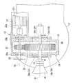
図3は、本体部13の概略構成を示す拡大断面図(図1のA−A線の断面図)である。
変速機24は、外部が例えば金属からなるハウジング31で覆われている。このハウジング31は、制振部材26(図1も参照)を介して基台12に支持される。制振部材26は、例えば制振ゴム、またはバネ、オイルダンパーなどの弾性体から構成されていれば良い。こうした制振部材26は、例えば、強風などによってハウジング31を含む本体部13に生じた振動、揺動などを吸収し、本体部13が基台12上で大きく振動することを防止する。
FIG. 3 is an enlarged cross-sectional view (cross-sectional view taken along line AA in FIG. 1) showing a schematic configuration of the
The
ハウジング31には、第一回転軸21および第二回転軸22が回転自在に支持されている。第一回転軸21には、ハウジング31内において第一歯車32が固定されている。第一回転軸21は、この第一歯車32を挟んで前後に配された第一軸受34aと第二軸受34bとからなる一対の軸受34によって、ハウジング31に対して回転自在に支持されている。
A first rotating
軸受34のうち、第一軸受34aは、第一回転軸21の円周方向の応力を受け止めるラジアル軸受と第一回転軸21の軸方向の応力を受け止めるスラスト軸受の機能を有する。
また、第二軸受34bは、第一回転軸21の円周方向の応力を受け止めるラジアル軸受である。
Of the
The second bearing 34 b is a radial bearing that receives stress in the circumferential direction of the first rotating
第二回転軸22には、ハウジング31内において第二歯車33が固定されている。第二回転軸22は、この第二歯車33を挟んで前後に配された第三軸受35aと第四軸受35bとからなる一対の軸受35によって、ハウジング31に対して回転自在に支持されている。そして、第二歯車33は、第一歯車32と噛み合う様に形成されており、第一回転軸21が回転すると、第一歯車32および第二歯車33を介して第二回転軸22が回転される。
A second gear 33 is fixed to the second rotating
第二歯車33は、第一歯車32よりも小径のものが用いられれば良い。これによって、第一回転軸(低速軸)21の回転は、変速機24によって増速され、第一回転軸(低速軸)21の回転数よりも大きい回転数で第二回転軸(高速軸)22が回転される。
The second gear 33 may have a smaller diameter than the
第二回転軸22の一端には、発電機25の回転軸25aが接続されている。発電機25は、例えばオルタネーターなどの交流発電機であればよい。こうした発電機25は、第二回転軸22の回転によって回転されるマグネットロータと、このマグネットロータの外周側を取り囲むように配置されたコイルステータとから構成され、マグネットロータの回転によってコイルステータとの間で、電磁誘導が発生して発電が行われる。なお、発電機25で発電された電力は、不図示の整流回路を介してバッテリに充電されればよい。
One end of the second rotating
発電機25は、発電機支持部材27に固定されている。そして、この発電機支持部材27は、変速機24のハウジング31に固定される。即ち、発電機25は、発電機支持部材27を介してハウジング31に固定されている。
The
このような構成の風力発電装置10の発電動作について説明する。風力発電装置10の風車23が風(流体)Wを受けると、本体部13を支持する基台(ナセル)12は、回転台14によって、風車23の回転面が風Wに正対するように回転する。そして、風Wによって風車23が回転を始める。
The power generation operation of the
風車23が回転すると、この風車23が固定されている第一回転軸21が回転する。第一回転軸21の回転によって、変速機24を構成する第一歯車32が回転する。この第一歯車32が回転によって、第一歯車32と噛み合う第二歯車33が回転する。
When the
この時、第二歯車33は、第一歯車32よりも小径であるので、第一回転軸21の回転数が増加(増速)されて第二回転軸22が回転する。風車23の回転数は比較的低速であり、効率よく発電を行うために変速機24によって回転数を増加させる。
At this time, since the second gear 33 has a smaller diameter than the
第二回転軸22が回転すると、この第二回転軸22に接続されている発電機25の回転軸25aが回転されて、発電機25で発電を行うことができる。
When the second
以上のような風力発電装置10の作用、効果を説明する。
本発明の風力発電装置10は、変速機24のハウジング31に、第一回転軸21を回転自在に支持する第一軸受34a、第二軸受34bが設けられている。即ち、ハウジング31に風車23が支持されている。発電機25も、発電機支持部材27を介してハウジング31に支持されている。
The operation and effect of the
In the
そして、これら風車23および発電機25を支持した(一体化した)ハウジング31が、基台12に支持される構造を成している。
本発明によれば、これによって、強風や振動を受けても第一回転軸21や第二回転軸22がズレたり撓んだりすることを防止できる。
即ち、従来の風力発電装置は、風車、変速機、発電機などが個々に独立して制振部材等を介して基台(ナセル)に支持されている構成であったため、それぞれの構成部材どうしの位置が振動などで動いたりすると、風車と変速機とを連結する回転軸や、変速機と発電機とを連結する回転軸が撓むなどして、風車と発電機、および変速機との間で、回転軸の磨耗が加速する原因となっていた。
A
According to the present invention, this makes it possible to prevent the first
In other words, the conventional wind power generator has a configuration in which the wind turbine, the transmission, the generator, and the like are individually supported by the base (nacelle) via the damping member and the like. If the position of the wind turbine moves due to vibration or the like, the rotating shaft that connects the windmill and the transmission or the rotating shaft that connects the transmission and the generator is bent. In the meantime, the wear of the rotating shaft accelerated.
本発明では、風車23および発電機25をハウジング31だけに支持させ、このハウジング31を基台12に支持させることによって、風車23と変速機24との位置関係、および変速機24と発電機25との位置関係は、風力発電装置10の揺動や振動によっても変わることが無い。
In the present invention, the
そして、第一回転軸21だけでなく、第二回転軸22も第三軸受35aと第四軸受35bとからなる一対の軸受35によって支持されることで、不静定な状態となることが防止できる。これにより、第一回転軸21や第二回転軸22の湾曲が防止され、第一回転軸21や第二回転軸22の磨耗を抑制して長寿命化を図ることが可能になる。
And not only the 1st
風力発電装置10は、製造時においても、変速機24や風車23の第一回転軸21を、それぞれ個別に制振部材を介して基台12に設けるのではなく、ハウジング31に一括して固定させるので、取付位置の位置決めが容易であり、第一回転軸21や第二回転軸22の軸線が曲がったりすることなく、確実に所定位置にズレなく取り付けることが可能になる。これによって、風力発電装置10の製造時においては、組立性を向上させることができる。また、風力発電装置10の動作時においては、第一回転軸21や第二回転軸22に内部荷重が生じて損傷することを確実に防止できる。
In the
また、ハウジング31と基台12との間に制振部材26を設けることによって、風車23および発電機25を含む本体部13の全体に振動や揺動が発生することを防止できる。
In addition, by providing the damping
更に、風車23が一端に固定される第一回転軸21を、第一軸受34aと第二軸受34bの2つの軸受34でハウジング31に支持させることによって、風車23をハウジング31に対して安定して回転自在に支持させることができる。
Further, the first
更に、図3に示すように、第一回転軸21の軸線S1と、第二回転軸22の軸線S2とが、互いに異なる位置に沿って延びるように、第一回転軸21と第二回転軸22とをずらして配置したので、変速機24の小型化にも寄与する。
Further, as shown in FIG. 3, the first
なお、第一実施形態では、第一回転軸21と第二回転軸22とを水平方向にずらして配置しているが、これ以外にも、例えば、第一回転軸21と第二回転軸22とを鉛直方向に沿って上下に配置しても良い。第一回転軸(低速軸)21と第二回転軸(高速軸)22とを上下方向にずらして配置すれば、風力発電装置10の本体部13の水平方向における重量バランスが向上し、より一層安定して発電を行うことができる。
In the first embodiment, the first
図4は、本発明の第二実施形態に係る風力発電装置50を示す要部拡大断面図である。
風力発電装置50では、一端に風車が固定される第一回転軸61の軸線と、一端に発電機の回転軸と接続される第二回転軸62の軸線とが同一の軸線S3上に位置するように構成した。
FIG. 4 is an enlarged cross-sectional view showing a main part of a
In the wind
変速機54は、外部が例えば金属からなるハウジング51で覆われ、このハウジング51は、制振部材56を介して基台12(図1参照)に支持される。ハウジング51には、第一回転軸61、第二回転軸62、およびこの2つの回転軸を連動させる連結回転軸63がそれぞれ回転自在に支持されている。
The exterior of the
第一回転軸61には、ハウジング51内において第一歯車72が固定されている。また、第二回転軸62には、第二歯車73が固定されている。そして、連結回転軸63には、第一歯車72の回転を第二歯車73に伝える2つの従動歯車74a,74bが固定されている。
A
こうした構成によって、風車(図1参照)の回転によって第一回転軸61が回転すると、第一歯車72から従動歯車74a,74bを介して第二歯車73に回転力が伝えられる。そして、第二歯車73が一端に固定されている第二回転軸62が回転することにより、第二回転軸62に接続された発電機65の回転軸66が回転され、発電が行われる。
With this configuration, when the first
風力発電装置50においても、発電機65を支持する発電機支持部材67は、ハウジング51に固定されている。また、風車もハウジング51に形成された軸受に支持されている。即ち、風車および発電機65はハウジング51だけに支持される。
Also in the
第二実施形態においても、強風や振動を受けても風車と変速機54とを連結する第一回転軸61や、変速機54と発電機65とを連結する第二回転軸62が撓んだりすることが無い。その結果、風力発電装置50の制振部材56が揺動しても、風車と変速機54との位置ズレ、変速機54と発電機65との位置ズレによる第一回転軸61や、第二回転軸62の磨耗を防止して、長寿命化を図ることが可能になる。
Also in the second embodiment, the first
また、一端に風車が固定される第一回転軸61の軸線と、一端に発電機の回転軸と接続される第二回転軸62の軸線とを同一の軸線S3上に位置するように構成することで、風力発電装置50の風の流れる方向に直交する幅方向のサイズを小さくすることができ、より一層、風力発電装置50の小型化を実現できる。
In addition, the axis of the first
図5は、図3のB―B線の断面図である。
図3では図示を省略していたが、第一実施形態に係る風力発電装置10のハウジング31には、第一軸受34a及び第二軸受34bの外部側に、シール機構80が設けられている。
シール機構80は、ハウジング31の内部に異物が侵入することを防止するため、またハウジング31の内部の潤滑油Lが漏出するのを防止するために設けられる。
5 is a cross-sectional view taken along line BB in FIG.
Although not shown in FIG. 3, a
The
シール機構80としては、非接触型シール機構であるラビリンスシール機構が採用される。
例えばオイルシール等の接触型シール機構を用いた場合には、第一回転軸21に摺動抵抗(摺動摩擦)が与えられて、第一回転軸21の回転を阻害してしまう。つまり、第一回転軸21に動力損失が発生して、風力発電装置50の発電効率が低下する。
このため、上述したように、風力発電装置50では、非接触型シール機構(ラビリンスシール機構)であるシール機構80を採用して、第一回転軸21の回転トルクの増大を回避している。シール機構80を用いた場合には、接触型シール機構の場合と比べて、第一回転軸21の回転トルクを10%以上低減することができる。
As the
For example, when a contact-type sealing mechanism such as an oil seal is used, sliding resistance (sliding friction) is applied to the first
Therefore, as described above, the
シール機構80は、第一回転軸21を挿通するためにハウジング31に形成された孔部に取り付けられるリング部81と、第一回転軸21に嵌め込まれたフランジ部82とから構成される。そして、リング部81の内周側の段差とフランジ部82の外周側の段差とを第一回転軸21の軸方向において近接させることによりラビリンスが形成される。なお、ラビリンスシール機構の段数は、任意に設定することができる。
シール機構80は、変速機24や軸受34等が収容されるハウジング31に設けられるため、部品点数を最小限に抑えることができる。すなわち、変速機24や軸受34に対して別々にシール機構を設ける必要がないので、最小限の部品点数に抑えられる。
The
Since the
第一回転軸21の軸線S1は、水平方向Rに対して角度θで僅かに傾斜している。例えば、角度θは、1〜3°程度上向きに設定される。このため、ハウジング31の内部の貯留された潤滑油Lは、第一回転軸21を伝わって、下方側の第二軸受34bの周辺に溜まりやすい。
しかし、シール機構80は、非接触型(ラビリンスシール機構)であるため、潤滑油Lの漏出を完全に防止できない。そこで、第二軸受34bの軸方向下方側に潤滑油循環機構90を設ける。具体的には、ハウジング31に取り付けられたリング部81にオイル溜まり91を形成し、このオイル溜まり91とハウジング31の底側内部空間31Sを連通管92により連結する。これにより、第二軸受34bの軸方向下方側に流れ込んだ潤滑油Lは、一旦、リング部81のオイル溜まり91に集められ、その後、重力の作用により連通管92を介してハウジング31の底側内部空間31Sに向けて戻される。このため、ハウジング31の内部の潤滑油Lが漏出するのを防止することができる。
The axis S1 of the first
However, since the
潤滑油Lは、ハウジング31が1〜3°程度の傾斜(角度θ)を有して設置されているので、ポンプ等の動力源を用いることなく、底側内部空間31Sと潤滑油循環機構90の間を自然(自動)に循環する。
すなわち、ハウジング31の底側内部空間31Sに収容された潤滑油Lは、風車23の回転に連動する変速機24(第一歯車32)によってハウジング31の内部で拡散される。第一回転軸21に付着した潤滑油Lは、第一回転軸21が傾斜(角度θ)しているため、
第一回転軸21に沿って下方に流れ、第二軸受34bを通過して潤滑油循環機構90のオイル溜まり91に達する。そして、上述したように、オイル溜まり91に流れ込んだ潤滑油Lは、重力の作用により連通管92を介してハウジング31の底側内部空間31Sに向けて戻される。
このようにして、ハウジング31の内部の潤滑油Lを自然(自動)循環させることができる。
そこで、潤滑油循環機構90の連通管92の一部に、金属粉などを除去するフィルタ(不図示)を設けてもよい。ハウジング31の内部空間Sと連通管92の間で、潤滑油Lが循環するので、金属粉などの異物をフィルタにより効率的に除去することが可能となる。
Since the
That is, the lubricating oil L accommodated in the bottom inner space 31S of the
The oil flows downward along the first
In this way, the lubricating oil L inside the
Therefore, a filter (not shown) for removing metal powder or the like may be provided in a part of the
なお、潤滑油循環機構90は、第二軸受34bの近傍に設ける場合に限らない。第一軸受34aの近傍にも設けてもよい。
また、第二回転軸22を支持する軸受35の近傍に、シール機構80及び潤滑油循環機構90を設けてもよい。
The lubricating
Further, a
このように、風力発電装置10は、第一回転軸21が接続されるハウジング31に非接触型のシール機構80を設けたので、第一回転軸21の回転トルクの増大を回避できる。また、シール機構80の部品点数を最小限に抑えることができる。
Thus, since the
また、第二軸受34bの軸方向下方側に、潤滑油Lをハウジング31の底側内部空間31Sに戻す潤滑油循環機構90を設けたので、潤滑油Lが漏出を確実に防止できる。潤滑油循環機構90の連通管92にフィルタを設けることにより、潤滑油Lに含まれる金属粉などの異物を効率的に除去することができる。
なお、第二実施形態に係る風力発電装置50においても、シール機構80及び潤滑油循環機構90を用いることができる。
Further, since the lubricating
In the
なお、上述した各実施形態において示した各構成部材の諸形状や組み合わせ等は一例であって、本発明の主旨から逸脱しない範囲において設計要求等に基づき種々変更可能である。 Note that the shapes, combinations, and the like of the constituent members shown in the above-described embodiments are merely examples, and various modifications can be made based on design requirements and the like without departing from the gist of the present invention.
例えば、上述した各実施形態では、発電機を発電機支持部材を介してハウジングに固定したが、発電機をハウジングに直接固定する構成であっても良い。また、上述した各実施形態では、ハウジングと基台とは、制振部材を介して接続しているが、ハウジングを基台に直接接続してもよい。 For example, in each of the embodiments described above, the generator is fixed to the housing via the generator support member. However, the generator may be directly fixed to the housing. Moreover, in each embodiment mentioned above, although the housing and the base are connected via the damping member, you may connect a housing directly to a base.
上述した各実施形態では、第一軸受34aが複列(ラジアル軸受とスラストラジアル軸受)であり、第二軸受34bが単列(ラジアル軸受)であるの場合について説明したが、これに限らない。第一軸受34aを単列(ラジアル軸受)、第二軸受34bを複列(ラジアル軸受とスラスト軸受)にしてもよい。
In each of the above-described embodiments, the case where the
なお、上述した各実施形態では、羽根車を回転させる流体として、風を挙げているが、風力に限らず、水力であってもよい。つまり、本発明は、水力発電装置に適用することができる。 In each embodiment mentioned above, although wind is mentioned as fluid which rotates an impeller, it may be not only wind power but hydraulic power. That is, the present invention can be applied to a hydroelectric generator.
10,50…風力発電装置(流体発電装置)、 12…基台(ナセル)、 21,61…第一回転軸、 22,62…第二回転軸、 23…風車(羽根車)、 24,54…変速機、 25,65…発電機、 26,56…制振部材、 31,51…ハウジング、 31S…底側内部空間、 34…軸受、 34a…第一軸受、 34b…第二軸受、 80…シール機構、 90…潤滑油循環機構、 W…風(流体)、 S1−S3…軸線
DESCRIPTION OF
Claims (7)
前記第一回転軸の回転数を変化させて第二回転軸に伝達する変速機と、
前記第二回転軸の回転力によって電力を発電する発電機と、
前記第一回転軸を回転自在に支持する軸受と、
支柱の一端に該支柱の中心軸を回転中心として、回転自在に支持された基台と、を備え、
少なくとも前記変速機および前記軸受はハウジングに覆われ、
前記ハウジングは前記基台に支持されることを特徴とする流体発電装置。 An impeller that rotates around the first rotation axis in response to fluid flow;
A transmission that changes the number of rotations of the first rotation shaft and transmits the change to the second rotation shaft;
A generator for generating electric power by the rotational force of the second rotary shaft;
A bearing that rotatably supports the first rotating shaft;
A base that is rotatably supported around the center axis of the support at one end of the support,
At least the transmission and the bearing are covered by a housing;
The fluid power generation apparatus according to claim 1, wherein the housing is supported by the base.
前記非接触型シール機構の近傍に溜まる潤滑油を前記ハウジングの底側内部空間に戻す潤滑油循環機構と、
を備えることを特徴とする請求項1から請求項6のうちいずれか一項に記載の流体発電装置。 A non-contact type sealing mechanism provided between the housing and the first rotating shaft;
A lubricating oil circulation mechanism that returns lubricating oil accumulated in the vicinity of the non-contact type sealing mechanism to the inner space on the bottom side of the housing;
The fluid power generation device according to any one of claims 1 to 6, further comprising:
Priority Applications (1)
| Application Number | Priority Date | Filing Date | Title |
|---|---|---|---|
| JP2011124259A JP6049985B2 (en) | 2010-06-11 | 2011-06-02 | Fluid power generator |
Applications Claiming Priority (3)
| Application Number | Priority Date | Filing Date | Title |
|---|---|---|---|
| JP2010134262 | 2010-06-11 | ||
| JP2010134262 | 2010-06-11 | ||
| JP2011124259A JP6049985B2 (en) | 2010-06-11 | 2011-06-02 | Fluid power generator |
Publications (2)
| Publication Number | Publication Date |
|---|---|
| JP2012017735A true JP2012017735A (en) | 2012-01-26 |
| JP6049985B2 JP6049985B2 (en) | 2016-12-21 |
Family
ID=45603152
Family Applications (1)
| Application Number | Title | Priority Date | Filing Date |
|---|---|---|---|
| JP2011124259A Active JP6049985B2 (en) | 2010-06-11 | 2011-06-02 | Fluid power generator |
Country Status (1)
| Country | Link |
|---|---|
| JP (1) | JP6049985B2 (en) |
Cited By (3)
| Publication number | Priority date | Publication date | Assignee | Title |
|---|---|---|---|---|
| WO2014103018A1 (en) * | 2012-12-28 | 2014-07-03 | 三菱重工業株式会社 | Wind power generation device |
| US9998635B2 (en) | 2015-06-29 | 2018-06-12 | Olympus Corporation | Endoscope system |
| WO2019049800A1 (en) * | 2017-09-06 | 2019-03-14 | Ntn株式会社 | Speed-increasing gear for vertical shaft windmill |
Citations (12)
| Publication number | Priority date | Publication date | Assignee | Title |
|---|---|---|---|---|
| JPS56566A (en) * | 1979-05-10 | 1981-01-07 | Waan Kaataa Jiyuniya Jiee | Winddpowered electricity generator and method of manufacturing blade mount of said generator |
| US4427897A (en) * | 1982-01-18 | 1984-01-24 | John Midyette, III | Fixed pitch wind turbine system utilizing aerodynamic stall |
| US4871923A (en) * | 1986-07-30 | 1989-10-03 | Scholz Hans Ulrich | Wind power device |
| JPH0775311A (en) * | 1993-06-03 | 1995-03-17 | Uk Government | Electromagnetic apparatus |
| JPH07279815A (en) * | 1994-04-06 | 1995-10-27 | Koyo Seiko Co Ltd | Wind power generating device |
| JPH09152020A (en) * | 1995-11-29 | 1997-06-10 | Toyo Electric Mfg Co Ltd | Gear device |
| JP2004339953A (en) * | 2003-05-13 | 2004-12-02 | Kanzaki Kokyukoki Mfg Co Ltd | Wind power generating device |
| JP2005164047A (en) * | 2005-01-11 | 2005-06-23 | Ntn Corp | Double row self-aligning roller bearings |
| JP2007224879A (en) * | 2006-02-27 | 2007-09-06 | Kanzaki Kokyukoki Mfg Co Ltd | Wind power generator |
| WO2007119953A1 (en) * | 2006-04-14 | 2007-10-25 | Unison Co., Ltd. | Wind turbine with single main bearing |
| JP2009041634A (en) * | 2007-08-08 | 2009-02-26 | Toyo Electric Mfg Co Ltd | Vehicular main motor bearing device |
| JP2009144533A (en) * | 2007-12-11 | 2009-07-02 | Mitsubishi Heavy Ind Ltd | Wind turbine generator |
-
2011
- 2011-06-02 JP JP2011124259A patent/JP6049985B2/en active Active
Patent Citations (12)
| Publication number | Priority date | Publication date | Assignee | Title |
|---|---|---|---|---|
| JPS56566A (en) * | 1979-05-10 | 1981-01-07 | Waan Kaataa Jiyuniya Jiee | Winddpowered electricity generator and method of manufacturing blade mount of said generator |
| US4427897A (en) * | 1982-01-18 | 1984-01-24 | John Midyette, III | Fixed pitch wind turbine system utilizing aerodynamic stall |
| US4871923A (en) * | 1986-07-30 | 1989-10-03 | Scholz Hans Ulrich | Wind power device |
| JPH0775311A (en) * | 1993-06-03 | 1995-03-17 | Uk Government | Electromagnetic apparatus |
| JPH07279815A (en) * | 1994-04-06 | 1995-10-27 | Koyo Seiko Co Ltd | Wind power generating device |
| JPH09152020A (en) * | 1995-11-29 | 1997-06-10 | Toyo Electric Mfg Co Ltd | Gear device |
| JP2004339953A (en) * | 2003-05-13 | 2004-12-02 | Kanzaki Kokyukoki Mfg Co Ltd | Wind power generating device |
| JP2005164047A (en) * | 2005-01-11 | 2005-06-23 | Ntn Corp | Double row self-aligning roller bearings |
| JP2007224879A (en) * | 2006-02-27 | 2007-09-06 | Kanzaki Kokyukoki Mfg Co Ltd | Wind power generator |
| WO2007119953A1 (en) * | 2006-04-14 | 2007-10-25 | Unison Co., Ltd. | Wind turbine with single main bearing |
| JP2009041634A (en) * | 2007-08-08 | 2009-02-26 | Toyo Electric Mfg Co Ltd | Vehicular main motor bearing device |
| JP2009144533A (en) * | 2007-12-11 | 2009-07-02 | Mitsubishi Heavy Ind Ltd | Wind turbine generator |
Cited By (5)
| Publication number | Priority date | Publication date | Assignee | Title |
|---|---|---|---|---|
| WO2014103018A1 (en) * | 2012-12-28 | 2014-07-03 | 三菱重工業株式会社 | Wind power generation device |
| JP5932058B2 (en) * | 2012-12-28 | 2016-06-08 | 三菱重工業株式会社 | Wind power generator |
| US9998635B2 (en) | 2015-06-29 | 2018-06-12 | Olympus Corporation | Endoscope system |
| WO2019049800A1 (en) * | 2017-09-06 | 2019-03-14 | Ntn株式会社 | Speed-increasing gear for vertical shaft windmill |
| JP2019044918A (en) * | 2017-09-06 | 2019-03-22 | Ntn株式会社 | Speed-increasing gear for vertical shaft windmill |
Also Published As
| Publication number | Publication date |
|---|---|
| JP6049985B2 (en) | 2016-12-21 |
Similar Documents
| Publication | Publication Date | Title |
|---|---|---|
| DK2657519T3 (en) | Windmill | |
| JP5509183B2 (en) | Vertical axis wind turbine bearing and vertical axis wind power generator | |
| JP2013139837A (en) | Planetary gear device and wind power generating device | |
| US20130189105A1 (en) | Vibration absorbing device for a wind turbine and method of absorbing vibrations in a wind turbine | |
| CN202833267U (en) | Bearing device and fan | |
| JP6049985B2 (en) | Fluid power generator | |
| JP2009299656A (en) | Wind turbine generator | |
| US8167495B2 (en) | Device comprising a support structure and a rotating shaft and wind turbine | |
| KR102185806B1 (en) | horizontal-axis type wind turbine | |
| KR20130056884A (en) | Wind turbine | |
| RU2370660C1 (en) | Hydrogenerator | |
| CN105863926B (en) | The magnetic suspension hydraulic turbine | |
| CN104482129A (en) | Planetary gear speed increaser | |
| KR101939322B1 (en) | Wind generator | |
| JP5932058B2 (en) | Wind power generator | |
| CN205937000U (en) | Aerogenerator magnetic coupling bearing system | |
| CN101340119A (en) | Bearing pretension construction of electricity driving turbo cooler | |
| KR20170140936A (en) | generator | |
| CN207213112U (en) | Vibration damping support device for the gear-box of wind power generating set | |
| JP6887348B2 (en) | Vertical axis wind turbine speed increaser | |
| RU2368797C2 (en) | Hydropower plant | |
| KR200481468Y1 (en) | Wind power generator | |
| CN107681829B (en) | A kind of direct-drive type wave generator structure | |
| RU2370662C1 (en) | Source of energy | |
| CN201925175U (en) | Backwashing pump of circulating water filter system for nuclear power station |
Legal Events
| Date | Code | Title | Description |
|---|---|---|---|
| A621 | Written request for application examination |
Free format text: JAPANESE INTERMEDIATE CODE: A621 Effective date: 20140409 |
|
| A977 | Report on retrieval |
Free format text: JAPANESE INTERMEDIATE CODE: A971007 Effective date: 20150116 |
|
| A131 | Notification of reasons for refusal |
Free format text: JAPANESE INTERMEDIATE CODE: A131 Effective date: 20150127 |
|
| A521 | Request for written amendment filed |
Free format text: JAPANESE INTERMEDIATE CODE: A523 Effective date: 20150325 |
|
| A131 | Notification of reasons for refusal |
Free format text: JAPANESE INTERMEDIATE CODE: A131 Effective date: 20150804 |
|
| A521 | Request for written amendment filed |
Free format text: JAPANESE INTERMEDIATE CODE: A523 Effective date: 20151002 |
|
| A131 | Notification of reasons for refusal |
Free format text: JAPANESE INTERMEDIATE CODE: A131 Effective date: 20160405 |
|
| A521 | Request for written amendment filed |
Free format text: JAPANESE INTERMEDIATE CODE: A523 Effective date: 20160512 |
|
| TRDD | Decision of grant or rejection written | ||
| A01 | Written decision to grant a patent or to grant a registration (utility model) |
Free format text: JAPANESE INTERMEDIATE CODE: A01 Effective date: 20161025 |
|
| A61 | First payment of annual fees (during grant procedure) |
Free format text: JAPANESE INTERMEDIATE CODE: A61 Effective date: 20161124 |
|
| R150 | Certificate of patent or registration of utility model |
Ref document number: 6049985 Country of ref document: JP Free format text: JAPANESE INTERMEDIATE CODE: R150 |
|
| R250 | Receipt of annual fees |
Free format text: JAPANESE INTERMEDIATE CODE: R250 |
|
| R250 | Receipt of annual fees |
Free format text: JAPANESE INTERMEDIATE CODE: R250 |
|
| R250 | Receipt of annual fees |
Free format text: JAPANESE INTERMEDIATE CODE: R250 |
|
| R250 | Receipt of annual fees |
Free format text: JAPANESE INTERMEDIATE CODE: R250 |
|
| R250 | Receipt of annual fees |
Free format text: JAPANESE INTERMEDIATE CODE: R250 |