JP2012017156A - Spray work machine - Google Patents
Spray work machine Download PDFInfo
- Publication number
- JP2012017156A JP2012017156A JP2010154041A JP2010154041A JP2012017156A JP 2012017156 A JP2012017156 A JP 2012017156A JP 2010154041 A JP2010154041 A JP 2010154041A JP 2010154041 A JP2010154041 A JP 2010154041A JP 2012017156 A JP2012017156 A JP 2012017156A
- Authority
- JP
- Japan
- Prior art keywords
- hose
- spray
- loop body
- hose reel
- reel
- Prior art date
- Legal status (The legal status is an assumption and is not a legal conclusion. Google has not performed a legal analysis and makes no representation as to the accuracy of the status listed.)
- Granted
Links
Images


Abstract
Description
本発明は、噴霧作業機に関する。 The present invention relates to a spray work machine.
従来より、液体を収容可能なタンクと、当該タンク内の液体を吸引し排出するポンプと、当該ポンプを駆動する動力源と、ポンプから排出されたタンク内の液体を送り出し噴霧する噴霧ホースと、当該噴霧ホースを巻き取るホースリールとを台車に搭載して構成された噴霧作業機が知られている。このような噴霧作業機は、360度全方位からスムーズに噴霧ホースを引き出し、巻き取ることができるのが好ましい。これを実現する構成として、高圧ホース(噴霧ホース)を巻車(ホースリール)に導くホースガイドと、高圧ホースを360度全方位からホースガイドに導く円環状のフレームとを備えたものが提案されている(例えば、特許文献1参照)。 Conventionally, a tank that can store liquid, a pump that sucks and discharges liquid in the tank, a power source that drives the pump, a spray hose that sends out and sprays liquid in the tank discharged from the pump, 2. Description of the Related Art A spray working machine configured by mounting a hose reel that winds up the spray hose on a carriage is known. It is preferable that such a spray work machine can smoothly draw out and wind up the spray hose from all 360 degrees. As a configuration for realizing this, a hose guide that leads a high-pressure hose (spray hose) to a winding wheel (hose reel) and an annular frame that leads the high-pressure hose to the hose guide from 360 degrees in all directions has been proposed. (For example, refer to Patent Document 1).
しかしながら、特許文献1に記載されている構成では、円環状のフレームがホースリールよりも大きいために大きな設置スペースを必要とする。さらに、ホースリールよりも大きなフレームでは、引き出し方向によって噴霧ホースをホースリール上に導くことができない場合があるために上記のようにホースガイドを必要とする。このため、噴霧作業機が大型化してしまうという問題があった。
However, in the configuration described in
本発明は、このような問題点を解決するためになされたものであり、噴霧ホースのスムーズな引き出し及び巻き取りを360度全方位に対し可能としつつ小型化を図ることができる噴霧作業機の提供を目的とする。 The present invention has been made to solve such problems, and is a spray working machine capable of achieving downsizing while enabling smooth drawing and winding of the spray hose in all directions of 360 degrees. For the purpose of provision.
本発明による噴霧作業機(100)は、液体を吸引し排出するポンプ(2)と、当該ポンプ(2)を駆動する動力源(3)と、ポンプ(2)から排出された液体を送り出し噴霧する噴霧ホース(4)と、当該噴霧ホース(4)を巻き取るホースリール(5)とを有する噴霧作業機(100)において、ホースリール(5)の上方に水平に配置され、噴霧ホース(4)が上下方向に挿通可能な環形状のループ体(24)を備え、ループ体(24)は横長形状をなし、当該横長形状の延伸方向がホースリール(5)の軸心方向を向くように配置され、当該軸心方向においてホースリール(5)と同等の幅を有するように構成されていることを特徴とする。 A spray working machine (100) according to the present invention includes a pump (2) for sucking and discharging a liquid, a power source (3) for driving the pump (2), and a liquid discharged from the pump (2) for spraying. In a spray working machine (100) having a spray hose (4) to be wound and a hose reel (5) to wind up the spray hose (4), the spray hose (4) is disposed horizontally above the hose reel (5). ) Has a ring-shaped loop body (24) that can be inserted in the vertical direction, the loop body (24) has a horizontally long shape, and the extending direction of the horizontally long shape faces the axial direction of the hose reel (5). It is arrange | positioned and it is comprised so that it may have a width | variety equivalent to a hose reel (5) in the said axial direction.
このような噴霧作業機(100)によれば、噴霧ホース(4)が上下方向に挿通可能な環形状のループ体(24)を備え、このループ体がホースリール(5)の軸心方向に延び、当該軸心方向においてホースリール(5)と同等の幅を有する横長形状とされているため、噴霧ホース(4)はいずれの方向に引き出されても小さなループ体(24)を通してホースリール(5)上に導かれる。これにより、小型化を図りつつ、360度全方位に対し噴霧ホース(4)のスムーズな引き出し及び巻き取りが可能となる。 According to such a spray work machine (100), the spray hose (4) includes the ring-shaped loop body (24) that can be inserted in the vertical direction, and this loop body is provided in the axial direction of the hose reel (5). The spray hose (4) extends through the small loop body (24) regardless of the direction of the hose reel (4) because it has a horizontally long shape extending in the axial direction and having the same width as the hose reel (5). 5) Guided up. This makes it possible to smoothly draw out and wind up the spray hose (4) with respect to all directions of 360 degrees while reducing the size.
ここで、ループ体(24)を下方から支持する支持体(25)を備え、ループ体(24)及び支持体(25)は、それぞれ断面が円弧状の部分を有するフレームからなり、支持体(25)のフレームはループ体(24)のフレームよりもループ体(24)のなす環形状の内側にずらして配置されている構成であると、噴霧ホース(4)が支持体(25)のフレームとループ体(24)のフレームの双方に当接するため、フレームと噴霧ホース(4)との接触圧力が分散され、噴霧ホース(4)の引き出し及び巻き取りがよりスムーズになる。 Here, a support body (25) for supporting the loop body (24) from below is provided, and the loop body (24) and the support body (25) are each composed of a frame having a circular arc-shaped section. 25), the spray hose (4) is the frame of the support body (25) when the frame of the loop body (24) is shifted from the frame of the loop body (24) to the inside of the ring shape. And the frame of the loop body (24) both come into contact with each other, so that the contact pressure between the frame and the spray hose (4) is dispersed, so that the spray hose (4) can be drawn and wound more smoothly.
また、ループ体(24)の延伸方向の両端部が、当該両端部以外の部分よりも高くなっている構成であると、ホースリール(5)の軸心方向に噴霧ホース(4)が引き出された場合に、噴霧ホース(4)がループ体(24)と接触する位置が高くなり、噴霧ホース(4)を引き回しやすくなるため、噴霧ホース(4)の引き出し及び巻き取りがよりスムーズになる。 Moreover, when the both ends in the extending direction of the loop body (24) are higher than the portions other than the both ends, the spray hose (4) is pulled out in the axial direction of the hose reel (5). In this case, the position where the spray hose (4) comes into contact with the loop body (24) is increased, and the spray hose (4) can be easily routed, so that the spray hose (4) can be drawn and wound more smoothly.
このように本発明によれば、噴霧ホースのスムーズな引き出し及び巻き取りを360度全方位に対し可能としつつ小型化を図ることができる噴霧作業機を提供することができる。 As described above, according to the present invention, it is possible to provide a spray working machine capable of achieving downsizing while allowing the spray hose to be smoothly pulled out and wound up in all directions of 360 degrees.
以下、本発明に係る噴霧作業機の好適な実施形態について添付図面を参照しながら説明する。なお、各図において、同一の要素には同一の符号を付し、重複する説明は省略する。 DESCRIPTION OF EXEMPLARY EMBODIMENTS Hereinafter, preferred embodiments of a spray working machine according to the invention will be described with reference to the accompanying drawings. Note that, in each drawing, the same elements are denoted by the same reference numerals, and redundant description is omitted.
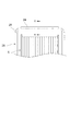
図1は、本発明の第1実施形態に係る噴霧作業機の前方斜視図、図2は、図1に示す噴霧作業機の左側面図、図3は、図1に示す噴霧作業機の平面図、図4は、図2中のIV-IV矢視図、図5は、図4中のV-V矢視図、図6は、図2中の支持体の固定部を示す拡大図である。 1 is a front perspective view of a spray working machine according to a first embodiment of the present invention, FIG. 2 is a left side view of the spray working machine shown in FIG. 1, and FIG. 3 is a plan view of the spray working machine shown in FIG. 4 is a view taken along the line IV-IV in FIG. 2, FIG. 5 is a view taken along the line VV in FIG. 4, and FIG. 6 is an enlarged view showing a fixing portion of the support in FIG.
図1〜図3に示すように、本実施形態に係る噴霧作業機100は、液体を収容可能なタンク1と、当該タンク1内の液体を吸引し排出するポンプ(動噴)2と、当該ポンプ2を駆動する動力源3(ここでは内燃機関)と、ポンプ2から排出されたタンク1内の液体を送り出し噴霧する噴霧ホース4と、当該噴霧ホース4を巻き取るホースリール5とを台車6に搭載して構成されている。また、台車6は作業者が把持するためのハンドル7を備えており、作業者はハンドル7を把持し、台車6を手押し車のように押し引きして移動させることが可能となっている。以下、ハンドル7の設けられている側(図2の右側)を噴霧作業機100の後側とする。
As shown in FIGS. 1 to 3, the
台車6は、上記各要素を搭載する台座部13を備え、当該台座部13の前側には、軸心が左右方向に延びる一対の前輪8,8が回転自在に支持されており、台座部13の後側には、左右一対の後輪9,9が回転自在に支持されている。この後輪9,9は、その軸心の向きを水平面内で自在に変えられるようになっており、台車6の方向転換が容易となっている。
The
このように移動自在に構成された台車6の上部には、台座部13の前側から鉛直に立ち上がり、後方へ延びる左右一対の上部フレーム10,10が設けられており、さらに各々の上部フレーム10,10の後端に連設して上方且つ後方に延びる一対のハンドル支持フレーム11,11が設けられている。この一対のハンドル支持フレーム11,11の後端同士は左右に伸びるフレームで繋がれており、この左右に延びるフレームが作業者の把持する把持フレーム12を構成している。そして、ハンドル支持フレーム11,11及び把持フレーム12により上記ハンドル7が構成されている。
A pair of left and right
台車6の台座部13と上部フレーム10,10との間には、上記タンク1が載置されている。このタンク1の上部前側(図2の左側)には液体を注入するための注入口が形成されており、当該注入口がキャップ14により封止されている。
The
また、タンク1の後方で、かつハンドル7の下方には、荷物を収容可能な荷物籠15が取り付けられている。
A
一対の上部フレーム10,10の上部前側には、ポンプ2およびその動力源3からなるポンプセット27が載置されている。
A
また、左右一対の上部フレーム10,10の上部後側には、ホースリール5を取り付けるための左右一対のリール台16,16が各々設けられており、一対のリール台16,16の上に、一対の軸受体17,17が各々載置されている。
Further, on the upper rear side of the pair of left and right
ホースリール5は、噴霧ホース4を巻きつけるための芯体19と、この芯体19の軸心方向両端において噴霧ホース4の脱落を防止する一対の円環状板20,20とを有している。さらに、ホースリール5は、芯体19の両端に連設され、一対の円環状板20,20の左右外側に突出した一対の円柱体21,21を各々有しており、この円柱体21,21が上記一対の軸受体17,17に各々回転自在に支持されている。このようにして、ホースリール5が台車6に支持され、左右に延びる軸心回りに回転自在となっている。また、円柱体21,21の一方(ここでは右側の円柱体21)の端には、クランク状のハンドル22が連結されており、ハンドル22を把持してホースリール5を回転させることが可能となっている。
The
ホースリール5には、上記噴霧ホース4が巻き取られている。また、噴霧ホース4の先端には噴霧ノズル23が取り付けられ、この噴霧ノズル23から液体が噴霧されるようになっている。そして、ホースリール5に巻き取られた噴霧ホース4を引き出し、または引き出された噴霧ホース4をホースリール5に巻き戻すことで噴霧ホース4の引き出し長を適宜調整しながら噴霧作業を行うことが可能となっている。
The
ここで、噴霧ホース4の引き出しや巻取りをガイドするためのループ体24と、それを支持するための支持体25について説明する。
Here, the
支持体25は、前後方向に並設された一対の支持フレーム26,26を有し、各々の支持フレーム26,26はパイプ材から形成されている(図5参照)。なお、フレーム26,26の素材は円柱材であってもよい。この一対の支持フレーム26,26は、正面視において各々コの字形状に形成されており、その開口側を下方に向け開口内にホースリール5を収容した状態で配置されている(図4参照)。
The
図6に示すように、各々の支持フレーム26の両下端部には、おねじ部26b,26bが各々形成されており、このおねじ部26b,26bによって各々の支持フレーム26の両下端部が上記左右一対のリール台16,16に取り付けられている。詳しくは、上記一対の軸受体17,17に上下方向に貫通する孔が形成され、一対のリール台16,16の対応する位置にも上下方向に貫通する孔が形成され、これらの孔に上方から支持フレーム26の両下端のおねじ部26b,26bが挿通されている。そして、一対のリール台16,16の裏側のナット28,28がおねじ部26b,26bに対して締め付けられ、支持フレーム26の両端部が一対の軸受体17,17と共に一対のリール台16,16に各々取り付けられている。なお、おねじ部26bを挿通するための孔は、軸受体17およびリール台16の前部および後部に形成されており、前側の孔において前側の支持フレーム26が取り付けられ、後側の孔において後側の支持フレーム26が取り付けられている。
As shown in FIG. 6,
図1〜図3に示すように、一対の支持フレーム26,26の左右方向に延びる上部は、ホースリール5の上方を左右に横切り、その上にループ体24が載置されている(図4参照)。ループ体24は、パイプ材(又は円柱材)からなるフレームであり(図5参照)、平面視において左右方向に延びる長円状に構成されている。そして、ループ体24の左右方向の幅は、ホースリール5の左右方向の幅と同等となっている。このように形成されたループ体24は、左右方向に延びる前後一対の直線部分を一対の支持フレーム26,26の上部に各々重ねるようにして、一対の支持フレーム26,26に載置されて連結されている。この連結状態において、一対の支持フレーム26,26の左右方向に延びる上部は、ループ体24の左右方向に延びる前後一対の直線部分に対し、ループ体24のなす環形状の内側にずらして配置されている(図5参照)。
As shown in FIGS. 1-3, the upper part extended in the left-right direction of a pair of support frames 26 and 26 crosses the upper direction of the
以上のように構成された噴霧作業機100によれば、噴霧ホース4が上下方向に挿通可能な環形状のループ体24を備え、このループ体24がホースリール5の軸心方向に延び、当該軸心方向においてホースリール5と同等の幅を有する横長形状とされているため、噴霧ホース4はいずれの方向に引き出されても小さなループ体24を通してホースリール5上に導かれる。これにより、小型化を図りつつ、360度全方位に対し噴霧ホース(4)のスムーズな引き出し及び巻き取りが可能となる。
According to the
また、本実施形態では、ループ体24及び支持体25のフレームは、噴霧ホース4と接触しても噴霧ホース4を損傷しないように断面が円弧状の部分を有し、支持体25のフレームはループ体24のフレームよりもループ体24のなす環形状の内側にずらして配置されているため、噴霧ホース4が支持体25のフレームとループ体24のフレームの双方に当接することになり、フレームと噴霧ホース4との接触圧力が分散され、噴霧ホース4の引き出し及び巻き取りがよりスムーズになる。
In the present embodiment, the frame of the
また、支持体25を構成する支持フレーム26の両端部のおねじ部26b,26bにナット28,28を締め付けることで、支持フレーム26及び一対の軸受体17,17をリール台16,16に共締めできるため、部品点数を削減し低コスト化を図ることができる。
Further, by tightening the nuts 28 and 28 to the
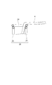
次に、本発明による噴霧作業機の第2実施形態を説明する。図7は、本発明の第2実施形態に係る噴霧作業機のループ体および支持体を示す背面図である。 Next, a second embodiment of the spray working machine according to the present invention will be described. FIG. 7 is a rear view showing the loop body and the support body of the spray working machine according to the second embodiment of the present invention.
この第2実施形態が第1実施形態と違う点は、図7に示すように、上記ループ体24に代えて、左右の端部が左右外側に行くに従って上方へ向かうように傾斜したループ体29を用いると共に、上記支持フレーム26,26に代えて、左右方向に延びる上部の形状をループ体29の形状に合わせて傾斜させた支持フレーム31,31を用いた点である。
The second embodiment is different from the first embodiment in that, as shown in FIG. 7, instead of the
本実施形態によれば、ループ体29の延伸方向の両端部が、当該両端部以外の部分よりも高くなっているため、ホースリール5の軸心方向に噴霧ホース4が引き出された場合に、噴霧ホース4がループ体29と接触する位置が高くなり、噴霧ホース4を引き回しやすくなるため、噴霧ホース4の引き出し及び巻き取りがよりスムーズになる。
According to this embodiment, since both ends in the extending direction of the
なお、第1、第2実施形態では、タンク1を含む各要素が台車6に搭載された構成を示したが、本発明による噴霧作業機はこのような構成に限られるものではない。例えば、タンク1を搭載せず外部の貯水槽等を利用する構成であってもよいし、台車6に搭載せず作業者が持ち上げて運搬する構成であってもよい。
In the first and second embodiments, the configuration in which each element including the
1…タンク、2…ポンプ、3…動力源、4…噴霧ホース、5…ホースリール、6…台車、24…ループ体、25…支持体、100…噴霧作業機。
DESCRIPTION OF
Claims (3)
前記ホースリール(5)の上方に水平に配置され、前記噴霧ホース(4)が上下方向に挿通可能な環形状のループ体(24)を備え、
前記ループ体(24)は横長形状をなし、当該横長形状の延伸方向が前記ホースリール(5)の軸心方向を向くように配置され、当該軸心方向において前記ホースリール(5)と同等の幅を有するように構成されていることを特徴とする噴霧作業機(100)。 A pump (2) for sucking and discharging liquid, a power source (3) for driving the pump (2), a spray hose (4) for sending and spraying the liquid discharged from the pump (2), and the spray In a spray working machine (100) having a hose reel (5) for winding a hose (4),
It is arranged horizontally above the hose reel (5), and the spray hose (4) includes an annular loop body (24) that can be inserted vertically.
The loop body (24) has a horizontally long shape, and is arranged so that the extending direction of the horizontally long shape faces the axial direction of the hose reel (5), and is equivalent to the hose reel (5) in the axial direction. A spray working machine (100) characterized by having a width.
前記ループ体(24)及び前記支持体(25)は、それぞれ断面が円弧状の部分を有するフレームからなり、
前記支持体(25)のフレームは前記ループ体(24)のフレームよりも前記ループ体(24)のなす環形状の内側にずらして配置されていることを特徴とする請求項1記載の噴霧作業機(100)。 A support body (25) for supporting the loop body (24) from below;
The loop body (24) and the support body (25) are each composed of a frame having a circular arc section.
The spraying operation according to claim 1, wherein the frame of the support body (25) is arranged so as to be shifted from the frame of the loop body (24) inside the ring shape formed by the loop body (24). Machine (100).
Priority Applications (1)
| Application Number | Priority Date | Filing Date | Title |
|---|---|---|---|
| JP2010154041A JP5395002B2 (en) | 2010-07-06 | 2010-07-06 | Spraying machine |
Applications Claiming Priority (1)
| Application Number | Priority Date | Filing Date | Title |
|---|---|---|---|
| JP2010154041A JP5395002B2 (en) | 2010-07-06 | 2010-07-06 | Spraying machine |
Publications (2)
| Publication Number | Publication Date |
|---|---|
| JP2012017156A true JP2012017156A (en) | 2012-01-26 |
| JP5395002B2 JP5395002B2 (en) | 2014-01-22 |
Family
ID=45602697
Family Applications (1)
| Application Number | Title | Priority Date | Filing Date |
|---|---|---|---|
| JP2010154041A Active JP5395002B2 (en) | 2010-07-06 | 2010-07-06 | Spraying machine |
Country Status (1)
| Country | Link |
|---|---|
| JP (1) | JP5395002B2 (en) |
Citations (4)
| Publication number | Priority date | Publication date | Assignee | Title |
|---|---|---|---|---|
| JPS59153966U (en) * | 1982-12-06 | 1984-10-16 | 三菱重工業株式会社 | Hose storage reel |
| JPS6256579U (en) * | 1985-09-25 | 1987-04-08 | ||
| US5303866A (en) * | 1992-09-11 | 1994-04-19 | Hawks Jr Bill J | Integrated modular spraying system |
| WO2004089798A1 (en) * | 2003-04-09 | 2004-10-21 | Donovin Cronning | A hose reel |
-
2010
- 2010-07-06 JP JP2010154041A patent/JP5395002B2/en active Active
Patent Citations (4)
| Publication number | Priority date | Publication date | Assignee | Title |
|---|---|---|---|---|
| JPS59153966U (en) * | 1982-12-06 | 1984-10-16 | 三菱重工業株式会社 | Hose storage reel |
| JPS6256579U (en) * | 1985-09-25 | 1987-04-08 | ||
| US5303866A (en) * | 1992-09-11 | 1994-04-19 | Hawks Jr Bill J | Integrated modular spraying system |
| WO2004089798A1 (en) * | 2003-04-09 | 2004-10-21 | Donovin Cronning | A hose reel |
Also Published As
| Publication number | Publication date |
|---|---|
| JP5395002B2 (en) | 2014-01-22 |
Similar Documents
| Publication | Publication Date | Title |
|---|---|---|
| CN104209291A (en) | Pressure washer with hose reel and motor pump assembly | |
| JP5395002B2 (en) | Spraying machine | |
| CN208964265U (en) | It is a kind of for coiling the device of pipeline, cable | |
| CN202765986U (en) | Hose winding machine | |
| CN105947668B (en) | A kind of vacuum suction suspender and its application method | |
| CN202860887U (en) | High-pressure cleaning machine with pipe-rolling device | |
| CN104973459A (en) | Textile machine yarn bobbin facilitating guiding of yarn | |
| CN203784057U (en) | Large box fastening device for transportation | |
| KR200437068Y1 (en) | carrier for gas welding machine | |
| JP6382730B2 (en) | Assist suit | |
| KR200389042Y1 (en) | a cable reel | |
| CN202321829U (en) | Bamboo mat reel | |
| JP3111423U (en) | Single winding rudder wheel hose reel | |
| CN105819264A (en) | Steering bending frame for plastic package | |
| CN202238966U (en) | Novel pay-off system structure for wire drawing machine | |
| CN206203583U (en) | Large-scale unwrapping wire wheel apparatus | |
| CN105016142A (en) | Wire take-up device of multi-wire sawing machine | |
| CN209143360U (en) | A kind of textile bobbin pallet | |
| CN205132761U (en) | Automatic wire reel of movable | |
| CN105790004B (en) | Portable winding disk | |
| CN105502090A (en) | Concentration apparatus of ice maker cables | |
| CN208199292U (en) | A kind of environmental protection mixed yarn spinning cradle spinning rack | |
| CN203855194U (en) | Air expansion shaft clamping mechanism for uncoiling machine | |
| KR20110010143U (en) | Hose reel combination agricultural chemical atomizer | |
| CN210319348U (en) | Welding machine guide rail lubricating arrangement |
Legal Events
| Date | Code | Title | Description |
|---|---|---|---|
| A621 | Written request for application examination |
Free format text: JAPANESE INTERMEDIATE CODE: A621 Effective date: 20120507 |
|
| A977 | Report on retrieval |
Free format text: JAPANESE INTERMEDIATE CODE: A971007 Effective date: 20130722 |
|
| A131 | Notification of reasons for refusal |
Free format text: JAPANESE INTERMEDIATE CODE: A131 Effective date: 20130730 |
|
| A521 | Written amendment |
Free format text: JAPANESE INTERMEDIATE CODE: A523 Effective date: 20130917 |
|
| A977 | Report on retrieval |
Free format text: JAPANESE INTERMEDIATE CODE: A971007 Effective date: 20130917 |
|
| TRDD | Decision of grant or rejection written | ||
| A01 | Written decision to grant a patent or to grant a registration (utility model) |
Free format text: JAPANESE INTERMEDIATE CODE: A01 Effective date: 20131015 |
|
| A61 | First payment of annual fees (during grant procedure) |
Free format text: JAPANESE INTERMEDIATE CODE: A61 Effective date: 20131017 |
|
| R150 | Certificate of patent or registration of utility model |
Ref document number: 5395002 Country of ref document: JP Free format text: JAPANESE INTERMEDIATE CODE: R150 Free format text: JAPANESE INTERMEDIATE CODE: R150 |