JP2012012143A - Security workbench for opening and closing box, security system when opening and closing box, and method for opening and closing box using the security system - Google Patents
Security workbench for opening and closing box, security system when opening and closing box, and method for opening and closing box using the security system Download PDFInfo
- Publication number
- JP2012012143A JP2012012143A JP2010148631A JP2010148631A JP2012012143A JP 2012012143 A JP2012012143 A JP 2012012143A JP 2010148631 A JP2010148631 A JP 2010148631A JP 2010148631 A JP2010148631 A JP 2010148631A JP 2012012143 A JP2012012143 A JP 2012012143A
- Authority
- JP
- Japan
- Prior art keywords
- box
- shooting
- camera
- digital camera
- opening
- Prior art date
- Legal status (The legal status is an assumption and is not a legal conclusion. Google has not performed a legal analysis and makes no representation as to the accuracy of the status listed.)
- Pending
Links
Images


Landscapes
- Warehouses Or Storage Devices (AREA)
Abstract
Description
本発明は、箱開閉用セキュリティ作業台、箱開閉時のセキュリティシステム、及びこのセキュリティシステムを用いた箱開閉方法に関する。 The present invention relates to a box opening / closing security work table, a box opening / closing security system, and a box opening / closing method using the security system.
従来より、顧客に対して倉庫などの物品の保管スペースのみを提供する物品の保管システムが知られている。
顧客が、例えば機密書類などの物品をダンボール箱に収納して封印し、倉庫の管理会社に対して預け入れると、管理会社は、預かったダンボール箱を開梱包することなく、箱単位で倉庫内に保管・管理を行う。このとき、一般には、倉庫入り口に認証鍵などが備えられ、人の入退室管理が行われるとともに、倉庫内をデジタルカメラにより監視・記録するなどして、セキュリティ確保が為されている(例えば、特許文献1参照)。
そして、顧客から問い合わせがあった場合には、管理会社は箱を開梱包することなく、箱単位で顧客に返却を行い、顧客は自ら箱を開梱包して所望の書類を捜索する。
このシステムは、管理会社側でダンボール箱の開梱包がなされることがないため、書類の紛失及び情報漏えいのリスクが少ないというメリットを有する。
2. Description of the Related Art Conventionally, an article storage system that provides only a storage space for articles such as a warehouse to customers is known.
When a customer puts an item such as a confidential document in a cardboard box and seals it and deposits it in a warehouse management company, the management company puts the stored cardboard box in the warehouse in units of boxes without unpacking it. Store and manage. At this time, generally, an authentication key or the like is provided at the entrance of the warehouse, and entrance / exit management of people is performed, and security is ensured by monitoring and recording the inside of the warehouse with a digital camera (for example, Patent Document 1).
And when there is an inquiry from a customer, the management company returns it to the customer in units of boxes without unpacking the boxes, and the customer unpacks the boxes and searches for a desired document.
This system has the advantage that the risk of document loss and information leakage is low because the management company does not unpack the cardboard box.
ところが、上記のようなシステムに対しては、顧客側から、問い合わせから書類を確認するまでに掛かる時間を短縮させたい、書類の確認後に再度箱を送り返すなど煩雑な処理を簡略化したい、また、箱の搬送に伴うリスクを軽減させたいなどの要望がある。
この要望に対して、例えば、管理会社側で箱を開梱包して所望の書類を捜索し、顧客にファクシミリなどで送信するなどの方法が考えられる。
しかしながら、管理会社側で箱を開梱包して書類の捜索をすると、どうしても紛失等のリスクが高くなってしまうという問題がある。この点、たとえ倉庫内をデジタルカメラにより撮像したデジタル画像の記録があったとしても、当該デジタル画像は改ざんされる恐れがあり、裁判において当該デジタル画像を証拠として提出しても裁判所で証拠として採用されにくいという実情があり、現実的な対応策として得策とはいえない。
このように、上記したような顧客の要望に応え得る物品の保管システムは、未だ提案されていない。
However, for the above system, the customer wants to reduce the time it takes to check the document from the inquiry, to simplify complicated processing such as sending back the box again after checking the document, There is a demand to reduce the risks associated with transporting boxes.
In response to this demand, for example, a method is conceivable in which a management company unpacks a box, searches for a desired document, and transmits it to a customer by facsimile or the like.
However, when the management company unpacks the box and searches for the document, there is a problem that the risk of loss or the like inevitably increases. In this regard, even if there is a record of a digital image captured in the warehouse by a digital camera, the digital image may be tampered with, and even if the digital image is submitted as evidence in a trial, it is adopted as evidence in the court There is a fact that it is difficult to be done, and it cannot be said that it is a good solution as a realistic countermeasure.
As described above, an article storage system that can meet the demands of customers as described above has not yet been proposed.
本発明の課題は、セキュリティを保ちつつ、顧客側の作業負荷の低減を図ることのできる箱開閉用セキュリティ作業台、箱開閉時のセキュリティシステム、及びこのセキュリティシステムを用いた箱開閉方法を提供することである。 SUMMARY OF THE INVENTION An object of the present invention is to provide a box opening / closing security work table, a security system for opening / closing a box, and a box opening / closing method using the security system, which can reduce the workload on the customer side while maintaining security. That is.
前記課題を解決するために、請求項1に記載の発明は、箱開閉用セキュリティ作業台において、
上面から開梱包される箱体を設置するための箱体設置部を有するテーブルと、
前記箱体設置部の上方に配され、当該箱体設置部を動画及び静止画撮影するデジタルカメラと、
前記箱体設置部の上方に配され、当該箱体設置部を静止画撮影するフィルムカメラと、を備え、
前記デジタルカメラは、前記箱体が前記箱体設置部に設置されてから開梱包されるまでの間に撮影を開始し、前記箱体が再梱包されてから前記箱体設置部から撤去されるまでの間に撮影を終了し、
前記フィルムカメラは、前記デジタルカメラが動画撮影している期間内に、1乃至複数回撮影を行うことを特徴とする。
In order to solve the above problems, the invention according to claim 1 is a security work table for opening and closing a box.
A table having a box installation unit for installing a box to be unpacked from the upper surface;
A digital camera that is arranged above the box body setting unit and shoots a moving image and a still image of the box setting unit;
A film camera that is arranged above the box installation unit and shoots a still image of the box installation unit;
The digital camera starts shooting after the box is installed in the box installation unit until it is unpacked, and is removed from the box installation unit after the box is repacked. Until the end of shooting,
The film camera shoots one or more times within a period during which the digital camera shoots a moving image.
また、請求項2に記載の発明は、請求項1記載の箱開閉用セキュリティ作業台において、
前記デジタルカメラ及び前記フィルムカメラの撮影開始タイミングを検知する検知手段と、
前記検知手段による撮影開始タイミングの検知に基づいて、前記デジタルカメラ及び前記フィルムカメラによる撮影を開始させる開始制御手段と、
を備えることを特徴とする。
The invention according to claim 2 is the security work table for opening and closing the box according to claim 1,
Detection means for detecting the shooting start timing of the digital camera and the film camera;
Start control means for starting photographing by the digital camera and the film camera based on detection of photographing start timing by the detecting means;
It is characterized by providing.
また、請求項3に記載の発明は、請求項2に記載の箱開閉用セキュリティ作業台において、
前記箱体は、IC(Integrated Circuits)タグ付き施錠機構により封印され、
前記検知手段は、前記施錠機構の解除手段を備え、
前記開始制御手段は、前記解除手段による前記施錠機構の解除タイミングを前記撮影開始タイミングとして、前記デジタルカメラ及び前記フィルムカメラによる撮影を開始させることを特徴とする。
The invention according to claim 3 is the security work table for opening and closing the box according to claim 2,
The box is sealed by a locking mechanism with an IC (Integrated Circuits) tag,
The detection means includes release means for the locking mechanism,
The start control means starts shooting with the digital camera and the film camera with the release timing of the locking mechanism by the release means as the shooting start timing.
また、請求項4に記載の発明は、箱開閉時のセキュリティシステムにおいて、
請求項1〜3の何れか一項に記載の箱開閉用セキュリティ作業台と、
権限を有する者以外の立ち入りが制限され、前記箱開閉用セキュリティ作業台が設置された作業室と、
前記作業室内に配置され、入室者の入室時から退出時まで当該作業室内を動画及び静止画撮影する室内監視カメラと、
前記作業室内に配置され、前記箱体が開梱包されて所定の書類が取得された場合に当該所定の書類のデータを顧客に対して送信する書類データ送信手段と、
前記室内監視カメラ及び前記デジタルカメラが撮影した静止画像の画像データに対して、外部認証機関にタイムスタンプの発行を依頼し、前記外部認証機関から前記タイムスタンプを取得するタイムスタンプ発行依頼手段と、
を備えることを特徴とする。
The invention according to claim 4 is a security system when opening and closing a box.
A security work table for opening and closing the box according to any one of claims 1 to 3,
A work room in which access to persons other than authorized persons is restricted, and the box opening / closing security worktable is installed,
An indoor surveillance camera that is arranged in the work room and shoots a moving image and a still image of the work room from the time of entering the room to the time of leaving,
Document data transmitting means that is arranged in the working chamber and transmits the data of the predetermined document to the customer when the box is opened and a predetermined document is acquired;
A time stamp issuance requesting unit for requesting an issuance of a time stamp to an external certification authority for image data of a still image taken by the indoor monitoring camera and the digital camera, and acquiring the time stamp from the external certification authority,
It is characterized by providing.
また、請求項5に記載の発明は、
請求項4に記載の箱開閉時のセキュリティシステムを用いた箱開閉方法であって、
箱体を持った入室者が前記作業室に入室すると、前記室内監視カメラによる撮影を開始する室内撮影開始工程と、
前記箱体が前記テーブルの前記箱体設置部に設置されてから開梱包されるまでに、前記デジタルカメラ及び前記フィルムカメラによる撮影を開始する作業撮影開始工程と、
前記箱体の中から取得された前記所定の書類を前記書類データ送信手段により顧客に送信する書類データ送信工程と、
前記箱体の中に前記所定の書類が収納され、当該箱体が再梱包されてから前記箱体設置部から撤去されるまでに、前記デジタルカメラ及び前記フィルムカメラによる撮影を停止する作業撮影停止工程と、
前記箱体を持った入室者が前記作業室から退室すると、前記室内監視カメラによる撮影を停止する室内撮影停止工程と、
前記室内監視カメラ及び前記デジタルカメラが撮影した静止画像の画像データに対して、前記タイムスタンプ発行依頼手段による依頼に基づいて前記外部認証機関から発行された前記タイムスタンプを取得するタイムスタンプ取得工程と、
前記タイムスタンプ取得工程により前記タイムスタンプを取得したタイムスタンプ付き画像データを、顧客に対して送信するタイムスタンプ付きデータ送信工程と、
を備えることを特徴とする。
The invention according to claim 5
A box opening and closing method using the security system at the time of opening and closing the box according to claim 4,
When a room entrant with a box enters the working room, an indoor shooting start step for starting shooting with the indoor monitoring camera;
From the time when the box is installed in the box setting part of the table until it is unpacked, a work shooting start step for starting shooting with the digital camera and the film camera,
A document data transmission step of transmitting the predetermined document acquired from the box to a customer by the document data transmission means;
The work document is stopped when the predetermined document is stored in the box and the digital camera and the film camera are stopped from the repacking until the box is removed from the box installation unit. Process,
When the occupant with the box leaves the work room, an indoor shooting stop process for stopping shooting by the indoor monitoring camera;
A time stamp acquisition step of acquiring the time stamp issued from the external certification body based on a request from the time stamp issuance requesting unit for image data of a still image taken by the indoor monitoring camera and the digital camera; ,
The time-stamped image data obtained by sending the time-stamped image data obtained by the time stamp obtaining step to the customer;
It is characterized by providing.
本発明によれば、梱包開閉の全作業がデジタルカメラ及びフィルムカメラにより同時に撮影されるため、箱体を開梱包して書類の捜索をする場合の全作業を、デジタルカメラと、画像の改ざんが不可能なフィルムカメラと、により記録に残すことができる。これにより、裁判においてデジタルカメラの画像とフィルムカメラの画像を両方証拠として提出することで、デジタルカメラの画像の証拠能力を高めることができ、裁判所で証拠として採用されやすくなる。
このため、顧客から問い合わせがあった際に、セキュリティを保ちつつ、箱体の開閉作業を行うことができる。よって、顧客は、問い合わせただけで、煩雑な処理や搬送リスクが発生することなく、短時間で所望の書類のみを確認することができるようになる。
従って、セキュリティを保ちつつ、顧客側の作業負荷の低減を図ることができる。
According to the present invention, since all the operations for opening and closing the packaging are simultaneously photographed by the digital camera and the film camera, all operations when opening the box and searching for the document are performed with the digital camera and image alteration. With an impossible film camera, you can leave a record. Thereby, by submitting both the digital camera image and the film camera image as evidence in a trial, the evidence capability of the digital camera image can be enhanced, and it becomes easier to be adopted as evidence in the court.
For this reason, when there is an inquiry from a customer, the box body can be opened and closed while maintaining security. Therefore, the customer can confirm only the desired document in a short time without incurring complicated processing and transport risk simply by making an inquiry.
Therefore, it is possible to reduce the workload on the customer side while maintaining security.
以下、図面を参照して、本発明の実施形態について詳細に説明する。 Hereinafter, embodiments of the present invention will be described in detail with reference to the drawings.
(第1実施形態)
本実施形態のセキュリティシステム(箱開閉時のセキュリティシステム)100は、管理会社が顧客から預かりいれて倉庫などに保管しているダンボール箱などの箱体Bを、管理会社が顧客からの依頼に応じて開梱包して箱体B内に収容された物品を捜索作業する際などに使用されるシステムである。
箱体Bには、顧客側で発生した、当面使用しないが後に必要となる場合を考慮して保管される、各種の秘密情報などの記載された重要書類などが収納されており、箱体Bの外面には、顧客名、箱番号、書類名などが明記されている。
管理会社は、顧客から、書類を捜索する依頼状を受領すると、この依頼状に記載された箱番号や対象書類などの依頼情報に基づいて、倉庫内に保管された多数の箱体Bの中から該当する箱体Bをピックアップし、作業室10(後述)に運びこんで箱体Bの開閉作業を行う。
(First embodiment)
The security system (security system at the time of opening and closing the box) 100 according to the present embodiment is configured so that the management company responds to a request from the customer for the box B such as a cardboard box that is stored in the warehouse by the management company. It is a system used when searching for an article that has been unpacked and accommodated in the box B.
Box B contains important documents such as various confidential information that are stored at the customer's side and are not used for the time being but will be needed later. The customer name, box number, document name, etc. are clearly stated on the outside.
When the management company receives a request for searching for a document from a customer, the management company selects a number of boxes B stored in the warehouse based on the request information such as the box number and the target document described in the request. The corresponding box B is picked up and carried into the work chamber 10 (described later) to open and close the box B.
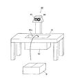
具体的に、セキュリティシステム100は、図1に示すように、作業室10と、カードリーダ20と、室内監視カメラ30と、作業台(箱開閉用セキュリティ作業台)40と、送信装置(書類データ送信手段)50と、表示部60と、操作部70と、制御装置80と、等を備えて構成されている。
Specifically, as shown in FIG. 1, the
作業室10は、箱体Bの開閉作業(書類の捜索作業)を行う専用フロアであり、例えば、箱体Bを管理する倉庫内などに、外部とは区切られて設置される。
作業室10は、一箇所のみ出入口として入室扉11が設置されている以外は、物理的に外部とは遮断されており、入室権限を有する限られた者のみが、事前登録の基に書類の捜索等の目的にて入室することができる。
The
The
入室扉11には、その外側及び内側にそれぞれカードリーダ20が設置されている。
作業室10内に入室する入室者(作業者)は、閉ざされた入室扉11に設置されたカードリーダ20に自身固有のIDカードを面接触させID情報を読み込ませる。そのID情報が既登録情報と一致すれば、入室扉11は開き、入室が可能となる。
カードリーダ20は、作業者のID情報を読み込むと、入室検知信号を制御装置80に出力する。そして、カードリーダ20からの当該入室検知信号に基づいて、制御装置80は室内監視カメラ30の撮影を開始する開始指示信号を出力する。
また、作業室10からの退室時にも同様に、カードリーダ20にID情報を読み込ませる手順が実行され、カードリーダ20から退室検知信号が出力されると、制御装置80は室内監視カメラ30の撮影を停止する停止指示信号を出力する。
The
A person who enters the work room 10 (worker) causes the
When the
Similarly, when leaving the
作業室10内部の天井部には、室内監視カメラ30が設置されている。
室内監視カメラ30は、入室扉11を含む作業室10の室内全体を監視可能に取り付けられており、作業室10に作業者が入室した場合には、その入室者が退室するまで、室内全体を動画撮影及び静止画撮影する。
具体的には、室内監視カメラ30は、作業室10に作業者が入室した場合に制御装置80から出力される開始指示信号に応じて動画撮影を開始し、当該作業者が作業室10から退室した場合に制御装置80から出力される停止指示信号に応じて動画撮影を停止する。なお、動画撮影の停止は、作業者が作業室10から退室して入室扉11が閉められた数秒後(例えば、15秒後など)となるように設定されている。
また、室内監視カメラ30は、制御装置80からの開始指示信号に応じて、例えば、作業者の入退室時などの所定のタイミングで静止画撮影を実行する。
なお、入退室時以外にも、動画撮影を実行している期間内に一定時間毎(例えば、2秒毎)に連続的に静止画撮影を実行することとしても良い。
室内監視カメラ30により撮影された動画及び静止画は、制御装置80の室内画像記憶部83A(後述)に保存される。
作業室10は、このようなカードリーダ20及び室内監視カメラ30を備えることで、入退室管理が徹底され、室内滞在者を常に確実に把握することができるようになっている。
なお、室内監視カメラ30の数に特に限定はなく、複数個設置することとしても良い。また、室内監視カメラ30に、作業者を認識して追尾する機構を設けても良い。
An
The
Specifically, the
In addition, the
Note that, in addition to the time of entering and leaving the room, still image shooting may be executed continuously at regular intervals (for example, every 2 seconds) within a period during which moving image shooting is executed.
A moving image and a still image captured by the
The
The number of
作業台40は、作業者が外部から運びこんだ箱体Bの開閉作業を行う為の専用台である。
作業室10内で箱体Bの開閉作業を行う場合、全ての箱体Bはこの作業台40上に設置されて上面から開閉されるが、このとき一連の開閉業が撮影されるようになっている。
The work table 40 is a dedicated table for performing an opening / closing operation of the box B carried by the worker from the outside.
When the box body B is opened and closed in the
具体的に、作業台40は、テーブル41と、デジタルカメラ43と、フィルムカメラ44と、を備えて構成されている。
Specifically, the work table 40 includes a table 41, a
テーブル41は、図2に示すように、箱体Bを設置するための凹形状の箱体設置部42を備えている。
箱体設置部42の内部には箱センサ(検知手段)42aが設置されている。
箱センサ42aは、例えば、光センサなどにより構成され、箱体設置部42に箱体Bが設置されるとこれを検知して、デジタルカメラ43及びフィルムカメラ44の撮影開始タイミングとして、制御装置80に第1検知信号を出力する。すると、制御装置80からは、デジタルカメラ43及びフィルムカメラ44の撮影を開始する開始指示信号が出力されて、デジタルカメラ43及びフィルムカメラ44の撮影が開始されるようになっている。
また、箱センサ42aは、箱体Bが箱体設置部42から撤去されるとこれを検知して、デジタルカメラ43及びフィルムカメラ44の撮影停止タイミングとして第2検知信号を制御装置80に出力する。すると、制御装置80からは、デジタルカメラ43及びフィルムカメラ44の撮影を停止する停止指示信号が出力され、デジタルカメラ43及びフィルムカメラ44の撮影が停止されるようになっている。
即ち、本実施形態においては、箱体設置部42に箱体Bが設置された時点から、撤去された時点まで、デジタルカメラ43及びフィルムカメラ44の撮影が行われる。
As shown in FIG. 2, the table 41 includes a concave box
A box sensor (detection means) 42 a is installed inside the box
The
Further, the
That is, in the present embodiment, the
デジタルカメラ43は、箱体設置部42の上方において、当該箱体設置部42の全体を撮影可能なように配置されており、箱体Bの開閉作業を動画及び静止画で撮影する。
具体的に、デジタルカメラ43は、制御装置80が出力した開始指示信号に基づいて、箱体Bが箱体設置部42に設置された時点で動画撮影を開始し、箱体Bが箱体設置部42から撤去された時点で動画撮影を停止する。
また、デジタルカメラ43は、制御装置80が出力した開始指示信号に基づいて、上記の動画撮影している期間内に、所定のタイミングで1乃至複数回、静止画撮影を行う。所定のタイミングとは、例えば、動画撮影の開始から2秒毎などのように、予め作業者により設定されたタイミングである。
デジタルカメラ43により撮影された動画及び静止画は、制御装置80の作業画像記憶部83B(後述)に保存される。
The
Specifically, the
Further, the
A moving image and a still image captured by the
フィルムカメラ44は、箱体設置部42の上方において、デジタルカメラ43に並設されている。フィルムカメラ44も、箱体設置部42の全体を撮影可能なように配置されており、箱体Bの開梱包作業を静止画で撮影して撮影した画像を銀塩フィルムに記録する。
具体的に、フィルムカメラ44は、制御装置80が出力した開始指示信号に基づいて、デジタルカメラ43が動画撮影している期間内に、所定のタイミングで1乃至複数回、静止画撮影を行う。
ここで、所定のタイミングとは、デジタルカメラ43が静止画撮影するタイミングと同一である。
従って、デジタルカメラ43及びフィルムカメラ44により、同じ静止画が撮影されることとなり、有事の際には2種類の静止画を照合することができるようになっている。
The
Specifically, based on the start instruction signal output from the
Here, the predetermined timing is the same as the timing at which the
Therefore, the same still image is taken by the
送信装置50は、例えば、ファクシミリなどの、紙媒体における文書や画像を電話回線によって外部に転送する機器である。
送信装置50は、作業室10内に配置されており、このため、作業者が箱体Bの内部から所定の書類を取得した場合に、その場で(作業室10から退室することなく)当該所定の書類を顧客に対して送信することができるようになっている。
なお、顧客に所定の書類を送信した後、送信装置50内の所定の書類に関わる情報は削除される。
また、送信装置50には、電話などの通話機能を備えるものを用いることとし、所定の書類の送信完了後、顧客に対して受領確認を行うことが好ましい。
The
The
Note that after the predetermined document is transmitted to the customer, the information related to the predetermined document in the
In addition, it is preferable to use a transmitter having a telephone call function such as a telephone, and confirm receipt to a customer after transmission of a predetermined document is completed.
表示部60は、例えば、液晶表示パネルであって、制御装置80から入力される表示信号に従って、各種の条件設定画面などの表示処理を行う。
The
操作部70は、例えば、キーボードなどの操作キー群であって、ユーザにより操作されると、その操作に伴う操作信号を制御装置80に出力する。なお、操作部70は、必要に応じてマウスやタッチパネルなどのポインティングデバイスや、リモートコントローラなど、その他の操作装置を備えるようにしてもよい。
操作部70は、例えば、作業者が、室内監視カメラ30や、デジタルカメラ43及びフィルムカメラ44による静止画の撮影スパンを設定する場合などに操作される。
The
The
制御装置80は、例えば、図3に示すように、CPU(Central Processing Unit)81、RAM(Random Access Memory)82、記憶部83、等を備えており、カードリーダ20、室内監視カメラ30、箱センサ42a、デジタルカメラ43、フィルムカメラ44、表示部60、及び操作部70などと接続されている。
As shown in FIG. 3, for example, the
CPU81は、例えば、記憶部83に記憶されている各種処理プログラムに従って、各種の制御処理を行う。
The
RAM82は、CPU81により演算処理されたデータを格納するワークメモリエリアを形成している。
The
記憶部83は、例えば、CPU81によって実行可能なシステムプログラムや、そのシステムプログラムで実行可能な各種処理プログラム、これら各種処理プログラムを実行する際に使用されるデータ、CPU81によって演算処理された各種処理結果のデータなどを記憶する。なお、プログラムは、コンピュータが読み取り可能なプログラムコードの形で記憶部83に記憶されている。
The
具体的に、記憶部83には、例えば、室内画像記憶部83A、作業画像記憶部83B、室内撮影開始制御プログラム831、作業撮影開始制御プログラム832、作業撮影停止制御プログラム833、室内撮影停止制御プログラム834、タイムスタンプ発行依頼プログラム835、及びデータ送信プログラム836、等が格納されている。
Specifically, the
室内画像記憶部83Aは、例えば、室内監視カメラ30により撮影された動画及び静止画を記録する。
The indoor
作業画像記憶部83Bは、例えば、デジタルカメラ43により撮影された動画及び静止画を記録する。
The work
室内撮影開始制御プログラム831は、例えば、箱体Bを持った作業者が作業室10に入室すると、室内監視カメラ30による撮影を開始する機能を、CPU81に実現させるプログラムである。
具体的に、入室扉11の外側に設置されたカードリーダ20から入室検知信号が出力されると、CPU81は、これに応じて室内監視カメラ30に対して撮影を開始する開始指示信号を出力する。
室内監視カメラ30は、この開始指示信号に応じて動画撮影を開始するとともに、動画撮影時の所定のタイミングにて、静止画を撮影する。
The indoor photographing
Specifically, when an entrance detection signal is output from the
The
作業撮影開始制御プログラム832は、例えば、箱センサ42aによる撮影開始タイミングの検知に基づいて、デジタルカメラ43及びフィルムカメラ44による撮影を開始させる機能を、CPU81に実現させるプログラムである。
具体的に、箱センサ42aから第1検知信号が出力されると、CPU81は、撮影開始タイミングであると判断し、作業撮影開始制御プログラム832を実行して、デジタルカメラ43及びフィルムカメラ44に撮影を開始する開始指示信号を出力する。
デジタルカメラ43は、この開始指示信号に応じて動画撮影を開始するとともに、動画撮影時の所定のタイミングにて、一乃至複数回静止画を撮影する。
また、フィルムカメラ44は、この開始指示信号に応じてデジタルカメラ43の動画撮影時の所定のタイミングにて、静止画を撮影する。
CPU81は、かかる作業撮影開始制御プログラム832を実行することにより、開始制御手段として機能している。
The work shooting start
Specifically, when the first detection signal is output from the
The
Further, the
The
作業撮影停止制御プログラム833は、例えば、箱体Bが再梱包されてから箱体設置部42から撤去されるまでに、デジタルカメラ43及びフィルムカメラ44による撮影を停止する機能を、CPU81に実現させるプログラムである。
具体的に、箱体設置部42に備えられた箱センサ42aから第2検知信号が出力されると、CPU81は、撮影の停止タイミングであると判断し、作業撮影停止制御プログラム833を実行して、デジタルカメラ43及びフィルムカメラ44に撮影を停止する停止指示信号を出力する。
デジタルカメラ43及びフィルムカメラ44は、この停止指示信号に応じて動画撮影を停止する。
For example, the work shooting
Specifically, when the second detection signal is output from the
The
室内撮影停止制御プログラム834は、例えば、箱体Bを持った作業者が作業室10から退室すると、室内監視カメラ30による撮影を停止する機能を、CPU81に実現させるプログラムである。
具体的に、入室扉11の内側に設置されたカードリーダ20から退室検知信号が出力されると、CPU81は、これに応じて室内監視カメラ30に撮影を停止する停止指示信号を出力する。なお、作業者が作業室10から退室して入室扉11が閉められた数秒後(例えば、15秒後など)に撮影が停止されるように、停止指示信号は、退室検知信号を受信したのち所定時間経過後に出力されるようになっている。
室内監視カメラ30は、この停止指示信号に応じて動画撮影を停止する。
The indoor photographing
Specifically, when an exit detection signal is output from the
The
タイムスタンプ発行依頼プログラム835は、室内監視カメラ30及びデジタルカメラ43が撮影した静止画像の画像データに対して、外部認証機関Tにタイムスタンプの発行を依頼し、外部認証機関Tからタイムスタンプを取得する機能を、CPU81に実現させるプログラムである。
具体的に、CPU81は、ユーザ操作に応じて、室内監視カメラ30及びデジタルカメラ43が撮影した静止画像の画像データを対象としてタイムスタンプの発行を外部認証機関Tに依頼する。
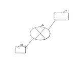
外部認証機関Tとは、図4に示すように、制御装置80と通信インタフェースNを介してネットワーク接続された一般的な認証機関であり、静止画像の画像データに対するタイムスタンプを発行する。このとき、ネットワーク接続は、SSL(Secure Socket Layer)通信などのセキュリティがある通信プロトコルを用いて行われる。
このタイムスタンプにより、静止画像の画像データが、ある日時に存在したことを外部認証機関Tにより認証されたこととなる。
CPU81は、かかるタイムスタンプ発行依頼プログラム835を実行することにより、タイムスタンプ発行依頼手段として機能している。
The time stamp
Specifically, the
As shown in FIG. 4, the external authentication authority T is a general authentication authority that is network-connected to the
By this time stamp, the external certification authority T has authenticated that the image data of the still image existed at a certain date and time.
The
データ送信プログラム836は、前記したタイムスタンプ発行依頼プログラム835の実行により、タイムスタンプを取得したタイムスタンプ付き画像データを、顧客に対して送信する機能を、CPU81に実現させるプログラムである。
具体的に、CPU81は、ユーザ操作に応じて、タイムスタンプ付き画像データを、例えば、図示しないメール機能などによって、顧客に対して送信する。
The
Specifically, the
次に、本実施形態におけるセキュリティシステム100を用いた箱開閉方法について説明する。
Next, a box opening / closing method using the
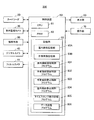
先ず、図5に、作業者の作業工程を示す。
作業者は、顧客からの依頼状を受領すると(ステップS1)、依頼状の記載内容に該当する箱体Bをピックアップする(ステップS2)。
次いで、作業者は、ピックアップした箱体Bを持って作業室10に入室し(ステップS3)、テーブル41の箱体設置部42に箱体Bを設置すると(ステップS4)、当該箱体を開梱包する(ステップS5)。
次いで、作業者は、依頼状にて依頼のあった所定の書類を箱体Bの中から取得し(ステップS6)、当該所定の書類を送信装置50により顧客に送信する(ステップS7:書類データ送信工程)。
次いで、作業者は、箱体Bの中に前記所定の書類を収納してこの箱体Bを再梱包し(ステップS8)、箱体設置部42から箱体Bを撤去する(ステップS9)。
次いで、作業者は、箱体Bを持って作業室10から退室し(ステップS10)、箱体Bを元の場所に返却する(ステップS11)。
なお、この後、作業者は、後述のステップS112、ステップS113の指示操作を実行する。
First, FIG. 5 shows an operator's work process.
When the worker receives the request from the customer (step S1), the worker picks up the box B corresponding to the contents described in the request (step S2).
Next, the worker enters the
Next, the operator acquires a predetermined document requested by the request from the box B (step S6), and transmits the predetermined document to the customer by the transmission device 50 (step S7: document data). Transmission process).
Next, the operator stores the predetermined document in the box B, repacks the box B (step S8), and removes the box B from the box installation unit 42 (step S9).
Next, the worker leaves the
After this, the worker performs an instruction operation in steps S112 and S113 described later.
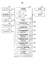
次に、図6に、セキュリティシステム100の処理工程を示す。
先ず、CPU81は、カードリーダ20からの入室検知信号が入力されたか否かを判断し(ステップS101)、入力されない場合(ステップS101:NO)、当該ステップS101の処理を繰り返す一方、入室検知信号が入力されたと判断した場合(ステップS101:YES)、CPU81は、室内監視カメラ30による作業室10内の撮影を開始する(ステップS102:室内撮影開始工程)。
次いで、CPU81は、箱センサ42aからの第1検知信号が入力されたか否かを判断し(ステップS103)、入力されない場合(ステップS103:NO)、当該ステップS103の処理を繰り返す。
一方、第1検知信号が入力されたと判断した場合(ステップS103:YES)、CPU81は、撮影開始タイミングであるとして、デジタルカメラ43及びフィルムカメラ44による撮影を開始する(ステップS104:作業撮影開始工程)。
次いで、CPU81は、デジタルカメラ43による撮影開始時点からの所定のタイミング(予め設定された撮影タイミング)になったか否かを判断し(ステップS105)、所定のタイミングになっていない場合には(ステップS105:NO)、当該ステップS105の処理を繰り返す。
一方、所定のタイミングになったと判断した場合には(ステップS105:YES)、CPU81は、デジタルカメラ43及びフィルムカメラ44により静止画の撮影を行う(ステップS106)。
次いで、CPU81は、箱センサ42aからの第2検知信号が入力されたか否かを判断し(ステップS107)、入力されない場合(ステップS107:NO)、上記ステップS105に戻って以降の処理を繰り返す。
一方、第2検知信号が入力されたと判断した場合(ステップS107:YES)、CPU81は、撮影の停止タイミングであるとして、デジタルカメラ43及びフィルムカメラ44による撮影を停止する(ステップS108:作業撮影停止工程)。
次いで、CPU81は、カードリーダ20からの退室検知信号が入力されたか否かを判断し(ステップS109)、入力されない場合(ステップS109:NO)、当該ステップS109の処理を繰り返す一方、退室検知信号が入力されたと判断した場合(ステップS109:YES)、CPU81は、更に入力された時点から所定時間経過したか否かを判断し(ステップS110)、所定時間経過していない場合には(ステップS110:NO)、当該ステップS110の処理を繰り返す。
一方、所定時間経過した場合には(ステップS110:YES)、CPU81は、室内監視カメラ30による作業室10内の撮影を停止する(ステップS111:室内撮影停止工程)。
次いで、CPU81は、作業者による指示操作に応じて、室内監視カメラ30及びデジタルカメラ43により撮影された静止画の画像データに対して、外部認証機関Tからタイムスタンプを取得する(ステップS112:タイムスタンプ取得工程)。
次いで、CPU81は、作業者による指示操作に応じて、タイムスタンプ付き画像データを顧客に対して送信する(ステップS113:タイムスタンプ付きデータ送信工程)。
Next, FIG. 6 shows processing steps of the
First, the
Next, the
On the other hand, if it is determined that the first detection signal has been input (step S103: YES), the
Next, the
On the other hand, if it is determined that the predetermined timing has come (step S105: YES), the
Next, the
On the other hand, when it is determined that the second detection signal has been input (step S107: YES), the
Next, the
On the other hand, when the predetermined time has elapsed (step S110: YES), the
Next, the
Next, the
以上のように、本実施形態によれば、箱体Bを開閉した際の全作業がデジタルカメラ43及びフィルムカメラ44により同時に撮影されるため、箱体Bを開いて書類の捜索をする場合の全作業を、デジタルカメラ43と、画像記録の改ざんが不可能なフィルムカメラ44と、により記録に残すことができる。このため、箱体Bの開閉作業を行う場合に、裁判においてデジタルカメラ43の画像とフィルムカメラ44の画像を両方証拠として提出することで、デジタルカメラ43の画像の証拠能力を高めることができ、裁判所で証拠として採用されやすくなる。
また、箱体Bの開閉作業が作業室10内でのみ行われ、作業室10内の全作業は室内監視カメラ30により記録されるため、書類の紛失等のリスクを極めて少なくすることができる。
また、デジタルカメラ43及び室内監視カメラ30が撮像した静止画像に対し、外部認証機関Tを介してタイムスタンプを付与するため、より信頼性の高い記録とすることができる。
このため、顧客から問い合わせがあった際に、セキュリティを保ちつつ、箱体Bの開閉作業を行うことができる。よって、顧客は、問い合わせただけで、煩雑な処理や搬送リスクが発生することなく、短時間で所望の書類のみを確認することができるようになる。
従って、セキュリティを保ちつつ、顧客側の作業負荷の低減を図ることができる。
As described above, according to the present embodiment, since all the operations when the box B is opened and closed are simultaneously photographed by the
In addition, the opening and closing operation of the box B is performed only in the
In addition, since a time stamp is given to the still image captured by the
For this reason, when a customer makes an inquiry, the box B can be opened and closed while maintaining security. Therefore, the customer can confirm only the desired document in a short time without incurring complicated processing and transport risk simply by making an inquiry.
Therefore, it is possible to reduce the workload on the customer side while maintaining security.
また、本実施形態によれば、箱体Bが箱体設置部42に設置されてからの所定のタイミングを検知する箱センサ42aと、箱センサ42aによる所定のタイミングの検知に基づいて、デジタルカメラ43及びフィルムカメラ44による撮影を開始させる作業撮影開始制御プログラム832と、を備えているため、適切なタイミングで箱体設置部42(開梱包作業)の撮影を開始することができる。
Further, according to the present embodiment, the digital camera is based on the
(第2実施形態)
次の、本発明の第2実施形態について図7、8を参照して説明する。
なお、第2実施形態のセキュリティシステム200は、作業台の構成が第1実施形態と異なるものであるため、この点を中心に説明する。
また、図7、8において、第1実施形態と同様の構成については、同一の符号を付している。
(Second Embodiment)
Next, a second embodiment of the present invention will be described with reference to FIGS.
Note that the
Moreover, in FIG. 7, 8, the same code | symbol is attached | subjected about the structure similar to 1st Embodiment.
本実施形態においては、箱体Bは、IC(Integrated Circuits)タグ付き施錠機構8により封印されている。
施錠機構8のICタグには、メモリ機能のあるICチップやアンテナ等が搭載されており、施錠機構8は、ICタグが所定の解除キーを捕捉した場合に開錠するようになっている。
管理会社は、顧客から、書類を捜索する依頼状を受領すると、この依頼状に記載された箱番号や対象書類などの依頼情報に基づいて、捜索対象書類の情報(解除キー等)を解除手段90(後述)に登録する。
そして、倉庫内に保管された多数の箱体Bの中から該当する箱体Bをピックアップし、作業室10に運びこんで開閉作業を行う。
In this embodiment, the box B is sealed by a
The IC tag of the
When the management company receives a request for searching for a document from a customer, the management company cancels the information on the search target document (such as a release key) based on the request information such as the box number and the target document described in the request. 90 (described later).
Then, the corresponding box B is picked up from a large number of boxes B stored in the warehouse, and is carried into the
本実施形態の作業台40Aには、図7に示すように、箱センサ42aの代わりに、施錠機構8の解除手段90が備えられている。
解除手段90は、箱体設置部42の上方のICタグ読取り装置91と、テーブル41上のICタグ解除装置92と、を備えている。
そして、箱体設置部42に設置した箱体Bを開梱包する場合、ICタグ読取り装置91によってICタグ内のデータを読取って、ICタグ解除装置92に出力する。ICタグ解除装置92は、入力されたデータが予め登録されているデータと一致する場合には、解除キーをICタグ読み取り装置91を介してICタグに送信する。ICタグが解除キーを捕捉すると、当該解除キーより施錠機構8の開錠が行われる。
また、箱体Bを再梱包する場合、ICタグ解除装置92により施錠機構8の再封印が行われる。
なお、箱体Bが開梱包された時間、再封印された時間等の履歴はICタグに記憶されるようになっている。
ここで、解除手段90は、検知手段として機能し、箱体Bの施錠機構8の解除タイミングをデジタルカメラ43及びフィルムカメラ44の撮影開始タイミングとして、制御装置80に第1検知信号を出力するようになっている。すると、制御装置80からは、デジタルカメラ43及びフィルムカメラ44の撮影を開始する開始指示信号が出力されて、デジタルカメラ43及びフィルムカメラ44の撮影が開始される。
また、解除手段90は、箱体Bが再封印されたタイミングをデジタルカメラ43及びフィルムカメラ44の撮影停止タイミングとして、第2検知信号を制御装置80に出力するようになっている。すると、制御装置80からは、デジタルカメラ43及びフィルムカメラ44の撮影を停止する停止指示信号が出力され、デジタルカメラ43及びフィルムカメラ44の撮影が停止される。
即ち、本実施形態においては、箱体Bが開梱包された時点から、再梱包された時点まで、デジタルカメラ43及びフィルムカメラ44の撮影が行われる。
As shown in FIG. 7, the work table 40A of the present embodiment is provided with a release means 90 for the
The releasing means 90 includes an IC
When unpacking the box B installed in the
When repacking the box B, the IC
A history such as the time when the box B is unpacked and the time when it is resealed is stored in the IC tag.
Here, the release means 90 functions as a detection means, and outputs the first detection signal to the
The release means 90 outputs the second detection signal to the
That is, in the present embodiment, the
このため、本実施形態においては、解除手段90から第1検知信号が出力されると、CPU81は、撮影開始タイミングであると判断し、作業撮影開始制御プログラム832を実行して、デジタルカメラ43及びフィルムカメラ44に撮影を開始する開始指示信号を出力する。
また、箱体Bが再封印され、解除手段90により第2検知信号が出力されると、CPU81は、撮影の停止タイミングであると判断し、作業撮影停止制御プログラム833を実行し、デジタルカメラ43及びフィルムカメラ44による撮影を停止する。
For this reason, in the present embodiment, when the first detection signal is output from the canceling
Further, when the box B is resealed and the second detection signal is output by the release means 90, the
以上のように、本実施形態によれば、上記第1実施形態と同様の効果が得られるのは勿論のこと、箱体BがICタグ付き施錠機構8により封印されているため、より高いセキュリティを確保することが可能である。
As described above, according to the present embodiment, the same effects as those of the first embodiment can be obtained, and since the box B is sealed by the
なお、上記第1、2実施形態においては、書類データ送信手段として、ファクシミリのような送信装置50を例示しているが、これ以外にも、書類データ送信手段を、例えば、スキャナ及び電子メールにより構成し、捜索した書類をスキャナ等で読み込んで、メールにて顧客に送信することとしても良い。
In the first and second embodiments, the
また、テーブル41に重量センサを備え、箱体Bの開梱包された時点と再梱包された時点の重量を計測し、計測した2つの重量が異なるときには警告音を発生することとしても良い。
これにより、箱体Bから取り出した書類の戻し忘れやこれに伴う紛失リスクを低減することができる。
Further, the table 41 may be provided with a weight sensor to measure the weight when the box B is unpacked and when it is repacked, and a warning sound may be generated when the two measured weights are different.
Thereby, it is possible to reduce the risk of forgetting to return the document taken out of the box B and the loss risk associated therewith.
100、200 セキュリティシステム(箱開閉時のセキュリティシステム)
10 作業室
20 カードリーダ
30 室内監視カメラ
40、40A 作業台(箱開閉用セキュリティ作業台)
41 テーブル
42 箱体設置部
42a 箱センサ(検知手段)
43 デジタルカメラ
44 フィルムカメラ
50 送信装置(書類データ送信手段)
80 制御装置
81 CPU(開始制御手段、タイムスタンプ発行依頼手段)
83 記憶部
83A 室内画像記憶部
83B 作業画像記憶部
831 室内撮影開始制御プログラム
832 作業撮影開始制御プログラム(開始制御手段)
833 作業撮影停止制御プログラム
834 室内撮影停止制御プログラム
835 タイムスタンプ発行依頼プログラム(タイムスタンプ発行依頼手段)
836 データ送信プログラム
90 解除手段(検知手段)
91 ICタグ読取り装置
92 ICタグ解除装置
8 施錠機構
T 外部認証機関
B 箱体
100, 200 Security system (security system when opening and closing the box)
DESCRIPTION OF
41 Table 42
43
80
83
833 Work shooting
836
91 IC
Claims (5)
前記箱体設置部の上方に配され、当該箱体設置部を動画及び静止画撮影するデジタルカメラと、
前記箱体設置部の上方に配され、当該箱体設置部を静止画撮影するフィルムカメラと、を備え、
前記デジタルカメラは、前記箱体が前記箱体設置部に設置されてから開梱包されるまでの間に撮影を開始し、前記箱体が再梱包されてから前記箱体設置部から撤去されるまでの間に撮影を終了し、
前記フィルムカメラは、前記デジタルカメラが動画撮影している期間内に、1乃至複数回撮影を行うことを特徴とする箱開閉用セキュリティ作業台。 A table having a box installation unit for installing a box to be unpacked from the upper surface;
A digital camera that is arranged above the box body setting unit and shoots a moving image and a still image of the box setting unit;
A film camera that is arranged above the box installation unit and shoots a still image of the box installation unit;
The digital camera starts shooting after the box is installed in the box installation unit until it is unpacked, and is removed from the box installation unit after the box is repacked. Until the end of shooting,
A box opening and closing security work table, wherein the film camera performs photographing one or more times during a period in which the digital camera is photographing a moving image.
前記検知手段による撮影開始タイミングの検知に基づいて、前記デジタルカメラ及び前記フィルムカメラによる撮影を開始させる開始制御手段と、
を備えることを特徴とする請求項1記載の箱開閉用セキュリティ作業台。 Detection means for detecting the shooting start timing of the digital camera and the film camera;
Start control means for starting photographing by the digital camera and the film camera based on detection of photographing start timing by the detecting means;
The security workbench for opening and closing a box according to claim 1.
前記検知手段は、前記施錠機構の解除手段を備え、
前記開始制御手段は、前記解除手段による前記施錠機構の解除タイミングを前記撮影開始タイミングとして、前記デジタルカメラ及び前記フィルムカメラによる撮影を開始させることを特徴とする請求項2に記載の箱開閉用セキュリティ作業台。 The box is sealed by a locking mechanism with an IC (Integrated Circuits) tag,
The detection means includes release means for the locking mechanism,
The box opening / closing security according to claim 2, wherein the start control means starts shooting by the digital camera and the film camera, with the release timing of the locking mechanism by the release means as the shooting start timing. Workbench.
権限を有する者以外の立ち入りが制限され、前記箱開閉用セキュリティ作業台が設置された作業室と、
前記作業室内に配置され、入室者の入室時から退出時まで当該作業室内を動画及び静止画撮影する室内監視カメラと、
前記作業室内に配置され、前記箱体が開梱包されて所定の書類が取得された場合に当該所定の書類のデータを顧客に対して送信する書類データ送信手段と、
前記室内監視カメラ及び前記デジタルカメラが撮影した静止画像の画像データに対して、外部認証機関にタイムスタンプの発行を依頼し、前記外部認証機関から前記タイムスタンプを取得するタイムスタンプ発行依頼手段と、
を備えることを特徴とする箱開閉時のセキュリティシステム。 A security work table for opening and closing the box according to any one of claims 1 to 3,
A work room in which access to persons other than authorized persons is restricted, and the box opening / closing security worktable is installed,
An indoor surveillance camera that is arranged in the work room and shoots a moving image and a still image of the work room from the time of entering the room to the time of leaving,
Document data transmitting means that is arranged in the working chamber and transmits the data of the predetermined document to the customer when the box is opened and a predetermined document is acquired;
A time stamp issuance requesting unit for requesting an issuance of a time stamp to an external certification authority for image data of a still image taken by the indoor monitoring camera and the digital camera, and acquiring the time stamp from the external certification authority,
A security system for opening and closing a box, characterized by comprising:
箱体を持った入室者が前記作業室に入室すると、前記室内監視カメラによる撮影を開始する室内撮影開始工程と、
前記箱体が前記テーブルの前記箱体設置部に設置されてから開梱包されるまでに、前記デジタルカメラ及び前記フィルムカメラによる撮影を開始する作業撮影開始工程と、
前記箱体の中から取得された前記所定の書類を前記書類データ送信手段により顧客に送信する書類データ送信工程と、
前記箱体の中に前記所定の書類が収納され、当該箱体が再梱包されてから前記箱体設置部から撤去されるまでに、前記デジタルカメラ及び前記フィルムカメラによる撮影を停止する作業撮影停止工程と、
前記箱体を持った入室者が前記作業室から退室すると、前記室内監視カメラによる撮影を停止する室内撮影停止工程と、
前記室内監視カメラ及び前記デジタルカメラが撮影した静止画像の画像データに対して、前記タイムスタンプ発行依頼手段による依頼に基づいて前記外部認証機関から発行された前記タイムスタンプを取得するタイムスタンプ取得工程と、
前記タイムスタンプ取得工程により前記タイムスタンプを取得したタイムスタンプ付き画像データを、顧客に対して送信するタイムスタンプ付きデータ送信工程と、
を備えることを特徴とする箱開閉方法。 A box opening and closing method using the security system at the time of opening and closing the box according to claim 4,
When a room entrant with a box enters the working room, an indoor shooting start step for starting shooting with the indoor monitoring camera;
From the time when the box is installed in the box setting part of the table until it is unpacked, a work shooting start step for starting shooting with the digital camera and the film camera,
A document data transmission step of transmitting the predetermined document acquired from the box to a customer by the document data transmission means;
The work document is stopped when the predetermined document is stored in the box and the digital camera and the film camera are stopped from the repacking until the box is removed from the box installation unit. Process,
When the occupant with the box leaves the work room, an indoor shooting stop process for stopping shooting by the indoor monitoring camera;
A time stamp acquisition step of acquiring the time stamp issued from the external certification body based on a request from the time stamp issuance requesting unit for image data of a still image taken by the indoor monitoring camera and the digital camera; ,
The time-stamped image data obtained by sending the time-stamped image data obtained by the time stamp obtaining step to the customer;
A box opening and closing method comprising:
Priority Applications (1)
| Application Number | Priority Date | Filing Date | Title |
|---|---|---|---|
| JP2010148631A JP2012012143A (en) | 2010-06-30 | 2010-06-30 | Security workbench for opening and closing box, security system when opening and closing box, and method for opening and closing box using the security system |
Applications Claiming Priority (1)
| Application Number | Priority Date | Filing Date | Title |
|---|---|---|---|
| JP2010148631A JP2012012143A (en) | 2010-06-30 | 2010-06-30 | Security workbench for opening and closing box, security system when opening and closing box, and method for opening and closing box using the security system |
Publications (2)
| Publication Number | Publication Date |
|---|---|
| JP2012012143A true JP2012012143A (en) | 2012-01-19 |
| JP2012012143A5 JP2012012143A5 (en) | 2012-07-05 |
Family
ID=45599046
Family Applications (1)
| Application Number | Title | Priority Date | Filing Date |
|---|---|---|---|
| JP2010148631A Pending JP2012012143A (en) | 2010-06-30 | 2010-06-30 | Security workbench for opening and closing box, security system when opening and closing box, and method for opening and closing box using the security system |
Country Status (1)
| Country | Link |
|---|---|
| JP (1) | JP2012012143A (en) |
Cited By (2)
| Publication number | Priority date | Publication date | Assignee | Title |
|---|---|---|---|---|
| JP2014084214A (en) * | 2012-10-25 | 2014-05-12 | Toshiba Tec Corp | Article managing apparatus, article managing system, and program |
| JP2017207766A (en) * | 2017-07-04 | 2017-11-24 | 東芝ライフスタイル株式会社 | Storehouse camera device and storehouse including the same |
Citations (4)
| Publication number | Priority date | Publication date | Assignee | Title |
|---|---|---|---|---|
| JPS60195282A (en) * | 1984-03-14 | 1985-10-03 | 株式会社熊平製作所 | Rental strong protective box detecting apparatus |
| JPS6138083A (en) * | 1984-07-31 | 1986-02-24 | 日本フアイリング株式会社 | Secret matter storing equipment |
| JP2003005256A (en) * | 2001-06-21 | 2003-01-08 | Pentax Corp | Surveillance camera system |
| JP2009269705A (en) * | 2008-05-07 | 2009-11-19 | Toppan Forms Co Ltd | Article control system |
-
2010
- 2010-06-30 JP JP2010148631A patent/JP2012012143A/en active Pending
Patent Citations (4)
| Publication number | Priority date | Publication date | Assignee | Title |
|---|---|---|---|---|
| JPS60195282A (en) * | 1984-03-14 | 1985-10-03 | 株式会社熊平製作所 | Rental strong protective box detecting apparatus |
| JPS6138083A (en) * | 1984-07-31 | 1986-02-24 | 日本フアイリング株式会社 | Secret matter storing equipment |
| JP2003005256A (en) * | 2001-06-21 | 2003-01-08 | Pentax Corp | Surveillance camera system |
| JP2009269705A (en) * | 2008-05-07 | 2009-11-19 | Toppan Forms Co Ltd | Article control system |
Cited By (2)
| Publication number | Priority date | Publication date | Assignee | Title |
|---|---|---|---|---|
| JP2014084214A (en) * | 2012-10-25 | 2014-05-12 | Toshiba Tec Corp | Article managing apparatus, article managing system, and program |
| JP2017207766A (en) * | 2017-07-04 | 2017-11-24 | 東芝ライフスタイル株式会社 | Storehouse camera device and storehouse including the same |
Similar Documents
| Publication | Publication Date | Title |
|---|---|---|
| US11741427B2 (en) | Monitoring removal and replacement of tools within an inventory control system | |
| US20240169780A1 (en) | Systems and methods for facilitating package delivery or pickup | |
| KR20160093662A (en) | Smart mailbox, smart mailbox system and related method | |
| JP4881588B2 (en) | Service provision system | |
| BRPI0708164A2 (en) | system and method for remotely tracked delivery | |
| JP7486930B2 (en) | Airline baggage management system | |
| JP2014006763A (en) | Facility admission/exit management system | |
| JP4966896B2 (en) | Behavior management device | |
| US20210406820A1 (en) | Doorbell, key management system, and intercom system | |
| JP2009230682A (en) | Electronic device, control method and program thereof, pos register, use of specific function authentication system, and pos system | |
| CN110033566A (en) | Method and apparatus for wrapping up save set | |
| JP4499668B2 (en) | Electric field communication security system and electric field communication security method | |
| JP2012012143A (en) | Security workbench for opening and closing box, security system when opening and closing box, and method for opening and closing box using the security system | |
| JP2006318351A (en) | Photograph information management system | |
| TW201523464A (en) | Personnel service management system and method thereof | |
| JP2011145839A (en) | Monitoring system, device, method and program | |
| CN207728217U (en) | System for controlling physical object | |
| KR20160025380A (en) | ARM MANAGEMENT SYSTEM BASED IoT AND ARM STORAGE APPARATUS THEREOF | |
| JP6724255B1 (en) | Visitor access control system | |
| JP2018111920A (en) | Door control program, door control method and door control device | |
| JP2019192036A (en) | Stored object management device, stored object management method, and program | |
| JP4752276B2 (en) | Shooting information retrieval system | |
| TWM487495U (en) | Security monitoring system | |
| JP7375900B1 (en) | Entry management system, entry management method, and program | |
| JP7369945B2 (en) | Monitoring server, monitoring method, monitoring program, and storage medium |
Legal Events
| Date | Code | Title | Description |
|---|---|---|---|
| A521 | Written amendment |
Free format text: JAPANESE INTERMEDIATE CODE: A523 Effective date: 20120522 |
|
| A621 | Written request for application examination |
Free format text: JAPANESE INTERMEDIATE CODE: A621 Effective date: 20120522 |
|
| A977 | Report on retrieval |
Free format text: JAPANESE INTERMEDIATE CODE: A971007 Effective date: 20130814 |
|
| A131 | Notification of reasons for refusal |
Free format text: JAPANESE INTERMEDIATE CODE: A131 Effective date: 20130820 |
|
| A02 | Decision of refusal |
Free format text: JAPANESE INTERMEDIATE CODE: A02 Effective date: 20140128 |