JP2012009411A - Conductor connection washer, connection mechanism using it and method of manufacturing conductor connection washer - Google Patents
Conductor connection washer, connection mechanism using it and method of manufacturing conductor connection washer Download PDFInfo
- Publication number
- JP2012009411A JP2012009411A JP2011037975A JP2011037975A JP2012009411A JP 2012009411 A JP2012009411 A JP 2012009411A JP 2011037975 A JP2011037975 A JP 2011037975A JP 2011037975 A JP2011037975 A JP 2011037975A JP 2012009411 A JP2012009411 A JP 2012009411A
- Authority
- JP
- Japan
- Prior art keywords
- conductor connection
- washer
- contact
- plate portion
- connection washer
- Prior art date
- Legal status (The legal status is an assumption and is not a legal conclusion. Google has not performed a legal analysis and makes no representation as to the accuracy of the status listed.)
- Pending
Links
Images


Classifications
-
- H—ELECTRICITY
- H01—ELECTRIC ELEMENTS
- H01M—PROCESSES OR MEANS, e.g. BATTERIES, FOR THE DIRECT CONVERSION OF CHEMICAL ENERGY INTO ELECTRICAL ENERGY
- H01M50/00—Constructional details or processes of manufacture of the non-active parts of electrochemical cells other than fuel cells, e.g. hybrid cells
- H01M50/10—Primary casings, jackets or wrappings of a single cell or a single battery
- H01M50/183—Sealing members
-
- H—ELECTRICITY
- H01—ELECTRIC ELEMENTS
- H01R—ELECTRICALLY-CONDUCTIVE CONNECTIONS; STRUCTURAL ASSOCIATIONS OF A PLURALITY OF MUTUALLY-INSULATED ELECTRICAL CONNECTING ELEMENTS; COUPLING DEVICES; CURRENT COLLECTORS
- H01R4/00—Electrically-conductive connections between two or more conductive members in direct contact, i.e. touching one another; Means for effecting or maintaining such contact; Electrically-conductive connections having two or more spaced connecting locations for conductors and using contact members penetrating insulation
- H01R4/26—Connections in which at least one of the connecting parts has projections which bite into or engage the other connecting part in order to improve the contact
-
- H—ELECTRICITY
- H01—ELECTRIC ELEMENTS
- H01M—PROCESSES OR MEANS, e.g. BATTERIES, FOR THE DIRECT CONVERSION OF CHEMICAL ENERGY INTO ELECTRICAL ENERGY
- H01M50/00—Constructional details or processes of manufacture of the non-active parts of electrochemical cells other than fuel cells, e.g. hybrid cells
- H01M50/50—Current conducting connections for cells or batteries
- H01M50/502—Interconnectors for connecting terminals of adjacent batteries; Interconnectors for connecting cells outside a battery casing
- H01M50/503—Interconnectors for connecting terminals of adjacent batteries; Interconnectors for connecting cells outside a battery casing characterised by the shape of the interconnectors
-
- H—ELECTRICITY
- H01—ELECTRIC ELEMENTS
- H01M—PROCESSES OR MEANS, e.g. BATTERIES, FOR THE DIRECT CONVERSION OF CHEMICAL ENERGY INTO ELECTRICAL ENERGY
- H01M50/00—Constructional details or processes of manufacture of the non-active parts of electrochemical cells other than fuel cells, e.g. hybrid cells
- H01M50/50—Current conducting connections for cells or batteries
- H01M50/502—Interconnectors for connecting terminals of adjacent batteries; Interconnectors for connecting cells outside a battery casing
- H01M50/514—Methods for interconnecting adjacent batteries or cells
- H01M50/516—Methods for interconnecting adjacent batteries or cells by welding, soldering or brazing
-
- H—ELECTRICITY
- H01—ELECTRIC ELEMENTS
- H01M—PROCESSES OR MEANS, e.g. BATTERIES, FOR THE DIRECT CONVERSION OF CHEMICAL ENERGY INTO ELECTRICAL ENERGY
- H01M50/00—Constructional details or processes of manufacture of the non-active parts of electrochemical cells other than fuel cells, e.g. hybrid cells
- H01M50/50—Current conducting connections for cells or batteries
- H01M50/502—Interconnectors for connecting terminals of adjacent batteries; Interconnectors for connecting cells outside a battery casing
- H01M50/521—Interconnectors for connecting terminals of adjacent batteries; Interconnectors for connecting cells outside a battery casing characterised by the material
- H01M50/522—Inorganic material
-
- H—ELECTRICITY
- H01—ELECTRIC ELEMENTS
- H01M—PROCESSES OR MEANS, e.g. BATTERIES, FOR THE DIRECT CONVERSION OF CHEMICAL ENERGY INTO ELECTRICAL ENERGY
- H01M50/00—Constructional details or processes of manufacture of the non-active parts of electrochemical cells other than fuel cells, e.g. hybrid cells
- H01M50/50—Current conducting connections for cells or batteries
- H01M50/543—Terminals
-
- H—ELECTRICITY
- H01—ELECTRIC ELEMENTS
- H01R—ELECTRICALLY-CONDUCTIVE CONNECTIONS; STRUCTURAL ASSOCIATIONS OF A PLURALITY OF MUTUALLY-INSULATED ELECTRICAL CONNECTING ELEMENTS; COUPLING DEVICES; CURRENT COLLECTORS
- H01R4/00—Electrically-conductive connections between two or more conductive members in direct contact, i.e. touching one another; Means for effecting or maintaining such contact; Electrically-conductive connections having two or more spaced connecting locations for conductors and using contact members penetrating insulation
- H01R4/28—Clamped connections, spring connections
- H01R4/48—Clamped connections, spring connections utilising a spring, clip, or other resilient member
-
- Y—GENERAL TAGGING OF NEW TECHNOLOGICAL DEVELOPMENTS; GENERAL TAGGING OF CROSS-SECTIONAL TECHNOLOGIES SPANNING OVER SEVERAL SECTIONS OF THE IPC; TECHNICAL SUBJECTS COVERED BY FORMER USPC CROSS-REFERENCE ART COLLECTIONS [XRACs] AND DIGESTS
- Y02—TECHNOLOGIES OR APPLICATIONS FOR MITIGATION OR ADAPTATION AGAINST CLIMATE CHANGE
- Y02E—REDUCTION OF GREENHOUSE GAS [GHG] EMISSIONS, RELATED TO ENERGY GENERATION, TRANSMISSION OR DISTRIBUTION
- Y02E60/00—Enabling technologies; Technologies with a potential or indirect contribution to GHG emissions mitigation
- Y02E60/10—Energy storage using batteries
Abstract
Description
本発明は2つの導体を電気的に接続するための導体接続ワッシャとそれを使った接続機構、および導体接続ワッシャの製造方法に関する。 The present invention relates to a conductor connection washer for electrically connecting two conductors, a connection mechanism using the conductor connection washer, and a method for manufacturing the conductor connection washer.
双極型電池などの電気部品の端子間を電気的に接続するためにバスバーを用いることが多い。そして、電気部品の端子とバスバーとの接続では、超音波溶接やネジ締めが主流である。このような電気部品同士の接続や電気部品の端子とバスバーとの接続に関する従来技術として特許文献1〜3などがある。また、2つの導体の接触についての研究は長年行われており、例えば、接触部分での電流密度分布に関する研究報告として非特許文献1がある。
In many cases, a bus bar is used to electrically connect terminals of electrical components such as a bipolar battery. And in the connection of the terminal of an electrical component and a bus bar, ultrasonic welding and screw fastening are the mainstream.
特許文献1は、電池の集電体をバネ性の金属プレートでクランプする接続構造が示されている。しかし、板バネ程度のバネ力では平面同士の接続で十分に低い接触抵抗を実現するのは難しい。
特許文献2は、貫通穴に突起部を入れてから超音波溶着で接続を行っている。この方法の場合、端子自体の係止(突起)に超音波のホーンをあてることで、通常の平面同士での超音波溶着時の圧接荷重はそれほど大きくなくてよい。しかし、接合後の強度が増加するわけではない。また接合後の着脱はできない。
In
特許文献3の導電性部材は、ワッシャ状の部材の上下両面に無数の突起または溝が設けられている。そして、導電性部材が端子とバスバーの間に挟まれネジ締結することによって、突起の部分が端子表面の汚染層を除去して良好な接続を得るというものである。しかし、特許文献3には、突起の詳細な形状や配置は記載されておらず、良好な接続抵抗を得るためには突起の形状によっては従来の単純なネジ締結と同程度の締め付け荷重が必要であり、締め付けトルクの管理が必要になる。また、開示された導電性部材は切削加工または鍛造で製造するしかない。切削加工では加工費が高くなることが予想され、現実的な適用は難しいと考えられる。鍛造で製造した場合も、切削加工したもの程ではないにしても加工費は高くなる。また、鍛造で製造した場合は、突起の頂点を急峻なものとすることは難しいので、突起による酸化物の除去も難しくなり、相当な荷重を掛ける必要があると思われる。 The conductive member of Patent Document 3 is provided with countless protrusions or grooves on both upper and lower surfaces of a washer-like member. Then, the conductive member is sandwiched between the terminal and the bus bar and fastened with screws, so that the protruding portion removes the contaminated layer on the terminal surface and obtains a good connection. However, Patent Document 3 does not describe the detailed shape and arrangement of the protrusions, and in order to obtain a good connection resistance, depending on the shape of the protrusions, a tightening load similar to that of the conventional simple screw fastening is required. It is necessary to manage the tightening torque. Further, the disclosed conductive member can only be manufactured by cutting or forging. Cutting is expected to increase the processing cost, and it is considered difficult to apply practically. Even if it is manufactured by forging, the processing cost is high even if it is not as much as the one that has been cut. Further, when manufactured by forging, it is difficult to make the apex of the protrusion steep, so it is difficult to remove the oxide by the protrusion, and it seems that a considerable load needs to be applied.
なお、特許文献3の導電性部材に似た従来技術として、歯車座金がある。材質は、鋼またはバネ用りん青銅である。歯車座金は、外円及び内円に歯車状の切り欠きがありその凸部をねじっている。目的はネジの緩み止めである。具体的には、ネジの締め付け力によってねじられた凸部は平らになるが、ねじれた状態へ戻ろうとする反力でネジの緩みを防止するものである。しかし、凸部がねじられた角度は小さいので、仮に端子とバスバーの間に挿入しても端子やバスバーの中へ侵入することはできず、低荷重で良好な電気的接続は難しい。 In addition, there exists a gear washer as a prior art similar to the electroconductive member of patent document 3. FIG. The material is steel or phosphor bronze for springs. The gear washer has gear-shaped notches on the outer circle and the inner circle, and the convex portions thereof are twisted. The purpose is to prevent screws from loosening. Specifically, the convex portion twisted by the tightening force of the screw becomes flat, but the loosening of the screw is prevented by a reaction force to return to the twisted state. However, since the angle at which the convex portion is twisted is small, even if it is inserted between the terminal and the bus bar, it cannot penetrate into the terminal or the bus bar, and a good electrical connection with a low load is difficult.
本発明の目的は、簡易にかつ確実に低い接触抵抗で2つの導体を電気的に接続できる導体接続ワッシャ及びそれを使った接続機構を提供することである。 An object of the present invention is to provide a conductor connection washer that can easily and reliably electrically connect two conductors with low contact resistance and a connection mechanism using the same.
この発明によれば、2つの導体を電気的に接続するための導体接続ワッシャは、中央にワッシャ穴を有する金属の板部と、板部の外周に沿って、板部の両面にそれぞれ複数板部と一体形成されたコンタクト突起と、ワッシャ穴の内周に沿って、板部の両面にそれぞれ複数板部と一体に形成されたコンタクト突起と、を含み、上記外周に沿ったコンタクト突起と上記内周に沿ったコンタクト突起の合計数は24以上とするように構成されている。 According to the present invention, the conductor connection washer for electrically connecting two conductors includes a metal plate portion having a washer hole in the center, and a plurality of plates on both sides of the plate portion along the outer periphery of the plate portion. A contact protrusion formed integrally with the plate portion, and a contact protrusion formed integrally with the plurality of plate portions on both sides of the plate portion along the inner periphery of the washer hole, and the contact protrusion along the outer periphery and the contact protrusion The total number of contact protrusions along the inner periphery is configured to be 24 or more.
なお、導体接続ワッシャは、純銅の40%程度(30〜50%)の導電率であり、2つの導体よりも硬い銅合金を用いればよい。また、突起を、板の同じ位置からはいずれか一方の面のみに形成してもよい。 The conductor connection washer has a conductivity of about 40% (30 to 50%) of pure copper, and a copper alloy harder than the two conductors may be used. Further, the protrusions may be formed on only one surface from the same position of the plate.
この発明によるバスバーと電気部品の端子との接続機構は、上記端子は板状の端子基部と、端子基部から直角に延長された軸と、軸の先端に固定され、軸より大きい径を有する端子ヘッドとから構成されており、
軸に挿通されるワッシャ穴を有し、上記端子基部と隣接して配置された前記導体接続ワッシャと、軸に挿通されるバスバー穴を有し、導体接続ワッシャと隣接して配置されたバスバーと、軸に挿通される、端子ヘッドの径よりも小さい幅のスリットを有し、バスバーと端子ヘッドの間に挿入されたU字状のカムブロックと、を含み、
上記カムブロックは、U字状のカムブロックの開放端側の厚みは、導体接続ワッシャの非加圧時の厚さとバスバーの厚さの和と、端子基部と端子ヘッド間の距離との差より小とされており、U字状のカムブロックの閉塞端側の厚みは、上記差より大とされており、U字状のカムブロックの開放端側と閉塞端側との間に斜面が形成されている。
According to the connecting mechanism between the bus bar and the terminal of the electrical component according to the present invention, the terminal has a plate-like terminal base, a shaft extending perpendicularly from the terminal base, a terminal fixed to the tip of the shaft, and having a diameter larger than the shaft. It consists of a head and
A conductor connecting washer having a washer hole inserted through the shaft and disposed adjacent to the terminal base; a bus bar having a bus bar hole inserted through the shaft and disposed adjacent to the conductor connecting washer; A U-shaped cam block inserted between the bus bar and the terminal head, having a slit having a width smaller than the diameter of the terminal head, which is inserted through the shaft.
In the above cam block, the thickness of the U-shaped cam block on the open end side is based on the difference between the thickness of the conductor connection washer when not pressed and the thickness of the bus bar and the distance between the terminal base and the terminal head. The thickness of the closed end side of the U-shaped cam block is larger than the above difference, and a slope is formed between the open end side and the closed end side of the U-shaped cam block. Has been.
あるいは、この発明のもう1つの観点によるバスバーと電気部品の端子との接続機構は、上記端子は板状の端子基部と、端子基部から直角に延長形成されたネジと、ネジの先端部に取り付けられ、ネジより大きい径を有するナットとから構成されており、
ネジに挿通されるワッシャ穴を有し、端子基部と隣接して配置された前記導体接続ワッシャと、ネジに挿通されるバスバー穴を有し、導体接続ワッシャと隣接して配置されたバスバーと、を含み、
ナットによりバスバーを端子基部側に押圧して導体接続ワッシャのコンタクト突起を端子基部とバスバーとに接触させている。
Alternatively, according to another aspect of the present invention, there is provided a connection mechanism between a bus bar and a terminal of an electrical component, wherein the terminal is attached to a plate-like terminal base, a screw extending perpendicularly from the terminal base, and a tip of the screw. Composed of a nut having a larger diameter than the screw,
The conductor connection washer having a washer hole inserted through the screw and disposed adjacent to the terminal base, and the bus bar having a bus bar hole inserted through the screw and disposed adjacent to the conductor connection washer; Including
The bus bar is pressed toward the terminal base by the nut, and the contact protrusion of the conductor connection washer is brought into contact with the terminal base and the bus bar.
本発明の導体接続ワッシャの製造方法は、型抜き過程、第1突起形成過程、裏返し過程、第2突起形成過程を有する。型抜き過程は、1枚の金属板を切断することで、すべてのコンタクト突起が板部の面と一致する状態で、板部とコンタクト突起が一体的に形成された展開接続部材を形成する。第1突起形成過程は、展開接続部材の一部のコンタクト突起を曲げることで、板部の一方の面のコンタクト突起を形成する。裏返し過程は、一方の面のコンタクト突起が形成された展開接続部材を裏返す。第2突起形成過程は、第1突起形成過程で曲げなかったコンタクト突起を、板の他方の面側に曲げる。 The manufacturing method of the conductor connection washer of the present invention includes a die-cutting process, a first protrusion forming process, an inside-out process, and a second protrusion forming process. In the die cutting process, a single metal plate is cut to form a development connecting member in which the plate portion and the contact protrusion are integrally formed in a state where all the contact protrusions coincide with the surface of the plate portion. In the first protrusion forming process, a contact protrusion on one surface of the plate portion is formed by bending a part of the contact protrusion of the development connecting member. In the turning over process, the development connecting member formed with the contact protrusion on one surface is turned over. In the second protrusion forming process, the contact protrusion that has not been bent in the first protrusion forming process is bent to the other surface side of the plate.
本発明の導体接続ワッシャはコンタクト突起を有するので、面同士が接触する場合よりも小さい荷重で確実に電気的接続できる。また、電流が端部に集中する特性を考慮してコンタクト突起を外周と内周に沿って配置しているので、少ないコンタクト突起で効率的に電流を流すことができる。つまり、コンタクト突起の数を少なくできるので、1つのコンタクト突起に加わる力はより大きく、単にコンタクト突起を設ける場合よりもさらに小さい荷重で確実に電気的接続ができる。従って、本発明の導体接続ワッシャによれば、簡易にかつ確実に低い接触抵抗で2つの導体を電気的に接続できる。 Since the conductor connection washer of the present invention has the contact protrusion, it can be reliably electrically connected with a smaller load than when the surfaces contact each other. In addition, since the contact protrusions are arranged along the outer periphery and the inner periphery in consideration of the characteristic that the current concentrates at the end portion, the current can be passed efficiently with few contact protrusions. That is, since the number of contact protrusions can be reduced, the force applied to one contact protrusion is larger, and electrical connection can be reliably performed with a smaller load than when contact protrusions are simply provided. Therefore, according to the conductor connection washer of the present invention, the two conductors can be electrically connected easily and reliably with low contact resistance.
本発明の接続機構は、本発明の導体接続ワッシャに適した機構であり、カムブロックあるいはネジを用いてバスバーと端子基部とで導体接続ワッシャを挟みつける構造である。従って、簡単にバスバーと端子とを接続できる。 The connection mechanism of the present invention is a mechanism suitable for the conductor connection washer of the present invention, and has a structure in which the conductor connection washer is sandwiched between the bus bar and the terminal base using a cam block or a screw. Therefore, the bus bar and the terminal can be easily connected.
本発明の導体接続ワッシャの製造方法によれば、1枚の導電性の板から本発明の導体接続ワッシャを簡易な工程で容易に製造することができる。 According to the method for manufacturing a conductor connection washer of the present invention, the conductor connection washer of the present invention can be easily manufactured from a single conductive plate by a simple process.
本発明のポイント
本発明は、主に比較的大きな電流が流れる導体同士の接続を対象としている。あまり大きな電流が流れない場合、接触抵抗をあまり気にする必要はない。しかし、大電流が流れる場合には、接触抵抗によって大きなジュール熱が生じるので、接触抵抗を小さくする必要がある。従って、電気部品の端子とバスバーとの接続のように大電流が流れる場合には、できるだけ広い面積で接触させて接触抵抗を小さくしようと考えてきた。その結果、表面同士をできるだけ広い面積で接触させ、超音波溶接やネジ締めで固定する方法が主流となっている。このように、接触抵抗を小さくすることが必要なところでは、非特許文献1の研究結果は活用されていない。また、特許文献1〜3の発明には、前述のように問題が残されている。
Points of the Present Invention The present invention is mainly intended for connection between conductors through which a relatively large current flows. When a large current does not flow, there is no need to worry about the contact resistance. However, when a large current flows, a large Joule heat is generated due to the contact resistance, so that it is necessary to reduce the contact resistance. Therefore, when a large current flows as in the connection between the terminal of the electrical component and the bus bar, it has been considered to reduce the contact resistance by making contact in as wide an area as possible. As a result, a method in which the surfaces are brought into contact with each other in the widest possible area and fixed by ultrasonic welding or screw tightening has become the mainstream. Thus, the research results of
参考文献1(曽田範宗,“摩擦と潤滑”,岩波全書192,p.33,1954年)には、軟鋼平面における真実接触面積が示されており、見掛け接触面積が2000mm2の場合に、荷重が500kgfのときは真実接触面積が5mm2、100kgfのときは真実接触面積が1mm2、20kgfのときは真実接触面積が0.2mm2、5kgfのときは真実接触面積が0.05mm2、2kgfのときは真実接触面積が0.02mm2であることが開示されている。大きな荷重で2つの平らな金属を押さえつければ、真実接触面積が増加することが分かる。つまり、現在の主流の1つであるネジ締めは、大きな荷重を加えることで接触面積を大きくし、接触抵抗を小さくしていると考えられる。
Reference 1 (Namune Hamada, “Friction and Lubrication”, Iwanami Zensho 192, p.33, 1954) shows the true contact area on the mild steel plane. When the apparent contact area is 2000 mm 2 , real contact area is 0.05 mm 2 when the is 0.2
ところで、参考文献1から、真実接触面積は見掛け接触面積の1/400〜1/100000であることが分かる。つまり、実際にはほとんどの部分が接触していない。そこで、本発明は、平面状の2つの導体を大きな荷重で押し付け合うのではなく、確実な接触を実現するためにあえて導体接続ワッシャにコンタクト突起を設けた。また、コンタクト突起がより確実に接触すること、コンタクト突起に効率よく電流を流すことを実現するために、電流を集中させやすい外周と内周にコンタクト突起を集中させた。このように、コンタクト突起を外周と内周に集中して配置することにより、コンタクト突起の数が少なくできるので個々のコンタクト突起に十分な荷重を加えることができる。また、コンタクト突起が外周や内周に沿って形成されているので、頂点が急峻な突起を簡単に製造できる。さらに、非特許文献1が示す現象(接触部分の周辺に電流が集中する現象)は、個々のコンタクト突起でも生じていると考えられる。従って、接触部分の面積が同じでも、導体と接触する部分の周の長さの合計が長くなるようにした方が、電流が集中する部分の面積を広くできるので、接触抵抗を小さくできる。そこで、外周のコンタクト突起の数を面ごとに16個以上、内周のコンタクト突起の数を面ごとに8個以上としている。本発明は、このような考え方から創作された発明である。
By the way, it can be seen from
以下、本発明の実施の形態について、詳細に説明する。なお、同じ機能を有する構成部には同じ番号を付し、重複説明を省略する。 Hereinafter, embodiments of the present invention will be described in detail. In addition, the same number is attached | subjected to the structure part which has the same function, and duplication description is abbreviate | omitted.
図1Aは、本発明の接続機構に使用される端子200とそれに装着されたカムブロック300を示す平面図であり、図1Bは接続機構の構成を示す側面図である。この接続機構は、電気部品900に取り付けられた端子200とバスバー穴810を有するバスバー800とを接続する機構である。電気部品900に半田付け又は溶接などにより固定された、あるいは電気部品の一部と一体に形成された端子200は図2に側面で示すように円板状の端子基部230と、端子基部230の中心に直角に一体形成された円柱状の軸220と、軸220の先端に一体形成され、軸220の径よりも大きい円形の端子ヘッド210とを有している。端子基部230から端子ヘッド210の方向に、導体接続ワッシャ100、バスバー800、カムブロック300の順番に配置され、軸220が導体接続ワッシャ100のワッシャ穴130(図4A参照)、バスバー穴810、及びカムブロック300のスリット310を貫通する。カムブロック300はバスバー800と端子基部230との間に導体接続ワッシャ100を挟む押圧力を与える。なお、バスバー穴810とワッシャ穴130の径は端子ヘッド210の径よりも大きい。
FIG. 1A is a plan view showing a terminal 200 used in the connection mechanism of the present invention and a
図3のA,Bは、カムブロック300の構造を示し、Aは平面図、Bは側面図である。カムブロック300は、U字状であり、U字の両腕の間に形成されているスリット310の幅は軸220の径より大とされ、端子ヘッド210の径より小とされている。カムブロック300の開放端311側の厚みは、軸220に導体接続ワッシャ100とバスバー800とを取り付けた状態で、スリット310に軸220を挿入できる厚さとされている。即ち、カムブロック300の開放端側の厚みは、導体ワッシャ100の非加圧時の厚さとバスバー800の厚さの和と、軸220の長さ(端子基部230と端子ヘッド210間の距離)との差より小とされる。また、カムブロック300の両腕は、スリット310の閉塞端312側に近付くに従って厚くなるよう斜面320が形成されている。さらに、カムブロック300は、スリット310の閉塞端312側の厚みが、スリット310の閉塞端312まで軸220を挿入したときに導体接続ワッシャ100が端子基部230とバスバー800によって挟みつけられた状態となる厚さである。即ち、カムブロック300の閉塞端312側の厚みは前述の差より大とされている。カムブロック300の斜面320の閉塞端312側の端には、逆止丘330が形成されている。逆止丘330が形成されている部分はスリット310の閉塞端312の部分よりも厚くなっており、軸220がカムブロック300に完全に挿入すれば、カムブロック300が軸220からはずれることを防ぐ効果がある。
3A and 3B show the structure of the
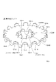
図4のA,B,Cは、導体接続ワッシャの構造を示す図である。Aは平面図、Bは側面図、CはAの4C−4C線での断面図である。図5は導体接続ワッシャの斜視図である。導体接続ワッシャ100は金属板からプレス加工により形成され、中央にワッシャ穴130を有する円形の板部110と、板部110の両面から交互に切り起こされ、各面に24個以上形成されたコンタクト突起121-n, 122-n (n=1, 2, …, N),123-m, 124-m (m=1, 2, …, M)(ただし、Nは16以上の整数、Mは8以上の整数)からなる。
4A, 4B, and 4C are diagrams showing the structure of the conductor connection washer. A is a plan view, B is a side view, and C is a cross-sectional view taken along
具体的には、それぞれの面の16個以上のコンタクト突起121-n, 122-n (n=1, 2, …, N)は、円形の板部の外周に沿って交互に互いに反対側の面から突出するよう形成され、それぞれの面の8個以上のコンタクト突起123-m, 124-m (m=1, 2, …, M)は、板部の中央に形成された穴の内周に沿って交互に互いに反対側の面から突出するよう形成される。穴の内周に沿って形成されたコンタクト突起123-m, 124-mと外接する円で規定されるワッシャ穴130は端子ヘッド210の径より大であり、カムブロック300の湾曲部の外形より小とされている。バスバー穴810も端子ヘッド210の径より大であり、導体接続ワッシャ100の外形より小とされている。ただし、後述の変形実施例のように、バスバー穴810及びワッシャ穴130としてバスバー800及び導体接続ワッシャ100の端辺から切り込んだスリットを形成すれば、スリットの幅は軸220が通ればよく、端子ヘッド210の径より小さくてもよい。
Specifically, the 16 or more contact protrusions 121-n, 122-n (n = 1, 2,..., N) on each surface are alternately opposite to each other along the outer periphery of the circular plate portion. 8 or more contact protrusions 123-m, 124-m (m = 1, 2,..., M) on each surface are formed so as to protrude from the surface, and the inner periphery of the hole formed in the center of the plate portion Are formed so as to protrude alternately from the surfaces opposite to each other. A
導体接続ワッシャ100は、接触抵抗を小さくする観点からは純銅に近い導電率を有することが望まれる。一方、バスバー800及び端子200よりも硬い銅合金を用いれば、コンタクト突起がバスバー800、端子基部230の導体表面に食い込むので接触抵抗を小さくしやすいが、銅合金の硬度を高くすると導電率が小さくなる。そこで、導体接続ワッシャ100としては、純銅の30〜50%の導電率を有する銅合金を使用するのが好ましい。特に、純銅の約40%の導電率を有する銅合金であれば、導電率の面でも機械的特性(硬度、弾性率)の面でもよい特性を有する。
The
なお、図4Aでは、コンタクト突起121-nと122-nを外周辺に沿って交互に、またコンタクト突起123-m、124-mを内周辺に沿って交互に設けたが(ただし、nは1以上N以下の整数、mは1以上M以下の整数)、板部110上の同じ位置(板の面に沿った2次元上の位置)で板部の一方と他方の両面にコンタクト突起を形成してもよい。このように同じ位置で両面に突起を形成するには、プレス加工でなく鋳造やブロックからの切削で形成する必要があり、あまり現実的でない。一方、図4Aのように板部110の外周辺及び内周辺に沿って交互に形成するのであれば、導体接続ワッシャ100を1枚の導電性板から型抜き加工で容易に製造できる。
In FIG. 4A, contact protrusions 121-n and 122-n are alternately provided along the outer periphery, and contact protrusions 123-m and 124-m are alternately provided along the inner periphery. 1 or more and an integer of N or less, m is an integer of 1 or more and M or less), and contact projections are formed on one side and the other side of the plate portion at the same position on the plate portion 110 (a two-dimensional position along the surface of the plate). It may be formed. Thus, in order to form protrusions on both sides at the same position, it is necessary to form them by casting or cutting from a block, not by pressing, which is not very realistic. On the other hand, if it forms alternately along the outer periphery and inner periphery of the
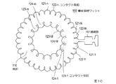
図6は、導体接続ワッシャを展開した(突起の方向を板の面と一致させた)平面図を示す。具体的には、型抜き過程S151、第1突起形成過程S152、裏返し過程S153、第2突起形成過程S154によって簡易に製造できる。型抜き過程S151は、1枚の導電性板を切断することで、すべてのコンタクト突起121-n、122-n、123-m、124-mの方向が板部110の面と一致する状態で、板部110とコンタクト突起121-n、122-n、123-m、124-mが一体的に形成された展開接続部材100’を形成する。第1突起形成過程S152は、展開接続部材100’の一部のコンタクト突起121-n、123-mを曲げることで、板110の一方の面のコンタクト突起121-n、123-mを形成する。裏返し過程S153は、一方の面のコンタクト突起が形成された展開接続部材100’を裏返す。第2突起形成過程S154は、第1突起形成過程で曲げなかったコンタクト突起122-n、124-mを、板部110の他方の面側に曲げる。このような方法によって図4Aに示した導体接続ワッシャは簡単に製造できる。また、コンタクト突起121-n、122-n、123-m、124-mの頂点は、型抜き過程S151で形成されるので、急峻にできる。各コンタクト突起の先端角度は好ましくは50〜70度である。また、第1突起形成過程S152と第2突起形成過程S154におけるコンタクト突起の板部110からの曲げ角度は60度より大きく90度より小さいことが好ましい。
FIG. 6 shows a plan view in which the conductor connection washer is developed (the direction of the protrusion is made coincident with the surface of the plate). Specifically, it can be easily manufactured by the die cutting process S151, the first protrusion forming process S152, the turning over process S153, and the second protrusion forming process S154. In the die cutting process S151, by cutting one conductive plate, the direction of all the contact protrusions 121-n, 122-n, 123-m, and 124-m coincides with the surface of the
図7は、バスバー800と端子基部230とで導体接続ワッシャを挟んだ状態の断面図である。上述のようにコンタクト突起121-n、122-n、123-m、124-m(図7においてはこれらを代表して120で示す)の方向と板部110の面とのなす角θを90度より小さくすれば、加わる荷重によってコンタクト突起121-n、122-n、123-m、124-mは、端子基部230やバスバー800の表面をワイピングし、90度の場合よりもさらに食い込むので良好な接触を実現しやすい。なお、コンタクト突起121-n、122-n、123-m、1234-mと板部110の面とのなす角θが小さすぎると、コンタクト突起が湾曲しやすくなり、荷重を加えても端子基部230やバスバー800に食い込みにくくなってしまう。従って、コンタクト突起121-n、122-n、123-m、124-mと板部110の面とのなす角θは60度より大きいことが望ましい。また、カムブロック300の逆止丘330を乗り越える際に荷重が最も大きくなり、乗り越えた後は荷重が少し小さくなるが、コンタクト突起121-n、122-n、123-m、124-mは少しではあるが撓むことや導体接続ワッシャ100全体の弾性によって、接続に必要な荷重は維持される。
FIG. 7 is a cross-sectional view of a state in which a conductor connection washer is sandwiched between the bus bar 800 and the
なお、前述の導体接続ワッシャ100の各コンタクト突起の先端は端子基部230と1点で接触するよう先端に向かって幅が狭くなる角度をなしているが、例えば図8に1つのコンタクト突起120の先端を示すように、端子基部230と2点で接触するよう先端部を2分しそれぞれ先端に向かって幅が狭くなる2つの接触部120a,120bを形成してもよい。2つの接触部120a,120bは同一面内に形成してもよいし、一方を導体接続ワッシャ100の半径方向内側に更に折り曲げて2つの接触点が半径方向にずれるよう形成してもよい。図8のコンタクト突起の構造は以下の変形実施例においても適用してよい。
Note that the tip of each contact projection of the above-described
本発明の導体接続ワッシャは上述のようにコンタクト突起を有するので、面同士が接触する場合よりも小さい荷重で確実に電気的接続できる。また、電流が端部に集中する特性を考慮してコンタクト突起を外周と内周に沿って配置しているので、少ないコンタクト突起で効率的に電流を流すことができる。つまり、コンタクト突起の数を少なくできるので、単にコンタクト突起を設ける場合よりもさらに小さい荷重で確実に電気的接続ができる。従って、本発明の導体接続ワッシャによれば、簡易にかつ確実に低い接触抵抗で2つの導体を電気的に接続できる。また、小さい荷重でよいので、カムブロックを用いるような加圧機構でも安定した接続を確保できる。 Since the conductor connection washer of this invention has a contact protrusion as mentioned above, it can be reliably electrically connected with a load smaller than the case where surfaces contact. In addition, since the contact protrusions are arranged along the outer periphery and the inner periphery in consideration of the characteristic that the current concentrates at the end portion, the current can be passed efficiently with few contact protrusions. That is, since the number of contact protrusions can be reduced, the electrical connection can be reliably performed with a smaller load than when the contact protrusions are simply provided. Therefore, according to the conductor connection washer of the present invention, the two conductors can be electrically connected easily and reliably with low contact resistance. Moreover, since a small load is sufficient, a stable connection can be ensured even with a pressurizing mechanism using a cam block.
本発明の接続機構は、本発明の導体接続ワッシャに適した機構であり、カムブロックを用いてバスバーと端子とで導体接続ワッシャを挟みつける構造である。従って、簡単にバスバーと端子とを接続できる。 The connection mechanism of the present invention is a mechanism suitable for the conductor connection washer of the present invention, and has a structure in which the conductor connection washer is sandwiched between the bus bar and the terminal using a cam block. Therefore, the bus bar and the terminal can be easily connected.
本発明の導体接続ワッシャの製造方法によれば、1枚の導電性の板から本発明の導体接続ワッシャを製造する方法であり、簡易な工程で導体接続ワッシャを製造できる。 According to the manufacturing method of the conductor connection washer of the present invention, the conductor connection washer of the present invention is manufactured from one conductive plate, and the conductor connection washer can be manufactured by a simple process.
[変形実施例]
図1の実施例ではカムブロックにより押圧する接続機構を実現する例を示したが、図9に示すようにカムを使用せず、ネジ締めにより押圧する接続機構としてもよい。即ち、この変形実施例では、端子200’の端子基部230から軸として機能するネジ240が直角に一体形成されており、そのネジ240に導体接続ワッシャ100とバスバー800が挿通され、バスバー800の上からワッシャ260を介して端子ヘッドとして機能するナット250により押圧する構成とされている。
[Modification]
Although the example which implement | achieves the connection mechanism pressed with a cam block was shown in the Example of FIG. 1, as shown in FIG. 9, it is good also as a connection mechanism pressed by screw fastening, without using a cam. That is, in this modified embodiment, a screw 240 functioning as a shaft is integrally formed at right angles from the
図10は導体接続ワッシャの変形実施例を展開した平面図である。導体接続ワッシャ100は接続部151を有している。接続部151は板部110の外周に一端が固着されている。接続部151は、コンタクト突起121-n、122-n、123-m、124-mが接触する端子基部とは異なる部品と接続するための手段である。例えば、接続部151は他の電気回路との接続のための圧着端子として使用できる。このように接続部を備えれば、電圧の測定などに便利である。この変形例の導体接続ワッシャは、図10のコンタクト突起を曲げることで作ることができる。
FIG. 10 is a plan view in which a modified embodiment of the conductor connection washer is developed. The
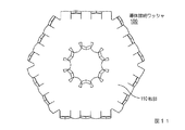
図11は導体接続ワッシャ100の他の変形実施例であり、図4Aとの差異は、外周が円でなく6角形とされ、6角形の各辺に沿ってコンタクト突起が形成されている。その他は図4Aと同じである。もちろん、外周は6角形に限らず、任意の多角形でよいことは明らかであるが、好ましくは5角以上の正多角形がよい。
FIG. 11 shows another modified embodiment of the
図12は導体接続ワッシャ100の更に他の変形実施例であり、図4Aとの差異は、中心のワッシャ穴130による内周が閉じておらず、ワッシャ穴130の径と同じ幅で中心から導体接続ワッシャ100の外周まで切り取られたスリット160が形成されていることである。この構成によれば、ワッシャ穴130の径を軸220の径より大とし、かつ端子ヘッド210の径より小とすることができる。図示してないが、図11に示した導体接続ワッシャ100においても、図12と同様にワッシャ穴130からその径と同じ幅で多角形の一辺まで切り取ってスリットを形成してもよい。
FIG. 12 shows still another modified embodiment of the
実験及びシミュレーション
図13は、2つのバスバーを直接ネジで締結したときの締め付け荷重と接触抵抗の関係を実測した結果である。荷重が大きい方が抵抗が小さくなる傾向があることが分かる。図14にシミュレーションに用いた2つのバスバー810,820と導体接続ワッシャ100の構成を示す。2つのバスバー810、820は導体接続ワッシャ100を挟んだ状態である。この図の例では、コンタクト突起の数を上下それぞれ20個としている。図15はバスバー820の垂直断面820Bを1V、バスバー810の垂直断面810Bを0Vとしたときの電圧の分布を等電圧線で示している。このような電圧の分布を解析して接触抵抗を求めた。
Experiment and Simulation FIG. 13 shows the results of actual measurement of the relationship between the tightening load and the contact resistance when two bus bars are directly tightened with screws. It can be seen that the resistance tends to decrease as the load increases. FIG. 14 shows the configuration of the two
図16のA,B,Cは、導体接続ワッシャ100の径(φ)が12mmの場合の抵抗値と片方の面のコンタクト突起の数(図では「歯数」と表示している)の関係をシミュレーションにより求めた結果を示している。図17のA,B,Cも同様のシミュレーション結果であり、導体接続ワッシャの径(φ)が18mmの場合の抵抗値と片方の面のコンタクト突起の数(歯数)の関係を示している。
16A, 16B, and 16C, the relationship between the resistance value when the diameter (φ) of the
図16Aと図17Aは板部110の厚さ(t)が0.5mmの場合、図16Bと図17Bは板部110の厚さ(t)が0.4mmの場合、図16Cと図17Cは板部110の厚さ(t)が0.3mmの場合を示している。また、図中のhはコンタクト突起の長さ、「全面」を示す線はバスバー810,820同士を直接全面接触させた場合の接触抵抗、「基準」を示す線は抵抗値が安定する(直線状となる)値を示し、全面接触の場合の1.5倍の値を示す線である。歯数が4、8、16は外周にのみコンタクト突起を付けた場合であって、1つの歯の接触している面積を仮想的に変えることで、どの歯数の場合もバスバー810、820と接触している面積の合計は同じにしている。歯数が24のときは外周に16個、内周に8個のコンタクト突起を付けた場合を示している。外周の16個のコンタクト突起は歯数が16個の場合と同じである。つまり、歯数が24個の場合は、バスバー810、820と接触している面積も増えている。また、各図の右端の位置(本来ならば歯数100の位置)に示した抵抗値は、外周のみに板厚と同じ幅のリング状の突起を付けた場合(外周全体が接触している場合)を示している。このときのバスバー810、820と接触している面積は歯数が16個の場合の2倍にしている。
16A and 17A show the case where the thickness (t) of the
図16のA,B,Cと図17のA,B,Cのすべての線で共通して、歯数が4、8、16のように増加すると抵抗値が小さくなっている。従って、接触面積が同じでもコンタクト突起の周の長さが長くなると接触抵抗が小さくなることが分かる。また、歯数が4、8、16の場合に比べると、歯数が24のところに段差がある。これは、内周にも突起を設けた効果だと考えられる。そして、歯数が24(外周に16個、内周に8個)の場合と外周全体を接触させた場合の抵抗値には大きな差がないことが分かる。また、このシミュレーションの全面接触は、理想的な全面接触の場合の結果を示している。しかし、現実には全面では接触しないので、実測で得られる接触抵抗は基準が示す抵抗値程度になると考えられる。従って、外周のコンタクト突起の数を面ごとに16個以上、内周のコンタクト突起の数を面ごとに8個以上とすることで、全面接触させ、ネジ締めなどで荷重を加えた場合に近い接触抵抗にできると考えられる。 In common with all the lines A, B, and C in FIG. 16 and A, B, and C in FIG. 17, the resistance value decreases as the number of teeth increases to 4, 8, and 16, for example. Therefore, it can be seen that even when the contact area is the same, the contact resistance decreases as the circumference of the contact protrusion increases. Further, there is a step at the position where the number of teeth is 24 compared to the case where the number of teeth is 4, 8, and 16. This is considered to be an effect of providing protrusions on the inner periphery. And it turns out that there is no big difference in the resistance value when the number of teeth is 24 (16 on the outer periphery and 8 on the inner periphery) and when the entire outer periphery is brought into contact. In addition, the entire contact in this simulation shows the result in the case of an ideal entire contact. However, since the actual contact is not made on the entire surface, the contact resistance obtained by actual measurement is considered to be about the resistance value indicated by the reference. Therefore, the number of contact protrusions on the outer periphery is 16 or more per surface, and the number of contact protrusions on the inner periphery is 8 or more per surface, which is close to the case where a load is applied by screwing or the like. It is thought that contact resistance can be achieved.
本発明は、主に比較的大きな電流が流れる導体同士の接続に利用することができる。 The present invention can be used mainly for connection between conductors through which a relatively large current flows.
100:導体接続ワッシャ
110:板部
121,122,123,124:コンタクト突起
130:ワッシャ穴
151:接続部
160:スリット
200,200’:端子
220:軸
230:端子基部
260:ワッシャ
310:スリット
320:斜面
330:逆止丘
800:バスバー
810:バスバー穴
900:電気部品
100: Conductor connection washer 110:
Claims (16)
中央にワッシャ穴を有する金属の板部と、
上記板部の外周に沿って、上記板部の両面にそれぞれ複数上記板部と一体形成されたコンタクト突起と、
上記ワッシャ穴の内周に沿って、上記板部の両面にそれぞれ複数上記板部と一体に形成されたコンタクト突起と、
を含み、上記板部に形成された上記コンタクト突起の合計数は24以上とされていることを特徴とする導体接続ワッシャ。 A conductor connection washer for electrically connecting two conductors,
A metal plate having a washer hole in the center;
A plurality of contact protrusions integrally formed with the plate portion on both sides of the plate portion along the outer periphery of the plate portion,
A plurality of contact protrusions integrally formed with the plate portion on both sides of the plate portion along the inner periphery of the washer hole,
And the total number of the contact protrusions formed on the plate portion is 24 or more.
上記端子は板状の端子基部と、上記端子基部から直角に延長された軸と、上記軸の先端に固定され、上記軸より大きい径を有する端子ヘッドとから構成されており、
上記軸に挿通されるワッシャ穴を有し、上記端子基部と隣接して配置された請求項1乃至12のいずれか記載の導体接続ワッシャと、
上記軸に挿通されるバスバー穴を有し、上記導体接続ワッシャと隣接して配置されたバスバーと、
上記軸に挿通される、上記端子ヘッドの径よりも小さい幅のスリットを有し、上記バスバーと上記端子ヘッドの間に挿入されたU字状のカムブロックと、
を含み、
上記カムブロックは、
U字状のカムブロックの開放端側の厚みは、上記導体接続ワッシャの非加圧時の厚さと上記バスバーの厚さの和と、上記端子基部と上記端子ヘッド間の距離との差より小とされており、
U字状の上記カムブロックの閉塞端側の厚みは、上記差より大とされており、
U字状の上記カムブロックの開放端側と閉塞端側との間に斜面が形成されていることを特徴とする接続機構。 A connection mechanism between a bus bar and a terminal of an electrical component,
The terminal comprises a plate-like terminal base, a shaft extending perpendicularly from the terminal base, and a terminal head fixed to the tip of the shaft and having a diameter larger than the shaft.
The conductor connection washer according to any one of claims 1 to 12, wherein the conductor connection washer has a washer hole inserted through the shaft, and is disposed adjacent to the terminal base.
A bus bar having a bus bar hole inserted through the shaft and disposed adjacent to the conductor connection washer;
A U-shaped cam block inserted between the bus bar and the terminal head, having a slit having a width smaller than the diameter of the terminal head, which is inserted through the shaft;
Including
The cam block
The open end side thickness of the U-shaped cam block is smaller than the difference between the thickness of the conductor connection washer when not pressed and the thickness of the bus bar and the distance between the terminal base and the terminal head. And
The thickness of the closed end side of the U-shaped cam block is larger than the above difference,
A connecting mechanism, wherein a slope is formed between an open end side and a closed end side of the U-shaped cam block.
上記端子は板状の端子基部と、上記端子基部から直角に延長形成されたネジと、上記ネジの先端部に取り付けられ、上記ネジより大きい径を有するナットとから構成されており、
上記ネジに挿通されるワッシャ穴を有し、上記端子基部と隣接して配置された請求項1乃至12のいずれか記載の導体接続ワッシャと、
上記ネジに挿通されるバスバー穴を有し、上記導体接続ワッシャと隣接して配置されたバスバーと、
を含み、
上記ナットにより上記バスバーを上記端子基部側に押圧して上記導体接続ワッシャのコンタクト突起を上記端子基部と上記バスバーとに接触させていることを特徴とする接続機構。 A connection mechanism between a bus bar and a terminal of an electrical component,
The terminal is composed of a plate-like terminal base, a screw formed at right angles from the terminal base, and a nut attached to the tip of the screw and having a larger diameter than the screw.
The conductor connection washer according to any one of claims 1 to 12, having a washer hole inserted through the screw, and disposed adjacent to the terminal base.
A bus bar having a bus bar hole inserted through the screw, and disposed adjacent to the conductor connection washer;
Including
A connection mechanism, wherein the bus bar is pressed toward the terminal base by the nut, and the contact protrusion of the conductor connection washer is brought into contact with the terminal base and the bus bar.
1枚の金属板を切断することで、すべての上記コンタクト突起が上記板部の面と一致する状態で、上記板部と上記コンタクト突起が一体的に形成された展開接続部材を形成する型抜き過程と、
上記展開接続部材の一部の上記コンタクト突起を曲げることで、上記板部の一方の面のコンタクト突起を形成する第1突起形成過程と、
一方の面のコンタクト突起が形成された上記展開接続部材を裏返す裏返し過程と、
上記第1突起形成過程で曲げなかった上記コンタクト突起を、上記板部の他方の面側に曲げる第2突起形成過程と
を有することを特徴とする導体接続ワッシャの製造方法。 It is a manufacturing method of the conductor connection washer according to claim 5,
Die-cutting that cuts a single metal plate to form a development connecting member in which the plate portion and the contact projection are integrally formed in a state where all the contact projections coincide with the surface of the plate portion. Process,
A first protrusion forming step of forming a contact protrusion on one surface of the plate portion by bending a part of the contact protrusion of the development connecting member;
An inside-out process of turning over the development connecting member formed with the contact projection on one side;
A method of manufacturing a conductor connection washer, comprising: a second protrusion forming step of bending the contact protrusion that has not been bent in the first protrusion forming process toward the other surface side of the plate portion.
Priority Applications (5)
| Application Number | Priority Date | Filing Date | Title |
|---|---|---|---|
| JP2011037975A JP2012009411A (en) | 2010-05-24 | 2011-02-24 | Conductor connection washer, connection mechanism using it and method of manufacturing conductor connection washer |
| KR1020110028724A KR101238188B1 (en) | 2010-05-24 | 2011-03-30 | Conductor-connecting washer, connection mechanism using the same, and method of manufacturing conductor-connecting washer |
| US13/083,518 US8303357B2 (en) | 2010-05-24 | 2011-04-08 | Conductor-connecting washer, connection mechanism using the same, and method of manufacturing conductor-connecting washer |
| EP11161826.0A EP2390946B1 (en) | 2010-05-24 | 2011-04-11 | Conductor-connecting washer, connection mechanism using the same, and method of manufacturing conductor-connecting washer |
| CN2011101446834A CN102332644A (en) | 2010-05-24 | 2011-04-11 | Conductor connects pad, the bindiny mechanism that uses it and conductor connection gasket piece making method |
Applications Claiming Priority (3)
| Application Number | Priority Date | Filing Date | Title |
|---|---|---|---|
| JP2010118277 | 2010-05-24 | ||
| JP2010118277 | 2010-05-24 | ||
| JP2011037975A JP2012009411A (en) | 2010-05-24 | 2011-02-24 | Conductor connection washer, connection mechanism using it and method of manufacturing conductor connection washer |
Publications (2)
| Publication Number | Publication Date |
|---|---|
| JP2012009411A true JP2012009411A (en) | 2012-01-12 |
| JP2012009411A5 JP2012009411A5 (en) | 2014-01-16 |
Family
ID=44246530
Family Applications (1)
| Application Number | Title | Priority Date | Filing Date |
|---|---|---|---|
| JP2011037975A Pending JP2012009411A (en) | 2010-05-24 | 2011-02-24 | Conductor connection washer, connection mechanism using it and method of manufacturing conductor connection washer |
Country Status (5)
| Country | Link |
|---|---|
| US (1) | US8303357B2 (en) |
| EP (1) | EP2390946B1 (en) |
| JP (1) | JP2012009411A (en) |
| KR (1) | KR101238188B1 (en) |
| CN (1) | CN102332644A (en) |
Cited By (8)
| Publication number | Priority date | Publication date | Assignee | Title |
|---|---|---|---|---|
| WO2014097896A1 (en) * | 2012-12-19 | 2014-06-26 | 三菱重工業株式会社 | Battery state monitoring device and battery module provided with same |
| JP2014122855A (en) * | 2012-12-21 | 2014-07-03 | Mitsubishi Heavy Ind Ltd | Battery state monitoring device and battery module including the same |
| WO2015052955A1 (en) * | 2013-10-09 | 2015-04-16 | 三菱電機株式会社 | Conductor connection structure and switch gear using same |
| WO2017175622A1 (en) * | 2016-04-08 | 2017-10-12 | 株式会社オートネットワーク技術研究所 | Electrical connection structure |
| JP2019029312A (en) * | 2017-08-03 | 2019-02-21 | 矢崎総業株式会社 | Electrode contact structure of bus bar module |
| EP3905446A1 (en) * | 2020-04-30 | 2021-11-03 | TE Connectivity Germany GmbH | Contact ring and contact system |
| JP2022081444A (en) * | 2020-11-19 | 2022-05-31 | ティーイー コネクティビティ ジャーマニー ゲゼルシャフト ミット ベシュレンクテル ハフツンク | Contact ring for high-level dynamic use |
| US11515680B2 (en) | 2020-04-30 | 2022-11-29 | Te Connectivity Germany Gmbh | Contact ring and contact system |
Families Citing this family (30)
| Publication number | Priority date | Publication date | Assignee | Title |
|---|---|---|---|---|
| US8092129B2 (en) * | 2006-04-21 | 2012-01-10 | Hubbell Incorporated | Bonding washer |
| DE102011014342A1 (en) * | 2011-03-18 | 2012-09-20 | GM Global Technology Operations LLC (n. d. Gesetzen des Staates Delaware) | Cable lug for connecting an electrical cable to a component of a motor vehicle |
| US8572909B2 (en) * | 2011-03-24 | 2013-11-05 | Solar Mounting Solutions, LLC | Flat roof solar racking system |
| US11022343B2 (en) | 2011-09-02 | 2021-06-01 | Pv Solutions, Llc | Mounting system for photovoltaic arrays |
| US10008974B2 (en) | 2011-09-02 | 2018-06-26 | Pv Solutions, Llc | Mounting system for photovoltaic arrays |
| US9142967B2 (en) | 2011-09-02 | 2015-09-22 | Pv Solutions, Llc | System for tracking and allocating renewable energy contributions to a modular renewable energy system |
| US9362634B2 (en) * | 2011-12-27 | 2016-06-07 | Perfectvision Manufacturing, Inc. | Enhanced continuity connector |
| CA2816502A1 (en) * | 2012-05-24 | 2013-11-24 | Cablofil, Inc. | Bonding clip |
| US8997336B2 (en) * | 2012-09-10 | 2015-04-07 | Renewable Energy Holdings, Llc | Air-tight and water-tight electrical bonding device |
| CN203232920U (en) * | 2012-12-25 | 2013-10-09 | 华广生技股份有限公司 | Battery conductive sheet and electronic device provided with movable battery conductive sheet |
| US9847521B2 (en) | 2012-12-25 | 2017-12-19 | Bionime Corporation | Conductive plate and an electronic device having the same |
| US9653194B2 (en) * | 2013-08-12 | 2017-05-16 | Te Connectivity Corporation | Low resistance insert |
| US9276521B2 (en) | 2014-01-16 | 2016-03-01 | JSI Equipment Solutions LLC | Clamp for solar panel array |
| US9520657B2 (en) * | 2014-07-31 | 2016-12-13 | Hubbell Incorporated | Electrical terminal |
| US10177401B2 (en) * | 2014-11-20 | 2019-01-08 | Qualcomm Incorporated | Method of establishing physical and electrical connections between a battery and a circuit |
| WO2016123357A2 (en) | 2015-01-28 | 2016-08-04 | Pv Solutions, Llc | Integrated electrical and mechanical photovoltaic array interconnection system |
| US10103468B2 (en) | 2015-03-06 | 2018-10-16 | Kd&E Solar, Llc. | Coating displacement electrical connecting device and related methods |
| USD782409S1 (en) | 2015-03-30 | 2017-03-28 | Johnson Controls Technology Company | Lithium ion battery cell with terminal washers |
| CN108885027A (en) * | 2015-12-09 | 2018-11-23 | 哈勃股份有限公司 | Engaging clip |
| USD823262S1 (en) * | 2017-05-10 | 2018-07-17 | Xerox Corporation | Earth plate |
| US10175631B2 (en) | 2017-05-10 | 2019-01-08 | Xerox Corporation | Earth plate with breakaway rotated tabs |
| USD832220S1 (en) | 2017-05-10 | 2018-10-30 | Xerox Corporation | Earth plate |
| USD867435S1 (en) | 2018-07-04 | 2019-11-19 | Innovelis, Inc. | Mount for electronic devices |
| US11149775B2 (en) * | 2017-11-22 | 2021-10-19 | Penn Engineering & Manufacturing Corp. | Easily removeable push-on spring nut |
| USD865727S1 (en) * | 2018-06-21 | 2019-11-05 | Innovelis, Inc. | Mount for electronic devices |
| USD905069S1 (en) | 2019-05-09 | 2020-12-15 | Innovelis, Inc. | Mount for electronic devices |
| USD905068S1 (en) | 2019-05-09 | 2020-12-15 | Innovelis, Inc. | Mount for electronic devices |
| CN111916926A (en) * | 2019-05-09 | 2020-11-10 | 博格华纳公司 | Electric connector and control valve comprising same |
| USD905067S1 (en) | 2019-05-09 | 2020-12-15 | Innovelis, Inc. | Mount for electronic devices |
| US11522303B1 (en) * | 2021-06-14 | 2022-12-06 | Te Connectivity Solutions Gmbh | Terminal post assembly for termination of electrical terminals without the need for tooling |
Citations (5)
| Publication number | Priority date | Publication date | Assignee | Title |
|---|---|---|---|---|
| JPS57164317U (en) * | 1981-04-09 | 1982-10-16 | ||
| JPS61189574U (en) * | 1985-05-17 | 1986-11-26 | ||
| JPS63259978A (en) * | 1987-04-16 | 1988-10-27 | 三菱電機株式会社 | Compression bonding terminal |
| JP2001097298A (en) * | 1999-09-29 | 2001-04-10 | Nec Eng Ltd | Grounding structure of electronic device |
| JP2004253311A (en) * | 2003-02-21 | 2004-09-09 | Toyota Motor Corp | Electrical connection member and connecting method of electrical connection member and battery pack |
Family Cites Families (17)
| Publication number | Priority date | Publication date | Assignee | Title |
|---|---|---|---|---|
| US1150745A (en) * | 1915-04-30 | 1915-08-17 | Thomas Washington Crozier | Nut-locking washer. |
| US1847689A (en) * | 1929-02-02 | 1932-03-01 | Shakeproof Lock Washer Co | Electrical connecter |
| US1911384A (en) * | 1930-07-14 | 1933-05-30 | Shakeproof Lock Washer Co | Lock washer |
| US1882089A (en) * | 1930-09-02 | 1932-10-11 | Shakeproof Lock Washer Co | Lock washer |
| US2559833A (en) | 1948-12-31 | 1951-07-10 | Domnic V Stellin | Lock washer |
| FR1586636A (en) | 1968-02-29 | 1970-02-27 | ||
| US4060301A (en) * | 1974-03-12 | 1977-11-29 | Beatty Albert W | Electrical connector for transmission line insulators |
| KR900003350Y1 (en) * | 1986-06-07 | 1990-04-20 | 금성기전 주식회사 | Anti-loosening screw |
| DE19600417A1 (en) | 1996-01-08 | 1997-07-17 | Sefag Ag | Contact element e.g. for storage battery pole |
| JP4274014B2 (en) | 2004-03-18 | 2009-06-03 | 日産自動車株式会社 | Conductive member and battery pack |
| JP3897029B2 (en) | 2004-03-30 | 2007-03-22 | 日産自動車株式会社 | Battery frame and battery pack |
| JP4543310B2 (en) | 2004-05-17 | 2010-09-15 | 株式会社デンソー | Electrode bonding method and electrode assembly |
| KR100696670B1 (en) * | 2005-09-05 | 2007-03-19 | 삼성에스디아이 주식회사 | Secondary battery module |
| US8092129B2 (en) * | 2006-04-21 | 2012-01-10 | Hubbell Incorporated | Bonding washer |
| JP5189758B2 (en) | 2006-11-30 | 2013-04-24 | 日産自動車株式会社 | Bipolar battery manufacturing apparatus and manufacturing method |
| KR200438876Y1 (en) | 2007-05-14 | 2008-03-07 | 이승철 | The washer breaking down an isolation |
| CN102197509B (en) | 2008-09-09 | 2014-11-26 | 江森自控帅福得先进能源动力系统有限责任公司 | Interconnection washer assembly for a battery assembly |
-
2011
- 2011-02-24 JP JP2011037975A patent/JP2012009411A/en active Pending
- 2011-03-30 KR KR1020110028724A patent/KR101238188B1/en not_active IP Right Cessation
- 2011-04-08 US US13/083,518 patent/US8303357B2/en not_active Expired - Fee Related
- 2011-04-11 CN CN2011101446834A patent/CN102332644A/en active Pending
- 2011-04-11 EP EP11161826.0A patent/EP2390946B1/en not_active Not-in-force
Patent Citations (5)
| Publication number | Priority date | Publication date | Assignee | Title |
|---|---|---|---|---|
| JPS57164317U (en) * | 1981-04-09 | 1982-10-16 | ||
| JPS61189574U (en) * | 1985-05-17 | 1986-11-26 | ||
| JPS63259978A (en) * | 1987-04-16 | 1988-10-27 | 三菱電機株式会社 | Compression bonding terminal |
| JP2001097298A (en) * | 1999-09-29 | 2001-04-10 | Nec Eng Ltd | Grounding structure of electronic device |
| JP2004253311A (en) * | 2003-02-21 | 2004-09-09 | Toyota Motor Corp | Electrical connection member and connecting method of electrical connection member and battery pack |
Cited By (13)
| Publication number | Priority date | Publication date | Assignee | Title |
|---|---|---|---|---|
| WO2014097896A1 (en) * | 2012-12-19 | 2014-06-26 | 三菱重工業株式会社 | Battery state monitoring device and battery module provided with same |
| US20150263396A1 (en) * | 2012-12-19 | 2015-09-17 | Mitsubishi Heavy Industries, Ltd. | Battery state monitoring device and battery module provided with same |
| JP2014122855A (en) * | 2012-12-21 | 2014-07-03 | Mitsubishi Heavy Ind Ltd | Battery state monitoring device and battery module including the same |
| US9337518B2 (en) | 2012-12-21 | 2016-05-10 | Mitsubishi Heavy Industries, Ltd. | Battery state monitoring device and battery module having the same |
| WO2015052955A1 (en) * | 2013-10-09 | 2015-04-16 | 三菱電機株式会社 | Conductor connection structure and switch gear using same |
| JP5989255B2 (en) * | 2013-10-09 | 2016-09-07 | 三菱電機株式会社 | Conductor connection structure and switchgear using the same |
| WO2017175622A1 (en) * | 2016-04-08 | 2017-10-12 | 株式会社オートネットワーク技術研究所 | Electrical connection structure |
| JP2017188386A (en) * | 2016-04-08 | 2017-10-12 | 株式会社オートネットワーク技術研究所 | Electrical connection structure |
| JP2019029312A (en) * | 2017-08-03 | 2019-02-21 | 矢崎総業株式会社 | Electrode contact structure of bus bar module |
| EP3905446A1 (en) * | 2020-04-30 | 2021-11-03 | TE Connectivity Germany GmbH | Contact ring and contact system |
| US11515680B2 (en) | 2020-04-30 | 2022-11-29 | Te Connectivity Germany Gmbh | Contact ring and contact system |
| JP2022081444A (en) * | 2020-11-19 | 2022-05-31 | ティーイー コネクティビティ ジャーマニー ゲゼルシャフト ミット ベシュレンクテル ハフツンク | Contact ring for high-level dynamic use |
| JP7206357B2 (en) | 2020-11-19 | 2023-01-17 | ティーイー コネクティビティ ジャーマニー ゲゼルシャフト ミット ベシュレンクテル ハフツンク | Contact rings for highly dynamic applications |
Also Published As
| Publication number | Publication date |
|---|---|
| US8303357B2 (en) | 2012-11-06 |
| KR20110128729A (en) | 2011-11-30 |
| EP2390946A2 (en) | 2011-11-30 |
| KR101238188B1 (en) | 2013-02-28 |
| EP2390946A3 (en) | 2012-01-11 |
| CN102332644A (en) | 2012-01-25 |
| US20110287644A1 (en) | 2011-11-24 |
| EP2390946B1 (en) | 2013-06-19 |
Similar Documents
| Publication | Publication Date | Title |
|---|---|---|
| JP2012009411A (en) | Conductor connection washer, connection mechanism using it and method of manufacturing conductor connection washer | |
| JP6532882B2 (en) | Electrical terminal with enhanced clamping force | |
| JP3343880B2 (en) | Terminal fitting | |
| WO2010024033A1 (en) | Terminal metal fitting and method of manufacturing terminal metal fitting | |
| JP5400318B2 (en) | Crimp terminal for aluminum wire | |
| JP2010198789A (en) | Terminal structure of crimp terminal | |
| US9543679B2 (en) | Electrical contact assembly | |
| JP2009283458A (en) | Crimp connection structure | |
| WO2017175622A1 (en) | Electrical connection structure | |
| JP6063678B2 (en) | Connecting member | |
| WO2020054390A1 (en) | Connection terminal and connector | |
| WO2009142278A1 (en) | Aluminum cable crimp terminal | |
| JP2015090739A (en) | Crimp terminal | |
| JP5498885B2 (en) | Electrode connection structure | |
| JP2015076235A (en) | Crimping terminal | |
| JP5151936B2 (en) | Terminal fitting and manufacturing method thereof | |
| JP4577194B2 (en) | Electrical connection terminal | |
| JP2014002977A (en) | Surface structure of conductive member, and washer and crimp terminal including surface structure | |
| CN209001304U (en) | A kind of precious metal electric brush | |
| JP5316860B2 (en) | Electric wire connection terminal for wire harness, repair electric wire and electric wire connection method | |
| JP3211235U (en) | Protective device | |
| JP5451655B2 (en) | Terminal connection structure and semiconductor device having the terminal connection structure | |
| JP5065065B2 (en) | Crimp terminal | |
| JP5733220B2 (en) | Terminal and electric wire with terminal | |
| JP2019032927A (en) | Bus bar, wire-equipped bus bar, and manufacturing method of wire-equipped bus bar |
Legal Events
| Date | Code | Title | Description |
|---|---|---|---|
| A521 | Request for written amendment filed |
Free format text: JAPANESE INTERMEDIATE CODE: A523 Effective date: 20131125 |
|
| A621 | Written request for application examination |
Free format text: JAPANESE INTERMEDIATE CODE: A621 Effective date: 20131125 |
|
| A977 | Report on retrieval |
Free format text: JAPANESE INTERMEDIATE CODE: A971007 Effective date: 20140820 |
|
| A131 | Notification of reasons for refusal |
Free format text: JAPANESE INTERMEDIATE CODE: A131 Effective date: 20140826 |
|
| A02 | Decision of refusal |
Free format text: JAPANESE INTERMEDIATE CODE: A02 Effective date: 20150106 |