JP2012006379A - Method for generatively manufacturing three-dimensional object with broaching element and method for generating corresponding data set - Google Patents
Method for generatively manufacturing three-dimensional object with broaching element and method for generating corresponding data set Download PDFInfo
- Publication number
- JP2012006379A JP2012006379A JP2011102781A JP2011102781A JP2012006379A JP 2012006379 A JP2012006379 A JP 2012006379A JP 2011102781 A JP2011102781 A JP 2011102781A JP 2011102781 A JP2011102781 A JP 2011102781A JP 2012006379 A JP2012006379 A JP 2012006379A
- Authority
- JP
- Japan
- Prior art keywords
- dimensional object
- cavity
- broaching member
- powder material
- manufacturing
- Prior art date
- Legal status (The legal status is an assumption and is not a legal conclusion. Google has not performed a legal analysis and makes no representation as to the accuracy of the status listed.)
- Withdrawn
Links
Images

Classifications
-
- B—PERFORMING OPERATIONS; TRANSPORTING
- B29—WORKING OF PLASTICS; WORKING OF SUBSTANCES IN A PLASTIC STATE IN GENERAL
- B29C—SHAPING OR JOINING OF PLASTICS; SHAPING OF MATERIAL IN A PLASTIC STATE, NOT OTHERWISE PROVIDED FOR; AFTER-TREATMENT OF THE SHAPED PRODUCTS, e.g. REPAIRING
- B29C64/00—Additive manufacturing, i.e. manufacturing of three-dimensional [3D] objects by additive deposition, additive agglomeration or additive layering, e.g. by 3D printing, stereolithography or selective laser sintering
- B29C64/30—Auxiliary operations or equipment
- B29C64/35—Cleaning
-
- B—PERFORMING OPERATIONS; TRANSPORTING
- B29—WORKING OF PLASTICS; WORKING OF SUBSTANCES IN A PLASTIC STATE IN GENERAL
- B29C—SHAPING OR JOINING OF PLASTICS; SHAPING OF MATERIAL IN A PLASTIC STATE, NOT OTHERWISE PROVIDED FOR; AFTER-TREATMENT OF THE SHAPED PRODUCTS, e.g. REPAIRING
- B29C64/00—Additive manufacturing, i.e. manufacturing of three-dimensional [3D] objects by additive deposition, additive agglomeration or additive layering, e.g. by 3D printing, stereolithography or selective laser sintering
- B29C64/10—Processes of additive manufacturing
- B29C64/141—Processes of additive manufacturing using only solid materials
- B29C64/153—Processes of additive manufacturing using only solid materials using layers of powder being selectively joined, e.g. by selective laser sintering or melting
-
- B—PERFORMING OPERATIONS; TRANSPORTING
- B29—WORKING OF PLASTICS; WORKING OF SUBSTANCES IN A PLASTIC STATE IN GENERAL
- B29C—SHAPING OR JOINING OF PLASTICS; SHAPING OF MATERIAL IN A PLASTIC STATE, NOT OTHERWISE PROVIDED FOR; AFTER-TREATMENT OF THE SHAPED PRODUCTS, e.g. REPAIRING
- B29C64/00—Additive manufacturing, i.e. manufacturing of three-dimensional [3D] objects by additive deposition, additive agglomeration or additive layering, e.g. by 3D printing, stereolithography or selective laser sintering
- B29C64/10—Processes of additive manufacturing
- B29C64/165—Processes of additive manufacturing using a combination of solid and fluid materials, e.g. a powder selectively bound by a liquid binder, catalyst, inhibitor or energy absorber
-
- B—PERFORMING OPERATIONS; TRANSPORTING
- B33—ADDITIVE MANUFACTURING TECHNOLOGY
- B33Y—ADDITIVE MANUFACTURING, i.e. MANUFACTURING OF THREE-DIMENSIONAL [3-D] OBJECTS BY ADDITIVE DEPOSITION, ADDITIVE AGGLOMERATION OR ADDITIVE LAYERING, e.g. BY 3-D PRINTING, STEREOLITHOGRAPHY OR SELECTIVE LASER SINTERING
- B33Y10/00—Processes of additive manufacturing
Abstract
Description
本発明は、三次元物体の生成的な製造方法及び対応データセットの生成方法に関する。 The present invention relates to a method for generating a three-dimensional object and a method for generating a corresponding data set.
特許文献1(DE 199 37 260 B4)は、三次元物体を生成的に製造する既知の方法と装置を開示する。この方法及び装置は、a)装置の支持体又は先に塗工された層に粉末材料を層状に塗工する工程と、b)層における上記三次元物体の断面に対応する位置にエネルギー放射により粉末材料を選択的に固化する工程と、c)上記三次元物体が完成するまで上記a)の塗工工程とb)の固化工程を繰り返す工程を含む。 Patent Document 1 (DE 199 37 260 B4) discloses a known method and apparatus for generatively producing a three-dimensional object. This method and apparatus comprises: a) a step of applying a powder material to a support of the apparatus or a previously applied layer, and b) energy radiation at a position corresponding to the cross section of the three-dimensional object in the layer. A step of selectively solidifying the powder material, and c) a step of repeating the coating step of a) and the solidification step of b) until the three-dimensional object is completed.
特許文献2(DE 295 06 716 U1)は、三次元物体を生成的に製造する既知の後処理方法を開示する。この方法では、残留粉末を除去するために、エアガンを用いて三次元物体を空気で吹き払う。 Patent document 2 (DE 295 06 716 U1) discloses a known post-processing method for producing a three-dimensional object in a generative manner. In this method, a three-dimensional object is blown off with air using an air gun in order to remove residual powder.
本発明は、三次元物体内における残留粉末の除去を簡易化する三次元物体の生成的な製造方法を提供することを目的とする。この三次元物体は、請求項1の特徴を含む方法と請求項10の特徴を有するデータセットの生成方法により達成される。また、従属項は本発明の更なる有利な具体例を規定する。 An object of the present invention is to provide a generative manufacturing method of a three-dimensional object that simplifies the removal of residual powder in the three-dimensional object. This three-dimensional object is achieved by a method comprising the features of claim 1 and a method for generating a data set having the features of claim 10. The dependent claims define further advantageous specific examples of the present invention.
本発明による三次元物体は、大きな負担なしに内部の残留粉末を放出できるという利点を有する。例えば細長い形状のブローチ加工部材は、少なくとも案内路を生成するために、三次元物体の通路又はある程度角度の付いた空洞における残留粉末の放出を可能にする。経路と空洞の全断面のそれぞれが徐々に露呈されるように粗粒の有無にかかわらず気流が加えられる場合には、この案内路は最小流量の流れを許可する。 The three-dimensional object according to the invention has the advantage that it can discharge the residual powder inside without significant burden. For example, an elongated shaped broaching member allows for the release of residual powder in the path of a three-dimensional object or in a somewhat angled cavity, at least to create a guide path. If airflow is applied with or without coarse grains so that each of the channel and the entire cross-section of the cavity is gradually exposed, this guideway allows the flow at the minimum flow rate.
ブローチ加工部材は、三次元物体の製造時に用いるデータの要素である。ブローチ加工部材は、空洞の内壁に接触しないように配置される。均一に延在する内壁の経路の形状である空洞において、ブローチ加工部材は経路の中立軸と等しく又は少なくとも略沿って延長する。三次元物体の各空洞に対して、分離したブローチ加工部材を設けてもよい。同様に、一つの空洞において二つの部材を配置してもよい。すなわち、ブローチ加工部材がブローチ加工に適した角度の地点を示す分岐点で分かれる場合があり、空洞における開口部の両方のどちらからでも取り出しできる。 The broached member is an element of data used when manufacturing a three-dimensional object. The broaching member is arranged so as not to contact the inner wall of the cavity. In a cavity that is in the form of a uniformly extending inner wall path, the broaching member extends at least approximately along the neutral axis of the path. A separate broaching member may be provided for each cavity of the three-dimensional object. Similarly, two members may be arranged in one cavity. That is, the broaching member may be divided at a branch point indicating a point of an angle suitable for broaching, and can be taken out from both of the openings in the cavity.
ブローチ部材は細長い形状を有し得るが、この形状に限られない。三次元物体用のデータセットの要素である各種類の幾何学的形状を用いることが可能であり、案内路を露呈できる。ブローチ加工部材は平坦な通路断面用の帯板形状、波形形状、又はらせん形状、又はこれらを組み合わせた形状を有し得る。従って、大きな角度が付いた空洞、通路、又は湾曲した通路のそれぞれから残留粉末を放出可能である。 The broach member may have an elongated shape, but is not limited to this shape. Each type of geometric shape that is an element of a data set for a three-dimensional object can be used, and a guideway can be exposed. The broached member may have a flat channel cross-sectional strip shape, a corrugated shape, or a spiral shape, or a combination thereof. Thus, residual powder can be released from each of the large angled cavities, passages, or curved passages.
本発明の更なる特徴及び目的は、以下の添付図面に基づく実施形態の説明から明らかになる。 Further features and objects of the present invention will become apparent from the following description of embodiments based on the accompanying drawings.
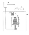
図1は、レーザ焼結装置として例示的に具体化された三次元物体3の製造装置の概略図を示す。 FIG. 1 shows a schematic view of an apparatus for manufacturing a three-dimensional object 3 exemplarily embodied as a laser sintering apparatus.
上記レーザ焼結装置は、上部に開口を有し、その内に支持体5を備えるフレーム1と、製造される三次元物体3を支持し、垂直移動可能な支持体5を備える。フレーム1は、上部2において造形領域6を囲む。好ましくは、フレーム1と支持体5は、レーザ焼結装置から取り外し可能且つ交換可能な代替フレームを形成する。支持体5は、固化される各層の上側が造形領域6の面に沿うように、少なくとも造形領域6の面の下方において支持体5を垂直移動するリフト機構4と連結する。 The laser sintering apparatus includes a frame 1 having an opening at an upper portion thereof and a support body 5 provided therein, and a support body 5 that supports a three-dimensional object 3 to be manufactured and is vertically movable. The frame 1 surrounds the modeling area 6 in the upper part 2. Preferably, the frame 1 and the support 5 form an alternative frame that is removable and replaceable from the laser sintering apparatus. The support 5 is connected to the lift mechanism 4 that vertically moves the support 5 at least below the surface of the modeling region 6 so that the upper side of each layer to be solidified follows the surface of the modeling region 6.
さらに、粉末材料11の層を塗工する塗工装置10が設けられる。粉末材料11として、全てのレーザ焼結可能な粉末が使用され得る。例えば、合成粉末、金属粉末、セラミック粉末、鋳物砂、及び複合材料粉末などが挙げられる。金属含有粉末状材料、任意の金属や合金を含む粉末材料、及び金属含有要素や非金属含有要素との混合物も考慮され得る。
Furthermore, a coating device 10 for coating a layer of the
塗工装置10は、粉末材料11の層がそれぞれ支持体5の上方及び最後に固化された層の上方に沿うように、造形領域6の上方における所定の高さに移動される。さらに上記装置は、偏向手段9により造形領域6における任意の位置に集中されるレーザビーム8、8’を発生するレーザ7形状の放射装置を備える。従って、レーザビーム8、8’は、製造される三次元物体3の断面に対応する位置に粉末材料11を選択的に固化できる。
The coating device 10 is moved to a predetermined height above the modeling region 6 so that the layer of the
レーザ焼結装置は、新たに塗工された粉末層を固化に必要な粉末材料11の加工温度近くに予熱するために、造形領域6の上方に加熱装置(不図示)を備える場合がある。
The laser sintering apparatus may include a heating device (not shown) above the modeling region 6 in order to preheat the newly coated powder layer near the processing temperature of the
参照符号100は、フレーム1、支持体5、及び塗工装置10が配置される筐体を示している。好ましくは、筐体100はレーザビーム8、8’導入用の入射口を上部領域に有する。また、好ましくは、筐体100は気密に形成され、その内部に不活性ガスを導入できる。さらに、本製造装置において制御装置40が提供される。この制御装置40によって、造形処理を行うため及びレーザ7によるエネルギーの影響を制御するために本製造装置が協調的に制御される。上記制御装置40は、三次元物体3を製造するために、三次元物体3の形状をCADデータなどで定義したデータセットを用いる。
本製造装置の操作では、最初に、第1粉末層の所望の厚さ単位で、支持体5の上側が造形領域6の面の下方に沿うまで、リフト機構4により支持体5が降下される。次に、塗工装置10によって第1の粉末材料11の層が支持体5上に塗工され、平坦化される。加熱装置が設けられる場合には、加熱装置を用いて最上部の粉末層11の全体的な温度を固化に必要な加工温度より数℃低い温度に予熱できる。その後、制御装置40は、固化される粉末材料11の層の位置に対して偏向レーザビーム8、8’が選択的に作用するように偏向手段9を制御する。従って、粉末材料11はそれらの位置で固化及び/又は焼結され、これにより三次元物体3が生成される。
In the operation of the manufacturing apparatus, first, the support 5 is lowered by the lift mechanism 4 until the upper side of the support 5 is below the surface of the modeling region 6 in a desired thickness unit of the first powder layer. . Next, a layer of the
次に、支持体5は、次層の所望の厚さ単位でリフト機構4により下降される。第2の粉末材料層は塗工装置10により塗工且つ平坦化され、さらにレーザビーム8、8’により選択的に固化される。これらの工程は所望の物体3が製造されるまで繰り返される。 Next, the support 5 is lowered by the lift mechanism 4 in a desired thickness unit of the next layer. The second powder material layer is coated and flattened by the coating apparatus 10 and further selectively solidified by the laser beams 8 and 8 '. These steps are repeated until the desired object 3 is manufactured.
図2は、図1の装置により製造される三次元物体3の断面図を示す。 FIG. 2 shows a cross-sectional view of a three-dimensional object 3 produced by the apparatus of FIG.
三次元物体3は、自身の下面において開口部14に開けた空洞13を有する。三次元物体3の製造中、空洞13内に延長し、開口部14を介して空洞13から取り出し可能なブローチ加工部材12が追加的に形成されるように、粉末材料11が固化される。図2に示す実施形態では、空洞13は、三次元物体3の上面において第2の開口部14’にも開けている。ブローチ加工部材12は第2の開口部14’を介して空洞13からも取り出し可能である。
The three-dimensional object 3 has a
このように、ブローチ加工部材12は、最終的な三次元物体3における固有の構成要素ではない。レーザ焼結処理により三次元物体3を完成させた後、ブローチ加工部材12が空洞13の開口部14から取り出され、案内路(pilot channel)が生成される。案内路は、レーザ焼結処理後に空洞13から取り除くべき残留粉末材料11の除去を簡略化する。ブローチ加工要素12が取り出された後、流体が開口部14、そして生成された案内路に加えられる。その結果、空洞13内の粉末材料11は除去され、空洞13の全断面が徐々に露呈される。例えば、流体は粗粒の有無に関わらず加圧空気であってもよく、三次元物体3の表面に沿って吹き付けられる。それにより粉末材料11は、ベンチュリノズル(Venturi-nozzle)と同様の動圧より、例えば開口部14から吸い込まれる。従って、上記加圧空気は他の開口部14’を介して空洞13内へ吸い込まれる。あるいは、加圧空気を開口部14内に直接吹き付けてもよい。その結果、残留粉末材料11が他の開口部14’から排出される。
Thus, the broaching
上述の流体は、加圧空気に限定されるものではなく、不活性ガスなどの他の気体、又は水や油などの液体であってもよい。 The fluid described above is not limited to pressurized air, and may be another gas such as an inert gas, or a liquid such as water or oil.
図示の実施形態において、ブローチ加工部材12は細長い形状である。しかし、本発明はこの形状に限られず、ブローチ加工要素は帯板形状、波形形状、らせん形状、又は他の適当な形状を有し得る。例えば、波形形状においては、正弦波、矩形波、又は鋸歯状波の波形に振動する。
In the illustrated embodiment, the broaching
ブローチ加工部材12の断面が、使用される粉末材料を考慮して適切に寸法決めされている場合、ブローチ加工部材12は折り曲げ可能であることが好ましい。これは、角度の付いた空洞からブローチ加工部材12を取り出す際に有利となる。例えば、取り出す際にブローチ加工部材12は伸縮され得る。
The broaching
同様に、ブローチ加工部材12を接合部と共に、又は複数のチェーンリンク(chain links)から成るチェーンとして形成することが考えられる。
Similarly, it is conceivable to form the broaching
ブローチ加工部材12は、ブローチ加工部材12を取り出す際に大量の粉末材料11を取り込むかかり(barbs)又は押付部材(共に不図示)を備える場合がある。
The broaching
図示の実施形態において、ブローチ加工部材12は、ブローチ加工部材12の把持を容易にする把持部材15を有する。しかしながら、把持部材15を設けなくてもよい。
In the illustrated embodiment, the broaching
図2から分かるように、ブローチ加工部材12は空洞13の内壁に接触しない。図示の実施形態において、空洞13は均一に延在する内壁を有し、通路13の形状となる。好ましくは、ブローチ加工部材12は実質的に通路13の中立軸に沿って延長する。従って、案内路の理想的な経路が確保される。しかしながら、ブローチ加工部材12の経路は、必ずしも通路13の中立軸に沿って延長する必要はない。
As can be seen from FIG. 2, the broaching
図2では、第2のブローチ加工部材12’が追加的に図示されている。第2のブローチ加工部材12’は、第1のブローチ加工部材12とは分離して形成され、第3の開口部14’’から取り出し可能である。
In FIG. 2, a second broaching member 12 'is additionally illustrated. The
上記実施形態には図示されていないが、ブローチ加工部材12は、ブローチ加工部材12が三次元物体3の空洞の異なる枝に進む分岐点を有する場合がある。好ましくは、ブローチ加工部材12は、三次元物体におけるブローチ加工部材の非分岐部分に結合する開口部から取り出される。
Although not shown in the above embodiment, the broaching
また、三次元物体3の一つの空洞13において、いくつかの分離したブローチ加工部材12を形成することが考えられる。同様に、分離したブローチ加工部材12は空洞13の異なる枝に部分的に延長することが考えられる。
It is also conceivable to form several
また、本発明は、三次元物体3のデータセットを生成する方法に関する。上記三次元物体3は、三次元物体3の生成的な製造方法を用いて製造される。例えば、上記データセットは三次元物体3のCADデータを含み、それによりレーザ焼結装置は三次元物体3を製造する。また、レーザ焼結装置は製造方法を実行する。レーザ焼結装置によって、粉末材料11は装置の支持体5又は先に塗工された層に繰り返し且つ層状に塗工される。粉末材料11はエネルギー放射8’により三次元物体3に対応する位置に固化される。三次元物体3は、自身の表面における開口部に開けた少なくとも一つの空洞13を有する。
The present invention also relates to a method for generating a data set of a three-dimensional object 3. The three-dimensional object 3 is manufactured using a generative manufacturing method for the three-dimensional object 3. For example, the data set includes CAD data of the three-dimensional object 3, whereby the laser sintering apparatus produces the three-dimensional object 3. In addition, the laser sintering apparatus executes a manufacturing method. By means of the laser sintering device, the
本発明による三次元物体3のデータセットを生成する方法は、以下のステップを含む。 The method for generating a data set of a three-dimensional object 3 according to the present invention includes the following steps.
初めに、完成した三次元物体の寸法及び形状を定義するデータセットが一般的な方法で生成される。例えば、これらは三次元物体3の通常のCADデータである。 Initially, a data set defining the dimensions and shape of the completed three-dimensional object is generated in a general manner. For example, these are normal CAD data of the three-dimensional object 3.
次に、ブローチ加工部材12の寸法と形状を定義するデータを用いてデータセットが完成する。ブローチ加工部材12は、空洞13内に延長し、開口部14を介して空洞13から取り出し可能である。それにより、ブローチ加工部材12はレーザ焼結装置により固有の三次元物体3とともに製造される。
Next, a data set is completed using data defining the dimensions and shape of the broached
本発明の技術的範囲は図示の実施形態に限定されず、提供される更なる変形や改良は請求項に規定する本発明の技術的範囲に属する。 The technical scope of the present invention is not limited to the illustrated embodiments, and further modifications and improvements provided belong to the technical scope of the present invention as defined in the claims.
例えば、本発明の製造装置はレーザ焼結に適用できるだけでなく、原料と粉末材料の各々が塗工される各層に用いられる粉体に基づいた生成方法の全てに適用可能である。そこでは、エネルギー放射などにより粉末が固化される。エネルギー放射は必ずしもレーザビーム8’である必要はなく、例えば電子ビームや粒子ビームであってもよい。さらに、例えばマスクなど、全表面に対する放射が可能である。エネルギー放射に換えて、粉末材料を選択的に接着する接着剤や結合剤を各々所望の位置に適用できる。 For example, the production apparatus of the present invention can be applied not only to laser sintering, but also to all production methods based on powder used for each layer on which a raw material and a powder material are applied. There, the powder is solidified by energy radiation or the like. The energy radiation does not necessarily have to be the laser beam 8 ', but may be, for example, an electron beam or a particle beam. Furthermore, radiation to the entire surface is possible, for example a mask. Instead of energy radiation, an adhesive or a binder that selectively adheres the powder material can be applied to each desired position.
Claims (10)
b)層における三次元物体(3)の断面に対応する位置に前記粉末材料(11)を選択的に固化し、
c)前記三次元物体(3)が完成するまで前記塗工と前記固化を繰り返すことを含む、三次元物体(3)の生成的な製造方法であって、
前記三次元物体(3)は、前記三次元物体(3)の表面における開口部(14)に開けた少なくとも一つの空洞(13)を有し、
前記粉末材料(11)は、前記空洞(13)内に延長し、前記開口部(14)を介して前記空洞から取り出し可能なブローチ加工部材(12)が形成されるように固化されることを特徴とする製造装置を用いた三次元物体(3)の生成的な製造方法。 a) The powder material (11) is applied in layers to the support (5) of the production apparatus or the previously applied layer,
b) selectively solidifying said powder material (11) at a position corresponding to the cross section of the three-dimensional object (3) in the layer;
c) a generative production method of a three-dimensional object (3) comprising repeating the coating and the solidification until the three-dimensional object (3) is completed,
The three-dimensional object (3) has at least one cavity (13) opened in an opening (14) in the surface of the three-dimensional object (3);
The powder material (11) extends into the cavity (13) and is solidified to form a broaching member (12) that can be removed from the cavity through the opening (14). A generative production method of a three-dimensional object (3) using the production apparatus characterized.
前記空洞(13)内の前記粉末材料(11)が除去されるように前記開口部(14)と前記案内路に流体を適用することをさらに含む請求項1に記載の製造方法。 After the three-dimensional object (3) is completed, the broaching member (12) is taken out from the opening (14) of the cavity (13) to form a guide path,
The manufacturing method according to claim 1, further comprising applying a fluid to the opening (14) and the guide path so that the powder material (11) in the cavity (13) is removed.
前記三次元物体(3)の表面における開口部(14)に開けた少なくとも一の空洞(13)を備える完成した三次元物体(3)の形状を定義するデータセットを生成し、
前記空洞(13)内に延長し、前記開口部(14)を介して前記空洞(13)から取り出し可能なブローチ加工部材(12)の形状を定義するデータにより前記データセットを補足することを特徴とするデータセットの生成方法。 The powder material (11) is repeatedly applied in layers to the support (5) of the production apparatus or the previously applied layer, and the powder material (11) is solidified at a position corresponding to the three-dimensional object (3). A method of generating a data set of a three-dimensional object (3) manufactured by a generative manufacturing method,
Generating a data set defining the shape of the completed three-dimensional object (3) comprising at least one cavity (13) opened in an opening (14) in the surface of the three-dimensional object (3);
Supplementing the data set with data defining the shape of a broaching member (12) extending into the cavity (13) and removable from the cavity (13) through the opening (14) How to create a dataset.
Applications Claiming Priority (2)
| Application Number | Priority Date | Filing Date | Title |
|---|---|---|---|
| DE102010019447A DE102010019447A1 (en) | 2010-05-05 | 2010-05-05 | A method for generatively producing a three-dimensional object with reamers and method for creating a corresponding dataset |
| DE102010019447.6 | 2010-05-05 |
Publications (1)
| Publication Number | Publication Date |
|---|---|
| JP2012006379A true JP2012006379A (en) | 2012-01-12 |
Family
ID=44484026
Family Applications (1)
| Application Number | Title | Priority Date | Filing Date |
|---|---|---|---|
| JP2011102781A Withdrawn JP2012006379A (en) | 2010-05-05 | 2011-05-02 | Method for generatively manufacturing three-dimensional object with broaching element and method for generating corresponding data set |
Country Status (4)
| Country | Link |
|---|---|
| US (1) | US20120107496A1 (en) |
| EP (1) | EP2384882A1 (en) |
| JP (1) | JP2012006379A (en) |
| DE (1) | DE102010019447A1 (en) |
Cited By (1)
| Publication number | Priority date | Publication date | Assignee | Title |
|---|---|---|---|---|
| JP2014065180A (en) * | 2012-09-25 | 2014-04-17 | Brother Ind Ltd | Three-dimensional shaping apparatus and three-dimensional shaping data creation program |
Families Citing this family (27)
| Publication number | Priority date | Publication date | Assignee | Title |
|---|---|---|---|---|
| WO2014165310A2 (en) | 2013-03-15 | 2014-10-09 | 3D Systems, Inc. | Improved powder distribution for laser sintering systems |
| DE102013224693A1 (en) * | 2013-12-02 | 2015-06-03 | Eos Gmbh Electro Optical Systems | Method for the accelerated production of objects by means of generative production |
| CA2952633C (en) | 2014-06-20 | 2018-03-06 | Velo3D, Inc. | Apparatuses, systems and methods for three-dimensional printing |
| EP3028839A1 (en) * | 2014-12-01 | 2016-06-08 | Siemens Aktiengesellschaft | A method for manufacturing an object by laser sintering and a laser sintering device for manufacturing the object |
| US10040235B2 (en) * | 2014-12-30 | 2018-08-07 | Wobbleworks, Inc. | Extrusion device for three-dimensional drawing |
| GB201502086D0 (en) * | 2015-02-09 | 2015-03-25 | Rolls Royce Plc | Methods of manufacturing and cleaning |
| GB201509580D0 (en) * | 2015-06-03 | 2015-07-15 | Rolls Royce Plc | Manufacture of component with cavity |
| US10786966B2 (en) | 2015-10-05 | 2020-09-29 | Raytheon Technologies Corporation | Additive manufactured conglomerated powder removal from internal passages |
| CN108367498A (en) | 2015-11-06 | 2018-08-03 | 维洛3D公司 | ADEPT 3 D-printings |
| US10207454B2 (en) | 2015-12-10 | 2019-02-19 | Velo3D, Inc. | Systems for three-dimensional printing |
| US20170197284A1 (en) * | 2016-01-13 | 2017-07-13 | United Technologies Corporation | Method for removing partially sintered powder from internal passages in electron beam additive manufactured parts |
| US10434573B2 (en) | 2016-02-18 | 2019-10-08 | Velo3D, Inc. | Accurate three-dimensional printing |
| DE102016205147A1 (en) | 2016-03-29 | 2017-10-05 | Eos Gmbh Electro Optical Systems | Machining tool and method for its production by means of a generative layering process |
| EP3492244A1 (en) | 2016-06-29 | 2019-06-05 | VELO3D, Inc. | Three-dimensional printing system and method for three-dimensional printing |
| US11691343B2 (en) | 2016-06-29 | 2023-07-04 | Velo3D, Inc. | Three-dimensional printing and three-dimensional printers |
| US10661341B2 (en) | 2016-11-07 | 2020-05-26 | Velo3D, Inc. | Gas flow in three-dimensional printing |
| US20180186081A1 (en) | 2017-01-05 | 2018-07-05 | Velo3D, Inc. | Optics in three-dimensional printing |
| US10682704B2 (en) | 2017-01-24 | 2020-06-16 | General Electric Company | Material extraction tool |
| US10442003B2 (en) | 2017-03-02 | 2019-10-15 | Velo3D, Inc. | Three-dimensional printing of three-dimensional objects |
| US20180281283A1 (en) | 2017-03-28 | 2018-10-04 | Velo3D, Inc. | Material manipulation in three-dimensional printing |
| US10654065B2 (en) | 2017-08-11 | 2020-05-19 | General Electric Company | Cleaning fixtures and methods of cleaning components using cleaning fixtures |
| US11001002B2 (en) * | 2017-08-24 | 2021-05-11 | The Regents Of The University Of California | Powder bed additive manufacturing method of fabricating a porous matrix |
| FR3070288B1 (en) | 2017-08-31 | 2019-09-06 | Safran Landing Systems | METHOD FOR CLEARING PIPES IN PARTS OBTAINED BY ADDITIVE MANUFACTURING |
| US10272525B1 (en) | 2017-12-27 | 2019-04-30 | Velo3D, Inc. | Three-dimensional printing systems and methods of their use |
| US10144176B1 (en) | 2018-01-15 | 2018-12-04 | Velo3D, Inc. | Three-dimensional printing systems and methods of their use |
| EP3511093A1 (en) * | 2018-01-16 | 2019-07-17 | Siemens Aktiengesellschaft | Method of removing an excess material from a cavity, additive manufacturing method and part |
| WO2020065650A1 (en) * | 2018-09-26 | 2020-04-02 | Stratasys Ltd. | Automated 3d-printing of hollow objects |
Family Cites Families (29)
| Publication number | Priority date | Publication date | Assignee | Title |
|---|---|---|---|---|
| US3874463A (en) * | 1972-03-29 | 1975-04-01 | Charles L Hicks | Means for boring parallel holes |
| DE2643525A1 (en) * | 1976-09-28 | 1978-03-30 | Kloth Senking Eisen Metall | CORE FOR THE MANUFACTURING OF THIN-CHANNELED CASTINGS |
| US6209420B1 (en) * | 1994-03-16 | 2001-04-03 | Baker Hughes Incorporated | Method of manufacturing bits, bit components and other articles of manufacture |
| US5482659A (en) * | 1994-12-22 | 1996-01-09 | United Technologies Corporation | Method of post processing stereolithographically produced objects |
| DE29506716U1 (en) | 1995-04-21 | 1995-06-22 | Eos Electro Optical Syst | Device for post-processing an object made of a powdery or granular material |
| US5849238A (en) * | 1997-06-26 | 1998-12-15 | Ut Automotive Dearborn, Inc. | Helical conformal channels for solid freeform fabrication and tooling applications |
| US6355086B2 (en) * | 1997-08-12 | 2002-03-12 | Rolls-Royce Corporation | Method and apparatus for making components by direct laser processing |
| US6391251B1 (en) * | 1999-07-07 | 2002-05-21 | Optomec Design Company | Forming structures from CAD solid models |
| DE19937260B4 (en) | 1999-08-06 | 2006-07-27 | Eos Gmbh Electro Optical Systems | Method and device for producing a three-dimensional object |
| US6623687B1 (en) * | 1999-08-06 | 2003-09-23 | Milwaukee School Of Engineering | Process of making a three-dimensional object |
| US6955023B2 (en) * | 2000-12-13 | 2005-10-18 | Kevin Chaite Rotheroe | Unitary metal structural member with internal reinforcement |
| AU2002360464A1 (en) * | 2001-12-03 | 2003-06-17 | Memgen Corporation | Miniature rf and microwave components and methods for fabricating such components |
| US7372616B2 (en) * | 2001-12-06 | 2008-05-13 | Microfabrica, Inc. | Complex microdevices and apparatus and methods for fabricating such devices |
| JP2003214300A (en) * | 2002-01-18 | 2003-07-30 | Toyota Motor Corp | Manufacturing method of injector nozzle |
| US7033160B2 (en) * | 2002-05-28 | 2006-04-25 | 3D Systems, Inc. | Convection cooling techniques in selective deposition modeling |
| WO2005097476A2 (en) * | 2004-04-02 | 2005-10-20 | Z Corporation | Methods and apparatus for 3d printing |
| US7521652B2 (en) * | 2004-12-07 | 2009-04-21 | 3D Systems, Inc. | Controlled cooling methods and apparatus for laser sintering part-cake |
| US20070126157A1 (en) * | 2005-12-02 | 2007-06-07 | Z Corporation | Apparatus and methods for removing printed articles from a 3-D printer |
| US20070163114A1 (en) * | 2006-01-13 | 2007-07-19 | General Electric Company | Methods for fabricating components |
| WO2008103985A2 (en) * | 2007-02-23 | 2008-08-28 | The Exone Company, Llc | Replaceable build box for three dimensional printer |
| EP1973189B1 (en) * | 2007-03-20 | 2012-12-05 | Nuvotronics, LLC | Coaxial transmission line microstructures and methods of formation thereof |
| US8070473B2 (en) * | 2008-01-08 | 2011-12-06 | Stratasys, Inc. | System for building three-dimensional objects containing embedded inserts, and method of use thereof |
| US9789540B2 (en) * | 2008-02-13 | 2017-10-17 | Materials Solutions Limited | Method of forming an article |
| US8061142B2 (en) * | 2008-04-11 | 2011-11-22 | General Electric Company | Mixer for a combustor |
| US20100021638A1 (en) * | 2008-07-28 | 2010-01-28 | Solidscape, Inc. | Method for fabricating three dimensional models |
| JP4404947B1 (en) * | 2009-02-12 | 2010-01-27 | 株式会社松浦機械製作所 | Three-dimensional structure manufacturing method |
| US20110017581A1 (en) * | 2009-07-23 | 2011-01-27 | Keith Bryan Hardin | Z-Directed Switch Components for Printed Circuit Boards |
| CA2788249A1 (en) * | 2009-12-30 | 2011-07-07 | Beat Lechmann | Intergrated multi-material implants and methods of manufacture |
| DE102010020418A1 (en) * | 2010-05-12 | 2011-11-17 | Eos Gmbh Electro Optical Systems | Apparatus and method for the generative production of a three-dimensional object with construction panel boundary |
-
2010
- 2010-05-05 DE DE102010019447A patent/DE102010019447A1/en not_active Withdrawn
-
2011
- 2011-05-02 JP JP2011102781A patent/JP2012006379A/en not_active Withdrawn
- 2011-05-02 US US13/098,726 patent/US20120107496A1/en not_active Abandoned
- 2011-05-03 EP EP11164573A patent/EP2384882A1/en not_active Withdrawn
Cited By (1)
| Publication number | Priority date | Publication date | Assignee | Title |
|---|---|---|---|---|
| JP2014065180A (en) * | 2012-09-25 | 2014-04-17 | Brother Ind Ltd | Three-dimensional shaping apparatus and three-dimensional shaping data creation program |
Also Published As
| Publication number | Publication date |
|---|---|
| DE102010019447A1 (en) | 2011-11-10 |
| EP2384882A1 (en) | 2011-11-09 |
| US20120107496A1 (en) | 2012-05-03 |
Similar Documents
| Publication | Publication Date | Title |
|---|---|---|
| JP2012006379A (en) | Method for generatively manufacturing three-dimensional object with broaching element and method for generating corresponding data set | |
| JP6409079B2 (en) | Method for additive manufacturing and keyway support | |
| RU2311984C2 (en) | Casting method and equipment for performing the same | |
| JP6475766B2 (en) | Method for additive manufacturing and support around it | |
| JP6420855B2 (en) | Method for additive manufacturing | |
| CN107052336B (en) | Method for additive manufacturing and support with powder removal port | |
| CN105710377B (en) | Composite additive manufacturing method using composite additive manufacturing features for composite components | |
| JP6412180B2 (en) | Method for additive manufacturing and leading edge support | |
| JP6547262B2 (en) | Three-dimensional forming apparatus and three-dimensional forming method | |
| US9901983B2 (en) | Method of applying multiple materials with selective laser melting on a 3D article | |
| US20140349132A1 (en) | Method for manufacturing a compact component, and component that can be produced by means of the method | |
| CN102240806A (en) | Device and method for generative manufacturing of a three dimensional object with construction area limit | |
| CN108971486B (en) | Method and apparatus for growing compression chambers to relieve powder loading on a growing part in powder-based additive manufacturing | |
| CN109328121B (en) | Method for additive manufacturing and multi-purpose powder removal component | |
| JP6937587B2 (en) | Casting method including step-by-step core parts | |
| EP3096907B1 (en) | Nanoparticle enhancement for additive manufacturing | |
| EP3238913B1 (en) | Additively manufactured components including channels | |
| US11584068B2 (en) | Additive manufacturing systems and methods including louvered particulate containment wall | |
| JP2022046610A (en) | Method for additionally manufacturing three-dimensional object | |
| JP6711868B2 (en) | Continuous additive manufacturing of high pressure turbines | |
| EP3315227A1 (en) | Method of manufacturing metal articles | |
| CN108580891A (en) | A kind of rapid three dimensional printing forming method | |
| JP6878364B2 (en) | Movable wall for additional powder floor | |
| US20210362267A1 (en) | Method of manufacturing metal articles | |
| CN108943324A (en) | A kind of 3D printing powder bonding method based on water-soluble effect |
Legal Events
| Date | Code | Title | Description |
|---|---|---|---|
| A300 | Application deemed to be withdrawn because no request for examination was validly filed |
Free format text: JAPANESE INTERMEDIATE CODE: A300 Effective date: 20140805 |