JP2012004643A - Video recording device, video recording system and video recording method - Google Patents
Video recording device, video recording system and video recording method Download PDFInfo
- Publication number
- JP2012004643A JP2012004643A JP2010135042A JP2010135042A JP2012004643A JP 2012004643 A JP2012004643 A JP 2012004643A JP 2010135042 A JP2010135042 A JP 2010135042A JP 2010135042 A JP2010135042 A JP 2010135042A JP 2012004643 A JP2012004643 A JP 2012004643A
- Authority
- JP
- Japan
- Prior art keywords
- video data
- recording
- abnormality
- receiving
- network camera
- Prior art date
- Legal status (The legal status is an assumption and is not a legal conclusion. Google has not performed a legal analysis and makes no representation as to the accuracy of the status listed.)
- Pending
Links
Images


Landscapes
- Television Signal Processing For Recording (AREA)
- Studio Devices (AREA)
- Signal Processing For Digital Recording And Reproducing (AREA)
Abstract
Description
本発明は録画装置、録画システム、録画方法及びプログラムに関し、特に、映像データのバッファリング制御と記録制御とに用いて好適な技術に関する。 The present invention relates to a recording apparatus, a recording system, a recording method, and a program, and more particularly, to a technique suitable for use in buffering control and recording control of video data.
従来、一般的には、映像解析により物体の移動や追加などの変化をイベントとして検出する場合に、小さな変化により誤検出しないように、映像の変化量が閾値を超えて一定期間継続する場合に物体の移動や追加を検知してイベントとして通知する。そして、映像解析の結果に基づいて録画制御を行う際には、イベントの通知を受けて録画を開始または終了する。例えば、特許文献1には、映像解析による画像変化の検出に基づいた録画の制御方法が開示されている。
Conventionally, in general, when a change such as movement or addition of an object is detected as an event by video analysis, the change amount of the video exceeds a threshold value and continues for a certain period so as not to be erroneously detected due to a small change. Detects movement or addition of an object and notifies it as an event. When recording control is performed based on the result of video analysis, the recording is started or ended upon receiving an event notification. For example,
しかしながら、特許文献1に開示された技術では、このイベントの通知がされた後に録画を開始するため、イベントによる結果は録画されるが、それよりも前のイベントが発生した原因は録画できなかった。
However, in the technique disclosed in
そこで、この問題を解決するために、イベントの通知よりも遡って録画できるように、録画装置が最新から一定期間の映像データを常にメモリにバッファリングしておく。そして、イベントの通知を受けると、メモリにバッファリングしている映像データを記録媒体に記録し、続けて以降の映像データを記録する技術が知られている。このとき、映像解析でイベントを検出した場合に、検出時刻から解析処理で用いた期間を差し引いてその時刻をイベントの開始時刻として特定する。例えば、特許文献2には、解析処理で用いた期間を自動的に遡って再生を開始する方法が開示されている。 Therefore, in order to solve this problem, the recording device always buffers video data for a certain period from the latest in the memory so that recording can be performed retroactively from event notification. When receiving an event notification, a technique for recording video data buffered in a memory on a recording medium and subsequently recording subsequent video data is known. At this time, when an event is detected by video analysis, the time used in the analysis process is subtracted from the detection time to specify the time as the event start time. For example, Patent Document 2 discloses a method of automatically starting reproduction by tracing back a period used in analysis processing.
しかしながら、常に映像データをバッファリングする従来技術では、さらに録画をする装置に必要となるメモリ容量が対象のカメラの数とバッファリングの期間に比例して増加するという問題がある。 However, in the conventional technique in which video data is always buffered, there is a problem that the memory capacity required for a recording apparatus further increases in proportion to the number of target cameras and the buffering period.
本発明は前述の問題点に鑑み、異常発生イベントの通知を受ける前からの映像を記録できるようにするとともに、メモリの容量を抑えることができるようにすることを目的としている。 In view of the above-described problems, an object of the present invention is to enable recording of a video before receiving a notification of an abnormality occurrence event and to reduce the capacity of a memory.
本発明の録画装置は、映像を撮影して異常を解析するネットワークカメラとネットワークを介して接続され、前記ネットワークカメラから送信された映像データを記録する録画装置であって、前記ネットワークカメラから映像データを受信するとともに、異常の解析情報を受信する通信手段と、前記通信手段により受信された映像データを一時的に記憶部に記憶する記憶制御手段と、前記記憶部に一時的に記憶された映像データを記録媒体に記録する記録手段とを備え、前記通信手段は、前記解析情報として異常の候補を検出した旨の通知を受信することにより、前記映像データの受信を開始し、前記記録手段は、前記通信手段が前記解析情報として異常を検出した旨の通知を受信することにより、前記記憶部に一時的に記憶された映像データの記録を開始することを特徴とする。 The recording apparatus of the present invention is a recording apparatus that is connected to a network camera that captures an image and analyzes an abnormality through a network and records the image data transmitted from the network camera, and the image data from the network camera. Communication means for receiving abnormality analysis information, storage control means for temporarily storing video data received by the communication means in a storage section, and video temporarily stored in the storage section Recording means for recording data on a recording medium, and the communication means starts receiving the video data by receiving a notification that an abnormality candidate has been detected as the analysis information, and the recording means When the communication means receives notification that the abnormality is detected as the analysis information, the video data temporarily stored in the storage unit is received. Characterized in that to start the recording.
本発明によれば、異常がもたらされた原因が発生した時点から録画をすることができるとともに、多数のネットワークカメラ装置から録画を行う場合においてもメモリの容量を削減することができる。 According to the present invention, recording can be performed from the time when the cause of the abnormality occurs, and the capacity of the memory can be reduced even when recording is performed from a large number of network camera devices.
以下に、本発明の好ましい実施形態について、添付の図面に基づいて詳細に説明する。
(第1の実施形態)
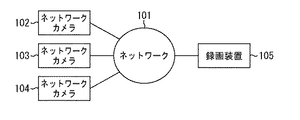
図1は、本実施形態に係る録画システムの全体構成例を示す図である。
本実施形態に係る録画システムは、映像をネットワークに配信するネットワークカメラ102〜104と、ネットワークカメラ102〜104からの映像を録画する録画装置105と、これらの装置をつなぐネットワーク101とから構成されている。
Hereinafter, preferred embodiments of the present invention will be described in detail with reference to the accompanying drawings.
(First embodiment)
FIG. 1 is a diagram illustrating an example of the overall configuration of a recording system according to the present embodiment.
The recording system according to the present embodiment includes
なお、図1には、ネットワークカメラを3台備えた例について示しているが、ネットワークカメラは少なくとも1台存在するものとし、ネットワークカメラは何台あってもよい。また、録画装置105も複数台あってもよい。さらに、ネットワークカメラ102〜104は、時系列な電子データを生成する装置であり、さらに映像以外の音声データや温度計などのセンサーの時系列なデータを送信する装置であってもよい。本実施形態では、映像システムの主たる用途は監視業務であり、録画装置105は、数十台から数百台のネットワークカメラからの映像を録画することができる。
Although FIG. 1 shows an example in which three network cameras are provided, it is assumed that there is at least one network camera and any number of network cameras may be provided. Further, a plurality of recording devices 105 may be provided. Furthermore, the
以下、図2〜図6を参照しながら、本実施形態による録画装置105の映像バッファリング制御方法について説明する。
図2(A)は、図1で示したネットワークカメラ102の機能構成例を示すブロック図である。以下の説明では、複数のネットワークカメラを代表してネットワークカメラ102の構成について説明する。
図2(A)において、撮像部201は、レンズや撮像素子などから構成されている。また、撮像部201は、映像を撮影するだけではなく、撮影制御部203の制御により撮影を行う際のズーム倍率やフォーカス、絞り、シャッタースピード、ゲイン、赤外線撮影などといった撮影設定を変更することができる。駆動部202は、撮像部201を載せてパン・チルト方向に回転することができる雲台を備えており、撮影制御部203の制御により雲台を移動させることによって、雲台に載せた撮像部201の撮影方向や撮影姿勢を変更する。
Hereinafter, the video buffering control method of the recording apparatus 105 according to the present embodiment will be described with reference to FIGS.
FIG. 2A is a block diagram illustrating a functional configuration example of the
In FIG. 2A, the
撮影制御部203は、撮像部201の撮影設定や駆動部202の撮影方向や撮影姿勢を制御する。記憶部205は、映像解析のプログラム及びその設定情報を記憶するメモリであり、さらに、外部センサーを解析するプログラム及びその設定情報をも記憶している。通信部206は、外部の装置とネットワーク101を介して通信するためのものである。全体制御部204は、ネットワークカメラ102全体を制御するものであり、外部センサー部207は、ネットワークカメラ102に人感センサーやドアセンサーなどの機器を接続するためのものである。
The
通信部206が、外部の装置からネットワークカメラ102を操作するコマンドを受信した場合は、全体制御部204によりコマンドを解析し、解析結果に基づいて撮影制御部203は撮像部201の撮影設定や、駆動部202の撮影方向などを制御する。そして、全体制御部204は、撮像部201で生成した映像データを記憶部205に一時保存し、撮像部201の撮影設定の情報や駆動部202の撮影姿勢の情報などを映像データに追加する。そして、通信部206から外部の装置に送信する。
When the
また、全体制御部204は、記憶部205に記憶している映像解析のプログラム及びその設定情報を読み出し、記憶部205に一時保存した映像データに対して映像解析を行う。そして、通信部206より解析結果の情報を送信する。さらに、全体制御部204は、記憶部205に記憶している外部センサーを解析するプログラム及びその設定情報を読み出し、外部センサー部207に入力された情報を解析する。そして、通信部206により解析結果の情報を送信する。
Further, the
図2(B)は、図1に示した録画装置105の機能構成例を示すブロック図である。
図2(B)において、通信部251は、他の装置と通信を行うためのものである。一時記憶部253は、RAM(Random Access Memory)などから構成されており、プログラムやデータを一時記憶する。
FIG. 2B is a block diagram illustrating an example of a functional configuration of the recording device 105 illustrated in FIG.
In FIG. 2B, a communication unit 251 is for communicating with other devices. The temporary storage unit 253 includes a RAM (Random Access Memory) and the like, and temporarily stores programs and data.
記録部254は、複数のネットワークカメラから受信したそれぞれの映像データをハードディスクや光ディスク、メモリカードなどの記録媒体255に記録する。また、記録部254は、時刻や通知に応じた各録画により、ネットワークカメラに要求する映像の画像サイズ、フレームレート、画質、撮影方向などの録画設定一覧の情報を記録媒体255に記録する。さらに、通信部251により複数のネットワークカメラから受信したそれぞれの映像解析結果や外部センサーの解析結果などの解析情報を記録媒体255に記録する。また、各ネットワークカメラの設置位置や用途などの利用者が定めたメタ情報をも記録媒体255に記録する。なお、記録媒体255には、前述したデータ以外に、映像解析のプログラム及びその設定情報が記録されている。
The
全体制御部252は、CPU(Central Processing Unit)を備えており、録画装置105全体の制御と演算処理とを行う。通信部251がネットワークカメラから映像データを受信すると、全体制御部252は、映像データを一時記憶部253に一時的に記憶するよう記憶制御し、記録部254により映像解析のプログラム及びその設定情報を記録媒体255から読み出す。そして、全体制御部252は、一時記憶部253に記憶した映像データに対して映像解析を行い、その解析結果を記録部254により記録媒体255に記録する。また、全体制御部252は、詳細は後述するが、異常候補を検出した旨の通知を受けると、ネットワークカメラに対して映像の配信を要求するコマンドを作成する。
The overall control unit 252 includes a CPU (Central Processing Unit), and performs overall control and arithmetic processing of the recording apparatus 105. When the communication unit 251 receives video data from the network camera, the overall control unit 252 performs storage control so that the video data is temporarily stored in the temporary storage unit 253, and the
また、外部の表示装置から、記録している映像データの再生コマンドを通信部251が受信した場合は、全体制御部252により再生コマンドを解析し、再生する映像データの撮影元のネットワークカメラと撮影時刻と再生方法とを特定する。そして、記録媒体255に該当する映像データが記録されているか否かを確認し、記録されている場合には、記録部254により映像データを読み出して通信部251から再生コマンドの送信元の表示装置に映像データを送信する。
When the communication unit 251 receives a playback command for recorded video data from an external display device, the overall control unit 252 analyzes the playback command, and shoots with the network camera that is the source of the video data to be played back. Specify the time and playback method. Then, it is confirmed whether or not the video data corresponding to the recording medium 255 is recorded. If the video data is recorded, the video data is read by the
図4は、ネットワークカメラ102の全体制御部204により実施される映像解析の処理手順の一例を示すフローチャートである。なお、図4に示す各処理は、全体制御部204の制御により行われる。
図4において、撮影を開始すると、ステップS401において、撮像部201により映像フレームを取得する。そして、全体制御部204は、記憶部205に記憶されている映像解析のプログラムを読み出し、アルゴリズムに従って1つ前の映像フレームの解析結果を用いて映像を解析して変化量を算出する。
FIG. 4 is a flowchart illustrating an example of a video analysis processing procedure performed by the
In FIG. 4, when shooting is started, a video frame is acquired by the
次に、ステップS402において、ステップS401の解析により得られる変化量が閾値を超えているか否かを判断する。この判断の結果、閾値を超えている場合は、ステップS404において、通信部206により、接続している録画装置105に対して異常候補の開始を通知する。そして、ステップS405において、閾値を超えた時刻の情報を記憶部205に記憶する。
Next, in step S402, it is determined whether or not the amount of change obtained by the analysis in step S401 exceeds a threshold value. If the threshold is exceeded as a result of this determination, in step S404, the
次に、ステップS407において、映像フレームの解析により得られる変化量が閾値を超えているか否かを再び判断する。この判断の結果、閾値を超えている場合は、ステップS408において、ステップS405で記憶した時刻からの経過時間が、所定の継続期間を超えているか否かを判断する。この判断の結果、継続期間を超えていない場合は、ステップS406において、撮像部201により次の新しい映像フレームを取得し、ステップS401と同様に映像解析を行う。そして、ステップS407に戻る。
Next, in step S407, it is determined again whether or not the amount of change obtained by analyzing the video frame exceeds a threshold value. If it is determined that the threshold value is exceeded, it is determined in step S408 whether or not the elapsed time from the time stored in step S405 exceeds a predetermined duration. If the result of this determination is that the duration has not been exceeded, the next new video frame is acquired by the
一方、ステップS408の判断の結果、継続期間を超えた場合は、ステップS409において、通信部206により、接続している録画装置105に対して異常状態の開始を通知する。次に、ステップS411において、撮像部201から次の新しい映像フレームを取得し、ステップS401と同様に映像解析を行う。そして、ステップS412において、映像フレームの解析により得られる変化量が閾値を超えているか否かを判断する。この判断の結果、閾値を超えている場合は、ステップS411へ戻る。一方、ステップS412の判断の結果、閾値を超えていない場合は、ステップS410において、通信部206により、接続している録画装置105に対して異常状態の終了を通知する。
On the other hand, as a result of the determination in step S408, if the duration is exceeded, in step S409, the
一方、ステップS407の判断の結果、変化量が閾値を超えていない場合は、ステップS414において、通信部206により、接続している録画装置105に対して異常候補の検出が終了したことを通知する。そして、ステップS415において、ステップS405で記憶した時刻情報を破棄する。一方、ステップS402の判断の結果、変化量が閾値を超えていない場合は、ステップS403において、映像解析を終了するか否かを判断する。この判断の結果、映像解析を終了しない場合は、ステップS401に戻り、映像フレームの取得から処理を繰り返す。一方、ステップS403の判断の結果、映像解析を終了する場合は、そのまま処理を終了する。
On the other hand, as a result of the determination in step S407, if the change amount does not exceed the threshold value, in step S414, the
ここで、ステップS404の処理では、さらに現在のパン位置、チルト位置及びズーム位置の情報を記憶部205に記憶し、事前に記憶部205に記憶されていたパン位置、チルト位置及びズーム位置に駆動部202と撮像部201とを制御してもよい。さらに、ステップS414の処理では、ステップS404で記憶部205に記憶したパン位置、チルト位置及びズーム位置に駆動部202と撮像部201とを制御するようにしてもよい。
Here, in the process of step S404, information on the current pan position, tilt position, and zoom position is further stored in the
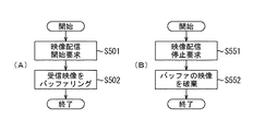
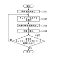
図5(A)は、録画装置105がネットワークカメラ102から異常候補の開始の通知を受信したときの処理手順の一例を示すフローチャートである。
図4のステップS404により異常候補の開始の通知がなされ、その通知を受信すると処理を開始する。そして、ステップS501において、記録部254は、記録媒体255に記録されている録画設定一覧の情報から送信元であるネットワークカメラ102の録画設定を抽出する。そして、全体制御部252は、抽出した録画設定より映像配信の開始コマンドを生成し、通信部251により送信元であるネットワークカメラ102に送信する。次に、ステップS502において、ネットワークカメラ102から、通信部251により送信したコマンドに対応する映像データを受信し、全体制御部252は、一時記憶部253に映像データを逐次記憶する。そして、処理を終了する。
FIG. 5A is a flowchart illustrating an example of a processing procedure when the recording apparatus 105 receives a notification of the start of an abnormality candidate from the
Notification of the start of the abnormality candidate is made in step S404 in FIG. 4, and processing is started when the notification is received. In step S501, the
図5(B)は、録画装置105がネットワークカメラ102から異常候補の終了の通知を受信したときの処理手順の一例を示すフローチャートである。
図4のステップS414により異常候補の終了の通知がなされ、その通知を受信すると処理を開始する。そして、ステップS551において、全体制御部252は、配信を停止するコマンドを作成し、通信部251により送信元であるネットワークカメラ102に送信する。そして、ステップS552において、全体制御部252は、一時記憶部253に記憶されたネットワークカメラ102からの映像データを破棄し、処理を終了する。
FIG. 5B is a flowchart illustrating an example of a processing procedure when the recording apparatus 105 receives a notification of the end of an abnormal candidate from the
In step S414 in FIG. 4, notification of the end of the abnormality candidate is made, and when the notification is received, the process is started. In step S551, the overall control unit 252 creates a command for stopping distribution, and transmits the command to the
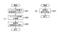
図6(A)は、録画装置105がネットワークカメラ102から異常状態の開始の通知を受信したときの処理手順の一例を示すフローチャートである。
図4のステップS409により異常状態の開始の通知がなされ、その通知を受信すると処理を開始する。そして、ステップS601において、記録部254は、一時記憶部253に記憶されている映像データを記録媒体255にコピーする。次に、ステップS602において、全体制御部252は、コピーされた映像データを一時記憶部253から破棄する。そして、ステップS603において、通信部251によりネットワークカメラ102から映像データを受信し、記録部254によりその映像データを記録媒体255に記録し、処理を終了する。
FIG. 6A is a flowchart illustrating an example of a processing procedure when the recording apparatus 105 receives a notification of an abnormal state start from the
The notification of the start of the abnormal state is made in step S409 in FIG. 4, and the processing is started when the notification is received. In step S <b> 601, the
図6(B)は、録画装置105がネットワークカメラ102から異常状態の終了の通知を受信したときの処理手順の一例を示すフローチャートである。
図4のステップS410により異常状態の終了の通知がなされ、その通知を受信すると処理を開始する。そして、ステップS651において、記録部254は、送信元のネットワークカメラ102から配信されている映像データの記録を停止し、処理を終了する。
FIG. 6B is a flowchart illustrating an example of a processing procedure when the recording apparatus 105 receives a notification of the abnormal state end from the
In step S410 in FIG. 4, a notice of the end of the abnormal state is given, and processing is started when the notice is received. In step S651, the
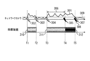
図3は、ネットワークカメラ102の通知動作、及びその通知を受けた録画装置105の動作の一例を示す図である。
図3において、横軸はネットワークカメラ102及び録画装置105の動作の時間軸を示している。また、301〜309がネットワークカメラ102の動作及び状態を示し、310〜312が録画装置105の動作及び状態を示している。本実施形態のネットワークカメラ102は、前述したように、異常状態の開始及び終了を通知するだけではなく、異常候補の開始及び終了も通知する。
FIG. 3 is a diagram illustrating an example of the notification operation of the
In FIG. 3, the horizontal axis indicates the time axis of the operation of the
301は、ネットワークカメラ102の全体制御部204により行われる映像解析によって得られる変化量の変化を示している。309は、図4のステップS402、S407及びS412の判断に用いた閾値を示している。308は、図4のステップS408の判断に用いた継続期間を示している。図3に示す例では、時刻T1、T3に、変化量が閾値を上回り異常候補の開始がネットワークカメラ102より録画装置105に通知されている。そして、時刻T2、T5に、変化量が閾値を下回り、異常候補の終了がネットワークカメラ102より録画装置105に通知されている。なお、302、304は、異常候補の開始を通知したことを示し、303、307は、異常候補の終了を通知したことを示している。
また、時刻T4の段階では、変化量が閾値を上回り、かつ継続期間に到達したため、異常状態の開始がネットワークカメラ102より録画装置105に通知されている。そして、時刻T5に、変化量が閾値を下回ったため、異常状態の終了がネットワークカメラ102より録画装置105に通知されている。なお、305は、異常状態の開始を通知したことを示し、306は、異常状態の終了を通知したことを示している。
Also, at the stage of time T4, since the amount of change has exceeded the threshold and has reached the duration, the
一方、録画装置105側は、時刻T1に異常候補の開始の通知を受け、時刻T2に異常候補の終了の通知を受けている。310は、時刻T1〜T2の期間にネットワークカメラ102から映像データを取得して一時記憶部253に記憶(バッファリング)している期間を示している。図3に示す例では、時刻T1で異常候補の開始の通知を受けてから継続期間が経過する前の時刻T2に異常候補の終了の通知を受けたため、バッファリングした映像データが時刻T2に一時記憶部253より破棄される。
On the other hand, the recording apparatus 105 receives a notification of the start of the abnormality candidate at time T1, and receives a notification of the end of the abnormality candidate at time T2.
また、録画装置105は、時刻T3に異常候補の開始の通知を再び受けており、311は、ネットワークカメラ102から映像データを取得して一時記憶部253にバッファリングしている期間を示している。そして、バッファリングを継続している間に、継続期間が経過した時刻T4で異常状態の開始の通知を受けている。312は、記録部254により時刻T3からバッファリングした映像データを記録媒体255に記録するとともに、引き続き受信した映像データを記録媒体255に記録している期間を示している。そして、録画装置105は、時刻T4で異常状態の終了の通知及び異常候補の終了の通知を受け、記録部254による映像データの記録処理を終了する。
In addition, the recording apparatus 105 has received the notification of the start of the abnormality candidate again at time T3, and 311 indicates a period during which video data is acquired from the
以上のように本実施形態によれば、異常候補の開始の通知を受けてから異常状態の開始の通知を受けた場合には、異常候補の開始の通知があった時刻の映像データから記録媒体255に記録することができる。また、異常候補の開始があったのみで、異常候補の終了の通知を受けた場合には、異常候補の期間の映像データは記録媒体255に記録されない。 As described above, according to the present embodiment, when a notification of the start of an abnormal state is received after receiving the notification of the start of the abnormality candidate, the recording medium is obtained from the video data at the time when the notification of the start of the abnormality candidate is received. 255 can be recorded. In addition, when the abnormality candidate is only started and a notification of the completion of the abnormality candidate is received, the video data of the abnormality candidate period is not recorded on the recording medium 255.
前述のように本実施形態においては、図4のステップS404及びS414において、変化量が閾値を上回ったまたは下回った場合にも通知している。これは、映像解析により異常の候補が検出されたことを録画装置105に通知するためである。 As described above, in the present embodiment, notification is also given when the amount of change exceeds or falls below the threshold in steps S404 and S414 in FIG. This is to notify the recording apparatus 105 that a candidate for abnormality has been detected by video analysis.
なお、録画装置105は、ネットワークカメラ102との接続を確立した直後に録画設定に基づいた映像配信要求を行ってもよい。この場合、異常候補または異常状態の開始の通知を受けておらず、バッファリング及び録画の必要がない場合は、受信した映像フレームを直ちに一時記憶部253から破棄する。そして、図5(A)のステップS501では、受信した映像の破棄を停止するように制御する。また、図5(B)のステップS551では、受信した映像データの破棄を開始するように制御する。
Note that the recording device 105 may make a video distribution request based on the recording settings immediately after establishing a connection with the
(第2の実施形態)
本実施形態では、以下、図7〜図11を参照しながら、第1の実施形態で示したバッファリング制御方法から異なるバッファリング制御方法へ切り替える処理について説明する。本実施形態における録画システム、ネットワークカメラ及び録画装置の構成については、それぞれ図1及び図2と同様であるため、説明は省略する。
(Second Embodiment)
In the present embodiment, a process for switching from the buffering control method shown in the first embodiment to a different buffering control method will be described below with reference to FIGS. The configurations of the recording system, the network camera, and the recording apparatus in this embodiment are the same as those in FIGS.
図7は、録画装置105がネットワークカメラ102からの映像データを一時記憶部253に記憶するバッファリング制御の処理手順の一例を示すフローチャートである。なお、図7に示す各処理は、全体制御部252の制御により行われる。本実施形態では、対象とするネットワークカメラ102との接続が確立したとき、またはネットワークカメラ102の記録部254による映像データの記録を停止したときに、一時記憶部253へのバッファリングを開始する。
FIG. 7 is a flowchart illustrating an example of a buffering control processing procedure in which the recording apparatus 105 stores video data from the
以上のような条件を満たすと処理を開始し、ステップS701において、記録部254は、記録媒体255に記録されている録画設定一覧情報から対象のネットワークカメラ用のバッファリング期間及びその他の録画設定の情報を読み出す。そして、ステップS702において、全体制御部252は、録画設定の情報から映像配信の開始コマンドを生成してネットワークカメラ102に送信する。
When the above conditions are satisfied, the process starts. In step S701, the
次に、ステップS703において、通信部251によりネットワークカメラ102から映像データを受信し、映像フレームを抽出する。次に、ステップS704において、全体制御部252は、映像フレームの受信時刻とバッファリング期間の設定値とから映像フレームの破棄時刻を算出する。そして、ステップS705において、破棄時刻の情報とともに映像フレームを一時記憶部253に記憶(バッファリング)する。次に、ステップS706において、映像の録画を開始したり、もしくはネットワークカメラ102との接続が切断されたりしたことにより、バッファリングを停止するか否かを判断する。この判断の結果、バッファリングを継続する場合は、ステップS703に戻り、処理を繰り返す。一方、ステップS706の判断の結果、バッファリングを停止する場合は、そのまま処理を終了する。
In step S703, the communication unit 251 receives video data from the
図8(A)は、バッファリングした映像データ(映像フレーム)を一時記憶部253から破棄する処理手順の一例を示すフローチャートである。なお、図8(A)に示す処理は全体制御部252の制御により行われ、タイマー等を用いて一定間隔の時間毎に実施される。また、複数のネットワークカメラから映像フレームを受信している場合は、ネットワークカメラ毎に処理を行う。 FIG. 8A is a flowchart illustrating an example of a processing procedure for discarding buffered video data (video frame) from the temporary storage unit 253. Note that the process shown in FIG. 8A is performed under the control of the overall control unit 252, and is performed at regular intervals using a timer or the like. When video frames are received from a plurality of network cameras, processing is performed for each network camera.
まず、ステップS801において、一時記憶部253に記憶している映像フレームのうち、破棄時刻が最も古い映像フレームを抽出する。そして、ステップS802において、破棄時刻を経過しているか否かを判断する。この判断の結果、破棄時刻を経過していない場合は、処理を終了し、破棄時刻を経過している場合は、ステップS803において、映像フレームを一時記憶部253から破棄する。 First, in step S801, the video frame with the oldest discard time is extracted from the video frames stored in the temporary storage unit 253. In step S802, it is determined whether the discard time has elapsed. As a result of this determination, if the discard time has not elapsed, the process is terminated. If the discard time has elapsed, the video frame is discarded from the temporary storage unit 253 in step S803.
図8(B)は、録画装置105がバッファリング制御方法を選択する処理手順の一例を示すフローチャートである。以下の説明では、第1の実施形態で説明した図5(A)のバッファリング制御方法を第1のバッファリング制御方法と称し、本実施形態で図7に示したバッファリング制御方法を第2のバッファリング制御方法と称す。なお、図8(B)に示す処理は全体制御部252の制御により行われ、録画装置105がネットワークカメラとの接続を確立したとき、または諸条件の変化によりバッファリング制御方法を見直すときにネットワークカメラ毎に実施される。 FIG. 8B is a flowchart illustrating an example of a processing procedure for the recording apparatus 105 to select a buffering control method. In the following description, the buffering control method of FIG. 5A described in the first embodiment is referred to as a first buffering control method, and the buffering control method shown in FIG. This is called the buffering control method. The process shown in FIG. 8B is performed under the control of the overall control unit 252, and when the recording apparatus 105 establishes a connection with the network camera or when the buffering control method is reviewed due to changes in various conditions, the network This is done for each camera.
まず、ステップS851において、設定や録画状態やその履歴から対象のネットワークカメラが第1のバッファリング制御方法の条件を満たすか否かを判断する。なお、第1のバッファリング制御方法の条件については後述する。この判断の結果、条件を満たす場合は、ステップS852において、対象のネットワークカメラからの映像データを第1のバッファリング制御方法で処理するよう設定する。一方、ステップS851の判断の結果、条件を満たさない場合は、ステップS853において、対象のネットワークカメラからの映像データを第2のバッファリング制御方法で処理するよう設定する。 First, in step S851, it is determined whether the target network camera satisfies the conditions of the first buffering control method from the setting, the recording state, and the history. The conditions for the first buffering control method will be described later. If the result of this determination is that the condition is satisfied, in step S852, the video data from the target network camera is set to be processed by the first buffering control method. On the other hand, if it is determined in step S851 that the condition is not satisfied, in step S853, the video data from the target network camera is set to be processed by the second buffering control method.
第1のバッファリング制御方法を用いた録画処理では、異常を検出した時点からではなく異常の兆候があった時点から録画することができる。一方、異常候補または異常状態の開始及び終了が逐次通知されるため、通知が頻繁にある場合は、映像配信の開始及び終了の処理によるタイムラグが大きくなることがある。さらに、ネットワークカメラから異常候補または異常状態が頻繁に通知されると、録画装置105からの映像配信要求または映像配信終了要求が頻発する。したがって、ネットワークにおいて遅延したり輻輳したりして通知や要求のネットワークパケットが紛失したり、パケットを紛失したことによりパケットを再送するために必要な期間の録画を逃したりする可能性がある。 In the recording process using the first buffering control method, recording can be performed not from the time of detecting the abnormality but from the time when there is a sign of abnormality. On the other hand, since the start and end of abnormal candidates or abnormal states are notified sequentially, the time lag due to the start and end processing of video distribution may become large when there are frequent notifications. Furthermore, when a candidate for abnormality or an abnormal state is frequently notified from the network camera, a video distribution request or a video distribution end request from the recording device 105 frequently occurs. Therefore, there is a possibility that the network packet of notification or request is lost due to delay or congestion in the network, or that recording for a period necessary for resending the packet is missed due to loss of the packet.
一方、第2のバッファリング制御方法を用いた録画処理では、異常を検出した時点から一定期間遡った時点で異常の兆候が含まれているか否かが不確定である。また、常にバッファリングを行っているため、使用するメモリの容量が録画するネットワークカメラに比例して増大する。ところが、映像を常時受信しているため、異常候補または異常状態が頻繁に通知されてもタイムラグが発生しない。また、映像配信要求を逐次行う必要がないため、ネットワークにおいて遅延したり輻輳したりすることを低減できる。 On the other hand, in the recording process using the second buffering control method, it is uncertain whether or not an abnormality sign is included at a time point that is a certain period after the abnormality is detected. Further, since buffering is always performed, the capacity of the memory to be used increases in proportion to the network camera that records. However, since the video is constantly received, no time lag occurs even if the abnormal candidate or abnormal state is frequently notified. In addition, since it is not necessary to sequentially perform video distribution requests, it is possible to reduce delays and congestion in the network.
次に、第1のバッファリング制御方法を用いる条件について説明する。図9は、記録媒体255に記録されている各ネットワークカメラの映像解析の履歴の一例を示す図である。
図9において、映像解析の履歴には、それぞれ変化量が閾値を上回った旨の通知回数、変化量が閾値を上回るが異常状態ではない期間(変化時間)、異常状態の開始の通知回数、及び異常状態の継続時間(異常時間)が含まれている。そして、これらの値は時間帯ごとの平均であり、変化時間及び異常時間は秒単位である。
Next, conditions for using the first buffering control method will be described. FIG. 9 is a diagram illustrating an example of the video analysis history of each network camera recorded in the recording medium 255.
In FIG. 9, in the history of video analysis, the number of notifications that the amount of change exceeds the threshold, the period when the amount of change exceeds the threshold but is not abnormal (change time), the number of notifications of the start of abnormal state, and The duration of the abnormal state (abnormal time) is included. These values are averages for each time zone, and the change time and abnormal time are in seconds.
図9に示す履歴の例は、ある会社の社屋の出入り口に設置されたネットワークカメラによる映像解析の履歴である。図9における「カメラ1」は、正面玄関に設置されたネットワークカメラであり、「カメラ2」は裏口に設置されたネットワークカメラである。図9に示す例では、それぞれのネットワークカメラにおいて侵入した物体を映像から解析し、人間と判定したときに異常として検知する映像解析を行っている。
The example of the history shown in FIG. 9 is a history of video analysis by a network camera installed at the entrance of a company building. “
例えば、出勤時間付近(8:00−10:00)や昼休み近傍(12:00−14:00)では、正面玄関には多くの人が出入りする。そのため、「カメラ1」では、頻繁に人物を検出しており、ほぼ常時バッファリングまたは録画を行っている状態である。一方、第1のバッファリング制御方法では、変化量が閾値を上回ったまたは下回った場合に映像配信を開始または停止するコマンドを送信する。このとき、コマンドはネットワークを介して録画装置105からネットワークカメラに送信されるため、コマンドが反映されるまでに一定のタイムラグがある。そのため、第1のバッファリング制御方法では、変化量が閾値を上回ったり下回ったりして通知の間隔が短くなると、コマンドが処理されるまでのタイムラグの影響が相対的に大きくなる。そのため、期待したバッファリングの動作にならなくなる可能性がある。このことから、本実施形態において、ステップS851における第1のバッファリング制御方法の条件を満たすか否かは、これらの通知の頻度で決定している。
For example, in the vicinity of work hours (8: 00-10: 00) and in the vicinity of lunch break (12: 00-14: 00), many people enter and exit the front entrance. Therefore, “
図9に示す例の場合、8:00−10:00及び12:00−14:00の時間帯では、変化時間と異常時間との合計が7200秒(2時間)であり、常にどちらかの状態にあったことがわかる。また、変化量が閾値を上回った通知の回数もそれぞれ300、400であり、他の時間帯と比べて多いことから、閾値を下回った通知の直後に閾値を上回った通知がされていることがわかる。 In the case of the example shown in FIG. 9, in the time zone from 8:00 to 10:00 and from 12:00 to 14:00, the total of the change time and the abnormal time is 7200 seconds (2 hours). You can see that it was in a state. In addition, the number of notifications in which the amount of change exceeds the threshold is 300 and 400, respectively, which is larger than in other time zones, so that notification that exceeds the threshold may be made immediately after the notification that falls below the threshold. Recognize.
「カメラ2」の履歴には、変化量が閾値を上回った通知と下回った通知とが頻発する時間帯はないため、全ての時間帯で条件を満たす(ステップS851/Yes)と判断する。これに対して「カメラ1」の履歴では、8:00−10:00及び12:00−14:00の時間帯に通知が頻発しているため、条件を満たさない(ステップS851/No)と判断する。なお、時間帯ごとに第1のバッファリング制御方法の条件を満たすか否かを判断し、「カメラ1」の場合で上記の時間帯のみ条件を満たさないと判断し、その他の時間帯は条件を満たすと判断してもよい。
In the history of “Camera 2”, since there is no time zone in which the notification in which the amount of change exceeds the threshold and the notification in which the change amount falls below the threshold, the conditions are determined in all time zones (step S851 / Yes). On the other hand, in the history of “
図11は、図8(B)のステップS851で用いられるバッファリング制御方法の条件を満たすか否かの判断に用いる値を算出する処理手順の一例を示すフローチャートである。なお、図11に示す処理は全体制御部252の制御により行われる。また、本処理はバッファリング制御方法を変更する単位で実施するものであり、例えば図9に示す履歴の場合には2時間毎に実施する。 FIG. 11 is a flowchart illustrating an example of a processing procedure for calculating a value used for determining whether or not the condition of the buffering control method used in step S851 in FIG. 8B is satisfied. Note that the processing shown in FIG. 11 is performed under the control of the overall control unit 252. Further, this processing is performed in units of changing the buffering control method. For example, in the case of the history shown in FIG. 9, it is performed every two hours.
まず、ステップS1101において、記録部254により、予め定められたバッファリング制御方法の条件に関する情報を記録媒体255から読み出す。条件としては、例えば、変化時間と異常時間との和がその期間の80%以下の場合は、第1のバッファリング制御手法を用いてバッファリングするといった条件である。そして、ステップS1102において、録画の対象となっているネットワークカメラを1つ選択する。次に、ステップS1103において、ステップS1101で読み出した条件を満たすか否かを判断するために必要となる情報(映像解析の履歴情報)を、記録部254により記録媒体255から読み出す。
First, in step S <b> 1101, the
次に、ステップS1104において、読み出した映像解析の履歴情報から、比較の対象となる数値を算出する。例えば、履歴から変化時間及び異常時間の和と、対象となる時間帯との割合を算出する。図8(B)のステップS851では、この算出した値が条件を満たしているか否かを判断することになる。次に、ステップS1105において、録画の対象となっているネットワークカメラ全てについて算出したか否かを判断する。この判断の結果、未処理のネットワークカメラが存在する場合は、ステップS1102に戻り、処理を繰り返す。一方、ステップS1105の判断の結果、全てのネットワークカメラに対して算出した場合は、算出処理を終了する。 In step S1104, a numerical value to be compared is calculated from the read video analysis history information. For example, the ratio between the sum of the change time and the abnormal time and the target time zone is calculated from the history. In step S851 in FIG. 8B, it is determined whether or not the calculated value satisfies the condition. Next, in step S1105, it is determined whether or not calculation has been performed for all network cameras that are targets of recording. If there is an unprocessed network camera as a result of this determination, the process returns to step S1102 to repeat the process. On the other hand, if it is determined for all network cameras as a result of the determination in step S1105, the calculation process ends.
図10は、第1のバッファリング制御方法の条件を満たすか否かの判断に用いられる値の一例を示す図である。
図10(A)に示すように、例えば、変化量が閾値を上回って異常候補を開始する通知及び異常状態を開始する通知のそれぞれの一日の平均数から、異常候補を開始する通知をしてから異常状態の開始を通知する確率を算出する。そして、この確率が一定以上の場合に条件を満たすと判断する。
FIG. 10 is a diagram illustrating an example of values used for determining whether or not the condition of the first buffering control method is satisfied.
As shown in FIG. 10 (A), for example, a notification for starting an abnormal candidate is issued from the average number of notifications each day for the notification that the change amount exceeds the threshold and the abnormal candidate starts, and the notification that starts the abnormal state. After that, the probability of notifying the start of the abnormal state is calculated. Then, it is determined that the condition is satisfied when the probability is equal to or higher than a certain level.
また、別の判断方法として、異常候補を開始する通知一回あたりに第1のバッファリング制御方法でバッファリングした場合にバッファリングが継続する平均時間を算出する。そして、継続する平均時間が第2のバッファリング制御方法で使用するバッファリング期間(バッファリングしてから破棄するまでの時間)よりも長い場合に条件を満たすと判断する。逆にバッファリング期間よりも短い場合に条件を満たすと判断してもよい。 Further, as another determination method, an average time during which buffering continues when buffering is performed by the first buffering control method per notification for starting an abnormality candidate is calculated. Then, it is determined that the condition is satisfied when the continuous average time is longer than the buffering period (the time from buffering to discarding) used in the second buffering control method. Conversely, it may be determined that the condition is satisfied when it is shorter than the buffering period.
さらに、図10(B)に示すように、まず、第1のバッファリング制御方法でバッファリングをしている期間と、録画をしている期間と、バッファリングも録画もしていない期間とのそれぞれの累計時間を算出する。そして、バッファリングをしている期間が最も短い場合に条件を満たすと判断してもよい。さらに、これらの判断に加えて、事前に設定したネットワークカメラ毎の優先度に基づき、条件を満たした複数ネットワークカメラから実際に第1のバッファリング制御方法を使用するネットワークカメラを選択してもよい。 Furthermore, as shown in FIG. 10B, first, each of a period in which buffering is performed by the first buffering control method, a period in which recording is performed, and a period in which neither buffering nor recording is performed. The cumulative time of is calculated. Then, it may be determined that the condition is satisfied when the buffering period is the shortest. Furthermore, in addition to these determinations, a network camera that actually uses the first buffering control method may be selected from a plurality of network cameras that satisfy the conditions, based on priorities set for the network cameras. .
また、優先度の代わりに、条件を満たした複数のネットワークカメラから、各ネットワークカメラの映像サイズやフレームレート、画質設定などからバッファリングの容量を見積り、見積り容量が少ないネットワークカメラを選択してもよい。さらに、録画装置105が映像配信要求をネットワークカメラに送信してから映像データを受信するまでの時間を集計し、その集計結果も条件に反映させてもよい。 Also, instead of priority, you can estimate the buffering capacity from multiple network cameras that meet the conditions from the video size, frame rate, image quality settings, etc. of each network camera, and select a network camera with a small estimated capacity. Good. Further, the time from when the video recording device 105 transmits a video distribution request to the network camera until the video data is received may be totaled, and the totaled result may be reflected in the condition.
以上のように本実施形態によれば、ネットワークカメラによる映像解析の通知の特徴に応じて録画処理に用いるバッファリング制御方法を選択するため、より効率良く録画を行うことができる。 As described above, according to the present embodiment, since the buffering control method used for the recording process is selected according to the feature of the video analysis notification by the network camera, the recording can be performed more efficiently.
(その他の実施形態)
また、本発明は、以下の処理を実行することによっても実現される。即ち、上述した実施形態の機能を実現するソフトウェア(プログラム)を、ネットワーク又は各種記憶媒体を介してシステム或いは装置に供給し、そのシステム或いは装置のコンピュータ(またはCPUやMPU等)がプログラムを読み出して実行する処理である。
(Other embodiments)
The present invention can also be realized by executing the following processing. That is, software (program) that realizes the functions of the above-described embodiments is supplied to a system or apparatus via a network or various storage media, and a computer (or CPU, MPU, or the like) of the system or apparatus reads the program. It is a process to be executed.
251 通信部、252 全体制御部、253 一時記憶部、254 記録部、255 記録媒体 251 communication unit, 252 overall control unit, 253 temporary storage unit, 254 recording unit, 255 recording medium
Claims (14)
前記ネットワークカメラから映像データを受信するとともに、異常の解析情報を受信する通信手段と、
前記通信手段により受信された映像データを一時的に記憶部に記憶する記憶制御手段と、
前記記憶部に一時的に記憶された映像データを記録媒体に記録する記録手段とを備え、
前記通信手段は、前記解析情報として異常の候補を検出した旨の通知を受信することにより、前記映像データの受信を開始し、
前記記録手段は、前記通信手段が前記解析情報として異常を検出した旨の通知を受信することにより、前記記憶部に一時的に記憶された映像データの記録を開始することを特徴とする録画装置。 A video recording device that is connected via a network to a network camera that shoots video and analyzes an abnormality, and that records video data transmitted from the network camera,
Communication means for receiving video data from the network camera and receiving abnormality analysis information;
Storage control means for temporarily storing video data received by the communication means in a storage unit;
Recording means for recording the video data temporarily stored in the storage unit on a recording medium,
The communication means starts receiving the video data by receiving a notification that a candidate for abnormality has been detected as the analysis information,
The recording unit starts recording video data temporarily stored in the storage unit by receiving a notification that the communication unit has detected an abnormality as the analysis information. .
前記記憶制御手段は、前記映像データの受信の停止に基づいて、前記記憶部に記憶した映像データを破棄することを特徴とする請求項1に記載の録画装置。 The communication means stops receiving the video data by receiving a notification that the detection of the abnormal candidate is completed as the analysis information,
The recording apparatus according to claim 1, wherein the storage control unit discards the video data stored in the storage unit based on the stop of reception of the video data.
前記記録手段は、前記映像データの受信の停止に基づいて、前記映像データの記録を停止することを特徴とする請求項1または2に記載の録画装置。 The communication means stops receiving the video data by receiving a notification that the detection of the abnormal candidate is completed as the analysis information,
The recording apparatus according to claim 1, wherein the recording unit stops recording of the video data based on a stop of reception of the video data.
前記ネットワークカメラから映像データを受信するとともに、異常の解析情報を受信する通信手段と、
前記通信手段により受信された映像データを一時的に記憶部に記憶する記憶制御手段と、
前記通信手段が前記解析情報として異常を検出した旨の通知を受信することにより、前記記憶部に一時的に記憶された映像データを記録媒体に記録する記録手段と、
前記通信手段によって受信された解析情報に基づいて、所定の条件を満たすか否かを判断する判断手段と、
前記判断手段の判断の結果に基づいて、前記映像データを常時受信するか、もしくは前記解析情報として異常の候補を検出した旨の通知を受信することにより前記映像データの受信を開始するように前記通信手段を制御するとともに、前記記憶部に記憶してから所定の期間が経過した映像データを破棄するか、もしくは破棄しないように前記記憶制御手段を制御する制御手段とを備えることを特徴とする録画装置。 A video recording device that is connected via a network to a network camera that shoots video and analyzes an abnormality, and that records video data transmitted from the network camera,
Communication means for receiving video data from the network camera and receiving abnormality analysis information;
Storage control means for temporarily storing video data received by the communication means in a storage unit;
Recording means for recording video data temporarily stored in the storage unit on a recording medium by receiving notification that the communication means has detected an abnormality as the analysis information;
Determination means for determining whether or not a predetermined condition is satisfied based on the analysis information received by the communication means;
Based on the determination result of the determination means, the video data is always received, or the reception of the video data is started by receiving a notification that the abnormality candidate is detected as the analysis information. And a control means for controlling the storage control means so as to discard the video data that has been stored in the storage unit and for which a predetermined period has elapsed or not to discard the video data. Recording device.
前記ネットワークカメラは、
映像を撮影する撮影手段と、
前記撮影手段により撮影した映像から異常を解析する解析手段と、
前記映像データを送信するとともに、前記解析手段による異常の解析情報を前記録画装置に送信する送信手段とを備え、
前記録画装置は、
前記送信手段により送信された映像データを受信するとともに、前記異常の解析情報を受信する通信手段と、
前記通信手段により受信された映像データを一時的に記憶部に記憶する記憶制御手段と、
前記記憶部に一時的に記憶された映像データを記録媒体に記録する記録手段とを備え、
前記通信手段は、前記解析情報として異常の候補を検出した旨の通知を受信することにより、前記映像データの受信を開始し、
前記記録手段は、前記通信手段が前記解析情報として異常を検出した旨の通知を受信することにより、前記記憶部に一時的に記憶された映像データの記録を開始することを特徴とする録画システム。 A recording system comprising: a network camera that captures video and transmits video data; and a recording device that receives and records video data from the network camera via a network,
The network camera
Photographing means for photographing images;
Analyzing means for analyzing anomalies from the video imaged by the imaging means;
A transmission means for transmitting the video data and transmitting analysis information of abnormality by the analysis means to the recording device;
The recording device comprises:
A communication means for receiving the video data transmitted by the transmission means and receiving the abnormality analysis information;
Storage control means for temporarily storing video data received by the communication means in a storage unit;
Recording means for recording the video data temporarily stored in the storage unit on a recording medium,
The communication means starts receiving the video data by receiving a notification that a candidate for abnormality has been detected as the analysis information,
The recording unit starts recording video data temporarily stored in the storage unit by receiving a notification that the communication unit has detected an abnormality as the analysis information. .
前記ネットワークカメラは、
映像を撮影する撮影手段と、
前記撮影手段により撮影した映像から異常を解析する解析手段と、
前記映像データを送信するとともに、前記解析手段による異常の解析情報を前記録画装置に送信する送信手段とを備え、
前記録画装置は、
前記送信手段により送信された映像データを受信するとともに、前記異常の解析情報を受信する通信手段と、
前記通信手段により受信された映像データを一時的に記憶部に記憶する記憶制御手段と、
前記通信手段が前記解析情報として異常を検出した旨の通知を受信することにより、前記記憶部に一時的に記憶された映像データを記録媒体に記録する記録手段と、
前記通信手段によって受信された解析情報に基づいて、所定の条件を満たすか否かを判断する判断手段と、
前記判断手段の判断の結果に基づいて、前記映像データを常時受信するか、もしくは前記解析情報として異常の候補を検出した旨の通知を受信することにより前記映像データの受信を開始するように前記通信手段を制御するとともに、前記記憶部に記憶してから所定の期間が経過した映像データを破棄するか、もしくは破棄しないように前記記憶制御手段を制御する制御手段とを備えることを特徴とする録画システム。 A recording system comprising: a network camera that captures video and transmits video data; and a recording device that receives and records video data from the network camera via a network,
The network camera
Photographing means for photographing images;
Analyzing means for analyzing anomalies from the video imaged by the imaging means;
A transmission means for transmitting the video data and transmitting analysis information of abnormality by the analysis means to the recording device;
The recording device comprises:
A communication means for receiving the video data transmitted by the transmission means and receiving the abnormality analysis information;
Storage control means for temporarily storing video data received by the communication means in a storage unit;
Recording means for recording video data temporarily stored in the storage unit on a recording medium by receiving notification that the communication means has detected an abnormality as the analysis information;
Determination means for determining whether or not a predetermined condition is satisfied based on the analysis information received by the communication means;
Based on the determination result of the determination means, the video data is always received, or the reception of the video data is started by receiving a notification that the abnormality candidate is detected as the analysis information. And a control means for controlling the storage control means so as to discard the video data that has been stored in the storage unit and for which a predetermined period has elapsed or not to discard the video data. Recording system.
前記ネットワークカメラから映像データを受信するとともに、異常の解析情報を受信する通信工程と、
前記通信工程において受信された映像データを一時的に記憶部に記憶する記憶制御工程と、
前記記憶部に一時的に記憶された映像データを記録媒体に記録する記録工程とを備え、
前記通信工程においては、前記解析情報として異常の候補を検出した旨の通知を受信することにより、前記映像データの受信を開始し、
前記記録工程においては、前記通信工程において前記解析情報として異常を検出した旨の通知を受信することにより、前記記憶部に一時的に記憶された映像データの記録を開始することを特徴とする録画方法。 A video recording method for recording video data transmitted from the network camera connected to a network camera that captures an image and analyzes the abnormality,
A communication step of receiving video data from the network camera and receiving abnormality analysis information;
A storage control step of temporarily storing the video data received in the communication step in a storage unit;
A recording step of recording the video data temporarily stored in the storage unit on a recording medium,
In the communication step, by receiving a notification that an abnormality candidate has been detected as the analysis information, the reception of the video data is started,
In the recording step, recording of video data temporarily stored in the storage unit is started by receiving a notification that an abnormality has been detected as the analysis information in the communication step. Method.
前記ネットワークカメラから映像データを受信するとともに、異常の解析情報を受信する通信工程と、
前記通信工程において受信された映像データを一時的に記憶部に記憶する記憶制御工程と、
前記通信工程において前記解析情報として異常を検出した旨の通知を受信することにより、前記記憶部に一時的に記憶された映像データを記録媒体に記録する記録工程と、
前記通信工程において受信された解析情報に基づいて、所定の条件を満たすか否かを判断する判断工程と、
前記判断工程における判断の結果に基づいて、前記映像データを常時受信するか、もしくは前記解析情報として異常の候補を検出した旨の通知を受信することにより前記映像データの受信を開始するように前記通信工程における処理を制御するとともに、前記記憶部に記憶してから所定の期間が経過した映像データを破棄するか、もしくは破棄しないように前記記憶制御工程における処理を制御する制御工程とを備えることを特徴とする録画方法。 A video recording method for recording video data transmitted from the network camera connected to a network camera that captures an image and analyzes the abnormality,
A communication step of receiving video data from the network camera and receiving abnormality analysis information;
A storage control step of temporarily storing the video data received in the communication step in a storage unit;
A recording step of recording video data temporarily stored in the storage unit on a recording medium by receiving a notification that an abnormality has been detected as the analysis information in the communication step;
A determination step of determining whether or not a predetermined condition is satisfied based on the analysis information received in the communication step;
Based on the result of determination in the determination step, the video data is always received, or the reception of the video data is started by receiving a notification that an abnormality candidate has been detected as the analysis information. A control step for controlling the processing in the storage control step so as to control the processing in the communication step and to discard the video data which has been stored in the storage unit for a predetermined period of time or not to discard the video data. A video recording method.
前記ネットワークカメラから映像データを受信するとともに、異常の解析情報を受信する通信工程と、
前記通信工程において受信された映像データを一時的に記憶部に記憶する記憶制御工程と、
前記記憶部に一時的に記憶された映像データを記録媒体に記録する記録工程とをコンピュータに実行させ、
前記通信工程においては、前記解析情報として異常の候補を検出した旨の通知を受信することにより、前記映像データの受信を開始し、
前記記録工程においては、前記通信工程において前記解析情報として異常を検出した旨の通知を受信することにより、前記記憶部に一時的に記憶された映像データの記録を開始することを特徴とするプログラム。 A program for controlling a recording device connected to a network camera for capturing an image and analyzing an abnormality and recording the video data transmitted from the network camera,
A communication step of receiving video data from the network camera and receiving abnormality analysis information;
A storage control step of temporarily storing the video data received in the communication step in a storage unit;
Causing the computer to execute a recording step of recording the video data temporarily stored in the storage unit on a recording medium;
In the communication step, by receiving a notification that an abnormality candidate has been detected as the analysis information, the reception of the video data is started,
In the recording step, recording of video data temporarily stored in the storage unit is started by receiving a notification that an abnormality has been detected as the analysis information in the communication step. .
前記ネットワークカメラから映像データを受信するとともに、異常の解析情報を受信する通信工程と、
前記通信工程において受信された映像データを一時的に記憶部に記憶する記憶制御工程と、
前記通信工程において前記解析情報として異常を検出した旨の通知を受信することにより、前記記憶部に一時的に記憶された映像データを記録媒体に記録する記録工程と、
前記通信工程において受信された解析情報に基づいて、所定の条件を満たすか否かを判断する判断工程と、
前記判断工程における判断の結果に基づいて、前記映像データを常時受信するか、もしくは前記解析情報として異常の候補を検出した旨の通知を受信することにより前記映像データの受信を開始するように前記通信工程における処理を制御するとともに、前記記憶部に記憶してから所定の期間が経過した映像データを破棄するか、もしくは破棄しないように前記記憶制御工程における処理を制御する制御工程とをコンピュータに実行させることを特徴とするプログラム。 A program for controlling a recording device connected to a network camera for capturing an image and analyzing an abnormality and recording the video data transmitted from the network camera,
A communication step of receiving video data from the network camera and receiving abnormality analysis information;
A storage control step of temporarily storing the video data received in the communication step in a storage unit;
A recording step of recording video data temporarily stored in the storage unit on a recording medium by receiving a notification that an abnormality has been detected as the analysis information in the communication step;
A determination step of determining whether or not a predetermined condition is satisfied based on the analysis information received in the communication step;
Based on the result of determination in the determination step, the video data is always received, or the reception of the video data is started by receiving a notification that an abnormality candidate has been detected as the analysis information. A control step for controlling the processing in the storage control step so that the processing in the communication step is controlled and the video data that has been stored in the storage unit for a predetermined period of time is discarded or not discarded A program characterized by being executed.
Priority Applications (1)
| Application Number | Priority Date | Filing Date | Title |
|---|---|---|---|
| JP2010135042A JP2012004643A (en) | 2010-06-14 | 2010-06-14 | Video recording device, video recording system and video recording method |
Applications Claiming Priority (1)
| Application Number | Priority Date | Filing Date | Title |
|---|---|---|---|
| JP2010135042A JP2012004643A (en) | 2010-06-14 | 2010-06-14 | Video recording device, video recording system and video recording method |
Publications (1)
| Publication Number | Publication Date |
|---|---|
| JP2012004643A true JP2012004643A (en) | 2012-01-05 |
Family
ID=45536181
Family Applications (1)
| Application Number | Title | Priority Date | Filing Date |
|---|---|---|---|
| JP2010135042A Pending JP2012004643A (en) | 2010-06-14 | 2010-06-14 | Video recording device, video recording system and video recording method |
Country Status (1)
| Country | Link |
|---|---|
| JP (1) | JP2012004643A (en) |
Cited By (5)
| Publication number | Priority date | Publication date | Assignee | Title |
|---|---|---|---|---|
| JP2014128011A (en) * | 2012-12-27 | 2014-07-07 | Fujitsu Ltd | Video data storage device, video data storage program and video data storage system |
| CN105657229A (en) * | 2016-02-04 | 2016-06-08 | 杭州百航信息技术有限公司 | Folding type financial camera shooting station and security video recording method thereof |
| CN105721812A (en) * | 2016-02-04 | 2016-06-29 | 杭州百航信息技术有限公司 | Dual-camera financial camera table and security video recording method of dual-camera financial camera table |
| CN114245052A (en) * | 2021-12-28 | 2022-03-25 | 浙江大华技术股份有限公司 | Video data storage method and device, storage medium and electronic device |
| CN114666476A (en) * | 2022-03-15 | 2022-06-24 | 北京云迹科技股份有限公司 | Robot intelligent video recording method, device, equipment and storage medium |
-
2010
- 2010-06-14 JP JP2010135042A patent/JP2012004643A/en active Pending
Cited By (7)
| Publication number | Priority date | Publication date | Assignee | Title |
|---|---|---|---|---|
| JP2014128011A (en) * | 2012-12-27 | 2014-07-07 | Fujitsu Ltd | Video data storage device, video data storage program and video data storage system |
| CN105657229A (en) * | 2016-02-04 | 2016-06-08 | 杭州百航信息技术有限公司 | Folding type financial camera shooting station and security video recording method thereof |
| CN105721812A (en) * | 2016-02-04 | 2016-06-29 | 杭州百航信息技术有限公司 | Dual-camera financial camera table and security video recording method of dual-camera financial camera table |
| CN114245052A (en) * | 2021-12-28 | 2022-03-25 | 浙江大华技术股份有限公司 | Video data storage method and device, storage medium and electronic device |
| CN114245052B (en) * | 2021-12-28 | 2024-04-16 | 浙江大华技术股份有限公司 | Video data storage method and device, storage medium and electronic device |
| CN114666476A (en) * | 2022-03-15 | 2022-06-24 | 北京云迹科技股份有限公司 | Robot intelligent video recording method, device, equipment and storage medium |
| CN114666476B (en) * | 2022-03-15 | 2024-04-16 | 北京云迹科技股份有限公司 | Intelligent video recording method, device, equipment and storage medium for robot |
Similar Documents
| Publication | Publication Date | Title |
|---|---|---|
| JP2007243699A (en) | Method and apparatus for video recording and playback | |
| TW200426711A (en) | System, apparatus, and methods for surveillance of an area | |
| EP1835391B1 (en) | Storage apparatus and method for processing in the same | |
| JP6595287B2 (en) | Monitoring system, monitoring method, analysis apparatus and analysis program | |
| JP2012004643A (en) | Video recording device, video recording system and video recording method | |
| JP6914007B2 (en) | Information processing device and information processing method | |
| JP2008263370A (en) | Camera device and information distribution device | |
| KR20150098193A (en) | Display controlling apparatus and displaying method | |
| US20210056826A1 (en) | Information processing apparatus, information processing method, and medium | |
| JP2017518544A (en) | Dirt detection method and apparatus | |
| JP6213094B2 (en) | Camera system, master camera device and slave camera device | |
| JP2012231231A (en) | Image display apparatus | |
| KR20120052864A (en) | Tansmission apparatus and transmission method | |
| TWI554102B (en) | Method for managing a surveillance system, and associated apparatus | |
| JP5360403B2 (en) | Mobile imaging device | |
| JP5106430B2 (en) | Remote image monitoring system | |
| JP2008078729A (en) | Surveillance camera switching system | |
| JP2008226103A (en) | Visitor monitoring system, visitor monitoring method, management server and program for management server | |
| JP2012242970A (en) | Image processing device and control method therefor | |
| WO2018046693A1 (en) | Prioritization of video sources | |
| JP3631034B2 (en) | Digital camera | |
| JP5203236B2 (en) | Surveillance camera device and remote image monitoring system | |
| JP6844503B2 (en) | Monitoring system | |
| CN109314747B (en) | Control device, communication device, control method, and storage medium | |
| JP2015177481A (en) | Monitoring camera apparatus and monitoring camera system |