JP2012003188A - Camera system - Google Patents

Camera system Download PDF

Info

Publication number
JP2012003188A
JP2012003188A JP2010140527A JP2010140527A JP2012003188A JP 2012003188 A JP2012003188 A JP 2012003188A JP 2010140527 A JP2010140527 A JP 2010140527A JP 2010140527 A JP2010140527 A JP 2010140527A JP 2012003188 A JP2012003188 A JP 2012003188A
Authority
JP
Japan
Prior art keywords
microcomputer
lens
light
camera
information
Prior art date
Legal status (The legal status is an assumption and is not a legal conclusion. Google has not performed a legal analysis and makes no representation as to the accuracy of the status listed.)
Pending
Application number
JP2010140527A
Other languages
Japanese (ja)
Inventor
Yoshiro Ichihara
義郎 市原
Current Assignee (The listed assignees may be inaccurate. Google has not performed a legal analysis and makes no representation or warranty as to the accuracy of the list.)
Canon Inc
Original Assignee
Canon Inc
Priority date (The priority date is an assumption and is not a legal conclusion. Google has not performed a legal analysis and makes no representation as to the accuracy of the date listed.)
Filing date
Publication date
Application filed by Canon Inc filed Critical Canon Inc
Priority to JP2010140527A priority Critical patent/JP2012003188A/en
Publication of JP2012003188A publication Critical patent/JP2012003188A/en
Pending legal-status Critical Current

Links

Images

Abstract

PROBLEM TO BE SOLVED: To provide a camera system capable of enhancing accuracy by correcting an influence on external light control by a beam of light which is emitted from a flash device and reflected by the surface of a barrel of an interchangeable lens and enters an external light control receiver.SOLUTION: A camera system includes an interchangeable lens detachably mounted on a camera body which utilizes a flash device. The interchangeable lens includes means for outputting information of the lens to the camera, and means for detecting distance information. The flash device comprises: a light emitting section; a light control element that detects quantity of light reflected by an object; light emission termination means that terminates the light emission when the quantity of light detected by the light control element reaches a light emission termination level; and correction means for detecting an event that the reflectivity of the lens barrel is large according to the lens information and that the distance to the object is large according to the distance information, and correcting light emission termination level to prevent an under exposure.

Description

本発明は、調光機能を有する閃光装置と交換レンズとを利用可能なカメラシステムに関する。   The present invention relates to a camera system that can use a flash device having a light control function and an interchangeable lens.

一般に、撮像装置には、交換レンズ方式のカメラで、調光機能を有する閃光装置が利用可能なカメラシステムがある。このようなカメラのシステムで用いられる閃光発光を制御する方式には、外部調光オート方式やTTL方式がある。   In general, there is a camera system that can use a flash device having a dimming function as an interchangeable lens type camera in an imaging apparatus. As a method for controlling the flash emission used in such a camera system, there are an external dimming auto method and a TTL method.

この外部調光オート方式は、閃光装置の閃光発光の被写体からの反射光を受光センサである調光素子が受光し、その受光光量を積分し、所定レベルに到達したら発光を停止させ適正な発光光量になるように制御する方式である。   In this external light control auto method, the light control element, which is the light receiving sensor, receives the reflected light from the flash light emission subject of the flash device, integrates the amount of light received, stops the light emission when it reaches a predetermined level, and the appropriate light emission This is a method for controlling the light quantity.

従来の閃光装置には、あらかじめ決められたガイドナンバー(フル発光)により発光を制御する第一の発光制御手段と、外部調光オート方式で閃光発光を制御する第2の発光制御手段との2つの制御手段を持つものがある。そして、この2つの制御手段を持つ閃光装置では、バウンス時に第2の発光制御手段を使用することが提案されている(例えば、特許文献1参照)。   In the conventional flash device, the first light emission control means for controlling the light emission by a predetermined guide number (full light emission) and the second light emission control means for controlling the flash light emission by the external dimming auto method. Some have one control means. In the flash device having these two control means, it has been proposed to use the second light emission control means during bounce (see, for example, Patent Document 1).

特開平3−42644号公報Japanese Patent Laid-Open No. 3-42644

しかしながら、上述のような閃光装置では、外部調光オート方式であっても、発光部のパネルからの直接光が交換レンズの鏡筒の表面で反射し、外部調光受光部に入射する場合がある。このような場合に、交換レンズの鏡筒の表面の反射率が高いと、この表面で反射して外部調光受光部に入射する光量が大きくなって露出がアンダーになるという問題があった。   However, in the flash device as described above, even if the external dimming auto method is used, the direct light from the light emitting unit panel may be reflected by the surface of the lens barrel of the interchangeable lens and enter the external dimming light receiving unit. is there. In such a case, when the reflectance of the surface of the lens barrel of the interchangeable lens is high, there is a problem that the amount of light reflected by this surface and incident on the external light control light receiving portion becomes large, resulting in underexposure.

本発明の目的は、閃光装置の発光が交換レンズの鏡筒表面で反射し、外部調光受光部に入射して外部調光に与える影響を補正し、閃光装置の発光精度を向上させることにある。   An object of the present invention is to improve the light emission accuracy of the flash device by correcting the influence of the light emitted from the flash device on the surface of the lens barrel of the interchangeable lens and entering the external light control light receiving portion and affecting the external light control. is there.

上記目的を達成するために、本発明のカメラシステムは、閃光装置を利用可能なカメラ本体に対して、交換レンズを着脱可能に装着して成るカメラシステムにおいて、前記交換レンズは、レンズ情報をカメラに出力する手段と、距離情報を検出する手段とを備え、前記閃光装置は、発光部と、被写体から反射する光量を検出する調光素子と、当該調光素子で検出した光量が発光停止レベルとなったときに、発光を停止させる動作を行なう発光停止手段と、前記レンズ情報によりレンズ鏡筒の反射率が大きいことを検知し、前記距離情報により被写体までの距離が遠距離である場合に、アンダー露出とならないように、前記発光停止レベルを補正する補正手段とを備える、ことを特徴とする。   In order to achieve the above object, a camera system according to the present invention is a camera system in which an interchangeable lens is detachably attached to a camera body that can use a flash device. The flash device includes a light emitting unit, a light control element for detecting the amount of light reflected from the subject, and the light amount detected by the light control element is a light emission stop level. When it is detected that the reflectance of the lens barrel is large based on the lens information, and the distance to the subject is a long distance based on the distance information Correction means for correcting the light emission stop level so as not to cause underexposure.

本発明によれば、装着された交換レンズの種類によらず、精度よく閃光装置を発光させることができる。   According to the present invention, the flash device can emit light with high accuracy regardless of the type of interchangeable lens mounted.

本発明の第1実施の形態に係わるカメラシステムの概略構成を示すブロック図である。It is a block diagram which shows schematic structure of the camera system concerning 1st Embodiment of this invention. 本発明の第1実施の形態に係わるカメラシステムの撮影用処理を示すフローチャートである。It is a flowchart which shows the process for imaging | photography of the camera system concerning 1st Embodiment of this invention. 本発明の第1実施の形態に係わるカメラシステムのレリーズ動作の処理を示すフローチャートである。It is a flowchart which shows the process of the release operation | movement of the camera system concerning 1st Embodiment of this invention. 本発明の第1実施の形態に係わるカメラシステムのストロボ制御処理を示すフローチャートである。It is a flowchart which shows the strobe control processing of the camera system concerning 1st Embodiment of this invention. (a)(b)は、本発明の第1実施の形態に係わるカメラシステムの効果を説明するための比較例を示す概略説明図である。(A) (b) is a schematic explanatory drawing which shows the comparative example for demonstrating the effect of the camera system concerning 1st Embodiment of this invention. 本発明の第1実施の形態に係わるカメラシステムの効果を説明するための比較例を示すグラフである。It is a graph which shows the comparative example for demonstrating the effect of the camera system concerning 1st Embodiment of this invention. 本発明の第1実施の形態に係わるカメラシステムの効果を例示するグラフである。It is a graph which illustrates the effect of the camera system concerning a 1st embodiment of the present invention. 本発明の第2実施の形態に係わるカメラシステムの概略構成を示すブロック図である。It is a block diagram which shows schematic structure of the camera system concerning 2nd Embodiment of this invention. 本発明の第2実施の形態に係わるカメラシステムのストロボ制御処理を示すフローチャートである。It is a flowchart which shows the strobe control processing of the camera system concerning 2nd Embodiment of this invention. 本発明の第1実施の形態に係わるカメラシステムのストロボ制御処理で利用する基準電圧補正量を求めるのに利用するテーブルである。6 is a table used to obtain a reference voltage correction amount used in strobe control processing of the camera system according to the first embodiment of the present invention.

〔第1実施の形態〕
以下、本発明の撮像装置の第1実施の形態に係わるカメラシステムについて図面を参照しながら説明する。このカメラシステムは、閃光装置(以下ストロボ装置と言う)300を利用可能なカメラ本体(デジタルカメラのボディ)100に対して、交換レンズ200を着脱可能に装着して成る。
[First embodiment]
Hereinafter, a camera system according to a first embodiment of an imaging apparatus of the present invention will be described with reference to the drawings. In this camera system, an interchangeable lens 200 is detachably attached to a camera body (digital camera body) 100 that can use a flash device (hereinafter referred to as a strobe device) 300.

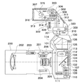
このカメラシステムの構成を示すブロック図である図1で、100はカメラ本体(デジタルカメラのボディ)、200は交換レンズ、300はストロボ装置(閃光装置)である。これら交換レンズ200とストロボ装置300とは、それぞれカメラ本体100に対して着脱可能に装着されている。   In FIG. 1, which is a block diagram showing the configuration of this camera system, 100 is a camera body (digital camera body), 200 is an interchangeable lens, and 300 is a strobe device (flash device). The interchangeable lens 200 and the flash device 300 are detachably attached to the camera body 100, respectively.

まず、カメラ本体100(デジタルカメラのボディ)内の構成について説明する。   First, the configuration in the camera body 100 (the body of the digital camera) will be described.

このカメラ本体100は、マイクロコンピュータであるCCPU(以下、カメラマイコンと言う)101で制御されるよう構成されている。   The camera body 100 is configured to be controlled by a CCPU (hereinafter referred to as camera microcomputer) 101 which is a microcomputer.

このカメラマイコン101は、マイコン内蔵ワンチップIC回路構成となっている。このIC回路構成は、CPU、ROM、RAM、入出力制御回路(I/Oコントロール回路)、マルチプレクサ、タイマ回路、EEPROM(電気的にデータを消去・書き込みできるROM)、A/D、D/Aコンバータ等を含む。このカメラマイコン101は、カメラシステムの制御をソフトウェアで行えるように構成されており、各種の条件判定を行う。   This camera microcomputer 101 has a one-chip IC circuit configuration with a built-in microcomputer. This IC circuit configuration includes a CPU, ROM, RAM, input / output control circuit (I / O control circuit), multiplexer, timer circuit, EEPROM (ROM capable of electrically erasing and writing data), A / D, D / A Includes converters. The camera microcomputer 101 is configured to be able to control the camera system by software, and performs various condition determinations.

このカメラ本体100は、赤外カットフィルタやローパスフィルタ等を含むCCD,CMOS等の撮像素子102を備える。この撮像素子102には、後述するレンズ群202によって撮影時に被写体の像が結像される。また、非撮影時に撮像素子102を遮光し、撮影時に開いて撮像素子102へ光線を導く、シャッター103が設置されている。また、非撮影時にレンズ群202より入射する光の一部を反射しピント板105に結像させる、主ミラー104(ハーフミラー)が設置されている。このピント板105は、不図示の光学ファインダー内のピントを目視で確認できるように構成されている。これらがカメラ本体100の備える撮像系である。   The camera body 100 includes an image sensor 102 such as a CCD or CMOS including an infrared cut filter, a low-pass filter, and the like. An image of a subject is formed on the image sensor 102 at the time of photographing by a lens group 202 described later. Further, a shutter 103 is installed that shields the image sensor 102 when not photographing and opens the light when photographing and guides light to the image sensor 102. In addition, a main mirror 104 (half mirror) that reflects a part of light incident from the lens group 202 and forms an image on the focus plate 105 when not photographing is provided. The focus plate 105 is configured so that the focus in an optical finder (not shown) can be visually confirmed. These are the imaging systems included in the camera body 100.

106は、回路内に実装された測光センサーで被写体の撮影範囲を複数の領域に分割しそれぞれの領域で測光を行うように構成した測光回路である。この測光回路106内の測光センサーは、後述するペンタプリズム114を介してピント板105に結像された被写体像を測光するように構成されている。107は、焦点検出回路であり、回路内の測距センサーが複数点を測距ポイントとして持ち、測光センサーの分割された部分に対応した位置に測距ポイントが含まれているように構成されている。   Reference numeral 106 denotes a photometric circuit configured to divide a photographing range of a subject into a plurality of areas and perform photometry in each area by a photometric sensor mounted in the circuit. The photometric sensor in the photometric circuit 106 is configured to measure the subject image formed on the focus plate 105 via a pentaprism 114 described later. Reference numeral 107 denotes a focus detection circuit, which is configured such that the distance measuring sensor in the circuit has a plurality of points as distance measuring points, and the distance measuring points are included at positions corresponding to the divided portions of the photometric sensor. Yes.

108は、撮像素子102の信号の増幅のゲインを切換えするためのゲイン切換え回路である。このゲイン切換え回路108によるゲインの切換えは、撮影の条件や撮影者の入力等によりカメラマイコン101の指令により行われる。109は、増幅された撮像素子102からのアナログ信号をデジタル信号に変換するA/D変換器である。110は、撮像素子102の増幅された信号入力とA/D変換器109の変換タイミングを同期させるためのタイミングジェネレータ(TG)である。111は、A/D変換器109でディジタル信号に変換された画像データをパラメータにしたがって画像処理を行う、ディジタル信号処理回路である。尚、カメラ本体100には、図示しないが、処理画像の記憶のためのメモリ等が装着されている。   Reference numeral 108 denotes a gain switching circuit for switching the gain of signal amplification of the image sensor 102. The gain switching by the gain switching circuit 108 is performed according to a command from the camera microcomputer 101 according to shooting conditions, a photographer's input, and the like. Reference numeral 109 denotes an A / D converter that converts the amplified analog signal from the image sensor 102 into a digital signal. Reference numeral 110 denotes a timing generator (TG) for synchronizing the amplified signal input of the image sensor 102 and the conversion timing of the A / D converter 109. A digital signal processing circuit 111 performs image processing on image data converted into a digital signal by the A / D converter 109 according to parameters. Although not shown, the camera body 100 is provided with a memory for storing processed images.

このカメラ本体100は、インタフェースの信号ラインSCを介して、交換レンズ200とストロボ装置300との間で、例えばカメラマイコン101をホストとして、データの交換やコマンドの伝達を相互に行うよう構成されている。   The camera body 100 is configured to exchange data and transmit commands between the interchangeable lens 200 and the strobe device 300 via the interface signal line SC, for example, using the camera microcomputer 101 as a host. Yes.

またカメラ本体100は、カメラマイコン101が、インタフェースの信号ラインSCと通信クロック端子を介して、ストロボマイコン310との間で発光開始信号の送信等の通信を行うように構成されている。   The camera body 100 is configured such that the camera microcomputer 101 performs communication such as transmission of a light emission start signal with the flash microcomputer 310 via the interface signal line SC and a communication clock terminal.

さらに、カメラ本体100のカメラマイコン101は、インタフェースの信号ラインSCとデータを送信する端子を介して、レンズマイコン201との間で通信を行うように構成されている。   Furthermore, the camera microcomputer 101 of the camera body 100 is configured to communicate with the lens microcomputer 201 via the interface signal line SC and a terminal for transmitting data.

112は、撮像素子102のゲインの設定の入力操作、カメラの各種設定等を外部から入力可能とするスイッチやボタン等を設けた各種入力部である。113は、各種設定されたモードやその他の撮影情報等を表示する液晶装置や発光素子等からなる表示部である。   Reference numeral 112 denotes various input units provided with switches, buttons, and the like that allow an input operation for gain setting of the image sensor 102 and various camera settings to be input from the outside. A display unit 113 includes a liquid crystal device, a light emitting element, and the like that display various set modes and other shooting information.

114は、ピント板105の被写体像を測光回路106内の測光センサー及び図示しない光学ファインダーに導くペンタプリズムである。115は、レンズ群202より入射し主ミラー104を透過した光線を焦点検出回路107の測距センサーへ導くサブミラーである。   A pentaprism 114 guides the subject image on the focusing screen 105 to a photometric sensor in the photometric circuit 106 and an optical viewfinder (not shown). Reference numeral 115 denotes a sub-mirror that guides the light beam incident from the lens group 202 and transmitted through the main mirror 104 to the distance measuring sensor of the focus detection circuit 107.

次に、本カメラシステムにおける交換レンズ200内の構成と動作について説明する。   Next, the configuration and operation within the interchangeable lens 200 in this camera system will be described.

この交換レンズ200は、交換レンズ200の各部の動作を制御するマイクロコンピュータLPU(以下、レンズマイコン)201を備える。   The interchangeable lens 200 includes a microcomputer LPU (hereinafter referred to as a lens microcomputer) 201 that controls the operation of each part of the interchangeable lens 200.

このレンズマイコン201は、マイコン内蔵ワンチップIC回路構成となっている。IC回路構成は、CPU、ROM、RAM、入出力制御回路(I/Oコントロール回路)、マルチプレクサ、タイマ回路、EEPROM(電気的にデータを消去・書き込みできるROM)、A/D、D/Aコンバータ等を含む。また、このレンズマイコン201は、カメラシステムの制御をソフトウェアで行えるもので、各種の条件判定を行ったり、その記憶装置のROM又はEEPROMにレンズの種別情報(ID)、鏡筒の反射率情報を予め記憶しておく。   This lens microcomputer 201 has a microcomputer built-in one-chip IC circuit configuration. IC circuit configuration includes CPU, ROM, RAM, input / output control circuit (I / O control circuit), multiplexer, timer circuit, EEPROM (ROM capable of electrically erasing / writing data), A / D, D / A converter Etc. The lens microcomputer 201 can control the camera system by software. The lens microcomputer 201 determines various conditions, and stores lens type information (ID) and reflectance information of the lens barrel in the ROM or EEPROM of the storage device. Store in advance.

202は、複数枚で構成されたレンズ群である。203は、レンズ群202の焦点位置合わせ用の光学系を移動させるレンズ駆動部である。この交換レンズ200では、カメラマイコン101が、レンズ群202の駆動量を、カメラ本体100内にある焦点検出回路107の出力に基づいて演算して制御する。   A lens group 202 includes a plurality of lenses. Reference numeral 203 denotes a lens driving unit that moves an optical system for adjusting the focal position of the lens group 202. In the interchangeable lens 200, the camera microcomputer 101 calculates and controls the driving amount of the lens group 202 based on the output of the focus detection circuit 107 in the camera body 100.

204は、レンズ群202の駆動時に位置を検出するエンコーダ204であり、エンコーダ204の出力であるエンコーダ情報により被写体距離情報を検出する。   Reference numeral 204 denotes an encoder 204 that detects a position when the lens group 202 is driven, and detects subject distance information based on encoder information that is an output of the encoder 204.

そして、カメラマイコン101は、算出したレンズ群202の駆動量をレンズマイコン201に通信し、エンコーダ204の駆動情報により駆動量分だけレンズ駆動部203を動作させ、レンズ群202を合焦位置へ移動させる。   The camera microcomputer 101 communicates the calculated driving amount of the lens group 202 to the lens microcomputer 201, operates the lens driving unit 203 by the driving amount according to the driving information of the encoder 204, and moves the lens group 202 to the in-focus position. Let

205は、絞り制御回路206を介してレンズマイコン201により制御される絞りである。   Reference numeral 205 denotes an aperture controlled by the lens microcomputer 201 via the aperture control circuit 206.

なお、この交換レンズ200は、レンズ群202の焦点距離が単焦点のものであっても、ズームレンズのように焦点距離が可変のものであっても良い。   The interchangeable lens 200 may have a single focal length or a variable focal length such as a zoom lens.

上述のように構成された交換レンズ200を備えたカメラシステムでは、カメラマイコン101がレンズマイコン201に通信し、被写体距離情報とレンズの種類(種別)の情報(ID情報)及び鏡筒の反射率情報を取得する。   In the camera system including the interchangeable lens 200 configured as described above, the camera microcomputer 101 communicates with the lens microcomputer 201, and subject distance information, lens type (type) information (ID information), and lens barrel reflectance Get information.

次に、本カメラシステムにおけるストロボ装置300の構成について説明する。   Next, the configuration of the strobe device 300 in this camera system will be described.

このストロボ装置300は、ストロボ装置300各部の動作を制御するマイクロコンピュータFPU(以下、ストロボマイコンという)310を備える。   The strobe device 300 includes a microcomputer FPU (hereinafter referred to as a strobe microcomputer) 310 that controls the operation of each part of the strobe device 300.

このストロボマイコン310は、マイコン内蔵ワンチップIC回路構成となっている。このIC回路構成は、CPU、ROM、RAM、入出力制御回路(I/Oコントロール回路)、マルチプレクサ、タイマ回路、EEPROM(電気的にデータを消去・書き込みできるROM)、A/D、D/Aコンバータ等を含む。このストロボマイコン310は、カメラシステムの制御をソフトウェアで行えるもので、各種の条件判定を行う。   The strobe microcomputer 310 has a one-chip IC circuit configuration with a built-in microcomputer. This IC circuit configuration includes a CPU, ROM, RAM, input / output control circuit (I / O control circuit), multiplexer, timer circuit, EEPROM (ROM capable of electrically erasing and writing data), A / D, D / A Includes converters. The stroboscopic microcomputer 310 can control the camera system by software, and performs various condition determinations.

301は、ストロボの電源(VBAT)としての電池である。302は、図示しないメインコンデンサに発光のためのエネルギーを蓄積させるための電池301の電圧を数百Vに昇圧する昇圧回路である。なお、図示しないメインコンデンサは昇圧回路302に含まれる。メインコンデンサに充電された電圧は、図示しない電圧検出回路により分圧され、分圧された電圧がストロボマイコン310のA/D変換端子に入力される。   Reference numeral 301 denotes a battery as a power source (VBAT) of the strobe. Reference numeral 302 denotes a booster circuit that boosts the voltage of the battery 301 for storing energy for light emission in a main capacitor (not shown) to several hundred volts. A main capacitor (not shown) is included in the booster circuit 302. The voltage charged in the main capacitor is divided by a voltage detection circuit (not shown), and the divided voltage is input to the A / D conversion terminal of the strobe microcomputer 310.

図示しないメインコンデンサに充電されたエネルギーをトリガー回路306から放電管307に印加し、数KVのパルス電圧で励起する事で発光させ、その光を被写体に照射する。   Energy charged in a main capacitor (not shown) is applied from the trigger circuit 306 to the discharge tube 307 and excited by a pulse voltage of several KV to emit light, and the subject is irradiated with the light.

308は、トリガー回路306と共に放電管307の発光の開始を制御し、さらに発光の停止を制御する発光制御回路である。   A light emission control circuit 308 controls the start of light emission of the discharge tube 307 together with the trigger circuit 306 and further controls the stop of light emission.

322は、受光センサーとしてのフォトダイオードであり、直接またはグラスファイバーなどを介して被写体の光を受光する調光素子として構成されている。   Reference numeral 322 denotes a photodiode as a light receiving sensor, which is configured as a light control element that receives light of a subject directly or through a glass fiber or the like.

309は、フォトダイオード322の受光電流を積分する積分回路であり、積分回路309の出力は、コンパレータ312の反転入力端子とストロボマイコン(電圧設定手段)310のA/Dコンバータ端子に入力される。このコンパレータ312の非反転入力端子は、ストロボマイコン310内のD/Aコンバータ出力端子に接続され、コンパレータ312の出力は311のANDゲートの入力端子に接続される。   Reference numeral 309 denotes an integration circuit that integrates the light reception current of the photodiode 322, and the output of the integration circuit 309 is input to the inverting input terminal of the comparator 312 and the A / D converter terminal of the strobe microcomputer (voltage setting means) 310. The non-inverting input terminal of the comparator 312 is connected to the D / A converter output terminal in the flash microcomputer 310, and the output of the comparator 312 is connected to the input terminal of the AND gate 311.

このD/Aコンバータ端子電圧は発光を停止させるための基準電圧であり、ストロボマイコン310により可変できる。本カメラシステムでは、レンズ鏡筒の表面反射率に応じて電圧値を変えるよう構成されている。   This D / A converter terminal voltage is a reference voltage for stopping light emission, and can be varied by the flash microcomputer 310. This camera system is configured to change the voltage value according to the surface reflectance of the lens barrel.

本カメラシステムでは、レンズ鏡筒の反射率が大きく、遠距離の場合に、アンダー露出にあるため、基準レベルより補正量(マイナス)を加えると共に発光停止レベルを下げる。また、本カメラシステムでは、レンズ鏡筒の反射率が小さく、近距離の場合に、基準レベルに設定する。   In this camera system, since the reflectance of the lens barrel is large and the lens barrel is underexposed at a long distance, a correction amount (minus) is added from the reference level and the light emission stop level is lowered. Further, in this camera system, the reference level is set when the reflectance of the lens barrel is small and the distance is short.

前述したANDゲート311のもう一方の入力端子は、ストロボマイコン310の発光制御端子と接続され、ANDゲート311の出力が発光制御回路308に入力される。   The other input terminal of the AND gate 311 described above is connected to the light emission control terminal of the flash microcomputer 310, and the output of the AND gate 311 is input to the light emission control circuit 308.

このストロボ装置300は、反射傘315及びパネル316等から成る閃光の照射角を変更するズーム光学系を備える。反射傘315とズーム光学系316の距離を所定の位置に変更することにより、被写体への照射ガイドナンバー及び配光を変化させる。   The strobe device 300 includes a zoom optical system that changes the irradiation angle of flash light including a reflector 315 and a panel 316. By changing the distance between the reflector 315 and the zoom optical system 316 to a predetermined position, the irradiation guide number and light distribution to the subject are changed.

313は、モーター等から成るズーム光学系316を移動させるズーム駆動部であり、このズーム光学系316の駆動量は、ストロボマイコン310のズーム制御端子より信号を受け制御される。このズーム駆動量は、レンズマイコン201からカメラマイコン101を介してストロボマイコン310に焦点距離情報が送信され、その焦点距離情報に応じてストロボマイコン310がズームの駆動量を演算して決定する。   Reference numeral 313 denotes a zoom drive unit that moves a zoom optical system 316 including a motor or the like. The drive amount of the zoom optical system 316 is controlled by receiving a signal from the zoom control terminal of the flash microcomputer 310. The zoom drive amount is determined by the focal length information being transmitted from the lens microcomputer 201 to the flash microcomputer 310 via the camera microcomputer 101, and the flash microcomputer 310 calculates the zoom drive amount according to the focal length information.

314は、ズーム光学系316のズーム位置を検出するエンコーダ等の位置検出部であり、この位置検出部314は、ストロボマイコン310の位置信号端子に移動情報を与える。この移動情報に基づいて、ストロボマイコン310は、必要な駆動量分だけズーム駆動部313内のモータを動作させてズーム光学系316を移動制御する。   Reference numeral 314 denotes a position detection unit such as an encoder that detects the zoom position of the zoom optical system 316, and the position detection unit 314 gives movement information to the position signal terminal of the flash microcomputer 310. Based on this movement information, the stroboscopic microcomputer 310 controls the movement of the zoom optical system 316 by operating the motor in the zoom drive unit 313 by the required drive amount.

320は、各種入力部(入力インタフェース)であり、例えばストロボ装置300の側面などに配置されたスイッチで構成され、ユーザの操作によりズーム情報の入力が可能に構成されている。   Reference numeral 320 denotes various input units (input interfaces), which are configured with switches disposed on the side surface of the strobe device 300, for example, and configured to allow zoom information to be input by a user operation.

さらに、このストロボ装置300は、ストロボ装置300の各状態を表示する表示部321と、バウンスが可能な発光部350とを備える。   The strobe device 300 further includes a display unit 321 that displays each state of the strobe device 300 and a light emitting unit 350 that can bounce.

次に、本カメラシステムのシーケンスに係わる、カメラマイコン101の具体的な動作について、図2及び図3のフローチャートを参照して説明する。   Next, a specific operation of the camera microcomputer 101 relating to the sequence of the camera system will be described with reference to the flowcharts of FIGS.

このカメラ本体100では、図示しない電源スイッチがオンされるとカメラマイコン101が動作可能となり、カメラマイコン101が、図2に示す撮影用処理におけるステップS1から所定の動作を開始する。   In this camera body 100, when a power switch (not shown) is turned on, the camera microcomputer 101 can operate, and the camera microcomputer 101 starts a predetermined operation from step S1 in the photographing process shown in FIG.

まず、ステップS1では、カメラマイコン101が、自身のメモリやポートの初期化を行う。さらに、カメラマイコン101は、入力部112のスイッチの状態を検知して入力された指令や予め設定された入力情報を読み込み、シャッタースピードの決め方や、絞りの決め方等様々な撮影モードの設定を行う。   First, in step S1, the camera microcomputer 101 initializes its own memory and port. Furthermore, the camera microcomputer 101 detects the state of the switch of the input unit 112 and reads an input command or preset input information, and sets various shooting modes such as how to determine the shutter speed and how to determine the aperture. .

次に、カメラマイコン101は、図示しないシャッターボタンの半押し状態であるSW1がONか否かを判別する(ステップS2)。そして、カメラマイコン101は、OFFのとき(ステップS2でOFF)にこのステップを繰り返し、ONのとき(ステップS2でON)にステップS3に進む。   Next, the camera microcomputer 101 determines whether SW1, which is a half-pressed state of a shutter button (not shown), is ON (step S2). The camera microcomputer 101 repeats this step when it is OFF (OFF at Step S2), and proceeds to Step S3 when it is ON (ON at Step S2).

次に、カメラマイコン101は、交換レンズ200内のレンズマイコン201と通信ラインSCを介して通信を行う(ステップS3)。そして、交換レンズ200の焦点距離情報(以下、レンズの焦点距離情報)や測距、測光に必要な光学情報を取得する。さらに、カメラマイコン101は、同様にしてレンズマイコン201と通信して、レンズの種別情報(ID)、鏡筒の反射率情報を取得する。   Next, the camera microcomputer 101 communicates with the lens microcomputer 201 in the interchangeable lens 200 via the communication line SC (step S3). Then, the focal length information of the interchangeable lens 200 (hereinafter referred to as the focal length information of the lens) and the optical information necessary for distance measurement and photometry are acquired. Further, the camera microcomputer 101 communicates with the lens microcomputer 201 in the same manner to acquire lens type information (ID) and lens barrel reflectance information.

次に、カメラマイコン101は、カメラ本体100にストロボ装置300が装着されているかどうかをチェックする。カメラ本体100にストロボ装置300が装着されている場合(ステップS4でYES)ならばステップS5へ進み、未装着の場合(ステップS4でNO)ならばステップS6へ進む。   Next, the camera microcomputer 101 checks whether or not the strobe device 300 is attached to the camera body 100. If the strobe device 300 is attached to the camera body 100 (YES in step S4), the process proceeds to step S5, and if not (NO in step S4), the process proceeds to step S6.

ストロボ装置300が装着されている場合、カメラマイコン101は、ストロボマイコン310と通信ラインSCとを介して通信し、前述したステップS3にて取得したレンズの焦点距離情報をストロボマイコン310に出力する(ステップS5)。これにより、ストロボマイコン310は、受信した焦点距離情報に基づいてモータ駆動回路313を駆動してエンコーダ314で位置を検出しストロボの照射角を制御する。   When the strobe device 300 is attached, the camera microcomputer 101 communicates with the strobe microcomputer 310 via the communication line SC, and outputs the focal length information of the lens acquired in step S3 described above to the strobe microcomputer 310 ( Step S5). Accordingly, the flash microcomputer 310 drives the motor drive circuit 313 based on the received focal length information, detects the position by the encoder 314, and controls the irradiation angle of the flash.

次に、カメラマイコン101は、ステップS1で設定されたカメラの撮影モードのうち、カメラが自動焦点検出動作を行うモード(AFモード)であるか否かを判定する(ステップS6)。そしてカメラマイコン101は、AFモードであると判定した場合(ステップS6でYES)にステップS7に進み、AFモードでないと判定した場合(ステップS6でNO)にステップS10へ進む。   Next, the camera microcomputer 101 determines whether or not the camera is in a mode (AF mode) in which the camera performs an automatic focus detection operation among the shooting modes of the camera set in step S1 (step S6). If the camera microcomputer 101 determines that the AF mode is selected (YES in step S6), the process proceeds to step S7. If the camera microcomputer 101 determines that the AF mode is not selected (NO in step S6), the process proceeds to step S10.

カメラマイコン101は、ステップS7において、焦点検出回路107を駆動することにより周知の位相差検出法による焦点検出動作を行う。この際、カメラマイコン101は、複数の測距点からどのポイントに合わせるか(測距ポイント)を、前述の入力部112で入力され設定されたポイント又はカメラの撮影モードに応じて決定する。さらに、カメラマイコン101は、近点優先を基本の考え方とした周知の自動選択アルゴリズムなどで測距ポイントを決定しても良い。このステップS7で決定された測距ポイントは、カメラマイコン101内の図示しないRAM(ランダムアクセスメモリー)に記憶される。   In step S7, the camera microcomputer 101 drives the focus detection circuit 107 to perform a focus detection operation by a known phase difference detection method. At this time, the camera microcomputer 101 determines which point (ranging point) to match from a plurality of distance measuring points in accordance with the point input and set by the input unit 112 or the shooting mode of the camera. Further, the camera microcomputer 101 may determine a distance measuring point by a known automatic selection algorithm based on the basic concept of near point priority. The distance measuring point determined in step S7 is stored in a RAM (random access memory) (not shown) in the camera microcomputer 101.

次に、カメラマイコン101は、焦点検出回路107の情報に基づきレンズの駆動量を演算する。そして、カメラマイコン101は、演算した駆動量を、交換レンズ200内のレンズマイコン201へ通信ラインSCを介して送信する。カメラマイコン101の演算結果を受信したレンズマイコン201は、この演算結果に基づいてレンズ駆動回路203を制御し、レンズ群202を合焦位置に駆動する(ステップS8)。   Next, the camera microcomputer 101 calculates a lens driving amount based on information from the focus detection circuit 107. Then, the camera microcomputer 101 transmits the calculated driving amount to the lens microcomputer 201 in the interchangeable lens 200 via the communication line SC. The lens microcomputer 201 that has received the calculation result of the camera microcomputer 101 controls the lens driving circuit 203 based on the calculation result to drive the lens group 202 to the in-focus position (step S8).

次に、カメラマイコン101は、交換レンズ200内のレンズマイコン201と通信ラインSCを介して通信して、被写体距離情報を取得する(ステップS9)。   Next, the camera microcomputer 101 communicates with the lens microcomputer 201 in the interchangeable lens 200 via the communication line SC to acquire subject distance information (step S9).

次に、カメラマイコン101は、例えば、画面を6つのエリアに分割し、被写体輝度値を測光回路106より得る。
その輝度値は、
EVb(i) (i=0〜5)
として、RAMに記憶させる(ステップS10)。
Next, for example, the camera microcomputer 101 divides the screen into six areas and obtains the subject luminance value from the photometric circuit 106.
Its luminance value is
EVb (i) (i = 0 to 5)
Is stored in the RAM (step S10).

次に、カメラマイコン101は、入力部112より入力されたゲイン設定の処理をゲイン切換え回路108により行う(ステップS11)。ここでは、ISO感度設定を行う。   Next, the camera microcomputer 101 performs gain setting processing input from the input unit 112 by the gain switching circuit 108 (step S11). Here, ISO sensitivity is set.

次に、カメラマイコン101は、ストロボマイコン310と通信ラインSCを介して通信し、ゲイン切換え回路108にて取得したゲイン設定情報をストロボマイコン310に出力する。   Next, the camera microcomputer 101 communicates with the flash microcomputer 310 via the communication line SC, and outputs gain setting information acquired by the gain switching circuit 108 to the flash microcomputer 310.

次に、カメラマイコン101は、複数のエリアの被写体輝度値EVbから、周知のアルゴリズムを利用して露出値(EVs)を決定する(ステップS12)。   Next, the camera microcomputer 101 determines an exposure value (EVs) from the subject luminance values EVb of a plurality of areas using a known algorithm (step S12).

次に、カメラマイコン101は、ストロボマイコン310が充電完了信号を出力しているかどうかをチェックする(ステップS13)。ここで、カメラマイコン101は、ストロボマイコン310が充電完了信号を出力していると判定した場合(ステップS13でYES)に、ステップS14へ進み、出力していないと判定した場合(ステップS13でNO)にステップS15へ進む。なお、カメラマイコン101は、このステップS13におけるストロボマイコン310が充電完了信号を出力しているかどうかの判定結果を、後のステップで用いるために記憶しておく。   Next, the camera microcomputer 101 checks whether or not the flash microcomputer 310 has output a charging completion signal (step S13). Here, when the camera microcomputer 101 determines that the flash microcomputer 310 is outputting the charge completion signal (YES in step S13), the camera microcomputer 101 proceeds to step S14, and determines that it is not output (NO in step S13). ) Go to Step S15. The camera microcomputer 101 stores the determination result of whether or not the strobe microcomputer 310 outputs a charge completion signal in step S13 for use in a later step.

次に、カメラマイコン101は、ストロボ撮影を行うために適したシャッタ速度(Tv)と絞り値(Av)とを上記ステップS10にて得られた測光出力に基づいて決定する(ステップS14)。   Next, the camera microcomputer 101 determines a shutter speed (Tv) and an aperture value (Av) suitable for performing flash photography based on the photometric output obtained in step S10 (step S14).

次に、カメラマイコン101は、自然光撮影(ストロボ装置300を発光させない撮影)を行うために適したシャッタ速度(Tv)と絞り値(Av)とを上記ステップS10にて得られた測光出力に基づいて決定する。上記ステップS14又はステップS15の処理が実行されると、いずれの場合もステップS16へ進む。   Next, the camera microcomputer 101 determines a shutter speed (Tv) and an aperture value (Av) suitable for performing natural light photography (photographing without causing the flash device 300 to emit light) based on the photometric output obtained in step S10. To decide. When the process of step S14 or step S15 is executed, the process proceeds to step S16 in any case.

次に、カメラマイコン101は、ストロボマイコン310と通信ラインSCを介して通信し、その他のストロボに関する情報をストロボマイコン310に出力する(ステップS16)。   Next, the camera microcomputer 101 communicates with the strobe microcomputer 310 via the communication line SC, and outputs information about other strobes to the strobe microcomputer 310 (step S16).

次に、カメラマイコン101は、図示しない撮影開始のスイッチであるSW2がONであるか否かを判定し、OFFであると判定した場合にステップS1からステップS16までの動作を繰り返す。また、カメラマイコン101は、ONであると判定した場合にステップS17に続く、図3のフローチャートで示した一連のレリーズ動作の処理を開始する。   Next, the camera microcomputer 101 determines whether SW2, which is a shooting start switch (not shown), is ON. If it is determined to be OFF, the operation from step S1 to step S16 is repeated. If the camera microcomputer 101 determines that the camera is ON, the camera microcomputer 101 starts a series of release operation processes shown in the flowchart of FIG.

次に、レリーズ動作の処理について、図3のフローチャートを参照して説明する。   Next, the release operation process will be described with reference to the flowchart of FIG.

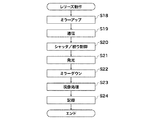
このレリーズ動作の処理が開始すると、カメラマイコン101は、露光動作に先立って主ミラー104をアップさせ、撮影光路内から退去させる(ステップS18)。   When the processing of the release operation is started, the camera microcomputer 101 raises the main mirror 104 prior to the exposure operation and moves it away from the photographing optical path (step S18).

次に、カメラマイコン101は、SCラインを介してストロボマイコン310へストロボ情報をストロボ装置300に送信する(ステップS19)。   Next, the camera microcomputer 101 transmits strobe information to the strobe device 300 to the strobe microcomputer 310 via the SC line (step S19).

次に、カメラマイコン101は、決定された露光値(EVs)に基づく絞り値(AV)になるようにレンズマイコン201に指令を出す。これと共に、カメラマイコン101は、決定されたシャッタースピード値(TV)になるように図示しないシャッター制御回路を介してシャッター103を制御する(ステップS20)。   Next, the camera microcomputer 101 issues a command to the lens microcomputer 201 to obtain an aperture value (AV) based on the determined exposure value (EVs). At the same time, the camera microcomputer 101 controls the shutter 103 via a shutter control circuit (not shown) so that the determined shutter speed value (TV) is obtained (step S20).

次に、カメラマイコン101は、シャッター103の全開に同期し、SCラインを介してストロボマイコン310に発光信号を与える。これと共に、ストロボマイコン310は、適正な発光量になるようにメイン発光制御を行う(ステップS21)。なお、ストロボ発光の詳細な説明は後述する。   Next, the camera microcomputer 101 gives a light emission signal to the flash microcomputer 310 via the SC line in synchronization with the fully opening of the shutter 103. At the same time, the flash microcomputer 310 performs main light emission control so as to obtain an appropriate light emission amount (step S21). A detailed description of the strobe light emission will be given later.

次に、カメラマイコン101は、上述した一連の露光動作を終了させると、撮影光路より退去させていた主ミラー104をダウンさせて再び撮影光路内に斜状にセットする(ステップS22)。   Next, when the above-described series of exposure operations is completed, the camera microcomputer 101 lowers the main mirror 104 that has been retracted from the photographing optical path and sets it again in the oblique manner in the photographing optical path (step S22).

次に、カメラマイコン101は、撮像素子102の画素データをゲイン切換え回路108で設定されたゲインで増幅した信号を生成し、この増幅した信号をA/D変換器109でデジタル信号として変換する。このようにして変換された画素データは、信号処理回路111で、ホワイトバランス等の所定の信号処理が施される(ステップS23)。   Next, the camera microcomputer 101 generates a signal obtained by amplifying the pixel data of the image sensor 102 with the gain set by the gain switching circuit 108, and converts the amplified signal as a digital signal by the A / D converter 109. The pixel data thus converted is subjected to predetermined signal processing such as white balance in the signal processing circuit 111 (step S23).

次に、カメラマイコン101は、上述のように処理された画像データを、図示しないメモリに記憶して(ステップS24)撮影のルーチンを終了する。   Next, the camera microcomputer 101 stores the image data processed as described above in a memory (not shown) (step S24) and ends the shooting routine.

次に、ストロボ装置300内のストロボマイコン310での具体的な動作(ストロボ制御処理)について、図4のフローチャートを参照して説明する。   Next, a specific operation (strobe control processing) in the strobe microcomputer 310 in the strobe device 300 will be described with reference to the flowchart of FIG.

このストロボ装置300は、図示しない電源スイッチがオンされるとストロボマイコン310が動作可能となり、ストロボマイコン310が、図4のステップS101から所定の動作を開始する。   In the strobe device 300, when a power switch (not shown) is turned on, the strobe microcomputer 310 can operate, and the strobe microcomputer 310 starts a predetermined operation from step S101 in FIG.

まず、ステップS101では、ストロボマイコン310が、自身のメモリやポートの初期化を行う。さらに、ストロボマイコン310は、入力されたスイッチの状態を検知して入力された指令や予め設定された入力情報を読み込み、ストロボ撮影モードや発光量等の設定を行う。   First, in step S101, the flash microcomputer 310 initializes its own memory and port. Further, the flash microcomputer 310 detects the state of the input switch, reads the input command and preset input information, and sets the flash shooting mode, the light emission amount, and the like.

次に、ストロボマイコン310は、カメラマイコン101より通信ラインSCを介してストロボ情報を受信する。するとストロボマイコン310は、ストロボ情報をストロボマイコン310内の図示しないRAM(ランダムアクセスメモリー)に記憶させる。   Next, the flash microcomputer 310 receives flash information from the camera microcomputer 101 via the communication line SC. Then, the flash microcomputer 310 stores the flash information in a RAM (random access memory) (not shown) in the flash microcomputer 310.

次に、ストロボマイコン310は、昇圧回路302の動作を開始させて発光の準備を行う(ステップS102)。   Next, the flash microcomputer 310 starts the operation of the booster circuit 302 and prepares for light emission (step S102).

次に、ストロボマイコン310は、カメラマイコン101から通信ラインSCを介して受信したレンズの焦点距離情報をチェックする。そして、ストロボマイコン310は、カメラマイコン101から受信したレンズの焦点距離情報を自身のメモリ内に記憶(格納)する。また、これ以前にレンズの焦点距離情報を自身のメモリ内に記憶していたならば、記憶内容を更新する(ステップS103)。   Next, the flash microcomputer 310 checks the focal length information of the lens received from the camera microcomputer 101 via the communication line SC. Then, the flash microcomputer 310 stores (stores) the focal length information of the lens received from the camera microcomputer 101 in its own memory. If the focal length information of the lens has been stored in its own memory before this, the stored content is updated (step S103).

次に、ストロボマイコン310は、自身のメモリ内に記憶されたレンズの焦点距離情報を表示部321に表示する(ステップS104)。   Next, the flash microcomputer 310 displays the focal length information of the lens stored in its own memory on the display unit 321 (step S104).

次に、ストロボマイコン310は、ストロボ光の照射角が上記ステップS104にて選定された照射角のポジションになるようにエンコーダ314を介してストロボマイコン310の位置信号端子に移動情報を与える。そして、ストロボマイコン310は、位置信号端子によって必要な駆動量分だけズーム駆動部313内のモータを動作させ、エンコ−ダ314の位置信号により所定の位置へ動作させる(ステップS105)。   Next, the stroboscopic microcomputer 310 gives movement information to the position signal terminal of the stroboscopic microcomputer 310 via the encoder 314 so that the illuminating angle of the stroboscopic light becomes the position of the irradiating angle selected in step S104. The stroboscopic microcomputer 310 operates the motor in the zoom driving unit 313 by a necessary driving amount by the position signal terminal, and operates to a predetermined position by the position signal of the encoder 314 (step S105).

次に、ストロボマイコン310は、カメラマイコン101から送信されたレンズの種別情報(ID)、鏡筒の反射率情報、距離情報を取得する(ステップS106)。   Next, the flash microcomputer 310 acquires lens type information (ID), lens barrel reflectance information, and distance information transmitted from the camera microcomputer 101 (step S106).

次に、ストロボマイコン310は、レンズの種別情報(ID)、鏡筒の反射率情報により外部調光の補正レベルを合焦した距離情報に応じて補正する。すなわち、ストロボマイコン310は、取得したレンズの種別情報(ID)、鏡筒の反射率情報、距離情報から、ステップS107〜ステップS110の処理によって、補正方法を設定する。   Next, the stroboscopic microcomputer 310 corrects the correction level of the external dimming according to the focused distance information based on the lens type information (ID) and the reflectance information of the lens barrel. That is, the stroboscopic microcomputer 310 sets a correction method by the processing of step S107 to step S110 from the acquired lens type information (ID), lens barrel reflectance information, and distance information.

以下、この補正の方法の設定について、図4、図7及び図10を参照して説明する。なお、図10に例示する補正量では、レンズの判別を4つにしているが、これに限られるものではなく、5以上の場合に分けて判別するようにしてもよい。   Hereinafter, setting of the correction method will be described with reference to FIGS. 4, 7, and 10. In the correction amount illustrated in FIG. 10, the determination of the lens is four. However, the correction is not limited to this, and the determination may be made in five or more cases.

このストロボ装置300では、外部調光の補正レベルを合焦した距離情報に応じて補正する機能が、以下のように構成されている。   In the strobe device 300, the function of correcting the correction level of the external dimming according to the focused distance information is configured as follows.

このストロボ装置300では、被写体から反射した光を調光素子322で受光して積分回路309で積分した出力信号が、コンパレータ312の反転入力端子とストロボマイコン310のA/Dコンバータ端子に入力される構成となっている。   In the strobe device 300, an output signal obtained by receiving the light reflected from the subject by the dimming element 322 and integrating the light by the integrating circuit 309 is input to the inverting input terminal of the comparator 312 and the A / D converter terminal of the strobe microcomputer 310. It has a configuration.

このコンパレータ312の非反転入力端子は、ストロボマイコン310内のD/Aコンバータ出力端子に接続されている。このコンパレータ312の出力端子は、ANDゲート311の入力端子に接続されている。   A non-inverting input terminal of the comparator 312 is connected to a D / A converter output terminal in the flash microcomputer 310. The output terminal of the comparator 312 is connected to the input terminal of the AND gate 311.

このANDゲート311から出力された信号は、発光制御回路308に入力される。発光制御回路308は、ANDゲート311からの信号を受信すると、発光を停止させる。   The signal output from the AND gate 311 is input to the light emission control circuit 308. When receiving the signal from the AND gate 311, the light emission control circuit 308 stops the light emission.

ここで、ストロボマイコン310内のD/Aコンバータ端子電圧は、発光を停止させるための基準電圧(VTH)となっている。この基準電圧(VTH)は、ストロボマイコン310により可変可能に構成されており、下記式で求められる。   Here, the D / A converter terminal voltage in the flash microcomputer 310 is a reference voltage (VTH) for stopping light emission. This reference voltage (VTH) is configured to be variable by the stroboscopic microcomputer 310 and is obtained by the following equation.

基準電圧(VTH)=VTH0+k+L
ここで、
VTH0:鏡筒の反射率の影響が無い時の基準電圧
k:レンズの鏡筒の反射率による補正量
L:被写体距離による補正量
k+L:補正量
である。
Reference voltage (VTH) = VTH0 + k + L
here,
VTH0: reference voltage when there is no influence of the reflectance of the lens barrel k: a correction amount L based on the reflectance of the lens barrel L: a correction amount k + L based on the subject distance.

この外部調光の補正の具体的な内容としては、レンズ鏡筒の反射率が大きく、遠距離の場合に、アンダー露出にあるため基準レベルより補正量(マイナス)を加え、発光停止レベルを下げる(発光量を大きくする)。また、この外部調光の補正では、レンズ鏡筒の反射率が小さく、近距離の場合には基準レベルとする。   Specifically, the external dimming correction is performed by adding a correction amount (minus) from the reference level to reduce the light emission stop level because the lens barrel has a large reflectance and is underexposed at a long distance because it is underexposed. (Increase light emission). In this external dimming correction, the reflectance of the lens barrel is small, and the reference level is used in the case of a short distance.

上述の外部調光の補正を行うため、図4のフローチャートにおけるステップS107では、ストロボマイコン310が、レンズの種別情報(ID)が「001」であると判断した場合(ステップS107でYES)に、ステップS111へ進む。   In order to perform the above-described external dimming correction, in step S107 in the flowchart of FIG. 4, when the flash microcomputer 310 determines that the lens type information (ID) is “001” (YES in step S107), Proceed to step S111.

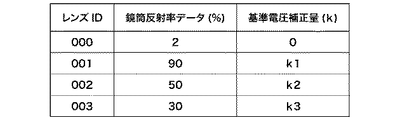
次に、ストロボマイコン310は、レンズの距離情報を使用して被写体距離による補正量Lを決める(ステップS111)。そして、ストロボマイコン310は、図10に示すテーブルを参照して、レンズの種別情報(ID)が「001」の鏡筒反射率情報に対応した基準電圧補正量「k1」を求める。そして、ストロボマイコン310は、基準電圧補正量「k1」に基づいて、基準電圧VTH1を設定(ステップS112)し、次のステップS117へ進む。   Next, the flash microcomputer 310 determines the correction amount L based on the subject distance using the lens distance information (step S111). Then, the flash microcomputer 310 refers to the table shown in FIG. 10 to obtain the reference voltage correction amount “k1” corresponding to the lens barrel reflectance information whose lens type information (ID) is “001”. The stroboscopic microcomputer 310 sets the reference voltage VTH1 based on the reference voltage correction amount “k1” (step S112), and proceeds to the next step S117.

また、ストロボマイコン310は、レンズの種別情報(ID)が「001」でないと判断した場合(ステップS107でNO)にステップS108へ進む。   If the flash microcomputer 310 determines that the lens type information (ID) is not “001” (NO in step S107), the flash microcomputer 310 proceeds to step S108.

次に、ストロボマイコン310は、レンズの種別情報(ID)が「002」と判定した場合(ステップS108でYES)に、ステップS113へ進む。   Next, when the flash microcomputer 310 determines that the lens type information (ID) is “002” (YES in step S108), the flash microcomputer 310 proceeds to step S113.

次に、ストロボマイコン310は、レンズの距離情報を使用して被写体距離による補正量Lを決める(ステップS113)。そして、ストロボマイコン310は、図10に示すテーブルを参照して、レンズの種別情報(ID)が「002」の鏡筒反射率情報に対応した基準電圧補正量「k2」を求める。そして、ストロボマイコン310は、基準電圧補正量「k2」に基づいて、基準電圧VTH2を設定(ステップS114)し、次のステップS117へ進む。   Next, the flash microcomputer 310 determines the correction amount L based on the subject distance using the lens distance information (step S113). Then, the flash microcomputer 310 obtains the reference voltage correction amount “k2” corresponding to the lens barrel reflectance information whose lens type information (ID) is “002” with reference to the table shown in FIG. Then, the flash microcomputer 310 sets the reference voltage VTH2 based on the reference voltage correction amount “k2” (step S114), and proceeds to the next step S117.

また、ストロボマイコン310は、レンズの種別情報(ID)が「002」でないと判断した場合(ステップS108でNO)にステップS109へ進む。   If the flash microcomputer 310 determines that the lens type information (ID) is not “002” (NO in step S108), the flash microcomputer 310 proceeds to step S109.

次に、ストロボマイコン310は、レンズの種別情報(ID)が「003」と判定した場合(ステップS109でYES)に、ステップS115へ進む。   Next, when it is determined that the lens type information (ID) is “003” (YES in step S109), the flash microcomputer 310 proceeds to step S115.

次に、ストロボマイコン310は、レンズの距離情報を使用して被写体距離による補正量Lを決める(ステップS115)。そして、ストロボマイコン310は、図10に示すテーブルを参照して、レンズの種別情報(ID)が「003」の鏡筒反射率情報に対応した基準電圧補正量「k3」を求める。そして、ストロボマイコン310は、基準電圧補正量「k3」に基づいて、基準電圧VTH3を設定(ステップS112)し、次のステップS117へ進む。   Next, the flash microcomputer 310 uses the lens distance information to determine a correction amount L based on the subject distance (step S115). Then, the flash microcomputer 310 refers to the table shown in FIG. 10 to obtain the reference voltage correction amount “k3” corresponding to the lens barrel reflectance information whose lens type information (ID) is “003”. Then, the flash microcomputer 310 sets the reference voltage VTH3 based on the reference voltage correction amount “k3” (step S112), and proceeds to the next step S117.

また、ストロボマイコン310は、レンズの種別情報(ID)が「003」でないと判断した場合(ステップS109でNO)にステップS110へ進む。この場合、ストロボマイコン310が鏡筒反射率がほとんどないと判断した場合であるので、ストロボマイコン310は、基準電圧VTH0を設定(ステップS110)し、次のステップS117へ進む。   If the flash microcomputer 310 determines that the lens type information (ID) is not “003” (NO in step S109), the flash microcomputer 310 proceeds to step S110. In this case, since the stroboscopic microcomputer 310 determines that there is almost no lens barrel reflectance, the stroboscopic microcomputer 310 sets the reference voltage VTH0 (step S110), and proceeds to the next step S117.

なお、上述した基準電圧は、下記式の関係がある。
[式1]
VTH0>VTH1>VTH2>VTH3
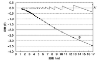
また、上述したように補正することにより、図7に示すように、補正前はBのカーブのように発光量がアンダーになったのに対し、基準データを被写体距離に対応して補正することで、A´のカーブのように適正な範囲に補正できる。なお、ここでは、テーブルを参照して補正したが、演算により算出しても同様の結果を得ることができる。
In addition, the reference voltage mentioned above has the relationship of the following formula.
[Formula 1]
VTH0>VTH1>VTH2> VTH3
Further, by correcting as described above, as shown in FIG. 7, before the correction, the light emission amount is under as shown by the curve B, but the reference data is corrected corresponding to the subject distance. Thus, it can be corrected to an appropriate range like the curve of A ′. Here, the correction is made with reference to the table, but the same result can be obtained even if calculation is performed.

次に、ストロボマイコン310は、昇圧回路302が昇圧した電圧が放電管307の発光に必要な電圧レベルにまで達したか(充電完了か)どうかを判定する(ステップS117)。   Next, the stroboscopic microcomputer 310 determines whether or not the voltage boosted by the booster circuit 302 has reached a voltage level necessary for light emission of the discharge tube 307 (whether charging is complete) (step S117).

そして、ストロボマイコン310は、昇圧回路302が昇圧した電圧が放電管307の発光に必要な電圧レベルにまで達していないと判定した場合に、ステップS123へ進む。   If the stroboscopic microcomputer 310 determines that the voltage boosted by the booster circuit 302 has not reached the voltage level necessary for the light emission of the discharge tube 307, the process proceeds to step S123.

次に、ストロボマイコン310は、充電未完信号を出力してストロボの発光準備ができていないことを通信ラインSCによってカメラマイコン101に送信すると共に、充電信号を昇圧回路302に送信する(ステップS123)。その後、ストロボマイコン310は、ステップS102へ戻り、上述したステップを繰り返す。   Next, the flash microcomputer 310 outputs a charge incomplete signal to transmit that the flash is not ready to emit light to the camera microcomputer 101 via the communication line SC, and transmits a charge signal to the booster circuit 302 (step S123). . Thereafter, the flash microcomputer 310 returns to step S102 and repeats the above-described steps.

また、ストロボマイコン310は、放電管307の発光に必要な電圧レベルにまで達していると判定した場合に、ステップS118に進む。   If the flash microcomputer 310 determines that the voltage level necessary for the light emission of the discharge tube 307 has been reached, the process proceeds to step S118.

次に、ストロボマイコン310は、充電完了信号を出力してストロボの発光準備ができたことを通信ラインSCによってカメラマイコン101に送信する。   Next, the flash microcomputer 310 outputs a charge completion signal and transmits that the flash is ready to emit light to the camera microcomputer 101 via the communication line SC.

次に、ストロボマイコン310は、カメラマイコン101より発光開始用信号が出力されているかどうかを判定し、発光開始用信号が出力されていないと判定した場合(ステップS119でNO)にステップS102に戻り、前述したステップを繰り返す。   Next, the flash microcomputer 310 determines whether or not the light emission start signal is output from the camera microcomputer 101. If it is determined that the light emission start signal is not output (NO in step S119), the process returns to step S102. Repeat the above steps.

一方、ストロボマイコン310は、発光開始用信号が出力されていると判定した場合(ステップS119でYES)に、ステップS120へ進む。そして、ストロボマイコン310は、トリガ回路306とストロボマイコン310の発光制御端子よりANDゲート311を介して発光制御回路308にトリガ信号を与えてストロボの発光を開始させる(ステップS120)。   On the other hand, when it is determined that the light emission start signal is output (YES in step S119), the flash microcomputer 310 proceeds to step S120. Then, the strobe microcomputer 310 gives a trigger signal to the light emission control circuit 308 via the AND gate 311 from the light emission control terminal of the trigger circuit 306 and the strobe microcomputer 310 to start the light emission of the strobe (step S120).

次に、ストロボマイコン310は、被写体からの反射光をフォトダイオード322で受光すると、積分回路309でフォトダイオード322の受光電流を積分させる。そして、この積分回路309で積分された出力は、コンパレータ312の反転入力端子とストロボマイコン310のA/Dコンバータ端子に入力される。このとき、コンパレータ312の非反転入力は、ストロボマイコン310内のD/Aコンバータ出力端子に接続され、前述の如くして、適正光量に相当する発光量に相当するD/Aコンバータ値である基準電圧VTHが設定されている状態にある。   Next, when the flash microcomputer 310 receives the reflected light from the subject with the photodiode 322, the integration circuit 309 integrates the light reception current of the photodiode 322. The output integrated by the integration circuit 309 is input to the inverting input terminal of the comparator 312 and the A / D converter terminal of the strobe microcomputer 310. At this time, the non-inverting input of the comparator 312 is connected to the D / A converter output terminal in the flash microcomputer 310, and as described above, the reference is a D / A converter value corresponding to the light emission amount corresponding to the appropriate light amount. The voltage VTH is set.

次に、ストロボマイコン310は、設定されている基準電圧VTHのレベルまで達するまで発光を継続し(ステップS121でNO)、基準電圧VTHのレベルに達達した場合(ステップS121でYES)にステップS122へ進む。   Next, the flash microcomputer 310 continues to emit light until it reaches the set reference voltage VTH level (NO in step S121), and when it reaches the reference voltage VTH level (YES in step S121), it proceeds to step S122. Proceed to

次に、ストロボマイコン310は、ANDゲート311より発光停止信号を出し発光制御回路308により発光を停止し、ステップS102へ戻り、前述したステップを繰り返す。   Next, the flash microcomputer 310 outputs a light emission stop signal from the AND gate 311 and stops the light emission by the light emission control circuit 308, returns to step S102, and repeats the above steps.

次に、本実施の形態に係わるカメラシステムによる効果を理解するための比較例について、図5及び図6を参照して説明する。   Next, a comparative example for understanding the effects of the camera system according to the present embodiment will be described with reference to FIGS.

図5は本実施形態のカメラシステムで被写体を撮影するときの概略説明図で、500は撮影する被写体、100はカメラ本体、200は交換レンズ、300はストロボ装置(閃光装置)、350は発光部、322は調光素子であるフォトダイオードである。   FIG. 5 is a schematic explanatory diagram when a subject is photographed by the camera system of the present embodiment, 500 is a subject to be photographed, 100 is a camera body, 200 is an interchangeable lens, 300 is a strobe device (flash device), and 350 is a light emitting unit. Reference numeral 322 denotes a photodiode which is a light control element.

このようなカメラシステムに用いられる交換レンズ200は、レンズの焦点距離の違いや用途によってレンズ鏡筒に表面の色が異なり反射率が異なるものが存在する。   As for the interchangeable lens 200 used in such a camera system, there is a lens barrel whose surface color is different and reflectance is different depending on a difference in focal length of the lens or a use.

図5(a)に被写体が近距離の場合を示すように、発光部350にて発光した光(L1)は、被写体500に反射して(L2)調光素子322に受光される。このとき発光部350からの光の一部は、直接光(L3)として交換レンズ200で反射され、この反射した光(L4)は、その一部が調光素子に受光される。   As shown in FIG. 5A, the light (L 1) emitted from the light emitting unit 350 is reflected by the subject 500 (L 2) and received by the dimmer 322. At this time, a part of the light from the light emitting unit 350 is reflected by the interchangeable lens 200 as direct light (L3), and a part of the reflected light (L4) is received by the light control element.

ここで、レンズ鏡筒の反射率が小さく、近距離の場合には、「被写体からの反射光(L2)>レンズ鏡筒反射光(L4)」であるため、調光は適正に行なわれる。   Here, when the reflectance of the lens barrel is small and the distance is short, “reflected light from the subject (L2)> reflected light of the lens barrel (L4)”, and thus dimming is performed appropriately.

しかし、図5(b)に示すように被写体が遠距離の場合には、発光部350で発光した光(L1’)が被写体500で反射して(L2’)調光素子322に受光される。このとき発光部350からの光の一部は、直接光(L3’)として交換レンズ200で反射され、反射した光(L4’)が調光素子に受光される。   However, as shown in FIG. 5B, when the subject is at a long distance, the light (L1 ′) emitted from the light emitting unit 350 is reflected by the subject 500 (L2 ′) and received by the light control element 322. . At this time, part of the light from the light emitting unit 350 is reflected by the interchangeable lens 200 as direct light (L3 ′), and the reflected light (L4 ′) is received by the light control element.

このような、レンズ鏡筒の反射率が大きく、遠距離の場合には、「被写体からの反射光(L2’)<レンズ鏡筒反射光(L4’)」の関係にあるため、調光がアンダーになってしまう。   In such a case where the reflectance of the lens barrel is large and the distance is long, the relationship of “reflected light from the subject (L2 ′) <lens barrel reflected light (L4 ′)” is satisfied. It will be under.

このときの状態を図6のグラフを参照して説明する。この図6のグラフでは、横軸に被写体距離をとり、縦軸に適正光量に対する段差が示してある。また、図6のAは、レンズ鏡筒の反射率が低い場合の精度を示す。図6のBは、レンズ鏡筒の反射率が高い(例えば、レンズ鏡筒の色が白)場合の発光量の精度を示す。Aの場合には、被写体距離によらず発光量の精度がほぼ一定であるが、Bの場合には、被写体距離に応じて依存して発光量の精度が下降する。   The state at this time will be described with reference to the graph of FIG. In the graph of FIG. 6, the horizontal axis indicates the subject distance, and the vertical axis indicates the step with respect to the appropriate light amount. 6A shows the accuracy when the reflectance of the lens barrel is low. FIG. 6B shows the accuracy of the light emission amount when the reflectance of the lens barrel is high (for example, the color of the lens barrel is white). In the case of A, the accuracy of the light emission amount is almost constant regardless of the subject distance, but in the case of B, the accuracy of the light emission amount decreases depending on the subject distance.

また、図6のグラフの(a)の位置が、図5(a)の場合に相当し、図6のグラフの(b)の位置が、図5(b)の場合に相当している。   Moreover, the position of (a) of the graph of FIG. 6 corresponds to the case of FIG. 5 (a), and the position of (b) of the graph of FIG. 6 corresponds to the case of FIG.

図6から、レンズ鏡筒の反射率が高い場合には、被写体からの反射光とレンズ鏡筒からの反射光のバランスが被写体距離に応じて大きく変化し、被写体距離が遠いほど発光量の精度に影響することがわかる。   From FIG. 6, when the reflectance of the lens barrel is high, the balance between the reflected light from the subject and the reflected light from the lens barrel changes greatly according to the subject distance, and the accuracy of the light emission amount increases as the subject distance increases. It can be seen that it affects.

よって、本実施の形態に係わるカメラシステムでは、外部調光の補正を、レンズ鏡筒の反射率が大きく、遠距離の場合に、基準レベルより補正量(マイナス)を加え、発光停止レベルを下げてアンダー露出を補正する。また、この外部調光の補正では、レンズ鏡筒の反射率が小さく、近距離の場合に、基準レベルとする。これにより本実施の形態に係わるカメラシステムでは、交換レンズの種類によらず適正な外部調光の補正を行うことができる。さらに、このカメラシステムでは、調光の遠距離での精度向上と、調光センサの配置位置の自由度の増加を両立でき、しかも、調光センサをレンズ近傍に配置できるので、ストロボ装置を小型化できる。   Therefore, in the camera system according to the present embodiment, correction of external dimming is performed by adding a correction amount (minus) from the reference level and reducing the light emission stop level when the reflectance of the lens barrel is large and the distance is long. To correct underexposure. In this external dimming correction, the reference level is set when the reflectance of the lens barrel is small and the distance is short. Thereby, in the camera system according to the present embodiment, it is possible to correct external dimming appropriately regardless of the type of interchangeable lens. Furthermore, with this camera system, it is possible to achieve both improvement in the accuracy of light control over long distances and an increase in the degree of freedom of the position of the light control sensor. Can be

〔第2実施の形態〕
以下、本発明の第2実施の形態について、図8及び図9を参照して説明する。本第2実施の形態に係わるカメラシステムでは、カメラ本体100とストロボ装置300とが、延長コードで接続された構成となっている。
[Second Embodiment]
Hereinafter, a second embodiment of the present invention will be described with reference to FIGS. In the camera system according to the second embodiment, the camera body 100 and the strobe device 300 are connected by an extension cord.

図8のブロック図で、400は、カメラとストロボ装置を接続する延長コードであり、それぞれの通信端子は公知の脱着が可能なコネクタで構成されている。また、401、402は、インターフェース回路で、公知のバッファ回路や接続認識回路で構成されている。   In the block diagram of FIG. 8, reference numeral 400 denotes an extension cord for connecting the camera and the strobe device, and each communication terminal is constituted by a known detachable connector. Reference numerals 401 and 402 denote interface circuits, which are configured by known buffer circuits and connection recognition circuits.

なお、図8のブロック図における以上説明した以外のものは、前述した図1のブロック図で説明したものと同様であるので、同一部材には同一符号を付すこととして、その説明を省略する。   In the block diagram of FIG. 8, the components other than those described above are the same as those described in the block diagram of FIG. 1 described above, and therefore the same members are denoted by the same reference numerals and the description thereof is omitted.

次に、本第2実施の形態に係わるカメラシステムにおける、ストロボ制御処理について、図9のフローチャートを参照して説明する。なお、この図9の動作のフローチャートは、前述した図4のフローチャートと対応するので、異なる部分についてのみ説明することとし、同様に動作するステップには、同一符号を付すこととして、その説明を省略する。   Next, strobe control processing in the camera system according to the second embodiment will be described with reference to the flowchart of FIG. The flowchart of the operation in FIG. 9 corresponds to the flowchart of FIG. 4 described above, and therefore only different parts will be described. To do.

このストロボ制御処理では、カメラシステムの電源スイッチが入力されると、ストロボマイコン310が、前述したようにステップS101からステップS105までの動作を実行する。そして、ストロボマイコン310は、ストロボ光の照射角が選定された照射角のポジションになるように動作(ステップS105)させた後、ステップS105−2へ進む。   In this strobe control process, when the power switch of the camera system is input, the strobe microcomputer 310 performs the operations from step S101 to step S105 as described above. The stroboscopic microcomputer 310 operates (step S105) so that the irradiation angle of the stroboscopic light becomes the position of the selected irradiation angle, and then proceeds to step S105-2.

このステップS105−2で、ストロボマイコン310は、延長コードが接続されているか否かをインターフェース回路401,402により判断する。ここで、ストロボマイコン310は、延長コードが接続された状態のオフカメラであると判定した場合(ステップS105−2でYES)に、ステップS110へ進み、オフカメラでないと判定した場合(ステップS105−2でNO)にステップS106へ進む。   In step S105-2, the flash microcomputer 310 determines whether the extension cord is connected by using the interface circuits 401 and 402. If the flash microcomputer 310 determines that the camera is an off-camera with the extension cord connected (YES in step S105-2), the flash microcomputer 310 proceeds to step S110 and determines that the camera is not an off-camera (step S105-). 2), the process proceeds to step S106.

次に、ストロボマイコン310は、オフカメラでない場合の処理として、前述した図4のステップS106からステップS116と同じ動作を行なう。   Next, the flash microcomputer 310 performs the same operation as the above-described step S106 to step S116 in FIG.

このように、本第2実施の形態に係わるカメラシステムでは、カメラ本体100とストロボ装置300が脱着可能なコードで接続されたことを検出する手段を備える。そして、ストロボマイコン310は、コードが接続されているときに、レンズ情報と距離情報によって調光素子の発光停止時期の補正を行なわないよう制御する。これにより、ストロボ装置300がカメラ本体100から離れた位置に配置されているためレンズ鏡筒からの反射光の影響が無い状態となっているときに、不要な外部調光の補正が行われないようにできる。   As described above, the camera system according to the second embodiment includes means for detecting that the camera body 100 and the strobe device 300 are connected with a detachable cord. Then, the flash microcomputer 310 performs control so that the light emission stop timing of the light control element is not corrected based on the lens information and the distance information when the cord is connected. As a result, since the strobe device 300 is disposed at a position away from the camera body 100, unnecessary external dimming correction is not performed when there is no influence of the reflected light from the lens barrel. You can

なお、本第2実施の形態における以上説明した以外の構成、作用、効果は、前述した第1実施の形態と同様なので、その説明を省略する。   Note that the configurations, operations, and effects of the second embodiment other than those described above are the same as those of the above-described first embodiment, and thus description thereof is omitted.

〔第3実施の形態〕
本第3実施の形態に係わるカメラシステムでは、カメラ本体100とストロボ装置300とが、ワイヤレス通信で接続された構成となっている。
[Third Embodiment]
In the camera system according to the third embodiment, the camera body 100 and the flash device 300 are connected by wireless communication.

本第3実施の形態では、前述した図2のステップS4において、カメラマイコン101が、ストロボ装置の装着を、ストロボ通信の有無によって判別する。このため、カメラマイコン101は、図8のフローチャートにおけるステップS105−2で、ストロボ装着の有無を判別する。そして、カメラマイコン101は、ストロボ装着が無いと判別した場合(ステップS105−2でYES)、ワイヤレス通信でストロボデータを送信する時に、図8のフローチャートにおけるステップS110へ分岐するよう制御する。   In the third embodiment, in step S4 of FIG. 2 described above, the camera microcomputer 101 determines whether or not the strobe device is attached based on the presence or absence of strobe communication. For this reason, the camera microcomputer 101 determines whether or not the strobe is mounted in step S105-2 in the flowchart of FIG. If the camera microcomputer 101 determines that the strobe is not mounted (YES in step S105-2), the camera microcomputer 101 controls to branch to step S110 in the flowchart of FIG. 8 when transmitting strobe data by wireless communication.

または、カメラマイコン101がストロボマイコン310との通信の有無を判別することにより、ストロボ装着の有無を判別する。そして、カメラマイコン101は、ストロボ装着が無いと判定したときに、図8のフローチャートにおけるステップS105−2からステップS110へ分岐するように制御する。   Alternatively, the camera microcomputer 101 determines the presence or absence of the strobe by determining whether or not there is communication with the strobe microcomputer 310. When the camera microcomputer 101 determines that the strobe is not attached, the camera microcomputer 101 controls to branch from step S105-2 to step S110 in the flowchart of FIG.

これにより、ストロボ装置300がカメラ本体100から離れた位置に配置されているためレンズ鏡筒からの反射光の影響が無い状態となっているときに、不要な外部調光の補正が行われないようにできる。   As a result, since the strobe device 300 is disposed at a position away from the camera body 100, unnecessary external dimming correction is not performed when there is no influence of the reflected light from the lens barrel. You can

なお、本第3実施の形態における以上説明した以外の構成、作用、効果は、前述した第1実施の形態と同様なので、その説明を省略する。   Note that the configurations, operations, and effects of the third embodiment other than those described above are the same as those of the first embodiment described above, and thus the description thereof is omitted.

101 カメラマイコン
201 レンズマイコン
310 ストロボマイコン
101 Camera microcomputer 201 Lens microcomputer 310 Strobe microcomputer

Claims (6)

閃光装置を利用可能なカメラ本体に対して、交換レンズを着脱可能に装着して成るカメラシステムにおいて、
前記交換レンズは、レンズ情報をカメラに出力する手段と、距離情報を検出する手段とを備え、
前記閃光装置は、発光部と、被写体から反射する光量を検出する調光素子と、当該調光素子で検出した光量が発光停止レベルとなったときに、発光を停止させる動作を行なう発光停止手段と、前記レンズ情報によりレンズ鏡筒の反射率が大きいことを検知し、前記距離情報により被写体までの距離が遠距離である場合に、アンダー露出とならないように、前記発光停止レベルを補正する補正手段とを備える、
ことを特徴とするカメラシステム。
In a camera system in which an interchangeable lens is detachably attached to a camera body that can use a flash device,
The interchangeable lens comprises means for outputting lens information to the camera, and means for detecting distance information,
The flash device includes a light emitting unit, a light control element that detects a light amount reflected from a subject, and a light emission stop unit that performs an operation of stopping light emission when the light amount detected by the light control element reaches a light emission stop level. The lens information detects that the reflectance of the lens barrel is large, and the distance stop information corrects the light emission stop level so that underexposure does not occur when the distance to the subject is a long distance based on the distance information. Means,
A camera system characterized by that.
前記レンズ情報は、交換レンズの種類の情報(ID情報)であることを特徴とする請求項1に記載のカメラシステム。   The camera system according to claim 1, wherein the lens information is information (ID information) of an interchangeable lens type. 前記レンズ情報はレンズの鏡筒の反射率の情報であることを特徴とする請求項1に記載のカメラシステム。   The camera system according to claim 1, wherein the lens information is information on reflectance of a lens barrel of the lens. 前記発光停止レベルを補正する前記補正手段は、コンパレータと可変できる電圧設定手段により発光停止レベルを変更するよう構成されていることを特徴とする請求項1に記載のカメラシステム。   2. The camera system according to claim 1, wherein the correction means for correcting the light emission stop level is configured to change the light emission stop level by a voltage setting means that can be varied with a comparator. 前記カメラ本体と閃光装置とを着脱可能にコードで接続されたことを検出する検出手段をさらに備え、
前記検出手段で前記コードが接続されていることを検出したときに、前記補正手段が前記発光停止レベルの補正を行なわないように制御することを特徴とする請求項1に記載のカメラシステム。
It further comprises detection means for detecting that the camera body and the flash device are detachably connected with a cord,
2. The camera system according to claim 1, wherein when the detection unit detects that the cord is connected, the correction unit performs control so that the light emission stop level is not corrected. 3.
前記カメラ本体に閃光装置が取り付けられたことを検出する検出手段をさらに備え、
前記検出手段で前記閃光装置が取り付けられたことを検出したときに、前記補正手段が前記発光停止レベルの補正を行なわないように制御することを特徴とする請求項1に記載のカメラシステム。
It further comprises detection means for detecting that a flash device is attached to the camera body,
2. The camera system according to claim 1, wherein when the detection unit detects that the flash device is attached, the correction unit performs control so that the light emission stop level is not corrected. 3.
JP2010140527A 2010-06-21 2010-06-21 Camera system Pending JP2012003188A (en)

Priority Applications (1)

Application Number Priority Date Filing Date Title
JP2010140527A JP2012003188A (en) 2010-06-21 2010-06-21 Camera system

Applications Claiming Priority (1)

Application Number Priority Date Filing Date Title
JP2010140527A JP2012003188A (en) 2010-06-21 2010-06-21 Camera system

Publications (1)

Publication Number Publication Date
JP2012003188A true JP2012003188A (en) 2012-01-05

Family

ID=45535193

Family Applications (1)

Application Number Title Priority Date Filing Date
JP2010140527A Pending JP2012003188A (en) 2010-06-21 2010-06-21 Camera system

Country Status (1)

Country Link
JP (1) JP2012003188A (en)

Similar Documents

Publication Publication Date Title
US9686473B2 (en) Lighting device for automatically change irradiation direction
JP5268438B2 (en) Strobe device, imaging device, and control method thereof
US10425564B2 (en) Image pickup apparatus that is capable of bounce emission photographing, control method therefor, and storage medium storing control program therefor
JP2006322986A (en) Flash unit
JP2012150285A (en) Image pickup apparatus and camera system
JP2004126493A (en) Flash control device and flash control system
US6498900B1 (en) Automatic focusing apparatus
US20120081581A1 (en) Image capturing apparatus, light-emitting device and image capturing system
JP4447902B2 (en) Flash photography system and control method thereof
JP5100508B2 (en) Imaging apparatus and camera system
JP6971710B2 (en) Lighting equipment, its control method, control program, and lighting system, as well as imaging equipment.
JP5183188B2 (en) Imaging device and strobe device
JP6016377B2 (en) Illumination device and imaging system
JP2010134091A (en) Stroboscopic device, imaging apparatus, and camera system
US20190235352A1 (en) Illumination apparatus and camera system having the same
JP2012003188A (en) Camera system
CN111323992B (en) Photographing system, illumination apparatus, and control method for setting light emission amount of flash
JP2018081121A (en) Imaging system and control method thereof
JP3706659B2 (en) Camera system
JP2020091393A (en) Illumination device and imaging system
JP6529233B2 (en) Imaging system, lighting device and control method
JPH0954352A (en) Stroboscope control system
JP2020034815A (en) Flash device and camera system
JP2011059328A (en) Imaging system, imaging apparatus, and light emitting device
JP2015145903A (en) camera system