JP2012002767A - Electronic apparatus - Google Patents
Electronic apparatus Download PDFInfo
- Publication number
- JP2012002767A JP2012002767A JP2010140271A JP2010140271A JP2012002767A JP 2012002767 A JP2012002767 A JP 2012002767A JP 2010140271 A JP2010140271 A JP 2010140271A JP 2010140271 A JP2010140271 A JP 2010140271A JP 2012002767 A JP2012002767 A JP 2012002767A
- Authority
- JP
- Japan
- Prior art keywords
- light
- reference level
- intensity
- power saving
- time
- Prior art date
- Legal status (The legal status is an assumption and is not a legal conclusion. Google has not performed a legal analysis and makes no representation as to the accuracy of the status listed.)
- Pending
Links
Images


Abstract
Description
この発明は、光の検出状態に基づいて節電状態へ移行する電子機器に関する。 The present invention relates to an electronic device that shifts to a power saving state based on a detection state of light.
以前より、光の検出等に基づいて電子時計が使用されていないと判断できる時間を計数し、これが一定時間継続された場合に、特定の機能(例えば時刻修正用の標準電波の受信処理)が禁止されるパワーセーブ状態に移行させる技術がある(例えば特許文献1を参照)。 Counting the time that it can be determined that the electronic timepiece has not been used based on the detection of light, etc., and if this is continued for a certain period of time, a specific function (for example, standard radio wave reception processing for time correction) There is a technique for shifting to a prohibited power saving state (see, for example, Patent Document 1).
しかしながら、例えば、深夜の時間帯に暗い状態が一定時間継続された場合にパワーセーブ状態へ移行する電子機器においては、深夜、ユーザが暗いところで電子機器を使用しているような場合に、使用中であるにも拘わらずに電子機器がパワーセーブ状態へ移行してしまうという問題が発生することがある。 However, for example, in an electronic device that shifts to a power saving state when a dark state continues for a certain period of time at midnight, it is in use when the user is using the electronic device in the dark at midnight. In spite of this, there may be a problem that the electronic device shifts to the power saving state.
また、薄明かりを付けて就寝するユーザでは、深夜に電子機器を薄明かりの中に置いておくことで、電子機器を長い時間使用していなくてもパワーセーブ状態へ移行しないという問題が発生することがある。 In addition, a user who goes to sleep with dim light has a problem in that the electronic device is not put into the power saving state even if the electronic device is not used for a long time by placing the electronic device in the dim light at midnight. Sometimes.
この発明の目的は、ユーザ毎の使用状況にそれぞれ適応して適切な条件で節電状態へ移行させることのできる電子機器を提供することにある。 An object of the present invention is to provide an electronic device that can be shifted to a power-saving state under appropriate conditions adapted to each user's usage situation.
上記目的を達成するため、請求項1記載の発明は、
外部光を検出する光検出手段により基準レベル以下の光の検出が所定時間継続された場合に、所定機能の動作が禁止される節電状態へ移行する電子機器において、
外部からの操作入力が可能な操作部と、
この操作部の操作入力の際に前記光検出手段により検出された光の強さに基づいて前記基準レベルを設定する設定手段と、
を備えたことを特徴としている。
In order to achieve the above object, the invention according to
In an electronic device that shifts to a power-saving state in which operation of a predetermined function is prohibited when detection of light below a reference level is continued for a predetermined time by a light detection unit that detects external light,
An operation unit that allows external operation input,
Setting means for setting the reference level based on the intensity of light detected by the light detection means at the time of operation input of the operation unit;
It is characterized by having.
請求項2記載の発明は、請求項1記載の電子機器において、
前記光検出手段は、
外部光を入射して発電するソーラー電池の出力の大きさを測って外部光の強さを検出する構成であることを特徴としている。
The invention according to
The light detection means includes
The present invention is characterized in that the intensity of the external light is detected by measuring the output of the solar battery that generates power upon incidence of external light.
請求項3記載の発明は、請求項1記載の電子機器において、
前記光検出手段により検出された光の強さと予め定められた複数種類の参照レベルとを比較する比較手段を備え、
前記設定手段は、
前記複数種類の参照レベルの中から前記比較手段の比較結果に応じて選択された1個の参照レベルを前記基準レベルとして設定する
ことを特徴としている。
The invention according to
Comparing means for comparing the light intensity detected by the light detecting means with a plurality of predetermined reference levels;
The setting means includes
One reference level selected according to the comparison result of the comparison means from among the plurality of types of reference levels is set as the reference level.
請求項4記載の発明は、請求項1記載の電子機器において、
前記光検出手段により検出された光の強さを周期的に監視する監視手段と、
この監視手段により監視された光の強さが基準レベル以下になったことに基づき計時が開始される計時手段と、
前記監視手段により監視された光の強さが前記基準レベル以下のまま前記計時手段が第1閾値を超えたら第1の機能動作が禁止される第1節電状態へ移行させる第1制御手段と、
前記監視手段により監視された光の強さが前記基準レベル以下のまま前記計時手段が前記第1閾値より大きな第2閾値を超えたら前記計時手段の計時を停止させるとともに、前記第1の機能動作に加えて第2の機能動作が禁止される第2節電状態へ移行させる第2制御手段と、
を備えていることを特徴としている。
According to a fourth aspect of the present invention, in the electronic device according to the first aspect,
Monitoring means for periodically monitoring the intensity of light detected by the light detection means;
Timing means for starting timing based on the fact that the intensity of light monitored by the monitoring means is below a reference level;
First control means for shifting to a first power-saving state in which the first functional operation is prohibited when the timing means exceeds a first threshold while the intensity of light monitored by the monitoring means is below the reference level;
If the light intensity monitored by the monitoring means is below the reference level and the time measuring means exceeds a second threshold value greater than the first threshold value, the time measuring means stops timing and the first functional operation In addition to the second control means for shifting to the second power saving state in which the second functional operation is prohibited,
It is characterized by having.
請求項5記載の発明は、請求項1記載の電子機器において、
機器筐体の前面部で時刻を表示する時刻表示手段を備え、
前記操作部は、前記機器筐体の外周部に設けられた操作ボタンにより操作入力が行われる構成であることを特徴としている。
The invention according to claim 5 is the electronic device according to
It has time display means for displaying the time on the front part of the equipment housing,
The operation unit has a configuration in which an operation input is performed by an operation button provided on an outer peripheral portion of the device casing.
本発明に従うと、節電状態へ移行させる条件判断に使用される検出光の基準レベルを、ユーザが操作部を操作して適宜再設定することができる。それにより、ユーザ毎の使用状況にそれぞれ適応した節電状態への移行処理を実現できる。 According to the present invention, the user can reset the reference level of the detection light used for determining the condition for shifting to the power saving state as needed by operating the operation unit. Thereby, the transition process to the power saving state adapted to the usage situation for each user can be realized.
以下、本発明の実施の形態を図面に基づいて説明する。 Hereinafter, embodiments of the present invention will be described with reference to the drawings.
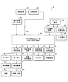
図1は、本発明の実施形態である電子機器としての電子時計1の全体的な構成を示すブロック図である。
FIG. 1 is a block diagram showing an overall configuration of an
この電子時計1は、時刻表示手段として、例えば指針(秒針2、分針3、時針4)を回転させて時刻を表示するアナログ表示部と、文字や記号により時刻やモード情報などを表示する液晶表示部とを有する腕時計である。
The
この電子時計1は、図1に示すように、秒針2と、回転駆動するモーター9と、この回転運動を秒針2に伝達する輪列機構7と、分針3および時針4と、回転駆動するモーター10と、この回転運動を分針3および時針4に伝達する輪列機構8と、モーター9,10の駆動制御を行うモーター制御回路12と、文字や記号の表示を行う液晶表示装置13と、液晶表示装置13の駆動制御を行う表示制御回路14と、標準電波を受信してタイムコードを抽出するアンテナ15および電波受信制御回路16と、アラーム出力を行う報音装置17およびアラーム制御回路18と、電子時計1の統括的な制御を行うマイクロコンピュータ20等を備えている。
As shown in FIG. 1, the
さらに、この電子時計1は、外部から操作指令の入力を行うための操作手段(操作部)26と、所定周期(例えば1Hz)の信号を生成するための発振回路21および分周回路22と、外部光を入射して発電するソーラー電池31と、各部の動作電圧を供給する二次電池33と、ソーラー電池31の電力により二次電池33の充電を行うソーラー充電回路32と、ソーラー電池31の出力の大きさをデジタル値に変換してマイクロコンピュータ20へ供給するA/D変換回路24等を備えている。
Further, the
ソーラー電池31のパネルは、指針(秒針2、分針3、時針4)が回転する文字板上に配設されている。文字板は、電子時計1のケーシングの前面部に風防ガラスに覆われて配設されて外部光が入射されるようになっている。それゆえ、このソーラー電池31の出力(例えば出力電圧)をA/D変換回路24によりデジタル値にして取り込むことで、外部光の強度を測定することが可能になっている。ソーラー電池31とA/D変換回路24により光検出手段が構成される。
The panel of the
操作手段26は、電子時計1のケーシング(機器筐体)の外周部に設けられた複数の操作ボタンを備え、ユーザが操作ボタンを押すことでスイッチ信号が入力されて、マイクロコンピュータ20へ種々の操作指令を送ることが可能になっている。
The operation means 26 includes a plurality of operation buttons provided on the outer peripheral portion of the casing (equipment housing) of the
マイクロコンピュータ20は、制御プログラムを実行するCPU(中央演算処理装置)と、制御プログラムや制御データを格納したROM(Read Only Memory)と、CPUに作業用のメモリ空間を供給するRAM(Random Access Memory)とを備えている。
The
マイクロコンピュータ20のROMには、分周回路22からの信号に基づいて周期的に実行されるメイン制御処理のプログラムや、操作手段26の操作入力に基づいて開始されるキー処理のプログラムなどが格納されている。
The ROM of the
この実施形態の電子時計1においては、上記のメイン制御処理により、周期的に外部光を測定し所定の条件で節電モードへ移行させるモード移行処理が行われるようになっている。
In the
詳細には、特に制限されるものではないが、先ず、通常の機能動作が実行される通常モードにおいて、22時〜6時の夜間に外部光の強度が基準レベル以下となる時間が継続して1時間(第1閾値)を超えた場合に、幾つかの機能動作が禁止される第1節電状態としての第1節電モードへ移行する。また、第1節電モードへ移行した後、外部光の強度が基準レベル以下となる期間が継続して7日間(第2閾値)に達した場合には、多くの機能動作が禁止される第2節電状態としての第2節電モードへと移行する。第1節電モードや第2節電モードの解除は、外部光の強度が基準レベルを超えた場合、或いは、操作手段26の何れかの操作ボタンが押された場合に行われる。 In detail, although not particularly limited, first, in the normal mode in which normal function operation is executed, the time during which the intensity of the external light falls below the reference level continues at night from 22:00 to 6:00. When one hour (first threshold value) is exceeded, the mode shifts to the first power saving mode as the first power saving state in which some functional operations are prohibited. In addition, after the transition to the first power saving mode, when the period in which the intensity of the external light is below the reference level continuously reaches 7 days (second threshold), many functional operations are prohibited. Transition to the second power saving mode as the power saving state. The cancellation of the first power saving mode and the second power saving mode is performed when the intensity of external light exceeds a reference level or when any operation button of the operation means 26 is pressed.
通常モードでは、特に制限されないが、全ての指針(秒針2、分針3、時針4)を動かして時刻を表示する運針処理、所定時刻に標準電波を受信して時刻修正を行う電波受信処理、ユーザが設定した時刻にアラーム音の出力を行うアラーム処理、液晶表示装置13に時刻や動作モードの表示等を行う表示処理が、それぞれ実施される。
In the normal mode, although not particularly limited, a hand movement process that displays the time by moving all the hands (
一方、第1節電モードでは、第1の機能動作として運針処理における秒針2の運針が禁止されて分針3および時針4のみの運針が行われる。また、液晶表示装置13に節電モード中であることを示す「SLEEP」の表示が行われる。
On the other hand, in the first power saving mode, as the first function operation, the
また、第2節電モードでは、第2の機能動作として、所定時刻に標準電波を受信する電波受信処理、設定時刻にアラーム音の出力を行うアラーム処理、および、全指針についての運針処理がそれぞれ禁止され、液晶表示装置13に節電モード中であることを示す「SLEEP」の表示が行われるようになっている。
In the second power saving mode, as the second function operation, radio wave reception processing for receiving a standard radio wave at a predetermined time, alarm processing for outputting an alarm sound at a set time, and hand movement processing for all pointers are prohibited. Then, “SLEEP” is displayed on the liquid
また、この実施形態の電子時計1では、上記のキー処理において、第1節電モードや第2節電モードに切り換える際に参照される光強度の基準レベルを、ユーザが適宜設定変更できるようになっている。具体的には、周囲を光強度の基準レベルとしたい暗さにした状態で、電子時計1の操作手段26により所定の操作入力を行う。このような操作によって、この操作入力時の暗さに近い明るさのレベルが、上記の光強度の基準レベルとして新たに設定されるようになっている。
In the
次に、上記のメイン制御処理とキー処理について、フローチャートを参照しながら詳細に説明する。 Next, the main control process and the key process will be described in detail with reference to flowcharts.
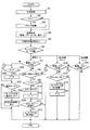
図2は、マイクロコンピュータ20のCPUにより実行されるメイン制御処理の処理手順を示すフローチャートである。
FIG. 2 is a flowchart showing a processing procedure of main control processing executed by the CPU of the
このメイン制御処理は、分周回路22の1Hzの周期信号が入力されるごとに開始される。メイン制御処理が開始されると、先ず、マイクロコンピュータ20のCPUは、RAM中の計時カウンタを1秒分進める(ステップS1)。この計時カウンタは現在時刻をカウントするものである。
This main control process is started each time a 1 Hz periodic signal is input to the
続いて、RAM中の節電移行判断用のカウンタ(計時手段)が計数中か否かを表わすフラグ“F”の値を確認し(ステップS2)、計数中を示す値“1”であれば、節電移行判断用のカウンタを加算して(ステップS3)、次に進む。一方、計数中でないことを示す値“0”であれば、そのまま次に進む。節電移行判断用のカウンタは、暗い状態での経過時間を計数するためのものである。 Subsequently, the value of the flag “F” indicating whether or not the power saving transition counter (time measuring means) in the RAM is counting is checked (step S2). If the value is “1” indicating that counting is in progress, A power saving shift determination counter is added (step S3), and the process proceeds to the next. On the other hand, if the value is “0” indicating that the counting is not in progress, the process proceeds as it is. The power saving transition determination counter is for counting the elapsed time in a dark state.
次に進んだら、CPUは、電子時計1の各種の機能動作を実行させるための各種処理(後に詳述)を行い(ステップS4)、続いて、A/D変換回路24を動作させて外部光の強度を表わすデジタル値を取り込む(ステップS5:監視手段)。
Next, the CPU performs various processes (detailed later) for executing various functional operations of the electronic timepiece 1 (step S4), and then operates the A /
次いで、CPUは、RAM中のモードフラグによる分岐処理を行う(ステップS6)。このモードフラグは、通常モード、第1節電モード、第2節電モードのうち、現在選択されているモードが表わされるフラグである。 Next, the CPU performs a branch process based on the mode flag in the RAM (step S6). This mode flag is a flag representing a currently selected mode among the normal mode, the first power saving mode, and the second power saving mode.
その結果、モードフラグが通常モードを示す値であれば、ステップS7に分岐する。そして、先ず、ステップS5で取り込んだ外部光の強さを表わすデジタル値と、明暗判定用の基準レベルとを比較する(ステップS7)。その結果、基準レベルより外部光が暗かった場合には、計時カウンタの値を確認して現在時刻が22時〜6時の間にあるか判別する(ステップS8)。 As a result, if the mode flag is a value indicating the normal mode, the process branches to step S7. First, the digital value representing the intensity of the external light captured in step S5 is compared with the reference level for light / dark determination (step S7). As a result, when the external light is darker than the reference level, the value of the time counter is checked to determine whether the current time is between 22:00 and 6 o'clock (step S8).
そして、この時間にあれば、節電移行判断用のカウンタの計数状態が示されたフラグ“F”がゼロか判別し(ステップS9)、ゼロであれば、計数を開始するためにこのカウンタをクリアし(ステップS10)、フラグ“F”を計数中を表わす値“1”に更新する(ステップS11)。そして、ステップS12へ移行する。一方、ステップS9の判別で、フラグ“F”がすでに計数中の値“1”であれば、そのままステップS12へジャンプする。 At this time, it is determined whether the flag “F” indicating the counting state of the power saving transition determination counter is zero (step S9). If it is zero, the counter is cleared to start counting. (Step S10), the flag “F” is updated to a value “1” indicating that counting is in progress (Step S11). Then, the process proceeds to step S12. On the other hand, if it is determined in step S9 that the flag “F” is already counted “1”, the process jumps to step S12.
ステップS12へ進んだら、CPUは、節電移行判断用のカウンタの計数値が1時間を超えたか判別し(ステップS12)、超えていれば、第1節電モードへ移行するためにモードフラグを第1節電モードの値に更新する(ステップS13:第1制御手段)。そして、このメイン制御処理の1回分の処理を終了する。一方、1時間を超えていなければ、そのままメイン制御処理を終了する。また、ステップS8の判別で現在時刻が22時〜6時の間にない場合にも、そのままメイン制御処理を終了する。 After proceeding to step S12, the CPU determines whether or not the count value of the power saving transition determination counter has exceeded one hour (step S12), and if so, sets the mode flag to shift to the first power saving mode. The power saving mode value is updated (step S13: first control means). Then, one process of the main control process is terminated. On the other hand, if it does not exceed one hour, the main control process is terminated as it is. Also, if the current time is not between 22:00 and 6 o'clock in the determination in step S8, the main control process is terminated as it is.
つまり、通常モードの際には、このメイン制御処理が周期的に繰り返し実行されることで、ステップS5,S7の処理により、周期的に外部光の強さが測定されて基準レベルより暗いか明るいか判別が行われる。そして、ステップS8〜S11,S2,S3の処理により、所定の時間帯に暗い状態が続いた場合に、節電移行判断用のカウンタによりこの暗い状態の経過時間の計数が行われるようになっている。さらに、ステップS12,S13の処理により、経過時間が1時間を超えたら第1節電モードへ移行する制御が行われるようになっている。 That is, in the normal mode, the main control process is repeatedly executed periodically, so that the intensity of external light is periodically measured and darker or brighter than the reference level by the processes in steps S5 and S7. Is determined. When the dark state continues in a predetermined time zone by the processing of steps S8 to S11, S2, and S3, the elapsed time in the dark state is counted by the power saving transition determination counter. . Furthermore, the process of steps S12 and S13 controls to shift to the first power saving mode when the elapsed time exceeds 1 hour.
ステップS6のモード分岐処理で、モードフラグが第1節電モードを示す値であれば、ステップS14へ分岐する。そして、先ず、CPUは、ステップS5で取り込んだ外部光の強さを表わすデジタル値と、明暗判定用の基準レベルとを比較する(ステップS14)。そして、基準レベルより外部光が暗かった場合には、節電移行判断用のカウンタの計数値が7日を超えているか判別し(ステップS15)、超えていなければ、このままこのメイン制御処理を終了する。超えていれば、第2節電モードへ移行するために、モードフラグを第2節電モードの値に更新し(ステップS16:第2制御手段)、カウンタの計数を停止させるためにフラグ“F”をゼロに更新し(ステップS17)、このメイン制御処理を終了する。 In the mode branch process of step S6, if the mode flag is a value indicating the first power saving mode, the process branches to step S14. First, the CPU compares the digital value representing the intensity of the external light captured in step S5 with the reference level for light / dark determination (step S14). If the external light is darker than the reference level, it is determined whether or not the count value of the power saving transition determination counter exceeds 7 days (step S15). If not, the main control process is terminated. . If exceeded, the mode flag is updated to the value of the second power saving mode in order to shift to the second power saving mode (step S16: second control means), and the flag “F” is set to stop counting of the counter. It is updated to zero (step S17), and this main control process is terminated.
つまり、第1節電モードの際には、メイン制御処理が周期的に繰り返し実行されることで、ステップS5,S14の処理により、周期的に外部光の強さが測定されて基準レベルより暗いか明るいか判別が行われるとともに、ステップS2,S3の処理により、節電移行判断用のカウンタの計数が継続される。そして、ステップS15〜S17の処理により、暗い状態の経過時間が7日を経過した場合に、節電移行判断用のカウンタの計数停止と第2節電モードへ移行する制御が行われるようになっている。 That is, in the first power saving mode, the main control process is periodically executed repeatedly, so that the intensity of external light is periodically measured and darker than the reference level by the processes of steps S5 and S14. Whether it is bright or not is determined, and the counting of the power saving transition determination counter is continued by the processing of steps S2 and S3. Then, by the processing of steps S15 to S17, when the elapsed time in the dark state has passed 7 days, control for stopping the counting of the power saving transition determination counter and shifting to the second power saving mode is performed. .
ステップS6のモード分岐処理で、モードフラグが第2節電モードを示す値であれば、ステップS18へ分岐する。そして、先ず、CPUは、ステップS5で取り込んだ外部光の強さを表わすデジタル値と、明暗判定用の基準レベルとを比較する(ステップS18)。そして、基準レベルより外部光が暗かった場合には、このままこのメイン制御処理を終了する。 In the mode branch process of step S6, if the mode flag is a value indicating the second power saving mode, the process branches to step S18. First, the CPU compares the digital value representing the intensity of the external light captured in step S5 with a reference level for light / dark determination (step S18). When the external light is darker than the reference level, the main control process is terminated as it is.
つまり、第2節電モードの際には、メイン制御処理が周期的に繰り返し実行されることで、ステップS5,S14の処理により、定期的に外部光の強さが測定されて基準レベルより暗いか判別され、節電移行判断用のカウンタの計数は停止されたままにされる。 That is, in the second power saving mode, the main control process is periodically repeated, so that the intensity of the external light is periodically measured and darker than the reference level by the processes of steps S5 and S14. As a result, the counter of the power saving transition determination counter is stopped.
また、通常モード、第1および第2節電モードの各々の場合において、上記のステップS7,S14,S18の明暗判別の処理で、外部光が基準レベルより明るいと判別された場合にはステップS19に移行する。そして、先ず、節電移行判断用のカウンタが計数中であればそれを停止させるために、フラグ“F”が計数中を示す値“1”であるか判別し(ステップS19)、そうであればゼロに更新する(ステップS20)。 Further, in each of the normal mode, the first power saving mode, and the second power saving mode, if it is determined that the external light is brighter than the reference level in the light / dark determination process in steps S7, S14, and S18, the process proceeds to step S19. Transition. First, in order to stop the power saving transition determination counter if counting is in progress, it is determined whether the flag “F” is a value “1” indicating that counting is in progress (step S19). Update to zero (step S20).
続いて、モードフラグを確認して現在が通常モードであるか判別し(ステップS21)、そうでなければ、モードフラグを通常モードの値へ更新し(ステップS22)、停止中の指針を元に戻すために各指針を計時カウンタの値と合致する位置まで駆動する(ステップS23)。そして、このメイン制御処理を終了する。一方、通常モードであれば、そのままこのメイン制御処理を終了する。 Subsequently, the mode flag is checked to determine whether the current mode is the normal mode (step S21). If not, the mode flag is updated to the value of the normal mode (step S22). In order to return, each pointer is driven to a position that matches the value of the time counter (step S23). Then, the main control process ends. On the other hand, in the normal mode, the main control process is terminated as it is.
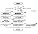
図3には、メイン制御処理(図2)のステップS4で実行される各種処理のフローチャートを示す。 FIG. 3 shows a flowchart of various processes executed in step S4 of the main control process (FIG. 2).
メイン制御処理においてステップS4の各種処理に移行すると、先ず、マイクロコンピュータ20のCPUは、RAM中のモードフラグを確認して、その値に応じた分岐処理を行う(ステップS31)。
When the main control process proceeds to various processes in step S4, the CPU of the
そして、通常モードであれば、ステップS32へ移行して、順次、電波受信処理(ステップS32)、アラーム処理(ステップS33)、全ての指針についての運針処理(ステップS34)、液晶表示装置13の表示処理(ステップS35)を行う。そして、この各種処理を終了して、メイン制御処理(図2)の次のステップへ移行する。
If the current mode is the normal mode, the process proceeds to step S32 to sequentially perform radio wave reception processing (step S32), alarm processing (step S33), hand movement processing for all hands (step S34), and display on the liquid
上記ステップS32の電波受信処理は、標準電波の受信を開始する所定時刻になるのを監視するとともに、この時刻になったら電波受信制御回路16を作動させて標準電波を受信させ、タイムコードから時刻情報を取得してRAM中の計時カウンタの値を修正する処理である。ステップS33のアラーム処理は、ユーザにより設定された時刻になるのを監視するとともに、この時刻になったらアラーム制御回路18にコマンドを送って報音装置17からアラーム出力を行わせる処理である。ステップS34の運針処理は、例えば、秒針2については1秒ごとにモーター9を1ステップ駆動して運針させるとともに、分針3および時針4については10秒ごとにモーター10を1ステップ駆動して運針させる処理である。ステップS35の表示処理は、液晶表示装置13に時刻や種々の情報を表示させる処理である。上記各ステップの処理は1秒ごとに繰り返し実行されて上記のような内容の処理を実現する。
In the radio wave reception process in step S32, the reception of the standard radio wave is monitored, and the radio wave
一方、第1節電モードであれば、ステップS31の分岐処理でステップS36に移行する。そして、CPUは、順次、電波受信処理(ステップS36)、アラーム処理(ステップS37)、分針3と時針4のみについての運針処理(ステップS38)、液晶表示装置13の表示処理(ステップS39)を行う。そして、この各種処理を終了して、メイン制御処理(図2)の次のステップへ移行する。
On the other hand, if it is 1st power saving mode, it will transfer to step S36 by the branch process of step S31. Then, the CPU sequentially performs radio wave reception processing (step S36), alarm processing (step S37), hand movement processing for only the
上記ステップS36,S37の電波受信処理とアラーム処理は、通常モードのステップS32,S33と同一内容の処理である。ステップS38の運針処理は、秒針2については所定位置(例えばゼロ秒位置)に達するまでモーター9を1秒ごとに1ステップずつ駆動するとともに、所定位置に達したあとはモーター9の駆動を停止させる処理である。また、分針3と時針4については通常通りモーター10を10秒ごとに1ステップずつ駆動する。ステップS39の表示処理は、液晶表示装置13に節電モード中であることを示す文字「SLEEP」を表示する処理である。
The radio wave reception process and the alarm process in steps S36 and S37 are the same processes as steps S32 and S33 in the normal mode. In step S38, the
また、第2節電モードであれば、ステップS31の分岐処理でステップS40に移行して、液晶表示装置13に節電モード中であることを示す文字「SLEEP」を表示する処理(ステップS40)を行う。そして、この各種処理を終了して、メイン制御処理(図2)の次のステップへ移行する。 If the current mode is the second power saving mode, the process proceeds to step S40 in the branch process of step S31, and the character “SLEEP” indicating the power saving mode is displayed on the liquid crystal display device 13 (step S40). . Then, the various processes are terminated, and the process proceeds to the next step of the main control process (FIG. 2).
このような各種処理により、第1節電モードになると秒針2の運針が禁止され、第2節電モードになると電波受信処理、アラーム処理および全ての指針の運針処理がそれぞれ禁止されるようになっている。また、第1および第2節電モードの際には、液晶表示装置13の通常時の表示が行われずに、節電モードを示す表示がなされるようになっている。
By such various processes, the
図4には、マイクロコンピュータ20のCPUにより実行されるキー処理のフローチャートを示す。
FIG. 4 shows a flowchart of key processing executed by the CPU of the
キー処理は、ユーザが操作手段26の操作ボタンを操作して、CPUにキー入力に基づく割込みが発生した場合に開始される処理である。キー処理が開始されると、先ず、マイクロコンピュータ20のCPUは、節電移行判断用のカウンタが計数中か否かを示すフラグ“F”の値を確認し(ステップS51)、計数中を示す値“1”であれば、計数を中止させるためにゼロに更新する(ステップS52)。
The key process is a process started when the user operates the operation button of the
次いで、キー入力の内容を確認し、明暗判定用の基準レベルを設定変更するためのスリープ操作の入力であるか否かを判別する(ステップS53)。そして、スリープ操作の入力であれば、基準値セット処理(ステップS55:設定手段)を実行し、その他の操作入力であれば各操作入力に対応した処理を行う他のスイッチ処理(ステップS54)を実行する。そして、次に移行する。 Next, the contents of the key input are confirmed, and it is determined whether or not the input is a sleep operation for changing the setting of the reference level for light / dark determination (step S53). If the input is a sleep operation, the reference value setting process (step S55: setting means) is executed, and if it is another operation input, another switch process (step S54) that performs a process corresponding to each operation input is performed. Execute. And it shifts to the next.
次に移行したら、マイクロコンピュータ20のCPUは、RAM中のモードフラグを確認して通常モードの値であるか否かを判別する(ステップS56)。そして、通常モードの値であれば、そのままキー処理を終了する一方、第1又は第2節電モードの値であればモードフラグを通常モードの値に更新し(ステップS57)、第1又は第2節電モードで停止させていた指針を駆動して計時カウンタの現在の計時時刻に戻す処理(ステップS58)を行って、このキー処理を終了する。
When the next transition is made, the CPU of the
このようなキー処理により、ユーザが操作手段26の操作ボタンを操作した場合に、その操作内容に応じた処理が実行されるとともに、節電移行判断用のカウンタが計数中であればこの計数が停止され、また、第1又は第2節電モードである場合には通常モードに復帰するようになっている。 By such key processing, when the user operates the operation button of the operation means 26, processing according to the operation content is executed, and if the power saving shift determination counter is counting, this counting is stopped. In addition, in the first or second power saving mode, the normal mode is restored.
図5には、キー処理(図4)のステップS55で実行される基準値セット処理のフローチャートを、図6には、基準値セット処理で使用される光レベルのA/D変換値が登録されたデータテーブルを示す。 FIG. 5 shows a flowchart of the reference value setting process executed in step S55 of the key process (FIG. 4), and FIG. 6 shows the A / D conversion value of the light level used in the reference value setting process. Shows the data table.
基準値セット処理に移行すると、マイクロコンピュータ20のCPUは、先ず、作業用の光レベルSUN_LVの変数値に初期値“1”をセットする(ステップS61)。
After shifting to the reference value setting process, the CPU of the
図6に示すように、マイクロコンピュータ20のROMには、光レベルSUN_LVの変数値“1〜15”と、これらの値に対応した光の参照レベルをそれぞれ表わすA/D変換値とが登録されているデータテーブル41が、制御データとして格納されている。
As shown in FIG. 6, in the ROM of the
このデータテーブル41のA/D変換値は、ソーラー電池31とA/D変換回路24による外部光の測定値、すなわち、外部光によるソーラー電池31の出力のA/D変換値と比較可能なように、光の強度をA/D変換回路のA/D変換値に換算した値となっている。
The A / D conversion values in the data table 41 can be compared with the measured values of the external light by the
データテーブル41のA/D変換値は、光レベルSUN_LVの変数値が小さければ暗い値に、光レベルSUN_LVの変数値が大きくなるほど明るい値になるように設定されている。これらの値は、例えば、細かな設定が要求される明るさの範囲(例えば薄明かりの範囲)では細かな間隔で値が登録され、細かな設定が要求されない明るさの範囲(例えば照明下の明るさ以上の範囲)では大まかな間隔で値が登録されている。 The A / D conversion values in the data table 41 are set to be darker when the variable value of the light level SUN_LV is smaller and brighter as the variable value of the light level SUN_LV is larger. These values are registered at fine intervals, for example, in a brightness range where a fine setting is required (for example, a low light range), and a brightness range where a fine setting is not required (for example, under illumination) In the range above the brightness, values are registered at rough intervals.
図5のステップS61で光レベルSUN_LVの変数値に初期値をセットしたら、次に、マイクロコンピュータ20のCPUは、A/D変換回路24を作動させて外部光の明るさを表わすデジタル値を取り込む(ステップS62)。
After the initial value is set as the variable value of the light level SUN_LV in step S61 in FIG. 5, the CPU of the
なお、ステップS62の外部光の明るさの取り込みは、ステップS62〜S65のループ処理に組み入れずに、ステップS65の判別処理で“NO”と判定されたらステップS63に戻るようにして、1回のみ実行されるようにしても良い。 Note that the brightness of the external light in step S62 is not included in the loop processing in steps S62 to S65, and returns to step S63 only once when it is determined “NO” in the determination processing in step S65. It may be executed.
そして、光レベルSUN_LVの変数値に対応するデータテーブル41のA/D変換値と、ステップS62で取り込んだデジタル値とを比較して、外部光の方が明るいか否かを判別する(ステップS63:比較手段)。その結果、ステップS62で取り込んだデジタル値の方が大きく、外部光の方が明るければ、光レベルSUN_LVの変数値を「1」加算し(ステップS64)、光レベルSUN_LVの変数値が最大値を超えた値“0xF(十進数で16)”になったか判別する(ステップS65)。そして、未だ、最大値を超えていなければステップS62に戻る。 Then, the A / D conversion value of the data table 41 corresponding to the variable value of the light level SUN_LV is compared with the digital value acquired in step S62 to determine whether or not the external light is brighter (step S63). : Comparison means). As a result, if the digital value captured in step S62 is larger and the external light is brighter, the variable value of the light level SUN_LV is incremented by “1” (step S64), and the variable value of the light level SUN_LV reaches the maximum value. It is determined whether or not the excess value is “0xF (decimal 16)” (step S65). If the maximum value has not been exceeded, the process returns to step S62.
上記のステップS62〜S65のループ処理が繰り返されることで、データテーブル41の登録データに基づいて光レベルSUN_LVが暗い方から明るい方へシフトされながら、順に、外部光との強度比較が行われていく。そして、外部光の方が明るいまま、光レベルSUN_LVの変数値が最大値を超えた場合には、ステップS65の判別処理で“Yes”側へ進んで、明暗判定の基準レベルの設定は不可であるためエラー処理を行う(ステップS68)。そして、この基準値セット処理を終了する。 By repeating the loop processing of steps S62 to S65 described above, the light level SUN_LV is shifted from the darker to the brighter based on the registered data in the data table 41, and the intensity comparison with the external light is sequentially performed. Go. If the variable value of the light level SUN_LV exceeds the maximum value while the external light is brighter, the process proceeds to “Yes” in the determination process in step S65, and the reference level for the light / dark determination cannot be set. Therefore, error processing is performed (step S68). Then, the reference value setting process ends.
一方、光レベルSUN_LVの変数値が最大値を超える前に、ステップS63で外部光の方が暗いと判別された場合には、その1段階前の光レベルSUN_LVを明暗判定用の基準レベルとするため、現在の光レベルSUN_LVの変数値を「1」減算する(ステップS66)。そして、この変数値が最小値「1」を下回る値「0」になっていないか確認し(ステップS67)、下回る値になっていなければ、この光レベルSUN_LVの値を明暗判定用の基準レベルJUDGE_LVとして設定する(ステップS69)。そして、この基準値セット処理を終了する。 On the other hand, if it is determined in step S63 that the external light is darker before the variable value of the light level SUN_LV exceeds the maximum value, the light level SUN_LV one step before is set as a reference level for light / dark determination. Therefore, “1” is subtracted from the variable value of the current light level SUN_LV (step S66). Then, it is confirmed whether or not the variable value has become a value “0” that is less than the minimum value “1” (step S67). This is set as JUDGE_LV (step S69). Then, the reference value setting process ends.
一方、ステップS67の確認処理で、光レベルSUN_LVの変数値が最小値を下回る値「0」になっていれば、明暗判定の基準レベルの設定は不可であるためエラー処理を行って(ステップS70)、この基準値セット処理を終了する。 On the other hand, if the variable value of the light level SUN_LV is “0” below the minimum value in the confirmation processing in step S67, the reference level for the light / dark determination cannot be set, and error processing is performed (step S70). ), The reference value setting process is terminated.
つまり、上記の基準値セット処理により、ユーザは、電子時計1を節電モードに移行させたくないぎりぎりの明るさのところに置いて、設定処理を開始するスリープ操作を行うことで、図6のデータテーブル41に登録されている複数の光レベルSUN_LVの中から現在の外部光の強度を下回り且つ現在の外部光に一番近いレベルが抽出されて、そのA/D変換値が明暗判定の基準レベルとして新たに設定されるようになっている。
That is, by the reference value setting process described above, the user places the
以上のように、この実施形態の電子時計1によれば、第1節電モード又は第2節電モードへ移行させる条件判断に使用される明暗判定の基準レベルを、ユーザによる操作手段26の操作によって設定変更することができる。従って、ユーザが適宜な設定を行うことにより、ユーザ毎の使用状況にそれぞれ適応した節電モードへの移行処理を実現できる。
As described above, according to the
また、上記明暗判定の基準レベルは、操作手段26の操作の際の外部光の測定値に基づいて決定されるので、ユーザは、外部光を明暗判定の基準レベルとしたい明るさに近づけ、この状態で操作手段26の操作を行うことで、容易に明暗判定の基準レベルを適切な値に設定することができる。 In addition, since the reference level for the light / dark determination is determined based on the measured value of the external light when the operation means 26 is operated, the user can bring the external light close to the brightness that is desired to be the reference level for the light / dark determination. By operating the operating means 26 in the state, the reference level for light / dark judgment can be easily set to an appropriate value.
また、この実施形態の電子時計1によれば、ソーラー電池31の出力をA/D変換して取り込むことで外部光の強度を検出する構成なので、発電用と外部光強度の検出用とで素子を兼用させて、外部光強度の検出専用の素子の実装を省くことができる。
In addition, according to the
また、この実施形態の電子時計1によれば、データテーブル41に予め登録されている複数の光レベルSUN_LVと外部光の強度とを比較して、その比較結果に応じてデータテーブル41に登録されている複数の光レベルSUN_LVの中から明暗判定用の基準レベルを選択的に設定するようになっている。従って、このデータテーブル41の光レベルSUN_LVを適宜な間隔で登録しておくことで、明暗判定用の基準レベルを適宜なステップ幅で設定変更させることが可能となる。
Further, according to the
また、この実施形態の電子時計1によれば、周期的に外部光の強さを取り込んで、所定の時間帯に基準レベルを下回っていたら節電移行判断用のカウンタを動作させ、基準レベルを超えずに1時間を経過したら秒針2の運針が禁止される第1節電モードへ移行する。さらに、7日を経過したら標準電波の受信、アラーム機能、全ての指針の運針が禁止される第2節電モードへ移行するとともに、節電移行判断用のカウンタも停止されるようになっている。従って、ユーザにより設定された明暗判定用の基準レベルにより、有効な節電モードへの移行処理が実現される。
In addition, according to the
また、明暗判定の基準レベルを設定する際には、電子時計1のケーシングの外周部に設けられた操作ボタンを操作することで基準値セット処理に移行できるので、ユーザは容易に明暗判定用の基準レベルの設定変更を行うことができる。なお、誤操作により間違って基準レベルが設定変更されてしまうのを防ぐために、基準値セット処理を開始させる操作パターンを、複数の操作ボタンの入力を必要としたり操作ボタンの長押しを必要としたりするなど特殊な操作パターンとしても良い。
Further, when setting the reference level for the light / dark determination, the user can easily shift to the reference value setting process by operating an operation button provided on the outer peripheral portion of the casing of the
なお、本発明は、上記実施の形態に限られるものではなく、様々な変更が可能である。例えば、上記実施形態では、電子機器として電子時計に本発明を適用した例を示したが、携帯電話、PDA(Personal Digital Assistant)、デジタルカメラ、携帯音楽プレーヤなど、種々の電子機器に本発明を同様に適用することができる。節電モードで禁止される機能動作も、電子時計における電波受信処理、アラーム処理および運針処理に制限されず、表示装置のバックライトの発光、表示装置の表示出力、音楽再生など、種々の機能動作が適用可能である。 The present invention is not limited to the above-described embodiment, and various modifications can be made. For example, in the above embodiment, an example in which the present invention is applied to an electronic watch as an electronic device has been shown. However, the present invention is applied to various electronic devices such as a mobile phone, a PDA (Personal Digital Assistant), a digital camera, and a portable music player. The same can be applied. Functional operations that are prohibited in the power saving mode are not limited to radio wave reception processing, alarm processing, and hand movement processing in an electronic watch, and various functional operations such as backlight emission of the display device, display output of the display device, and music playback are possible. Applicable.
また、上記実施形態では、外部光を検出する光検出手段として、ソーラー電池を利用した構成を示したが、専用の光センサを設けるようにしても良い。 In the above embodiment, a configuration using a solar battery is shown as the light detection means for detecting external light. However, a dedicated light sensor may be provided.
また、上記実施形態では、節電モードから通常モードへ復帰する条件に、基準レベル以上の光の検出という条件が含まれているが、節電モードへ移行する際の明暗判定に使用される基準レベルと、通常モードへ復帰する際の明暗判定に使用される光レベルと、それぞれ別のレベルにしても良い。その他、通常モードへ復帰する条件は、特に制限されるものでなく、装置の振動や姿勢変化等を検出して通常モードへ復帰させるなど、種々の条件を適用しても良い。 Further, in the above embodiment, the condition for returning from the power saving mode to the normal mode includes the condition of detecting light above the reference level, but the reference level used for light / dark judgment when shifting to the power saving mode The light level used for the light / dark judgment when returning to the normal mode may be set to a different level. In addition, the conditions for returning to the normal mode are not particularly limited, and various conditions may be applied such as detecting vibrations of the apparatus, changes in posture, etc. to return to the normal mode.
また、上記実施形態では、節電モードへ移行する際の明暗判定に使用される基準レベルを一種類としているが、例えば昼と夜など時間帯に応じて複数種類の基準レベルを用いるようにしても良く、この場合、複数種類の基準レベルを、ユーザの操作入力によってそれぞれ同様に設定変更できるように構成しても良い。 Moreover, in the said embodiment, although the reference level used for the light / dark judgment at the time of shifting to power saving mode is made into one type, it may be made to use several types of reference levels according to time zones, such as day and night, for example. In this case, a plurality of types of reference levels may be configured to be similarly changed by user operation input.
また、上記実施形態では、操作手段26の操作時点における外部光の測定強度に基づいて基準レベルを設定するようにしているが、本発明では、例えば、操作手段26の操作時点から例えば10秒後など所定数秒後における外部光の測定強度に基づいて基準レベルを設定するようにしても良い。このように構成することで、例えば、ひき出しの中に閉まった状態の外部光の強度に基づいて基準レベルを設定することも可能となる。 In the above embodiment, the reference level is set based on the measured intensity of the external light at the time of operation of the operation means 26. However, in the present invention, for example, 10 seconds after the operation time of the operation means 26, for example. For example, the reference level may be set based on the measured intensity of external light after a predetermined number of seconds. With this configuration, for example, it is possible to set the reference level based on the intensity of the external light that is closed in the drawer.
また、上記実施形態では、外部光の測定強度をデータテーブル41(図6)に登録されている複数個の光レベルと比較して、その比較結果に応じてデータテーブルに登録されている複数個の光レベルの中から基準レベルを設定するようにしているが、外部光の測定強度をそのまま基準レベルに設定したり、測定強度から所定量を増減させた値を基準レベルに設定したりしても良い。 Further, in the above embodiment, the measured intensity of external light is compared with a plurality of light levels registered in the data table 41 (FIG. 6), and a plurality of registered in the data table according to the comparison result. The reference level is set from among the light levels, but the measurement intensity of external light is set to the reference level as it is, or a value obtained by increasing or decreasing a predetermined amount from the measurement intensity is set as the reference level. Also good.
その他、実施形態で示した細部等は発明の趣旨を逸脱しない範囲で適宜変更可能である。 In addition, the details shown in the embodiments can be appropriately changed without departing from the spirit of the invention.
1 電子時計
2 秒針
3 分針
4 時針
9,10 モーター
13 液晶表示装置
16 電波受信制御回路
17 報音装置
18 アラーム制御回路
20 マイクロコンピュータ
24 A/D変換回路
26 操作手段
31 ソーラー電池
41 データテーブル
DESCRIPTION OF
Claims (5)
外部からの操作入力が可能な操作部と、
この操作部の操作入力の際に前記光検出手段により検出された光の強さに基づいて前記基準レベルを設定する設定手段と、
を備えたことを特徴とする電子機器。 In an electronic device that shifts to a power-saving state in which operation of a predetermined function is prohibited when detection of light below a reference level is continued for a predetermined time by a light detection unit that detects external light,
An operation unit that allows external operation input,
Setting means for setting the reference level based on the intensity of light detected by the light detection means at the time of operation input of the operation unit;
An electronic device characterized by comprising:
外部光を入射して発電するソーラー電池の出力の大きさを測って外部光の強さを検出する構成であることを特徴とする請求項1記載の電子機器。 The light detection means includes
2. The electronic apparatus according to claim 1, wherein the intensity of the external light is detected by measuring the output of a solar battery that generates power upon incidence of external light.
前記設定手段は、
前記複数種類の参照レベルの中から前記比較手段の比較結果に応じて選択された1個の参照レベルを前記基準レベルとして設定する
ことを特徴とする請求項1記載の電子機器。 Comparing means for comparing the light intensity detected by the light detecting means with a plurality of predetermined reference levels;
The setting means includes
The electronic apparatus according to claim 1, wherein one reference level selected from the plurality of types of reference levels according to a comparison result of the comparison unit is set as the reference level.
この監視手段により監視された光の強さが基準レベル以下になったことに基づき計時が開始される計時手段と、
前記監視手段により監視された光の強さが前記基準レベル以下のまま前記計時手段が第1閾値を超えたら第1の機能動作が禁止される第1節電状態へ移行させる第1制御手段と、
前記監視手段により監視された光の強さが前記基準レベル以下のまま前記計時手段が前記第1閾値より大きな第2閾値を超えたら前記計時手段の計時を停止させるとともに、前記第1の機能動作に加えて第2の機能動作が禁止される第2節電状態へ移行させる第2制御手段と、
を備えていることを特徴とする請求項1記載の電子機器。 Monitoring means for periodically monitoring the intensity of light detected by the light detection means;
Timing means for starting timing based on the fact that the intensity of light monitored by the monitoring means is below a reference level;
First control means for shifting to a first power-saving state in which the first functional operation is prohibited when the timing means exceeds a first threshold while the intensity of light monitored by the monitoring means is below the reference level;
If the light intensity monitored by the monitoring means is below the reference level and the time measuring means exceeds a second threshold value greater than the first threshold value, the time measuring means stops timing and the first functional operation In addition to the second control means for shifting to the second power saving state in which the second functional operation is prohibited,
The electronic apparatus according to claim 1, further comprising:
前記操作部は、前記機器筐体の外周部に設けられた操作ボタンにより操作入力が行われる構成であることを特徴とする請求項1記載の電子機器。 It has time display means for displaying the time on the front part of the equipment housing,
The electronic device according to claim 1, wherein the operation unit has a configuration in which an operation input is performed by an operation button provided on an outer peripheral portion of the device housing.
Priority Applications (1)
| Application Number | Priority Date | Filing Date | Title |
|---|---|---|---|
| JP2010140271A JP2012002767A (en) | 2010-06-21 | 2010-06-21 | Electronic apparatus |
Applications Claiming Priority (1)
| Application Number | Priority Date | Filing Date | Title |
|---|---|---|---|
| JP2010140271A JP2012002767A (en) | 2010-06-21 | 2010-06-21 | Electronic apparatus |
Publications (2)
| Publication Number | Publication Date |
|---|---|
| JP2012002767A true JP2012002767A (en) | 2012-01-05 |
| JP2012002767A5 JP2012002767A5 (en) | 2013-05-30 |
Family
ID=45534899
Family Applications (1)
| Application Number | Title | Priority Date | Filing Date |
|---|---|---|---|
| JP2010140271A Pending JP2012002767A (en) | 2010-06-21 | 2010-06-21 | Electronic apparatus |
Country Status (1)
| Country | Link |
|---|---|
| JP (1) | JP2012002767A (en) |
Cited By (10)
| Publication number | Priority date | Publication date | Assignee | Title |
|---|---|---|---|---|
| JP2015525879A (en) * | 2012-07-18 | 2015-09-07 | ウーテーアー・エス・アー・マニファクチュール・オロロジェール・スイス | Improved method of managing electronic devices |
| JP2015175764A (en) * | 2014-03-17 | 2015-10-05 | シチズンホールディングス株式会社 | Electronic clock |
| EP2743796A3 (en) * | 2012-12-11 | 2017-01-18 | Samsung Electronics Co., Ltd | Electronic apparatus, method of controlling the same, and computer-readable recording medium |
| JP2017096776A (en) * | 2015-11-25 | 2017-06-01 | シチズン時計株式会社 | Electronic watch |
| JP2018077252A (en) * | 2018-01-16 | 2018-05-17 | シチズン時計株式会社 | Electronic clock |
| JP2019149825A (en) * | 2019-04-17 | 2019-09-05 | 京セラ株式会社 | Electronic device, program, and control method |
| JP2020170014A (en) * | 2020-07-01 | 2020-10-15 | カシオ計算機株式会社 | Electronic device, power supply control method, and program |
| JP2021032585A (en) * | 2019-08-19 | 2021-03-01 | シチズン時計株式会社 | Electronic watch |
| US11269417B2 (en) | 2016-11-15 | 2022-03-08 | Kyocera Corporation | Electronic device configured to communicate with an intercom, and control method thereof |
| US11906936B2 (en) | 2018-03-08 | 2024-02-20 | Casio Computer Co., Ltd. | Electronic apparatus, power feeding control method, and non-transitory recording medium |
Citations (4)
| Publication number | Priority date | Publication date | Assignee | Title |
|---|---|---|---|---|
| JP2000230988A (en) * | 1998-12-10 | 2000-08-22 | Seiko Epson Corp | Portable electronic apparatus, control method therefor, and clocking apparatus and control method therefor |
| WO2001098843A1 (en) * | 2000-06-21 | 2001-12-27 | Citizen Watch Co.,Ltd. | Power generating type electronic clock and method for controlling the same |
| WO2002019041A1 (en) * | 2000-08-31 | 2002-03-07 | Citizen Watch Co.,Ltd. | Electronic clock |
| JP2010117286A (en) * | 2008-11-14 | 2010-05-27 | Casio Computer Co Ltd | Electronic timepiece |
-
2010
- 2010-06-21 JP JP2010140271A patent/JP2012002767A/en active Pending
Patent Citations (4)
| Publication number | Priority date | Publication date | Assignee | Title |
|---|---|---|---|---|
| JP2000230988A (en) * | 1998-12-10 | 2000-08-22 | Seiko Epson Corp | Portable electronic apparatus, control method therefor, and clocking apparatus and control method therefor |
| WO2001098843A1 (en) * | 2000-06-21 | 2001-12-27 | Citizen Watch Co.,Ltd. | Power generating type electronic clock and method for controlling the same |
| WO2002019041A1 (en) * | 2000-08-31 | 2002-03-07 | Citizen Watch Co.,Ltd. | Electronic clock |
| JP2010117286A (en) * | 2008-11-14 | 2010-05-27 | Casio Computer Co Ltd | Electronic timepiece |
Cited By (12)
| Publication number | Priority date | Publication date | Assignee | Title |
|---|---|---|---|---|
| JP2015525879A (en) * | 2012-07-18 | 2015-09-07 | ウーテーアー・エス・アー・マニファクチュール・オロロジェール・スイス | Improved method of managing electronic devices |
| EP2743796A3 (en) * | 2012-12-11 | 2017-01-18 | Samsung Electronics Co., Ltd | Electronic apparatus, method of controlling the same, and computer-readable recording medium |
| JP2015175764A (en) * | 2014-03-17 | 2015-10-05 | シチズンホールディングス株式会社 | Electronic clock |
| JP2017096776A (en) * | 2015-11-25 | 2017-06-01 | シチズン時計株式会社 | Electronic watch |
| US11269417B2 (en) | 2016-11-15 | 2022-03-08 | Kyocera Corporation | Electronic device configured to communicate with an intercom, and control method thereof |
| JP2018077252A (en) * | 2018-01-16 | 2018-05-17 | シチズン時計株式会社 | Electronic clock |
| US11906936B2 (en) | 2018-03-08 | 2024-02-20 | Casio Computer Co., Ltd. | Electronic apparatus, power feeding control method, and non-transitory recording medium |
| JP2019149825A (en) * | 2019-04-17 | 2019-09-05 | 京セラ株式会社 | Electronic device, program, and control method |
| JP2021032585A (en) * | 2019-08-19 | 2021-03-01 | シチズン時計株式会社 | Electronic watch |
| JP7288369B2 (en) | 2019-08-19 | 2023-06-07 | シチズン時計株式会社 | electronic clock |
| JP2020170014A (en) * | 2020-07-01 | 2020-10-15 | カシオ計算機株式会社 | Electronic device, power supply control method, and program |
| JP7099492B2 (en) | 2020-07-01 | 2022-07-12 | カシオ計算機株式会社 | Electronic devices, power supply control methods, and programs |
Similar Documents
| Publication | Publication Date | Title |
|---|---|---|
| JP2012002767A (en) | Electronic apparatus | |
| JP5343521B2 (en) | Electronic clock | |
| JP6960990B2 (en) | Analog electronic clock system and analog electronic clock | |
| JP5294621B2 (en) | Electronics | |
| US20190227497A1 (en) | Analog electronic watch system and analog electronic watch | |
| JP4724446B2 (en) | Electronic device and display control method | |
| JP6402664B2 (en) | Electronic device and method for initializing control means of electronic device | |
| JP5310578B2 (en) | Electronic equipment with power generation function | |
| JP6204855B2 (en) | Electronics | |
| US11385600B2 (en) | Timer measurement device, electronic timepiece, timer measurement method, and non-transitory computer readable storage medium storing program | |
| JP5251998B2 (en) | Electronic clock | |
| JP2017166931A (en) | Electronic clock and additional function control system | |
| JP2005308396A (en) | Electronic timepiece, control method of the same, program and recording medium | |
| US10222762B2 (en) | Method of managing an electronic apparatus | |
| JP6792498B2 (en) | Analog electronic clock system and analog electronic clock | |
| JP4647773B2 (en) | Electronic clock | |
| JP5215689B2 (en) | Pointer type display device | |
| JPH0627255A (en) | Electronic timepiece | |
| JP2000356690A (en) | Electronic clock and method of controlling the electronic clock | |
| JP3252659B2 (en) | Electronic clock with alarm and setting method of alarm time | |
| EP0689110B1 (en) | Apparatus and method for setting a value to be displayed | |
| JP2022070680A (en) | Electronic watch | |
| JP2022072726A (en) | Electronic timepiece and method for display of electronic timepiece | |
| JP6020133B2 (en) | Electronic device with power generation function and control method of electronic device with power generation function | |
| JP2009162553A (en) | Electronic timepiece |
Legal Events
| Date | Code | Title | Description |
|---|---|---|---|
| A521 | Written amendment |
Free format text: JAPANESE INTERMEDIATE CODE: A523 Effective date: 20130417 |
|
| A621 | Written request for application examination |
Free format text: JAPANESE INTERMEDIATE CODE: A621 Effective date: 20130417 |
|
| RD02 | Notification of acceptance of power of attorney |
Free format text: JAPANESE INTERMEDIATE CODE: A7422 Effective date: 20130417 |
|
| A977 | Report on retrieval |
Free format text: JAPANESE INTERMEDIATE CODE: A971007 Effective date: 20130807 |
|
| A131 | Notification of reasons for refusal |
Free format text: JAPANESE INTERMEDIATE CODE: A131 Effective date: 20130820 |
|
| A521 | Written amendment |
Free format text: JAPANESE INTERMEDIATE CODE: A523 Effective date: 20131017 |
|
| A02 | Decision of refusal |
Free format text: JAPANESE INTERMEDIATE CODE: A02 Effective date: 20140311 |