JP2012002136A - Vane type rotating device - Google Patents
Vane type rotating device Download PDFInfo
- Publication number
- JP2012002136A JP2012002136A JP2010137858A JP2010137858A JP2012002136A JP 2012002136 A JP2012002136 A JP 2012002136A JP 2010137858 A JP2010137858 A JP 2010137858A JP 2010137858 A JP2010137858 A JP 2010137858A JP 2012002136 A JP2012002136 A JP 2012002136A
- Authority
- JP
- Japan
- Prior art keywords
- fluid
- port
- back pressure
- vane
- pressure
- Prior art date
- Legal status (The legal status is an assumption and is not a legal conclusion. Google has not performed a legal analysis and makes no representation as to the accuracy of the status listed.)
- Pending
Links
Images


Landscapes
- Rotary Pumps (AREA)
Abstract
【課題】ベーンの位置に関わりなく、ベーンの先端とカムリングとの摩擦力を同程度にすることができるベーン型回転装置を提供する
【解決手段】隣接する二つの分割室23が第一ポート151aから流体を供給されている場合の当該二つの分割室23を区画する供給側のベーン13bの背圧と、隣接する二つの分割室23が第二ポート151bへ流体を排出している場合の当該二つの分割室23を区画する排出側のベーン13dの背圧と、隣接する一方の分割室23が第一ポート151aから流体を供給され他方の分割室23が第二ポート151bに流体を排出している場合の当該二つの分割室23を区画する中間のベーン13a,13c,13eの背圧とをそれぞれ異なる圧力とする。
【選択図】図5To provide a vane-type rotating device capable of making the frictional force between the tip of the vane and the cam ring the same regardless of the position of the vane. When the fluid is supplied from the back pressure of the vane 13b on the supply side that divides the two divided chambers 23, and when the adjacent two divided chambers 23 discharge the fluid to the second port 151b The back pressure of the discharge side vane 13d that divides the two divided chambers 23, one adjacent divided chamber 23 is supplied with fluid from the first port 151a, and the other divided chamber 23 discharges fluid to the second port 151b. The back pressures of the intermediate vanes 13a, 13c, 13e dividing the two divided chambers 23 are different from each other.
[Selection] Figure 5
Description
本発明は、ベーン型モータおよびベーン型ポンプなどのベーン型回転装置に関するものである。 The present invention relates to a vane type rotating device such as a vane type motor and a vane type pump.
ベーン型回転装置について、例えば、特開2001−248569号公報(特許文献1)に記載されたものがある。特許文献1に記載のベーン型回転装置においては、各ベーンの背圧は、高圧ポートの流体が供給されている。つまり、各ベーンの背圧は、一定となっている。 An example of the vane-type rotating device is described in Japanese Patent Application Laid-Open No. 2001-248569 (Patent Document 1). In the vane type rotating device described in Patent Document 1, the back pressure of each vane is supplied with the fluid of the high pressure port. That is, the back pressure of each vane is constant.
ここで、ベーン型回転装置において、ベーンの先端とカムリングのカム形状の内周面とは摺動するため、ベーンとカムリングとの摩擦力が発生する。この摩擦力が大きいと、ベーン型回転装置のトルク効率を低下する原因となる。そして、上述した特許文献1に記載のベーン型回転装置においては、各ベーンの背圧は一定であるため、カムリングとロータとにより形成される径方向隙間をベーンによって周方向に分割される分割室における流体の圧力が低い部分に位置するベーンは、当該分割室の流体により押し戻される力に比べてベーンの背圧の方が非常に大きくなる。その結果、ベーンの先端とカムリングとの摩擦力が大きくなり、トルク効率の低下することになる。 Here, in the vane type rotating device, since the tip of the vane and the cam-shaped inner peripheral surface of the cam ring slide, a frictional force is generated between the vane and the cam ring. When this frictional force is large, it causes a reduction in torque efficiency of the vane type rotating device. In the vane-type rotating device described in Patent Document 1 described above, since the back pressure of each vane is constant, the radial chamber formed by the cam ring and the rotor is divided in the circumferential direction by the vane. In the vane located in the portion where the fluid pressure is low, the back pressure of the vane is much larger than the force pushed back by the fluid in the divided chamber. As a result, the frictional force between the tip of the vane and the cam ring increases, and the torque efficiency decreases.
これに対して、特開2004−232465号公報(特許文献2)に記載されたベーン型回転装置は、高圧ポートが形成される位相範囲と、高圧ポートと低圧ポートとの間の切換位相範囲とにおいて、ベーンの背圧を高圧とし、低圧ポートが形成される位相範囲においてベーンの背圧を低圧とするとされている。 On the other hand, the vane type rotating device described in Japanese Patent Application Laid-Open No. 2004-232465 (Patent Document 2) includes a phase range in which a high pressure port is formed, and a switching phase range between the high pressure port and the low pressure port. The vane back pressure is set to a high pressure, and the vane back pressure is set to a low pressure in a phase range in which a low pressure port is formed.
確かに、高圧ポートが形成される位相範囲においてベーンの背圧を高圧とし、低圧ポートが形成される位相範囲においてベーンの背圧を低圧とすることにより、当該位相範囲においては分割室の流体の圧力と背圧とが対応する大きさとなり、ベーンの先端とカムリングとの摩擦力を同一程度にすることができる。しかしながら、高圧ポートと低圧ポートとの切換位相範囲においては、他の位相範囲に比べて大きくなる。その理由は以下の通りである。当該切換位相範囲における背圧は、高圧ポートにおけるベーンの背圧と同じ背圧としている。一方、切換位相範囲に位置するベーンにより分割される両隣の分割室は、低圧の流体が存在する分割室と、高圧の流体が存在する分割室となっている。そのため、当該ベーンにより分割される分割室に存在する流体から受ける圧力は、ベーンの背圧よりも小さくなる。その結果、高圧ポートと低圧ポートとの切換位相範囲においては、他の位相範囲に比べて大きくなり、当該切換位相範囲におけるベーンの先端とカムリングとの摩擦力が他の位相範囲に比べて大きくなっている。 It is true that the back pressure of the vane is high in the phase range where the high pressure port is formed, and the back pressure of the vane is low in the phase range where the low pressure port is formed. The pressure and the back pressure correspond to each other, and the frictional force between the vane tip and the cam ring can be made the same level. However, the switching phase range between the high pressure port and the low pressure port is larger than the other phase ranges. The reason is as follows. The back pressure in the switching phase range is the same as the back pressure of the vane in the high pressure port. On the other hand, the adjacent division chambers divided by the vanes located in the switching phase range are a division chamber in which a low-pressure fluid exists and a division chamber in which a high-pressure fluid exists. Therefore, the pressure received from the fluid existing in the division chamber divided by the vane is smaller than the back pressure of the vane. As a result, the switching phase range between the high pressure port and the low pressure port is larger than the other phase ranges, and the frictional force between the vane tip and the cam ring in the switching phase range is larger than the other phase ranges. ing.
本発明は、このような事情に鑑みてなされたものであり、ベーンの位置に関わりなく、ベーンの先端とカムリングとの摩擦力を同程度にすることができるベーン型回転装置を提供することを目的とする。 The present invention has been made in view of such circumstances, and provides a vane-type rotating device that can make the frictional force between the tip of the vane and the cam ring the same regardless of the position of the vane. Objective.
請求項1に係るベーン型回転装置の発明は、内周面がカム形状に形成されたカムリングと、前記カムリングの内周側に回転可能に収容され、放射方向に延びるように且つ外周面に開口するように複数の案内スリット状溝が形成されたロータと、それぞれの前記案内スリット状溝内に摺動可能に収容され、前記ロータの外周面に対して放射方向に進退自在に設けられ、前記カムリングの内周面に当接することにより前記カムリングと前記ロータとの径方向隙間を周方向に複数の分割室に区画する複数のベーンと、前記カムリングと前記ロータとの径方向隙間に流体を供給する流体供給ポートと、前記流体供給ポートに対して周方向に異なる位置に形成され、前記カムリングと前記ロータとの径方向隙間の流体を排出する流体排出ポートと、隣接する二つの前記分割室が前記流体供給ポートから流体を供給されている場合の当該二つの前記分割室を区画する供給側の前記ベーンの背圧と、隣接する二つの前記分割室が前記流体排出ポートへ流体を排出している場合の当該二つの前記分割室を区画する排出側の前記ベーンの背圧と、隣接する一方の前記分割室が前記流体供給ポートから流体を供給され他方の前記分割室が前記流体排出ポートに流体を排出している場合の当該二つの前記分割室を区画する中間の前記ベーンの背圧とをそれぞれ異なる圧力とするベーン背圧調整手段とを備えることである。 The invention of the vane type rotating device according to claim 1 is a cam ring having an inner peripheral surface formed in a cam shape, and is rotatably accommodated on the inner peripheral side of the cam ring, and extends in a radial direction and opens in the outer peripheral surface. A rotor formed with a plurality of guide slit grooves, and is slidably accommodated in each of the guide slit grooves, and is provided so as to be movable forward and backward in a radial direction with respect to the outer peripheral surface of the rotor, Fluid is supplied to the radial gaps between the cam ring and the rotor, and a plurality of vanes that divide the radial gap between the cam ring and the rotor into a plurality of divided chambers in the circumferential direction by contacting the inner peripheral surface of the cam ring. A fluid supply port that is formed in a circumferentially different position with respect to the fluid supply port, and a fluid discharge port that discharges fluid in a radial clearance between the cam ring and the rotor; When the two divided chambers are supplied with fluid from the fluid supply port, the back pressure of the vane on the supply side that divides the two divided chambers, and the two adjacent divided chambers discharge the fluid. When the fluid is discharged to the port, the back pressure of the vane on the discharge side that divides the two divided chambers, and one of the adjacent divided chambers is supplied with fluid from the fluid supply port, and the other divided portion And a vane back pressure adjusting means for setting different back pressures of the intermediate vanes dividing the two divided chambers when the chamber is discharging fluid to the fluid discharge port.
ここで、ベーン型回転装置は、ベーンポンプとベーンモータとを含む。ベーンポンプの場合には、流体排出ポートへ排出される流体の圧力が、流体供給ポートから供給される流体の圧力より大きくなる。一方、ベーンモータの場合には、流体供給ポートから供給される流体の圧力が、流体排出ポートへ排出される流体の圧力より大きくなる。 Here, the vane type rotating device includes a vane pump and a vane motor. In the case of the vane pump, the pressure of the fluid discharged to the fluid discharge port is larger than the pressure of the fluid supplied from the fluid supply port. On the other hand, in the case of the vane motor, the pressure of the fluid supplied from the fluid supply port becomes larger than the pressure of the fluid discharged to the fluid discharge port.
請求項2に係る発明は、前記背圧調整手段が、それぞれの前記案内スリット状溝の溝底に前記ベーンの背圧を発生させるための背圧用流体を供給する複数の背圧ポートと、隣接する前記背圧ポートの間を絞りにより連通する絞り連通路と、を備え、隣接する前記背圧ポートの一方に供給される背圧用流体は、前記絞り連通路を介して隣接する前記背圧ポートの他方に供給されることである。 The invention according to claim 2 is characterized in that the back pressure adjusting means is adjacent to a plurality of back pressure ports for supplying a back pressure fluid for generating back pressure of the vane to the groove bottom of each of the guide slit grooves. A back communication port that communicates between the back pressure ports by throttling, and the back pressure fluid supplied to one of the adjacent back pressure ports is adjacent to the back pressure port via the throttle communication passage. Is supplied to the other of the two.
請求項3に係る発明は、前記背圧ポートが、前記供給側のベーン、前記排出側のベーンおよび前記中間のベーンが収容されたそれぞれの前記案内スリット状溝の溝底に前記背圧用流体をそれぞれ供給する供給側、排出側、中間の背圧ポートを備え、前記絞り連通路が、前記供給側の背圧ポートと前記中間の背圧ポートとを絞りにより連通する供給側絞り連通路と、前記中間の背圧ポートと前記排出側の背圧ポートとを絞りにより連通する排出側絞り連通路とを備え、前記供給側の背圧ポートは、前記流体供給ポートに接続され、前記排出側の背圧ポートは、前記流体排出ポートに接続され、前記中間の背圧ポートにおける前記背圧用流体は、前記供給側の背圧ポートおよび前記供給側絞り連通路を介して供給され、前記排出側の背圧ポートおよび前記排出側絞り連通路を介して排出されることである。 According to a third aspect of the present invention, the back pressure port is configured such that the back pressure fluid is supplied to a groove bottom of each of the guide slit grooves in which the supply side vane, the discharge side vane, and the intermediate vane are accommodated. A supply side, a discharge side, and an intermediate back pressure port, respectively, and the throttle communication passage is connected to the supply side back pressure port and the intermediate back pressure port by a throttle; A discharge-side throttle communication passage that connects the intermediate back-pressure port and the discharge-side back pressure port by a throttle; the supply-side back pressure port is connected to the fluid supply port; A back pressure port is connected to the fluid discharge port, and the back pressure fluid in the intermediate back pressure port is supplied via the supply side back pressure port and the supply side throttle communication passage, Back pressure port Is to be discharged through the fine said discharge side throttle communicating passage.
請求項4に係る発明は、前記背圧調整手段が、前記供給側の背圧ポートにおける前記背圧用流体の圧力を、前記流体供給ポートにおける流体の圧力より高くし、且つ、前記排出側の背圧ポートにおける前記背圧用流体の圧力を、前記流体排出ポートにおける流体の圧力より高くすることである。 According to a fourth aspect of the present invention, the back pressure adjusting means makes the pressure of the back pressure fluid in the back pressure port on the supply side higher than the pressure of the fluid in the fluid supply port, and the back pressure on the discharge side. The pressure of the back pressure fluid in the pressure port is made higher than the pressure of the fluid in the fluid discharge port.
請求項1に係る発明によれば、ベーン背圧調整手段により、供給側のベーンの背圧と、中間のベーンの背圧と、排出側のベーンの背圧とをそれぞれ異なる圧力としている。ここで、ベーンポンプの場合には、供給側のベーンにより区画される両隣の分割室には流体供給ポートから供給された低圧の流体が位置している。また、中間のベーンにより区画される一方の分割室には流体供給ポートから供給された低圧の流体が位置し、他方の分割室には容積変化により圧縮された高圧の流体が位置している。また、排出側のベーンにより区画される両隣の分割室は流体排出ポートへ排出するための高圧の流体が位置している。つまり、各ベーンの先端側が受ける径方向内側へ押し戻される力は、供給側のベーン、中間のベーン、排出側のベーンの順に大きくなっている。そして、本発明によれば、供給側、中間、排出側のベーンの先端側が受ける径方向内側へ押し戻される力に対応するように、供給側、中間、排出側のベーンの背圧を調整することで、供給側、中間、排出側のベーンの先端側とカムリングの内周面との摩擦力をほぼ一定とすることができる。 According to the first aspect of the present invention, the back pressure of the vane on the supply side, the back pressure of the intermediate vane, and the back pressure of the discharge vane are set to different pressures by the vane back pressure adjusting means. Here, in the case of the vane pump, the low-pressure fluid supplied from the fluid supply port is located in the adjacent divided chambers partitioned by the supply-side vane. Moreover, the low pressure fluid supplied from the fluid supply port is located in one of the divided chambers partitioned by the intermediate vane, and the high pressure fluid compressed by the volume change is located in the other divided chamber. Moreover, the high pressure fluid for discharging | emitting to a fluid discharge port is located in the adjacent division chamber divided by the discharge side vane. That is, the force that is pushed back inward in the radial direction on the tip side of each vane increases in the order of the supply side vane, the intermediate vane, and the discharge side vane. According to the present invention, the back pressure of the supply side, intermediate, and discharge side vanes is adjusted so as to correspond to the force that is pushed back inward in the radial direction on the tip side of the supply side, intermediate, and discharge side vanes. Thus, the frictional force between the leading end side of the supply side, intermediate side, and discharge side vanes and the inner peripheral surface of the cam ring can be made substantially constant.
また、ベーンモータの場合には、上記したベーンポンプとは逆に、流体供給ポートから供給される流体の圧力が、流体排出ポートへ排出される流体の圧力が高くなる。つまり、各ベーンの先端側が受ける径方向内側へ押し戻される力は、供給側のベーン、中間のベーン、排出側のベーンの順に小さくなっている。そして、本発明によれば、供給側、中間、排出側のベーンの先端側が受ける径方向内側へ押し戻される力に対応するように、供給側、中間、排出側のベーンの背圧を調整することで、供給側、中間、排出側のベーンの先端側とカムリングの内周面との摩擦力がほぼ一定とすることができる。 In the case of a vane motor, the pressure of the fluid supplied from the fluid supply port becomes higher than the pressure of the fluid discharged to the fluid discharge port, contrary to the above-described vane pump. In other words, the force pushed back in the radial direction received by the tip side of each vane decreases in the order of the supply side vane, the intermediate vane, and the discharge side vane. According to the present invention, the back pressure of the supply side, intermediate, and discharge side vanes is adjusted so as to correspond to the force that is pushed back inward in the radial direction on the tip side of the supply side, intermediate, and discharge side vanes. Thus, the frictional force between the leading end side of the supply side, intermediate side, and discharge side vanes and the inner peripheral surface of the cam ring can be made substantially constant.
請求項2に係る発明によれば、背圧ポートと絞り連通路とを有するようにすることで、一部の背圧ポートに設定された流体を供給することで、全ての背圧ポートに所望の圧力の背圧用流体を位置させることができる。すなわち、流体供給手段から直接供給されない背圧ポートは、流体供給手段から流体が供給される背圧ポートから絞り連通路を介して流体が供給される。そして、絞り連通路を介して流体が供給されることで、当該背圧ポートの流体の圧力は、流体供給手段から直接供給される背圧ポートの流体の圧力に比べて低くすることができる。このように、本発明によれば、全ての背圧ポートに流体を供給することなく、複数の背圧ポートに所望の圧力の流体を供給することができる。 According to the second aspect of the present invention, by providing the back pressure port and the throttle communication passage, by supplying the fluid set to some of the back pressure ports, it is desired for all the back pressure ports. The back pressure fluid at a pressure of That is, the back pressure port that is not directly supplied from the fluid supply means is supplied with fluid from the back pressure port to which the fluid is supplied from the fluid supply means via the throttle communication passage. Then, by supplying the fluid through the throttle communication passage, the pressure of the fluid in the back pressure port can be made lower than the pressure of the fluid in the back pressure port directly supplied from the fluid supply means. Thus, according to the present invention, a fluid having a desired pressure can be supplied to a plurality of back pressure ports without supplying fluid to all the back pressure ports.
請求項3に係る発明によれば、供給側の背圧ポートは流体供給ポートに接続され、排出側の背圧ポートは流体排出ポートに接続されている。そして、中間の背圧ポートは、供給側の背圧ポートに供給側絞り連通路を介して連通され、かつ、排出側の背圧ポートに排出側絞り連通路を介して連通されている。従って、流体供給ポートと流体排出ポートの流体の圧力差に応じて、供給側の背圧ポート、中間の背圧ポート、排出側の背圧ポートの順に背圧用流体の圧力が変化する。例えば、ベーンポンプの場合には、流体供給ポートが低圧で、流体排出ポートが高圧であるため、供給側の背圧ポート、中間の背圧ポート、排出側の背圧ポートの順に背圧用流体の圧力が高くなる。一方、ベーンモータの場合には、流体供給ポートが高圧で、流体排出ポートが低圧であるため、供給側の背圧ポート、中間の背圧ポート、排出側の背圧ポートの順に背圧用流体の圧力が低くなる。従って、本発明によれば、確実に、各ベーンの先端とカムリングの内周面との摩擦力をほぼ一定にできる。 According to the third aspect of the present invention, the back pressure port on the supply side is connected to the fluid supply port, and the back pressure port on the discharge side is connected to the fluid discharge port. The intermediate back pressure port communicates with the supply-side back pressure port via the supply-side throttle communication path, and communicates with the discharge-side back pressure port via the discharge-side throttle communication path. Accordingly, the pressure of the back pressure fluid changes in the order of the back pressure port on the supply side, the intermediate back pressure port, and the back pressure port on the discharge side in accordance with the pressure difference between the fluid supply port and the fluid discharge port. For example, in the case of a vane pump, since the fluid supply port is at a low pressure and the fluid discharge port is at a high pressure, the pressure of the back pressure fluid in this order is the back pressure port on the supply side, the intermediate back pressure port, and the back pressure port on the discharge side. Becomes higher. On the other hand, in the case of a vane motor, since the fluid supply port is high pressure and the fluid discharge port is low pressure, the pressure of the back pressure fluid in the order of the back pressure port on the supply side, the intermediate back pressure port, and the back pressure port on the discharge side. Becomes lower. Therefore, according to the present invention, the frictional force between the tip of each vane and the inner peripheral surface of the cam ring can be reliably made substantially constant.
請求項4に係る発明によれば、各ベーンの先端側が受ける径方向内側へ押し戻される力より、各ベーンの背圧の方が高くなる。従って、各ベーンの先端は、カムリングの内周面に確実に当接した状態を維持できる。つまり、本発明によれば、各ベーンの先端とカムリングの内周面との摩擦力が、ゼロよりも大きな値でほぼ一定となる。このようにするための具体的構成としては、ベーンの背面側がばねによる伸張力を受けるようにする構成や、供給側の背圧ポートと流体供給ポートとの間、および、排出側の背圧ポートと流体排出ポートとの間に、絞り連通路を設ける構成がある。 According to the invention which concerns on Claim 4, the back pressure of each vane becomes higher than the force pushed back in the radial direction which the front end side of each vane receives. Accordingly, the tip of each vane can be maintained in a state of reliably contacting the inner peripheral surface of the cam ring. That is, according to the present invention, the frictional force between the tip of each vane and the inner peripheral surface of the cam ring becomes substantially constant at a value larger than zero. Specific configurations for this purpose include a configuration in which the back side of the vane receives an extension force by a spring, a back pressure port on the supply side and a fluid supply port, and a back pressure port on the discharge side. There is a configuration in which a throttle communication path is provided between the fluid discharge port and the fluid discharge port.
以下、本発明のベーン型回転装置を具体化した実施形態について図面を参照しつつ説明する。ここで、ベーン型回転装置は、回転駆動力を発生するベーンモータ、および、回転駆動力によって油圧を高めるベーンポンプとして適用される。 Hereinafter, an embodiment in which a vane type rotating device of the present invention is embodied will be described with reference to the drawings. Here, the vane type rotating device is applied as a vane motor that generates a rotational driving force and a vane pump that increases hydraulic pressure by the rotational driving force.
<第一実施形態>
(ベーンモータの構成)
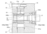
第一実施形態ベーン型回転装置としてベーンモータに適用した場合について、図1〜図6を参照して説明する。本実施形態のベーンモータは、双方向に回転出力が可能なモータである。ベーンモータは、図1〜図4に示すように、カムリング11と、ロータ12と、複数のベーン13と、付勢ばね14と、第一サイドプレート15と、第二サイドプレート16と、出力軸17とを備えて構成される。
<First embodiment>
(Vane motor configuration)
A case where the first embodiment is applied to a vane motor as a vane type rotating device will be described with reference to FIGS. The vane motor of this embodiment is a motor capable of rotating output in both directions. As shown in FIGS. 1 to 4, the vane motor includes a
カムリング11は、図3に示すように、リング状(環状)に形成されており、内周面11aがカム形状に形成されている。以下、カムリング11の内周面11aを内周カム面11aと称する。本実施形態においては、カムリング11の内周カム面11aは、四角形のような形状に形成されており、カムリフト量が大きな位相が4箇所存在する形状である。このカムリング11は、図1および図2に示すように、軸方向において、第一サイドプレート15と第二サイドプレート16によって挟まれた状態で、ボルト21により一体的に固定されている。
As shown in FIG. 3, the
ロータ12は、リング状に形成されており、カムリング11の内周側に回転可能に収容されている。従って、カムリング11の内周カム面11aとロータ12の外周面と間には、位相に応じて異なる径方向隙間が形成されている。このロータ12には、放射方向に延びるように且つ外周面に開口するように複数の案内スリット状溝12aが、周方向に等間隔に形成されている。
The
ロータ12のそれぞれの案内スリット状溝12a内には、ベーン13が放射方向に摺動可能に収容されている。それぞれのベーン13は、ロータ12の外周面に対して放射方向に進退自在に設けられている。これらのベーン13の先端がカムリング11の内周カム面11aに当接することにより、カムリング11の内周カム面11aとロータ12の外周面との径方向隙間が周方向に複数の分割室23に区画される。つまり、それぞれの分割室23の容積は、ロータ12の回転により変化する。このロータ12の内周面には、内歯スプラインが形成されている。このロータ12の内歯スプラインは、出力軸17の外歯スプラインに噛合し、ロータ12の回転動力を出力軸17に伝達可能な構成となっている。
A
さらに、ロータ12のそれぞれの案内スリット状溝12aの溝底には、付勢ばね14が設けられている。付勢ばね14の一端は、案内スリット状溝12aの溝底に取り付けられ、その他端は、ベーン13の背面(径方向内側面)に取り付けられている。つまり、付勢ばね14は、ベーン13に対して径方向外側への付勢力を付与している。また、ロータ12は、第一サイドプレート15と第二サイドプレート16により軸方向に挟まれた状態で、相対回転可能に配置されている。
Further, an urging
第一サイドプレート15のうちカムリング11側の軸方向端面には、第一ポート151aおよび第二ポート151bが、周方向に交互に4箇所ずつ開口形成されている。第一ポート151aおよび第二ポート151bは、カムリング11の内周カム面11aとロータ12の外周面との径方向隙間に対して開口している。各第一ポート151aおよび各第二ポート151bは、図3に示すように、カムリング11の内周カム面11aにおいて、カムリフト量が最大となる位相とカムリフト量が最小となる位相との周方向間に形成されている。そして、各第一ポート151aと各第二ポート151bは、内周カム面11aのカムリフト量が最大となる位相に対して、図3の正面視において、右回り寄りと左回り寄りのそれぞれに形成されている。
On the end surface in the axial direction of the
さらに、第一サイドプレート15には、第一ポート151aに連通するとともに、図示しない流体供給装置および流体排出装置の一方に接続可能な第一給排連通路152aが形成されている。また、第一サイドプレート15には、第二ポート151bに連通するとともに、図示しない流体供給装置および流体排出装置の他方に接続可能な第二給排連通路152bが形成されている。つまり、第一ポート151aは、高圧の流体を供給する流体供給装置が第一給排連通路152aに接続されている場合には、カムリング11の内周カム面11aとロータ12の外周面との間の径方向隙間の分割室23に対して高圧の流体を供給する流体供給ポートとして機能する。このとき、第二ポート151bは、低圧の流体を排出する流体排出装置が第二給排連通路152bに接続されるため、カムリング11の内周カム面11aとロータ12の外周面との間の径方向隙間の分割室23から低圧の流体を排出する流体排出ポートとして機能する。一方、第二給排連通路152bが流体供給装置に接続され、第一給排連通路152aが流体排出装置に接続されている場合には、第二ポート151bが流体供給ポートとして機能し、第一ポート151aが流体排出ポートとして機能する。
Further, the
この第一サイドプレート15のうちカムリング11側の軸方向端面には、さらに、各ベーン13の背圧を発生させるための背圧用流体を供給する第一背圧ポート153a、第二背圧ポート153bおよび第三背圧ポート153cが形成されている。つまり、第一〜第三背圧ポート153a〜153cは、ロータ12の案内スリット状溝12aの溝底の径方向位置に開口形成されている。そして、第一背圧ポート153aは、図3および図4に示すように、第一ポート151aの周方向幅のほぼ中央と同位相に開口形成されている。第二背圧ポート153bは、第一ポート151aと第二ポート151bとの周方向間の位相に開口形成されている。第三背圧ポート153cは、第二ポート151bの周方向幅のほぼ中央と同位相に開口形成されている。つまり、第一背圧ポート153aの周方向の隣り、および、第三背圧ポート153cの周方向の隣りには、第二背圧ポート153bが形成されている。
A first
また、第一サイドプレート15のうちカムリング11側の軸方向端面には、第一背圧ポート153aと隣接する第二背圧ポート153bとの間を絞りにより連通する第一絞り連通路154aが形成されている。また、第一サイドプレート15のうちカムリング11側の軸方向端面には、第三背圧ポート153cと隣接する第二背圧ポート153bとの間を絞りにより連通する第二絞り連通路154bが形成されている。従って、第一〜第三背圧ポート153a〜153cと第一,第二絞り連通路154a,154bとにより、周方向全周に亘って連通している。
In addition, a first
そして、第一背圧ポート153aは、第一給排連通路152aに連通され、第三背圧ポート153cは、第二給排連通路152bに連通されている。つまり、第一給排連通路152aが高圧の流体を供給する流体供給装置に接続され、第二給排連通路152bが低圧の流体を排出する流体排出装置に接続されている場合には、第一背圧ポート153aに高圧の流体が供給され、第三背圧ポート153cから低圧の流体が排出される。そして、第一背圧ポート153aと第三背圧ポート153cとの間においては、第一絞り連通路154a、第二背圧ポート153bおよび第二絞り連通路154bの順に、流体の圧力が低下しながら流体が流れる。
The first
一方、第二給排連通路152bが高圧の流体を供給する流体供給装置に接続され、第一給排連通路152aが低圧の流体を排出する流体排出装置に接続されている場合には、第三背圧ポート153cに高圧の流体が供給され、第一背圧ポート153aから低圧の流体が排出される。そして、第三背圧ポート153cと第一背圧ポート153aとの間においては、第二絞り連通路154b、第二背圧ポート153bおよび第一絞り連通路154aの順に、流体の圧力が低下しながら流体が流れる。
On the other hand, when the second supply /
また、第二サイドプレート16のうちカムリング11側の軸方向端面には、第一ポート161aおよび第二ポート161bが、第一サイドプレート15の第一ポート151aおよび第二ポート151bに対向する位置に同じ大きさで形成されている。さらに、第二サイドプレート16のうちカムリング11側の軸方向端面には、第一背圧ポート163a、第二背圧ポート163b、第三背圧ポート163c、第一絞り連通路164aおよび第二絞り連通路164bが、第一サイドプレート15の第一背圧ポート153a、第二背圧ポート153b、第三背圧ポート153c、第一絞り連通路154aおよび第二絞り連通路154bのそれぞれに対向する位置に同じ大きさで形成されている。
Further, the
(ベーンモータの動作)
次に、上記したベーンモータの動作について図5および図6を参照して説明する。ここで、説明を容易にするために、図5および図6に示すベーン13について、位相に応じて説明する場合には、13a,13b,13c,13d,13eとして説明する。まずは、図5を参照して、ロータ12がカムリング11に対して図5の左回りに回転する場合について説明する。この場合には、第一給排連通路152aが高圧の流体を供給する流体供給装置に接続され、第二給排連通路152bが低圧の流体を排出する流体排出装置に接続される。
(Vane motor operation)
Next, the operation of the vane motor will be described with reference to FIGS. Here, for ease of explanation, the
そうすると、第一ポート151aが流体供給ポートとして機能し、高圧の流体を分割室23に供給する。そうすると、第一ポート151aの位相範囲に位置するベーン13bは、当該ベーン13bにより区画される分割室23の容積が拡大する方向、すなわち図5の左回りに回転する。さらにベーン13が左回りに回転すると、ベーン13により区画される分割室23は、第二ポート151bが形成されている位相範囲まで移動する。そうすると、当該分割室23に収容されていた流体は、第二ポート151bから排出される。このようにして、ロータ12に回転動力が発生する。このロータ12の回転動力は、出力軸17に伝達され、出力軸17を回転させる。
Then, the
このときの各ベーン13の背圧について詳細に検討する。第一ポート151aの位相範囲のほぼ中央に位置するベーン13bの背圧は、以下のようになる。ここで、当該ベーン13bは、隣接する二つの分割室23が第一ポート151aから流体を供給されている場合の当該二つの分割室23を区画するベーン13bである。当該ベーン13bを収容する案内スリット状溝12aの溝底は、第一背圧ポート153aの開口する位相に位置する。つまり、当該ベーン13bに背圧を発生させるための背圧用流体の圧力は、流体供給装置が供給する高圧の流体の圧力となる。従って、当該ベーン13bの背圧は、流体供給装置が供給する高圧の流体の圧力に、付勢ばね14の付勢力を加算したものとなる。ここで、付勢ばね14による付勢力は、流体の圧力に比べて十分に小さいものである。従って、当該ベーン13bの背圧は、流体供給装置が供給する高圧の流体の圧力に対して僅かに大きな圧力となる。
The back pressure of each
第二ポート151bの位相範囲のほぼ中央に位置するベーン13dの背圧は、以下のようになる。ここで、当該ベーン13dは、隣接する二つの分割室23が第二ポート151bへ流体を排出している場合の当該二つの分割室23を区画するベーン13dである。当該ベーン13dを収容する案内スリット状溝12aの溝底は、第三背圧ポート153cの開口する位相に位置する。つまり、当該ベーン13dに背圧を発生させるための背圧用流体の圧力は、流体排出装置が排出する低圧(例えば大気圧)の流体の圧力となる。従って、当該ベーン13dの背圧は、流体排出装置が排出する低圧の流体の圧力に、付勢ばね14の付勢力を加算したものとなる。ここで、付勢ばね14による付勢力は、流体の圧力に比べて十分に小さいものである。従って、当該ベーン13dの背圧は、流体排出装置が排出する低圧の流体の圧力に対して僅かに大きな圧力となる。
The back pressure of the
第一ポート151aと第二ポート151bの位相範囲の周方向間に位置するベーン13a,13c,13eの背圧は、以下のようになる。ここで、当該ベーン13a,13c,13eは、隣接する一方の分割室23が第一ポート151aから流体を供給され、隣接する他方の分割室23が第二ポート151bに流体を排出している場合の当該二つの分割室23を区画するベーン13a,13c,13eである。当該ベーン13a,13c,13eを収容する案内スリット状溝12aの溝底は、第二背圧ポート153bの開口する位相に位置する。ここで、第二背圧ポート153bは、第一背圧ポート153aとの間に第一絞り連通路154aを介在し、第三背圧ポート153cとの間に第二絞り連通路154bを介在している。従って、第二背圧ポート153bにおける流体の圧力は、第一背圧ポート153aに流体供給装置から供給される高圧の流体の圧力と、第三背圧ポート153cから流体排出装置へ排出する低圧の流体の圧力との中間圧力となる。従って、当該ベーン13a,13c,13eの背圧は、第二背圧ポート153bにおける流体の圧力に、付勢ばね14の付勢力を加算したものとなる。ここで、付勢ばね14による付勢力は、流体の圧力に比べて十分に小さいものである。従って、当該ベーン13dの背圧は、第二背圧ポート153bにおける流体の圧力に対して僅かに大きな圧力となる。
The back pressure of the
このように、ベーン13が第一ポート151aの位相範囲から第二ポート151bの位相範囲まで移動する際に、ベーン13の先端側が分割室23における流体から受ける押し戻し力は、徐々に低下していく。そして、図5の各ベーン13の白抜き矢印の長さにて示すように、ベーン13の背圧も同様に、ベーン13が第一ポート151aの位相範囲から第二ポート151bの位相範囲まで移動する際に、徐々に低下していく。ただし、ベーン13の背圧は、ベーン13の先端側が受ける押し戻し力よりも僅かに大きい。
Thus, when the
また、ベーン13が、第二ポート151bの位相範囲から第一ポート151aの位相範囲まで移動する際には、ベーン13の先端側が分割室23における流体から受ける押し戻し力は、徐々に高くなっていく。そして、図5の各ベーン13の白抜き矢印の長さにて示すように、ベーン13の背圧も同様に、ベーン13が第二ポート151bの位相範囲から第一ポート151aの位相範囲まで移動する際に、徐々に高くなっていく。ただし、ベーン13の背圧は、ベーン13の先端側が受ける押し戻し力よりも僅かに大きい。従って、ベーン13がどの位相に位置する場合であっても、ベーン13の先端がカムリング11の内周カム面11aに押しつける力は、ほぼ一定とすることができる。つまり、ベーン13の先端とカムリング11の内周カム面11aとの摩擦力は、ほぼ一定となる。
Further, when the
さらに、ベーン13の先端側が受ける径方向内側へ押し戻される力より、各ベーン13の背圧の方が僅かに高い。従って、ベーン13の先端は、カムリング11の内周カム面11aに確実に当接した状態を維持できる。つまり、ベーン13の先端とカムリング11の内周カム面11aとの摩擦力が、ゼロよりも大きな値でほぼ一定となる。
Furthermore, the back pressure of each
次に、図6を参照して、ロータ12がカムリング11に対して図6の右回りに回転する場合について説明する。この場合には、第二給排連通路152bが高圧の流体を供給する流体供給装置に接続され、第一給排連通路152aが低圧の流体を排出する流体排出装置に接続される。この場合、上述した図5に示す場合に対して、第一ポート151aと第二ポート151bとが逆になり、第一背圧ポート153aと第三背圧ポート153cとが逆になる関係となる。この場合も、回転方向が逆転するのみで、上記と同様の効果を奏する。
Next, the case where the
<第二実施形態>
次に、第二実施形態のベーン型回転装置としてベーンポンプに適用した場合について、図7を参照して説明する。ここで、ベーンポンプの構成は、上述したベーンモータに対して、流体供給装置が低圧の流体を供給し、流体排出装置が高圧の流体を排出し、出力軸17が回転動力をロータ12に入力する入力軸として機能する点が相違する。その他の構成は、共通する。
<Second embodiment>
Next, the case where it applies to a vane pump as a vane type rotating apparatus of 2nd embodiment is demonstrated with reference to FIG. Here, the configuration of the vane pump is such that the fluid supply device supplies the low-pressure fluid to the vane motor described above, the fluid discharge device discharges the high-pressure fluid, and the
この場合の動作は、以下のとおりである。なお、図7においては、ロータ12が図7の左回りに回転する場合を示している。そして、第一ポート151aが流体供給ポートとして機能し、低圧の流体が分割室23に供給される。そうすると、ロータ12の左回りの回転に伴って、分割室23の容積が小さくなるため、分割室23に収容されている流体の圧力が高くなっていく。そして、高圧の流体が収容されている分割室23が第二ポート151bの位相範囲に到達すると、高圧の流体は第二ポート151bを介して流体排出装置へ排出される。
The operation in this case is as follows. 7 shows a case where the
このときの各ベーン13の背圧について詳細に検討する。第一ポート151aの位相範囲のほぼ中央に位置するベーン13bの背圧は、以下のようになる。ここで、当該ベーン13bは、隣接する二つの分割室23が第一ポート151aから流体を供給されている場合の当該二つの分割室23を区画するベーン13bである。当該ベーン13bを収容する案内スリット状溝12aの溝底は、第一背圧ポート153aの開口する位相に位置する。つまり、当該ベーン13bに背圧を発生させるための背圧用流体の圧力は、流体供給装置が供給する低圧の流体の圧力となる。従って、当該ベーン13bの背圧は、流体供給装置が供給する低圧の流体の圧力に、付勢ばね14の付勢力を加算したものとなる。ここで、付勢ばね14による付勢力は、流体の圧力に比べて十分に小さいものである。従って、当該ベーン13bの背圧は、流体供給装置が供給する低圧の流体の圧力に対して僅かに大きな圧力となる。
The back pressure of each
第二ポート151bの位相範囲のほぼ中央に位置するベーン13dの背圧は、以下のようになる。ここで、当該ベーン13dは、隣接する二つの分割室23が第二ポート151bへ流体を排出している場合の当該二つの分割室23を区画するベーン13dである。当該ベーン13dを収容する案内スリット状溝12aの溝底は、第三背圧ポート153cの開口する位相に位置する。つまり、当該ベーン13dに背圧を発生させるための背圧用流体の圧力は、流体排出装置が排出する高圧の流体の圧力となる。従って、当該ベーン13dの背圧は、流体排出装置が排出する高圧の流体の圧力に、付勢ばね14の付勢力を加算したものとなる。ここで、付勢ばね14による付勢力は、流体の圧力に比べて十分に小さいものである。従って、当該ベーン13dの背圧は、流体排出装置が排出する高圧の流体の圧力に対して僅かに大きな圧力となる。
The back pressure of the
第一ポート151aと第二ポート151bの位相範囲の周方向間に位置するベーン13a,13c,13eの背圧は、以下のようになる。ここで、当該ベーン13a,13c,13eは、隣接する一方の分割室23が第一ポート151aから流体を供給され、隣接する他方の分割室23が第二ポート151bに流体を排出している場合の当該二つの分割室23を区画するベーン13a,13c,13eである。当該ベーン13a,13c,13eを収容する案内スリット状溝12aの溝底は、第二背圧ポート153bの開口する位相に位置する。ここで、第二背圧ポート153bは、第一背圧ポート153aとの間に第一絞り連通路154aを介在し、第三背圧ポート153cとの間に第二絞り連通路154bを介在している。従って、第二背圧ポート153bにおける流体の圧力は、第一背圧ポート153aに流体供給装置から供給される低圧の流体の圧力と、第三背圧ポート153cから流体排出装置へ排出する高圧の流体の圧力との中間圧力となる。従って、当該ベーン13a,13c,13eの背圧は、第二背圧ポート153bにおける流体の圧力に、付勢ばね14の付勢力を加算したものとなる。ここで、付勢ばね14による付勢力は、流体の圧力に比べて十分に小さいものである。従って、当該ベーン13dの背圧は、第二背圧ポート153bにおける流体の圧力に対して僅かに大きな圧力となる。
The back pressure of the
このように、ベーン13が第一ポート151aの位相範囲から第二ポート151bの位相範囲まで移動する際に、ベーン13の先端側が分割室23における流体から受ける押し戻し力は、徐々に高くなっていく。そして、図7の各ベーン13の白抜き矢印の長さにて示すように、ベーン13の背圧も同様に、ベーン13が第一ポート151aの位相範囲から第二ポート151bの位相範囲まで移動する際に、徐々に高くなっていく。ただし、ベーン13の背圧は、ベーン13の先端側が受ける押し戻し力よりも僅かに大きい。
Thus, when the
また、ベーン13が、第二ポート151bの位相範囲から第一ポート151aの位相範囲まで移動する際には、ベーン13の先端側が分割室23における流体から受ける押し戻し力は、徐々に低下していく。そして、図7の各ベーン13の白抜き矢印の長さにて示すように、ベーン13の背圧も同様に、ベーン13が第二ポート151bの位相範囲から第一ポート151aの位相範囲まで移動する際に、徐々に低下していく。ただし、ベーン13の背圧は、ベーン13の先端側が受ける押し戻し力よりも僅かに大きい。従って、ベーン13がどの位相に位置する場合であっても、ベーン13の先端がカムリング11の内周カム面11aに押しつける力は、ほぼ一定とすることができる。つまり、ベーン13の先端とカムリング11の内周カム面11aとの摩擦力は、ほぼ一定となる。
Further, when the
さらに、ベーン13の先端側が受ける径方向内側へ押し戻される力より、各ベーン13の背圧の方が僅かに高い。従って、ベーン13の先端は、カムリング11の内周カム面11aに確実に当接した状態を維持できる。つまり、ベーン13の先端とカムリング11の内周カム面11aとの摩擦力が、ゼロよりも大きな値でほぼ一定となる。
Furthermore, the back pressure of each
また、ロータ12が図7の右回りに回転する場合には、第二給排連通路152bが低圧の流体を供給する流体供給装置に接続され、第一給排連通路152aが高圧の流体を排出する流体排出装置に接続される。この場合、上述した図7に示す場合に対して、第一ポート151aと第二ポート151bとが逆になり、第一背圧ポート153aと第三背圧ポート153cとが逆になる関係となる。この場合も、回転方向が逆転するのみで、上記と同様の効果を奏する。
When the
<その他>
上記実施形態において、付勢ばね14を設けることにより、ベーン13が受ける押し戻し力より、ベーン13の背圧が僅かに大きくなるようにした。この構成の他に、第一背圧ポート153aと第一給排連通路152aとの間、および、第三背圧ポート153cと第二給排連通路152bとの間に、絞り連通路をそれぞれ設ける構成としてもよい。この場合にも、同様に、ベーン13が受ける押し戻し力より、ベーン13の背圧が僅かに大きくなるようにできる。また、上記実施形態におけるベーン型回転装置は、双方向に回転可能な構成として説明したが、一方向に回転可能な装置としても適用できる。
<Others>
In the above embodiment, by providing the urging
11:カムリング、 11a:内周カム面
12:ロータ、 12a:案内スリット状溝、 13,13a〜13e:ベーン
15:第一サイドプレート、 16:第二サイドプレート、 17:出力軸
21:ボルト、 23:分割室
151a:第一ポート、 151b:第二ポート
152a:第一給排連通路、 152b:第二給排連通路
153a:第一背圧ポート、 153b:第二背圧ポート、 153c:第三背圧ポート
154a:第一絞り連通路、 154b:第二絞り連通路
161a:第一ポート、 161b:第二ポート
163a:第一背圧ポート、 163b:第二背圧ポート、 163c:第三背圧ポート
164a:第一絞り連通路、 164b:第二絞り連通路
11: Cam ring, 11a: Inner peripheral cam surface 12: Rotor, 12a: Guide slit groove, 13, 13a to 13e: Vane 15: First side plate, 16: Second side plate, 17: Output shaft 21: Bolt, 23:
Claims (4)
前記カムリングの内周側に回転可能に収容され、放射方向に延びるように且つ外周面に開口するように複数の案内スリット状溝が形成されたロータと、
それぞれの前記案内スリット状溝内に摺動可能に収容され、前記ロータの外周面に対して放射方向に進退自在に設けられ、前記カムリングの内周面に当接することにより前記カムリングと前記ロータとの径方向隙間を周方向に複数の分割室に区画する複数のベーンと、
前記カムリングと前記ロータとの径方向隙間に流体を供給する流体供給ポートと、
前記流体供給ポートに対して周方向に異なる位置に形成され、前記カムリングと前記ロータとの径方向隙間の流体を排出する流体排出ポートと、
隣接する二つの前記分割室が前記流体供給ポートから流体を供給されている場合の当該二つの前記分割室を区画する供給側の前記ベーンの背圧と、隣接する二つの前記分割室が前記流体排出ポートへ流体を排出している場合の当該二つの前記分割室を区画する排出側の前記ベーンの背圧と、隣接する一方の前記分割室が前記流体供給ポートから流体を供給され他方の前記分割室が前記流体排出ポートに流体を排出している場合の当該二つの前記分割室を区画する中間の前記ベーンの背圧とをそれぞれ異なる圧力とするベーン背圧調整手段と、
を備えることを特徴とするベーン型回転装置。 A cam ring having an inner peripheral surface formed in a cam shape;
A rotor that is rotatably accommodated on the inner peripheral side of the cam ring, and that has a plurality of guide slit-shaped grooves formed to extend in the radial direction and open to the outer peripheral surface;
The cam ring and the rotor are slidably accommodated in the respective guide slit-shaped grooves, are provided so as to be movable forward and backward in a radial direction with respect to the outer peripheral surface of the rotor, and come into contact with the inner peripheral surface of the cam ring. A plurality of vanes that divide a radial clearance of
A fluid supply port for supplying fluid to a radial gap between the cam ring and the rotor;
A fluid discharge port that is formed at different positions in the circumferential direction with respect to the fluid supply port and discharges fluid in a radial gap between the cam ring and the rotor;
The back pressure of the vane on the supply side that divides the two divided chambers when the two adjacent divided chambers are supplied with fluid from the fluid supply port, and the two adjacent divided chambers are the fluid. When the fluid is discharged to the discharge port, the back pressure of the vane on the discharge side that divides the two divided chambers, and one of the adjacent divided chambers is supplied with fluid from the fluid supply port, and the other A vane back pressure adjusting means for setting different back pressures of the intermediate vanes dividing the two divided chambers when the divided chambers are discharging fluid to the fluid discharge port;
A vane-type rotating device comprising:
前記背圧調整手段は、
それぞれの前記案内スリット状溝の溝底に前記ベーンの背圧を発生させるための背圧用流体を供給する複数の背圧ポートと、
隣接する前記背圧ポートの間を絞りにより連通する絞り連通路と、
を備え、
隣接する前記背圧ポートの一方に供給される背圧用流体は、前記絞り連通路を介して隣接する前記背圧ポートの他方に供給されることを特徴とするベーン型回転装置。 In claim 1,
The back pressure adjusting means includes
A plurality of back pressure ports for supplying back pressure fluid for generating back pressure of the vane at the groove bottom of each guide slit groove;
A throttle communication passage communicating between the back pressure ports adjacent to each other by a throttle;
With
The vane type rotating device, wherein the back pressure fluid supplied to one of the adjacent back pressure ports is supplied to the other of the adjacent back pressure ports via the throttle communication path.
前記背圧ポートは、前記供給側のベーン、前記排出側のベーンおよび前記中間のベーンが収容されたそれぞれの前記案内スリット状溝の溝底に前記背圧用流体をそれぞれ供給する供給側、排出側、中間の背圧ポートを備え、
前記絞り連通路は、前記供給側の背圧ポートと前記中間の背圧ポートとを絞りにより連通する供給側絞り連通路と、前記中間の背圧ポートと前記排出側の背圧ポートとを絞りにより連通する排出側絞り連通路とを備え、
前記供給側の背圧ポートは、前記流体供給ポートに接続され、
前記排出側の背圧ポートは、前記流体排出ポートに接続され、
前記中間の背圧ポートにおける前記背圧用流体は、前記供給側の背圧ポートおよび前記供給側絞り連通路を介して供給され、前記排出側の背圧ポートおよび前記排出側絞り連通路を介して排出されることを特徴とするベーン型回転装置。 In claim 2,
The back pressure port includes a supply side and a discharge side for supplying the back pressure fluid to the groove bottoms of the guide slit grooves in which the supply side vane, the discharge side vane, and the intermediate vane are accommodated, respectively. With an intermediate back pressure port,
The throttle communication passage restricts the supply-side throttle communication passage that connects the supply-side back pressure port and the intermediate back-pressure port by the throttle, and the intermediate back-pressure port and the discharge-side back pressure port. And a discharge side throttle communication passage communicating with
The back pressure port on the supply side is connected to the fluid supply port;
The back pressure port on the discharge side is connected to the fluid discharge port;
The back-pressure fluid in the intermediate back-pressure port is supplied via the supply-side back pressure port and the supply-side throttle communication path, and is supplied via the discharge-side back pressure port and the discharge-side throttle communication path. A vane type rotating device characterized by being discharged.
前記背圧調整手段は、前記供給側の背圧ポートにおける前記背圧用流体の圧力を、前記流体供給ポートにおける流体の圧力より高くし、且つ、前記排出側の背圧ポートにおける前記背圧用流体の圧力を、前記流体排出ポートにおける流体の圧力より高くすることを特徴とするベーン型回転装置。 In claim 3,
The back pressure adjusting means makes the pressure of the back pressure fluid in the back pressure port on the supply side higher than the pressure of the fluid in the fluid supply port, and the back pressure fluid in the back pressure port on the discharge side. A vane type rotating device characterized in that the pressure is higher than the pressure of the fluid in the fluid discharge port.
Priority Applications (1)
| Application Number | Priority Date | Filing Date | Title |
|---|---|---|---|
| JP2010137858A JP2012002136A (en) | 2010-06-17 | 2010-06-17 | Vane type rotating device |
Applications Claiming Priority (1)
| Application Number | Priority Date | Filing Date | Title |
|---|---|---|---|
| JP2010137858A JP2012002136A (en) | 2010-06-17 | 2010-06-17 | Vane type rotating device |
Publications (1)
| Publication Number | Publication Date |
|---|---|
| JP2012002136A true JP2012002136A (en) | 2012-01-05 |
Family
ID=45534397
Family Applications (1)
| Application Number | Title | Priority Date | Filing Date |
|---|---|---|---|
| JP2010137858A Pending JP2012002136A (en) | 2010-06-17 | 2010-06-17 | Vane type rotating device |
Country Status (1)
| Country | Link |
|---|---|
| JP (1) | JP2012002136A (en) |
-
2010
- 2010-06-17 JP JP2010137858A patent/JP2012002136A/en active Pending
Similar Documents
| Publication | Publication Date | Title |
|---|---|---|
| JP2013050067A (en) | Vane pump | |
| JP4215515B2 (en) | Variable displacement pump with rotating cam ring | |
| US9261063B2 (en) | Vehicle oil pump | |
| CN106989012A (en) | Vane pump apparatus | |
| US20140271310A1 (en) | Clubhead Vane Pump With Balanced Vanes | |
| JP2010223110A (en) | Variable displacement vane pump | |
| JP2012002136A (en) | Vane type rotating device | |
| JP2013127249A (en) | Multi-discharge port hydraulic vane pump | |
| JP2014177902A (en) | Vane pump | |
| JPH04265484A (en) | Tandem pump | |
| JP5865631B2 (en) | Vane pump | |
| JP2017514064A (en) | Vane pump with adjustable discharge rate | |
| US9353744B2 (en) | Vane-type hydraulic device having vane formed with engaging groove | |
| CN106968944B (en) | Vane pump device | |
| CN112204258B (en) | Rotational flow device | |
| JPWO2005005837A1 (en) | Vane pump | |
| WO2020090817A1 (en) | Vane pump | |
| US9188111B2 (en) | Displacement assembly for a fluid device | |
| JP6711528B2 (en) | Variable displacement pump | |
| WO2022004204A1 (en) | Axial piston device | |
| JP2010265852A (en) | Vane pump | |
| EP3150851B1 (en) | Improved displacement pump | |
| JP4410528B2 (en) | Variable displacement vane pump | |
| JP2015203385A (en) | Hydraulic control device for vehicle | |
| JP6633837B2 (en) | Vane pump |