JP2011524204A - System and method for delivering energy to tissue - Google Patents
System and method for delivering energy to tissue Download PDFInfo
- Publication number
- JP2011524204A JP2011524204A JP2011513696A JP2011513696A JP2011524204A JP 2011524204 A JP2011524204 A JP 2011524204A JP 2011513696 A JP2011513696 A JP 2011513696A JP 2011513696 A JP2011513696 A JP 2011513696A JP 2011524204 A JP2011524204 A JP 2011524204A
- Authority
- JP
- Japan
- Prior art keywords
- energy source
- energy
- tissue
- transducer
- ablation
- Prior art date
- Legal status (The legal status is an assumption and is not a legal conclusion. Google has not performed a legal analysis and makes no representation as to the accuracy of the status listed.)
- Pending
Links
Images


Classifications
-
- A—HUMAN NECESSITIES
- A61—MEDICAL OR VETERINARY SCIENCE; HYGIENE
- A61B—DIAGNOSIS; SURGERY; IDENTIFICATION
- A61B18/00—Surgical instruments, devices or methods for transferring non-mechanical forms of energy to or from the body
-
- A—HUMAN NECESSITIES
- A61—MEDICAL OR VETERINARY SCIENCE; HYGIENE
- A61B—DIAGNOSIS; SURGERY; IDENTIFICATION
- A61B18/00—Surgical instruments, devices or methods for transferring non-mechanical forms of energy to or from the body
- A61B18/04—Surgical instruments, devices or methods for transferring non-mechanical forms of energy to or from the body by heating
- A61B18/08—Surgical instruments, devices or methods for transferring non-mechanical forms of energy to or from the body by heating by means of electrically-heated probes
-
- A—HUMAN NECESSITIES
- A61—MEDICAL OR VETERINARY SCIENCE; HYGIENE
- A61B—DIAGNOSIS; SURGERY; IDENTIFICATION
- A61B18/00—Surgical instruments, devices or methods for transferring non-mechanical forms of energy to or from the body
- A61B18/04—Surgical instruments, devices or methods for transferring non-mechanical forms of energy to or from the body by heating
- A61B18/12—Surgical instruments, devices or methods for transferring non-mechanical forms of energy to or from the body by heating by passing a current through the tissue to be heated, e.g. high-frequency current
- A61B18/14—Probes or electrodes therefor
- A61B18/1492—Probes or electrodes therefor having a flexible, catheter-like structure, e.g. for heart ablation
-
- A—HUMAN NECESSITIES
- A61—MEDICAL OR VETERINARY SCIENCE; HYGIENE
- A61B—DIAGNOSIS; SURGERY; IDENTIFICATION
- A61B18/00—Surgical instruments, devices or methods for transferring non-mechanical forms of energy to or from the body
- A61B18/18—Surgical instruments, devices or methods for transferring non-mechanical forms of energy to or from the body by applying electromagnetic radiation, e.g. microwaves
- A61B18/1815—Surgical instruments, devices or methods for transferring non-mechanical forms of energy to or from the body by applying electromagnetic radiation, e.g. microwaves using microwaves
-
- A—HUMAN NECESSITIES
- A61—MEDICAL OR VETERINARY SCIENCE; HYGIENE
- A61B—DIAGNOSIS; SURGERY; IDENTIFICATION
- A61B18/00—Surgical instruments, devices or methods for transferring non-mechanical forms of energy to or from the body
- A61B18/18—Surgical instruments, devices or methods for transferring non-mechanical forms of energy to or from the body by applying electromagnetic radiation, e.g. microwaves
- A61B18/20—Surgical instruments, devices or methods for transferring non-mechanical forms of energy to or from the body by applying electromagnetic radiation, e.g. microwaves using laser
- A61B18/22—Surgical instruments, devices or methods for transferring non-mechanical forms of energy to or from the body by applying electromagnetic radiation, e.g. microwaves using laser the beam being directed along or through a flexible conduit, e.g. an optical fibre; Couplings or hand-pieces therefor
- A61B18/24—Surgical instruments, devices or methods for transferring non-mechanical forms of energy to or from the body by applying electromagnetic radiation, e.g. microwaves using laser the beam being directed along or through a flexible conduit, e.g. an optical fibre; Couplings or hand-pieces therefor with a catheter
-
- A—HUMAN NECESSITIES
- A61—MEDICAL OR VETERINARY SCIENCE; HYGIENE
- A61N—ELECTROTHERAPY; MAGNETOTHERAPY; RADIATION THERAPY; ULTRASOUND THERAPY
- A61N7/00—Ultrasound therapy
- A61N7/02—Localised ultrasound hyperthermia
- A61N7/022—Localised ultrasound hyperthermia intracavitary
-
- A—HUMAN NECESSITIES
- A61—MEDICAL OR VETERINARY SCIENCE; HYGIENE
- A61B—DIAGNOSIS; SURGERY; IDENTIFICATION
- A61B18/00—Surgical instruments, devices or methods for transferring non-mechanical forms of energy to or from the body
- A61B18/02—Surgical instruments, devices or methods for transferring non-mechanical forms of energy to or from the body by cooling, e.g. cryogenic techniques
-
- A—HUMAN NECESSITIES
- A61—MEDICAL OR VETERINARY SCIENCE; HYGIENE
- A61B—DIAGNOSIS; SURGERY; IDENTIFICATION
- A61B18/00—Surgical instruments, devices or methods for transferring non-mechanical forms of energy to or from the body
- A61B18/18—Surgical instruments, devices or methods for transferring non-mechanical forms of energy to or from the body by applying electromagnetic radiation, e.g. microwaves
- A61B18/20—Surgical instruments, devices or methods for transferring non-mechanical forms of energy to or from the body by applying electromagnetic radiation, e.g. microwaves using laser
-
- A—HUMAN NECESSITIES
- A61—MEDICAL OR VETERINARY SCIENCE; HYGIENE
- A61B—DIAGNOSIS; SURGERY; IDENTIFICATION
- A61B17/00—Surgical instruments, devices or methods, e.g. tourniquets
- A61B2017/00017—Electrical control of surgical instruments
- A61B2017/00022—Sensing or detecting at the treatment site
- A61B2017/00084—Temperature
-
- A—HUMAN NECESSITIES
- A61—MEDICAL OR VETERINARY SCIENCE; HYGIENE
- A61B—DIAGNOSIS; SURGERY; IDENTIFICATION
- A61B18/00—Surgical instruments, devices or methods for transferring non-mechanical forms of energy to or from the body
- A61B2018/00005—Cooling or heating of the probe or tissue immediately surrounding the probe
- A61B2018/00011—Cooling or heating of the probe or tissue immediately surrounding the probe with fluids
- A61B2018/00029—Cooling or heating of the probe or tissue immediately surrounding the probe with fluids open
-
- A—HUMAN NECESSITIES
- A61—MEDICAL OR VETERINARY SCIENCE; HYGIENE
- A61B—DIAGNOSIS; SURGERY; IDENTIFICATION
- A61B18/00—Surgical instruments, devices or methods for transferring non-mechanical forms of energy to or from the body
- A61B2018/00053—Mechanical features of the instrument of device
- A61B2018/00059—Material properties
- A61B2018/00089—Thermal conductivity
- A61B2018/00095—Thermal conductivity high, i.e. heat conducting
-
- A—HUMAN NECESSITIES
- A61—MEDICAL OR VETERINARY SCIENCE; HYGIENE
- A61B—DIAGNOSIS; SURGERY; IDENTIFICATION
- A61B18/00—Surgical instruments, devices or methods for transferring non-mechanical forms of energy to or from the body
- A61B2018/00315—Surgical instruments, devices or methods for transferring non-mechanical forms of energy to or from the body for treatment of particular body parts
- A61B2018/00345—Vascular system
- A61B2018/00351—Heart
- A61B2018/00357—Endocardium
-
- A—HUMAN NECESSITIES
- A61—MEDICAL OR VETERINARY SCIENCE; HYGIENE
- A61B—DIAGNOSIS; SURGERY; IDENTIFICATION
- A61B18/00—Surgical instruments, devices or methods for transferring non-mechanical forms of energy to or from the body
- A61B2018/00571—Surgical instruments, devices or methods for transferring non-mechanical forms of energy to or from the body for achieving a particular surgical effect
- A61B2018/00577—Ablation
-
- A—HUMAN NECESSITIES
- A61—MEDICAL OR VETERINARY SCIENCE; HYGIENE
- A61B—DIAGNOSIS; SURGERY; IDENTIFICATION
- A61B18/00—Surgical instruments, devices or methods for transferring non-mechanical forms of energy to or from the body
- A61B2018/00636—Sensing and controlling the application of energy
- A61B2018/00696—Controlled or regulated parameters
- A61B2018/00714—Temperature
-
- A—HUMAN NECESSITIES
- A61—MEDICAL OR VETERINARY SCIENCE; HYGIENE
- A61B—DIAGNOSIS; SURGERY; IDENTIFICATION
- A61B18/00—Surgical instruments, devices or methods for transferring non-mechanical forms of energy to or from the body
- A61B18/02—Surgical instruments, devices or methods for transferring non-mechanical forms of energy to or from the body by cooling, e.g. cryogenic techniques
- A61B2018/0212—Surgical instruments, devices or methods for transferring non-mechanical forms of energy to or from the body by cooling, e.g. cryogenic techniques using an instrument inserted into a body lumen, e.g. catheter
-
- A—HUMAN NECESSITIES
- A61—MEDICAL OR VETERINARY SCIENCE; HYGIENE
- A61B—DIAGNOSIS; SURGERY; IDENTIFICATION
- A61B18/00—Surgical instruments, devices or methods for transferring non-mechanical forms of energy to or from the body
- A61B18/18—Surgical instruments, devices or methods for transferring non-mechanical forms of energy to or from the body by applying electromagnetic radiation, e.g. microwaves
- A61B18/1815—Surgical instruments, devices or methods for transferring non-mechanical forms of energy to or from the body by applying electromagnetic radiation, e.g. microwaves using microwaves
- A61B2018/1861—Surgical instruments, devices or methods for transferring non-mechanical forms of energy to or from the body by applying electromagnetic radiation, e.g. microwaves using microwaves with an instrument inserted into a body lumen or cavity, e.g. a catheter
-
- A—HUMAN NECESSITIES
- A61—MEDICAL OR VETERINARY SCIENCE; HYGIENE
- A61B—DIAGNOSIS; SURGERY; IDENTIFICATION
- A61B90/00—Instruments, implements or accessories specially adapted for surgery or diagnosis and not covered by any of the groups A61B1/00 - A61B50/00, e.g. for luxation treatment or for protecting wound edges
- A61B90/06—Measuring instruments not otherwise provided for
- A61B2090/061—Measuring instruments not otherwise provided for for measuring dimensions, e.g. length
-
- A—HUMAN NECESSITIES
- A61—MEDICAL OR VETERINARY SCIENCE; HYGIENE
- A61N—ELECTROTHERAPY; MAGNETOTHERAPY; RADIATION THERAPY; ULTRASOUND THERAPY
- A61N7/00—Ultrasound therapy
- A61N2007/0073—Ultrasound therapy using multiple frequencies
Landscapes
- Health & Medical Sciences (AREA)
- Life Sciences & Earth Sciences (AREA)
- Surgery (AREA)
- Engineering & Computer Science (AREA)
- Veterinary Medicine (AREA)
- Animal Behavior & Ethology (AREA)
- Nuclear Medicine, Radiotherapy & Molecular Imaging (AREA)
- Public Health (AREA)
- Biomedical Technology (AREA)
- General Health & Medical Sciences (AREA)
- Heart & Thoracic Surgery (AREA)
- Molecular Biology (AREA)
- Medical Informatics (AREA)
- Otolaryngology (AREA)
- Physics & Mathematics (AREA)
- Electromagnetism (AREA)
- Plasma & Fusion (AREA)
- Radiology & Medical Imaging (AREA)
- Cardiology (AREA)
- Optics & Photonics (AREA)
- Surgical Instruments (AREA)
- Laser Surgery Devices (AREA)
Abstract
患者を治療する方法および装置は、心房細動を治療する切除デバイスを含む。デバイスは、近位端と、遠位端と、ハウジングの遠位端に隣接するエネルギー源とを有するハウジングを含む。エネルギー源は、活動部分と不活動部分とを有する。活動部分は、エネルギー源に電力が通されたとき、組織にエネルギーを送達するように適合される。これは、組織に部分的または完全な切除帯を作り、切除帯は異常な電気的活動をブロックし、それによって、患者の心房細動を減少させるかまたは除去する。不活動部分は、エネルギー源に電力が通されたとき、エネルギーを放出しないかまたは実質的にエネルギーを放出しない。A method and apparatus for treating a patient includes an ablation device for treating atrial fibrillation. The device includes a housing having a proximal end, a distal end, and an energy source adjacent to the distal end of the housing. The energy source has an active part and an inactive part. The active portion is adapted to deliver energy to the tissue when power is passed to the energy source. This creates a partial or complete ablation zone in the tissue, which blocks abnormal electrical activity, thereby reducing or eliminating the patient's atrial fibrillation. The inactive portion does not release or substantially does not release energy when power is passed to the energy source.
Description
(発明の背景)
(発明の分野)
本発明は、概して医療デバイスおよび方法に関し、より具体的には、人間または他の動物を治療するために用いられるデバイスによって作られる切除帯を制御する改良されたデバイスおよび方法に関する。本デバイスは、心房細動を治療するために用いられ得る。
(Background of the Invention)
(Field of Invention)
The present invention relates generally to medical devices and methods, and more specifically to improved devices and methods for controlling ablation zones created by devices used to treat humans or other animals. The device can be used to treat atrial fibrillation.
心房細動(AF)の状態は、心筋の正常な同期の動き(「正常洞調律」)から調子が外れる、心臓の左心房の異常な(通常非常に速い)拍動を特徴とする。正常洞調律において、電気的インパルスは、右心房にある洞房結節(「SA結節(node)」)において生じる。心房の心筋の異常な拍動は、細動として公知であり、肺静脈(「PV」)において代わりに生じる電気的インパルスによって引き起こされる(非特許文献1)。 The state of atrial fibrillation (AF) is characterized by an abnormal (usually very fast) beat of the left atrium of the heart that is out of tune with the normal synchronized movement of the myocardium (“normal sinus rhythm”). In normal sinus rhythm, electrical impulses occur in the sinoatrial node in the right atrium (the “SA node”). Abnormal beats of the atrial myocardium, known as fibrillation, are caused by electrical impulses that occur instead in the pulmonary veins ("PV") (1).
様々な成功の度合いを有する、この状態に対する薬理学的治療がある。さらに、PVから左心房(「LA」)への迷入の電気的経路を除去することを意図する、Cox−Maze III Procedureなどの外科手術的介入がある(非特許文献2)(非特許文献3)(非特許文献4)。この処置は99%有効であることが示される(非特許文献5)が、特別の外科手術的スキルを必要とし、時間がかかる。 There are pharmacological treatments for this condition with varying degrees of success. In addition, there are surgical interventions such as Cox-Maze III Procedure that are intended to eliminate the electrical path of entry from PV to the left atrium ("LA") (Non-patent Document 3). (Non-Patent Document 4). This procedure has been shown to be 99% effective (5) but requires special surgical skills and is time consuming.
より非侵襲的で経皮カテーテルベースのアプローチのためにCox−Maze処置をまねる相当な努力がなされてきた。異常な信号がPVにおいて生じる迷入の焦点を囲む組織を切除する(または殺す)ある形態のエネルギーを用いることを伴う侵襲性の少ない治療が開発されてきた。最も一般的な方法論は、無線周波数(「RF」)電気的エネルギーを用いて、筋肉組織を加熱し、それによって筋肉組織を切除することである。迷入の電気的インパルスは次いで、PVから心房に進むことが妨げられ(心臓組織内の伝導ブロックを達成し)、従って心房筋の細動を回避する。マイクロ波、レーザ、および超音波などの他のエネルギー源が、伝導ブロックを達成するために利用されてきた。さらに凍結切除、エタノールの投与などの技術もまた用いられてきた。 Considerable efforts have been made to mimic the Cox-Maze procedure for a more non-invasive and percutaneous catheter-based approach. Less invasive treatments have been developed that involve using some form of energy to ablate (or kill) the tissue surrounding the invading focus where abnormal signals occur in PV. The most common methodology is to use radio frequency (“RF”) electrical energy to heat muscle tissue and thereby ablate muscle tissue. Intrusive electrical impulses are then prevented from proceeding from the PV to the atrium (achieving a conduction block in the heart tissue), thus avoiding atrial muscle fibrillation. Other energy sources such as microwaves, lasers, and ultrasound have been utilized to achieve the conduction block. In addition, techniques such as cryoablation and ethanol administration have also been used.
無線周波数(RF)エネルギーを用いるAFの治療のためにカテーテルベースのシステムを開発する相当な努力がなされてきた。そのような方法の1つは、Haissaguerreらへの特許文献1に説明されている。このアプローチにおいて、カテーテルは、先端が遠位および近位の電極から作られる。カテーテルは、J形状に曲げられ得、肺静脈内に位置を決められ得る。PVの内壁の組織は、迷入の心臓活動源を殺す試みにおいて切除される。他のRFベースのカテーテルは、Schwartzらへの特許文献2、Maguireらへの特許文献3、Leshへの特許文献4、およびStewartらへの特許文献5に説明される。 Considerable efforts have been made to develop catheter-based systems for the treatment of AF using radio frequency (RF) energy. One such method is described in US Pat. In this approach, the catheter is made from electrodes with distal and proximal tips. The catheter can be bent into a J shape and positioned within the pulmonary vein. The tissue on the inner wall of the PV is excised in an attempt to kill the source of the invading heart activity. Other RF-based catheters are described in U.S. Pat. No. 6,057,028 to Schwartz et al., U.S. Pat.
切除に用いられる別の供給源は、マイクロ波である。そのようなデバイスの1つは、Dr.Mark Levinsonによる非特許文献6およびMaessenらの非特許文献7に説明される。この術中デバイスは、心房組織を切除する能力を有する可鍛性アンテナを有するプローブから成る。他のマイクロ波ベースのカテーテルは、Walinskyへの特許文献6、Langbergへの特許文献7、Grundyらへの特許文献8、およびStemらへの特許文献9に説明される。
Another source used for ablation is microwaves. One such device is Dr. Non-Patent Document 6 by Mark Levinson and Non-Patent
別のカテーテルベースの方法は、心房の組織が−60℃より低い温度で凍結される冷凍技術を利用する。これは、結果として、PVの近くの組織を殺すことになり、それによって、AFを引き起こす迷入信号のための通路を除去する(非特許文献8)。冷凍ベースの技術は、部分的Mase処置の一部である(非特許文献9および非特許文献10)。より最近では、Dr.Coxおよび彼のグループ(非特許文献11および非特許文献12)は、冷凍プローブ(冷凍Maze)を用い、Cox−Maze III処置の本質的要素を二重にした。他の冷凍ベースのデバイスは、Lafintaineへの特許文献10および特許文献11、ならびにCoxらへの特許文献12に説明される。 Another catheter-based method utilizes a freezing technique in which atrial tissue is frozen at temperatures below -60 ° C. This results in killing the tissue near the PV, thereby eliminating the path for the intrusion signal that causes AF (Non-Patent Document 8). The refrigeration-based technology is part of the partial case treatment (Non-patent document 9 and Non-patent document 10). More recently Dr. Cox and his group (11 and 12) used a cryoprobe (frozen Maze) to duplicate the essential elements of Cox-Maze III treatment. Other refrigeration based devices are described in US Pat.
AF治療に対するより最近のアプローチは、超音波エネルギーを用いることを伴う。肺静脈を囲む領域の標的組織は、1つ以上の超音波トランスデューサによって放出される超音波エネルギーによって加熱される。そのようなアプローチの1つは、Leshらによって特許文献13に説明される。ここでカテーテル遠位先端部分は、超音波要素を含むバルーンが装備される。バルーンは、肺静脈にカテーテルの先端を固定する(secure)固定(anchoring)手段として働く。カテーテルのバルーン部分は選択された肺静脈に位置を決められ、バルーンは、超音波エネルギーに透過性である流体で膨張させられる。トランスデューサは、超音波エネルギーを放出し、その超音波エネルギーは、肺静脈におけるまたは肺静脈の近くの標的組織に伝わり、その標的組織を切除する。意図された療法は、肺静脈の周りの電気的伝導経路を破壊し、それによって正常洞調律を回復する。療法は、必要に応じて個々の肺静脈の周りに多数の外傷を作ることを伴う。発明者らは、エネルギー放出器および固定機構の様々な構成を説明する。 A more recent approach to AF treatment involves using ultrasound energy. The target tissue in the area surrounding the pulmonary veins is heated by the ultrasonic energy emitted by one or more ultrasonic transducers. One such approach is described in US Pat. Here, the catheter distal tip portion is equipped with a balloon containing ultrasound elements. The balloon serves as an anchoring means for securing the tip of the catheter to the pulmonary vein. The balloon portion of the catheter is positioned in the selected pulmonary vein and the balloon is inflated with a fluid that is permeable to ultrasonic energy. The transducer emits ultrasonic energy that is transmitted to the target tissue in or near the pulmonary vein and ablate the target tissue. The intended therapy disrupts the electrical conduction pathways around the pulmonary veins, thereby restoring normal sinus rhythm. Therapy involves creating multiple traumas around individual pulmonary veins as needed. The inventors describe various configurations of energy emitters and locking mechanisms.
超音波エネルギーを用いるさらに別のカテーテルデバイスは、Gentryらによる特許文献13に説明される。ここで、カテーテル先端は、標的組織の三次元像を作る目的で、格子パターンの超音波要素の配列から作られる。画像化グリッドを取り囲むリング形状の切除超音波トランスデューサが提供される。切除トランスデューサは、10MHz周波数の超音波のリングを放出する。別の公開(非特許文献14)において、著者らは、肺静脈が画像化され得ることを主張する。 Yet another catheter device using ultrasonic energy is described in US Pat. Here, the catheter tip is made from an array of ultrasonic elements in a lattice pattern for the purpose of creating a three-dimensional image of the target tissue. A ring-shaped ablation ultrasonic transducer surrounding the imaging grid is provided. The ablation transducer emits an ultrasonic ring with a frequency of 10 MHz. In another publication (Non-Patent Document 14), the authors claim that the pulmonary veins can be imaged.
これらのデバイスおよび方法は有望であるが、切除帯など組織の加熱帯を作る改良されたデバイスおよび方法が必要とされる。さらに、心房細動を少なくするかまたは防ぐために、そのようなデバイスが1つまたは複数の切除帯を作り得、心臓の異常な電気的活動をブロックし得ることもまた望ましい。そのようなデバイスおよび方法は、使いやすく、費用効率が高く、製造が単純であるべきである。 While these devices and methods are promising, there is a need for improved devices and methods for creating a heated zone of tissue, such as an ablation zone. Furthermore, it is also desirable that such devices can create one or more ablation zones to block abnormal electrical activity of the heart in order to reduce or prevent atrial fibrillation. Such devices and methods should be easy to use, cost effective and simple to manufacture.
背景技術の説明。周囲の外傷を作る超音波エネルギーに基づく他のデバイスは、Maguireらへの米国特許第6,997,925号、第6,966,908号、第6,964,660号、第6,954,977号、第6,953,460号、第6,652,515号、第6,547,788号、および第6,514,249号、Leshへの第6,955,173号、第6,052,576号、第6,305,378号、第6,164,283号、および第6,012,457号、Leshらへの第6,872,205号、第6,416,511号、第6,254,599号、第6,245,064号、および第6,024,740号、Diederichらへの第6,383,151号、第6,117,101号、および国際公開第99/02096号、Fijieldらへの米国特許第6,635,054号、Jimenezらへの第6,780,183号、Ackerらへの第6,605,084号、Marcusらへの第5,295,484号、およびWongらへの国際公開第2005/117734号に説明される。 Background art description. Other devices based on ultrasonic energy that create ambient trauma are described in US Pat. Nos. 6,997,925, 6,966,908, 6,964,660, 6,954 to Magire et al. 977, 6,953,460, 6,652,515, 6,547,788, and 6,514,249, 6,955,173 to Lesh, 6, 052,576, 6,305,378, 6,164,283, and 6,012,457, 6,872,205 to Lesh et al., 6,416,511, 6,254,599, 6,245,064, and 6,024,740, 6,383,151, 6,117,101 to Diederich et al., And International Publication No. 99 / 02096 U.S. Patent No. 6,635,054 to Fig. Et al., 6,780,183 to Jimenez et al., 6,605,084 to Acker et al., 5,295,484 to Marcus et al., And in WO 2005/117734 to Wong et al.
上記のアプローチのすべてにおいて、本発明は、肺静脈内または開口部において組織の切除を伴う。固定機構は、標的の肺静脈の内腔と係合する。これらのすべてのアプローチにおいて、アンカーが1つの静脈内に配置され、切除は一度に1つの静脈に行われる。 In all of the above approaches, the present invention involves excision of tissue in the pulmonary vein or in the opening. The locking mechanism engages the lumen of the target pulmonary vein. In all these approaches, the anchor is placed in one vein and the ablation is performed one vein at a time.
(発明の概要)
本発明は、概して医療デバイスおよび方法に関し、より具体的には、心房細動および他の医学状態のための治療として組織にエネルギーを送達するために用いられる医療デバイスおよび方法に関する。
(Summary of Invention)
The present invention relates generally to medical devices and methods, and more particularly to medical devices and methods used to deliver energy to tissue as a treatment for atrial fibrillation and other medical conditions.
本発明の第1の局面において、患者の心房細動を治療する切除デバイスは、近位端と、遠位端と、ハウジングの遠位端に隣接するエネルギー源とを有するハウジングを備えている。エネルギー源は、活動部分と不活動部分とを有する。活動部分は、エネルギー源に電力が通されたとき、組織にエネルギーを送達し、それによって、組織に部分的または完全な切除帯を作るように適合される。この切除帯は、組織を通る異常な電気的活動をブロックし、患者の心房細動を減少させるかまたは除去する。不活動部分は、エネルギー源に電力が通されたとき、エネルギーを放出しないかまたは実質的にエネルギーを放出しない。 In a first aspect of the invention, an ablation device for treating atrial fibrillation in a patient includes a housing having a proximal end, a distal end, and an energy source adjacent to the distal end of the housing. The energy source has an active part and an inactive part. The active portion is adapted to deliver energy to the tissue when power is passed to the energy source, thereby creating a partial or complete ablation zone in the tissue. This ablation zone blocks abnormal electrical activity through the tissue and reduces or eliminates atrial fibrillation in the patient. The inactive portion does not release or substantially does not release energy when power is passed to the energy source.
ハウジングはまた、ハウジングの近位端に連結される細長いシャフトを備え得る。エネルギー源は、超音波トランスデューサを備え得る。超音波トランスデューサは、平らな遠位面、もしくは円形の形状を有し得るか、または凹表面または凸表面を有する。超音波トランスデューサは、超音波トランスデューサの前面に配置される音響整合層を有し得る。整合層は、トランスデューサからトランスデューサの方に戻るように放出されるエネルギーの反射を減少させるように適合され得る。エネルギー源の不活動部分はエネルギー源にアパーチャを備え得る。他の実施形態において、エネルギー源の不活動部分は第1の材料を備え得、活動部分は第1の材料とは異なる第2の材料を備え得る。エネルギー源は、複数の不活動部分を備え得る。エネルギー源は、複数の環状のトランスデューサであって、互の周りに同心で配置される、複数のトランスデューサか、またはトランスデューサのグリッドを備え得る。 The housing may also include an elongate shaft coupled to the proximal end of the housing. The energy source may comprise an ultrasonic transducer. The ultrasonic transducer may have a flat distal surface, a circular shape, or have a concave or convex surface. The ultrasonic transducer may have an acoustic matching layer disposed on the front surface of the ultrasonic transducer. The matching layer may be adapted to reduce reflection of energy emitted back from the transducer toward the transducer. The inactive portion of the energy source may include an aperture in the energy source. In other embodiments, the inactive portion of the energy source can comprise a first material and the active portion can comprise a second material that is different from the first material. The energy source may comprise a plurality of inactive portions. The energy source may comprise a plurality of annular transducers or a plurality of transducers or a grid of transducers arranged concentrically around each other.
エネルギー源は、超音波エネルギーまたは無線周波数エネルギー、マイクロ波エネルギー、フォトニックエネルギー、熱エネルギー、および低温エネルギーを送達し得る。エネルギー源は、ビーム内のエネルギーを送達し得、ビームは、組織の表面に対して40度〜140度の角度で位置を決められ得る。切除帯は、経壁外傷を含み得る。切除帯は、直線、円形または楕円形の切除経路を備え得る。エネルギー源の遠位端は、ハウジングの遠位端から引っ込み得る。 The energy source may deliver ultrasonic energy or radio frequency energy, microwave energy, photonic energy, thermal energy, and cryogenic energy. The energy source can deliver energy within the beam, and the beam can be positioned at an angle of 40 degrees to 140 degrees with respect to the surface of the tissue. The ablation zone can include transmural trauma. The ablation zone may comprise a straight, circular or elliptical ablation path. The distal end of the energy source can be retracted from the distal end of the housing.
デバイスは、ハウジングの遠位端の近くにセンサを備え得る。センサは、厚さまたは温度など治療されるべき組織の特性を検出するように適合され得るか、またはセンサは、エネルギー源と組織の表面との間の距離を検出するように適合され得る。センサは熱電対またはサーミスタであり得る。デバイスはまた、エネルギー源を制御するプロセッサを含み得、治療される組織は、肺静脈を含み得る。デバイスは、冷却液を有する冷却液源をさらに備え得、冷却液はハウジングを通って流れ、組織を冷却する。デバイスはまた、エネルギー源に連結されるバッキング要素を備え得る。バッキング要素は、エネルギー源のための熱シンクを提供し得る。バッキング要素はまた、エネルギー源からハウジングの遠位端の方にエネルギーを反射するように適合される反射表面を作り得る。いくつかの実施形態において、デバイスは、エネルギーに連結され、エネルギーのビームを集束するように適合されるレンズをさらに備え得る。 The device may comprise a sensor near the distal end of the housing. The sensor can be adapted to detect a property of the tissue to be treated, such as thickness or temperature, or the sensor can be adapted to detect the distance between the energy source and the surface of the tissue. The sensor can be a thermocouple or a thermistor. The device can also include a processor that controls the energy source, and the tissue to be treated can include a pulmonary vein. The device may further comprise a coolant source having a coolant that flows through the housing to cool the tissue. The device can also include a backing element coupled to the energy source. The backing element may provide a heat sink for the energy source. The backing element may also create a reflective surface that is adapted to reflect energy from the energy source toward the distal end of the housing. In some embodiments, the device may further comprise a lens coupled to the energy and adapted to focus the beam of energy.
本発明の別の局面において、心房細動の治療として患者の組織を切除する方法は、近位端と、遠位端と、遠位端に隣接するエネルギー源とを有するハウジングを提供することを包含する。エネルギー源に電力を通すことは、エネルギー源が組織にエネルギーを送達するようにさせる。エネルギー源は、活動部分と不活動部分とを備える。活動部分は、エネルギー源に電力を通されたときエネルギーを送達し、不活動部分は、エネルギー源に電力を通されたときエネルギーを放出しないかまたは実質的にエネルギーを放出しない。組織において異常な電気的活動をブロックする切除帯が作られ、それによって、患者の心房細動を減少させるかまたは除去する。 In another aspect of the present invention, a method for excising patient tissue as a treatment for atrial fibrillation provides a housing having a proximal end, a distal end, and an energy source adjacent to the distal end. Include. Passing power to the energy source causes the energy source to deliver energy to the tissue. The energy source comprises an active part and an inactive part. The active portion delivers energy when energized to the energy source, and the inactive portion releases no energy or substantially no energy when energized to the energy source. An ablation zone is created that blocks abnormal electrical activity in the tissue, thereby reducing or eliminating the patient's atrial fibrillation.
エネルギー源は、超音波トランスデューサを備え得る。エネルギー源は、超音波エネルギー、無線周波数エネルギー、マイクロ波エネルギー、フォトニックエネルギー、熱エネルギー、および低温エネルギーのうちの1つを組織に送達し得る。エネルギー源は、第1のトランスデューサと第2のトランスデューサとを備え得、方法は、第1のトランスデューサに電力を通し、第2のトランスデューサに電力を通すことをさらに包含し得る。第1のトランスデューサが第2のトランスデューサによって放出される第2のエネルギービームとは異なる第1のエネルギービームを放出するように、第1のトランスデューサは第2のトランスデューサとは異なるように電力を通され得る。第1のトランスデューサは療法モードで動作させられ得、第2のトランスデューサは診断モードで動作させられ得る。エネルギー源に電力を通すことは、エネルギー源に送達されるエネルギーの周波数、電圧、デューティサイクル、および出力レベルのうちの1つを調整することを包含し得る。組織に送達されるエネルギーは、5MHz〜25MHzの範囲の周波数を有し得る。エネルギー源は、5ボルト〜200ボルトピークピークの範囲の電圧によって電力を通され得る。 The energy source may comprise an ultrasonic transducer. The energy source may deliver one of ultrasonic energy, radio frequency energy, microwave energy, photonic energy, thermal energy, and cryogenic energy to the tissue. The energy source may comprise a first transducer and a second transducer, and the method may further include passing power to the first transducer and passing power to the second transducer. The first transducer is energized differently from the second transducer so that the first transducer emits a first energy beam that is different from the second energy beam emitted by the second transducer. obtain. The first transducer can be operated in therapy mode and the second transducer can be operated in diagnostic mode. Passing power to the energy source may include adjusting one of the frequency, voltage, duty cycle, and power level of the energy delivered to the energy source. The energy delivered to the tissue can have a frequency in the range of 5 MHz to 25 MHz. The energy source may be powered by a voltage in the range of 5 volts to 200 volts peak peak.
切除帯は、経壁外傷、直線の切除経路、または円形もしくは楕円形の切除経路を備え得る。切除帯を作ることは、軸の周りに前記エネルギー源を回転させることを包含し得る。切除帯は、組織の涙滴形の領域を備え得る。切除帯は、約1mm〜20mmの深さを有し得る。 The ablation zone may comprise a transmural trauma, a straight ablation path, or a circular or oval ablation path. Creating an ablation zone can include rotating the energy source about an axis. The ablation zone may comprise a teardrop shaped region of tissue. The ablation zone may have a depth of about 1 mm to 20 mm.
方法は、ハウジングに連結されるセンサによって間隙距離を決定することをさらに包含し得、間隙距離は、エネルギー源と組織の表面との間に延びる距離である。いくつかの実施形態において、方法は、間隙距離を実質的に一定に維持することをさらに包含し得る。方法はまた、ハウジングに連結されるセンサによって組織の厚さまたは組織の他の特性を決定することを包含し得る。いくつかの実施形態において、センサは、エネルギー源の一部分を備えている。方法は、ハウジングに連結されるセンサによって組織の特性を感知すること包含し得る。プロセッサは、エネルギーを制御するために用いられ得る。方法はまた、切除組織を感知し得、従って外傷形成の進行もまた監視され得る。 The method may further include determining a gap distance with a sensor coupled to the housing, the gap distance being a distance extending between the energy source and the tissue surface. In some embodiments, the method can further include maintaining the gap distance substantially constant. The method may also include determining tissue thickness or other characteristics of the tissue with a sensor coupled to the housing. In some embodiments, the sensor comprises a portion of the energy source. The method may include sensing tissue characteristics with a sensor coupled to the housing. The processor can be used to control energy. The method can also sense ablated tissue and thus the progress of trauma formation can also be monitored.
組織は、肺静脈を含み得る。方法はまた、患者の心臓の左心房にハウジングの位置を決めることをさらに包含し得る。エネルギー源と組織の表面との間の角度は、調整され得、組織もまた冷却され得る。組織を冷却することは望まない組織損傷を防ぎ、また切除帯の形状を制御する。エネルギー源はまた、例えばエネルギー源を通過して流れる冷却流体によって冷却され得る。切除帯の形状は制御され得る。 The tissue can include a pulmonary vein. The method may also further include locating the housing in the left atrium of the patient's heart. The angle between the energy source and the surface of the tissue can be adjusted and the tissue can also be cooled. Cooling the tissue prevents unwanted tissue damage and controls the shape of the ablation zone. The energy source can also be cooled, for example, by a cooling fluid flowing through the energy source. The shape of the ablation zone can be controlled.
これらおよび他の実施形態は、添付の図面に関係する以下の説明においてさらに詳細に説明される。 These and other embodiments are described in further detail in the following description related to the accompanying drawings.
(発明の詳細な説明)
本発明の好ましい実施形態の以下の説明は、これらの実施形態に本発明を限定することを意図するものではなく、むしろ当業者が本発明を作りそして用いることを可能にすることを意図する。
(Detailed description of the invention)
The following description of preferred embodiments of the invention is not intended to limit the invention to these embodiments, but rather is intended to enable one skilled in the art to make and use the invention.
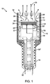
図1に示されるように、好ましい実施形態のエネルギー送達システム10は、切除エネルギーの供給源を提供するように機能を果たすエネルギー源12と、エネルギー源12に連結され、エネルギー源12がエネルギービーム20を放出するようにエネルギー源12に電力を通す機能を果たす電気的アタッチメント14および14’とを含む。好ましい実施形態のエネルギー送達システム10はまた、センサを含み、かつ/または、エネルギー源12は、間隙(エネルギー源12からの組織表面の距離)と、切除の標的とされる組織の厚さと、切除された組織の特性と、組織および/またはエネルギー送達システム10の周りの環境の任意の他の適切なパラメータまたは特性とを検出するようにさらに機能を果たす。好ましい実施形態のエネルギー送達システム10はまた、プロセッサ(図示されていない)を含み、該プロセッサは、電気的アタッチメント14を介してセンサに連結され、電気的アタッチメント14、および/またはセンサ40からの情報に基づいて電気的アタッチメント14に送達される電気信号を制御する。エネルギー送達システム10は、患者の心房細動の治療のために、好ましくはエネルギーを組織に送達するように設計され、より具体的には、心臓組織などの組織に切除エネルギーを送達し、伝導ブロック−典型的には左心房の肺静脈から起る異常な電気的活動の伝導経路の絶縁および/またはブロックを作るように設計される。しかしながら、システム10は、代わりに、任意の適切な環境において任意の適切な理由で任意の適切な組織に対して用いられ得る。
As shown in FIG. 1, the
エネルギー源。図1に示されるように、好ましい実施形態のエネルギー源12は、切除エネルギーの供給源を提供し、エネルギービーム20を放出するように機能を果たす。エネルギー源12は、好ましくは、患者内、好ましくは患者の心臓の左心房内において動かされ、位置を決められ、その結果、エネルギー源12は、標的組織に対して、適切な角度および(本明細書において「間隙」として定義される)距離で位置を決められる。角度は、放射されたエネルギービーム20が標的組織の中に伝わり、好ましくは、経壁外傷(すなわち、以下に説明されるように、組織の厚さを貫く外傷であって、該外傷は好ましくは伝導ブロックを作る、外傷)を生成するように、任意の適切な角度および間隙である。40度〜140度の角度が好ましい。なぜなら、この範囲において、エネルギービームの大部分は好ましくは組織の中に伝わり、経壁を達成するのに必要とされる外傷深さは好ましくは理想的な直角から最小限に増加させられるからである。0mm〜30mmの間隙が好ましい。なぜなら、この範囲において、ビームのエネルギー密度は経壁外傷を達成するのに十分であるからである。
Energy source. As shown in FIG. 1, the preferred
図1に示されるように、エネルギー源12は、好ましくはハウジング16に連結される。エネルギー源12およびハウジング16は、好ましくは患者内に位置決め可能である。例えば、ハウジング16およびハウジング16内のエネルギー源12は、好ましくは心臓の左心房内(または任意の他の適切な位置)に動かされ、一旦そこに位置を決められると、好ましくは、エネルギー源12および放出されたエネルギービーム20を適切な角度および間隙で標的組織の方に向けるように動かされる。アセンブリ10のハウジング16はさらに、エネルギー源12の面と心臓の心房内などの患者内にある血液との間の障壁を提供するように機能を果たす。流体の流れがアセンブリ内に組み込まれていない場合、トランスデューサ面は血液と直接接触し、血液はエネルギー源12の表面において凝固する。さらに、エネルギー源12と周囲の血液との間の界面に血塊を形成する可能性がある。冷却流体28の流れは、血液がエネルギー源12と接触しないように保ち、よって血塊の形成を回避する。流量は、好ましくは分当たり1mlであるが、代わりに、流体柱を維持し、血液とエネルギー源12の面との分離を保ち、エネルギー源12を冷却し、かつ/または治療されている組織を冷却する、任意の他の適切な流量であり得る。
As shown in FIG. 1, the
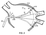
さらに、ハウジング16およびハウジング16内のエネルギー源12は、好ましくは、エネルギー源12が切除経路に沿って部分的または完全な切除帯を提供するように、切除経路に沿って動かされる。切除経路に沿った切除帯は、好ましくは、任意の適切な外形を有し、患者の心房細動の治療のための伝導ブロックを提供することなど、療法を提供する。切除経路に沿った切除帯は、代わりに患者のための任意の他の適切な療法を提供し得る。代わりに、切除は、単一のスポットまたは非常に小さい円であり得、電気的活動の焦点源を切除する。直線の切除経路は、好ましくは、X、Y、および/またはZ軸に沿ってハウジング16およびハウジング16内のエネルギー源12を動かすことによって作られる。図2に示されるように、細長い部材18のガイドシース部分GSの中へそして細長い部材18のガイドシース部分GSから外への細長い部材18の遠位部分の動きは、z軸によって表される。概ね円形または楕円形の切除経路は、好ましくは、軸(例えば、図2のワイヤWによって規定されるような軸)の周りにエネルギー源12を回転させることによって作られる。細長い部材18は、ハウジング16およびエネルギー源12と共に、好ましくは、図2に示されるように回転させられる。代わりに、他の構成においてエネルギー源12は、ハウジング16内において回転させられる。例えば、図2に示されるように、ハウジング16は心房の壁組織2174の方に向く。ハウジング16内のエネルギー源12は、エネルギービームを放出し、切除窓2172を確立する。ハウジング16(および下記に説明される細長い部材18)は、(図2における矢印2124によって示されるように)回転させられるので、切除窓2172は、概ね円形の切除経路2176を掃引し、円錐形シェルの断面を作る。さらにこの例において、Z軸に沿って前後に細長い部材を動かし、解剖学的構造における起こり得る変化に対して調整することが望まれ得る。切除経路は好ましくは直線または円形であるが、X、Y、Z軸の方向の動きと回転の動きとの任意の適切な組み合わせによって、任意の適切な切除経路が作られ得る。
Further, the
図1に示されるように、好ましい実施形態のエネルギー送達システム10はまた、エネルギー源12に連結された細長い部材18を含み得る。細長い部材18は、好ましくは可撓性の複数内腔管(multi−lumen tube)から作られるカテーテルであるが、代わりに、カニューレ、管または1つ以上の内腔を有する任意の他の適切な細長い構造であり得る。好ましい実施形態の細長い部材18は、プルワイヤ、流体、気体、エネルギー送達構造、電気ワイヤ、治療カテーテル、誘導(navigation)カテーテル、ペーシング(pacing)カテーテル、連結部および/または任意の他の適切なデバイスまたは要素を収容するように機能を果たす。図1に示されるように、細長い部材18は、好ましくは、細長い部材18の遠位部分に位置を決められるハウジング16を含む。細長い部材18はさらに、患者内においてエネルギー源12および/またはハウジング16を動かし、そしてそれらの位置を決めるように機能を果たし、その結果、放出されたエネルギービーム20は、適切な角度および間隙で標的組織の中に伝わり、エネルギー源12および/またはハウジング16は、エネルギー源12が切除経路に沿って部分的または完全な切除帯を提供するように切除経路に沿って動かされる。
As shown in FIG. 1, the preferred embodiment
エネルギー源12は、好ましくは、超音波ビームを放出する超音波トランスデューサであるが、代わりに切除エネルギーの供給源を提供するように機能を果たす任意の適切なエネルギー源であり得る。切除エネルギーの適切な供給源は、無線周波数(RF)エネルギーと、マイクロ波と、フォトニックエネルギーと、熱エネルギーとを含むがこれらに限定されない。療法は、代わりに冷却された源(例えば、低温流体)を用いて達成され得る。エネルギー送達システム10は、好ましくは単一のエネルギー源12を含むが、代わりに任意の適切な数のエネルギー源12を含み得る。超音波トランスデューサは、好ましくは、PZT(ジルコン酸チタン酸鉛)もしくはPVDF(フッ化ポリビニリデン二フッ化物(polyvinylidine difluoride))などの圧電材料、または任意の他の適切な超音波ビーム放出材料から作られる。単純にするためにトランスデューサの前面は、好ましくは平らであるが、代わりに凹形または凸形のいずれかなどのより複雑な外形を有し得、レンズの効果を達成するかまたはアポディゼーション−トランスデューサの表面の一部分もしくは複数の部分の振動を選択可能に減少させる−およびエネルギービーム20の伝達の管理を支援し得る。トランスデューサは、好ましくは円形の外形を有するが、代わりに楕円形、多角形、または任意の他の形状を有する。トランスデューサは、適切な材料の好ましくは薄い層であるコーティング層をさらに含み得る。いくつかの適切なトランスデューサコーティング材料は、グラファイト、金属被覆グラファイト、金、ステンレス鋼、ニッケルカドミウム、銀、金属合金、およびアマルガムまたは適切な材料の複合物を含み得る。例えば、図1に示されるように、エネルギー源12の前面は、好ましくは1つ以上の音響整合層34に連結される。単数または複数の整合層は、エネルギービーム20を周囲の流体28に連結する効率を増加させるように機能を果たす。整合層34は、好ましくは蒸着技術によってトランスデューサ面に配置される、パリレンなどのプラスチックから好ましくは作られるが、代わりに、グラファイト、金属被覆グラファイト、セラミック、または任意の適切な方法でトランスデューサに加えられる複合物などの任意の適切な材料であり得る。
The
エネルギー源12は、好ましくはいくつかの変種のうちの1つであり得る。第1の変種において、図3に示されるように、エネルギー源12は、平らな前表面を有するディスクである。第2の変種において、図4Aおよび図4Bに示されるように、エネルギー源12’は、不活動部分42を含む。この変種において、不活動部分42は、エネルギー源12が電力を通されたとき、エネルギーを放出しないか、または代わりに非常に低い(実質的に0)エネルギーを有するエネルギービームを放出し得る。不活動部分42は、好ましくは、エネルギー源の温度調節、すなわちエネルギーが熱くなり過ぎるのを防ぐことを支援するように機能を果たす。フルディスクトランスデューサにおいて、図3に示されるように、トランスデューサの中心部分は、電力が通されている間、概してトランスデューサの最も熱い部分となる。トランスデューサの中心部分またはトランスデューサの中心部分の一部分を除去することによって、トランスデューサから放出されるエネルギーは好ましくはトランスデューサの全体に異なって分配され、トランスデューサの熱は好ましくはより容易に消散される。
The
不活動部分42は、好ましくはエネルギー源12’によって規定される穴または間隙である。この変種において、冷却液源は、エネルギー源12’に連結され得るか、または冷却流体の場合、冷却流体は、エネルギー源12’によって規定される穴または間隙を通って流れ得、エネルギー源12’をさらに冷却し、エネルギー源12’の温度を調整し得る。不活動部分42は、代わりに、エネルギー源12’の材料特性とは異なる材料特性を有する材料から作られ得る。例えば、材料は、好ましくは、エネルギー源12から熱をそらすかまたはエネルギー源12から離れるように熱を伝える機能を果たす、銅などの金属である。代わりに、不活動部分はエネルギー源12と同じ材料から作られるが、電極めっきが電気的アタッチメント14およびまたは発電機から除去されるかまたは断絶させられる。不活動部分42は、好ましくはエネルギー源12’の全厚さに沿って配置されるが、代わりに、エネルギー源12’の全厚さより少ない厚さを有する、エネルギー源12’上の材料またはエネルギー源12’内の材料の層であり得る。図4Aに示されるように、エネルギー源12’は、好ましくはドーナツ形トランスデューサである。示されるように、トランスデューサは、好ましくはトランスデューサの中心部分に穴(または不活動部分42)を規定する。この変種のエネルギー源12’は、好ましくは円形の外形を有するが、代わりに、楕円形、多角形(図4B)、または任意の他の適切な形状であり得る。エネルギー源12’は、好ましくは単数の円形不活動部分42を含むが、代わりに、図4Bに示されるように、任意の適切な外形の任意の適切な数の不活動部分42を含み得る。エネルギー源12から放出される全エネルギーは、活動的である(すなわち、エネルギービーム20を放出する)エネルギー源12の表面積に関係する。従って、エネルギー源12が可能な限り多くの出力エネルギーを提供するかまたは所望により出力エネルギーを提供することを可能にしながら、不活動部分42の大きさおよび位置は、好ましくはエネルギー源12における熱生成を減少させる。
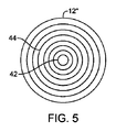
第3の変種において図5に示されるように、エネルギー源12”は、好ましくは複数の環状のトランスデューサ44を含む。複数の環状のトランスデューサは、好ましくは複数の同心リングであるが、代わりに楕円形または多角形などの任意の適切な外形を有する任意の適切な構成を有し得る。エネルギー源12”は、図5に示されるようにエネルギー源12”の中心部分などの不活動部分42をさらに含み得る。複数の環状トランスデューサ44は、好ましくは、少なくとも第1の環状のトランスデューサと、第2の環状のトランスデューサとを含む。第1の環状のトランスデューサは、好ましくは第2の環状のトランスデューサの材料特性とは異なる材料特性を有し、その結果、第1の環状のトランスデューサは、第2の環状のリングから放出される第2のエネルギービームとは異なる第1のエネルギービームを放出する。さらに、第1の環状のトランスデューサは、第2の環状のトランスデューサとは異なる周波数、位相、電圧、デューティサイクル、出力によって、かつ/または異なる時間長で電力を通され得る。代わりに第1の環状のリングは、第2の環状のリングとは異なるモードで動作させられ得る。例えば、第1の環状のリングは、組織を加熱するのに十分な超音波のパルスを送達する切除モードなどの療法モードで作動させられ得、一方、第2の環状リングはAモードなどの診断モードで作動させられ得、該診断モードは短い継続時間の超音波のパルスを送達し、該短い継続時間の超音波のパルスは、概して、組織を加熱するのに十分ではないが、標的組織および/またはエネルギー送達システムにおける環境およびエネルギー送達システムの周りの環境の特性を検出する機能を果たす。第1の環状のトランスデューサは、第2の環状のトランスデューサの電気的アタッチメントとは別個の電気的アタッチメント14をさらに含み得る。代わりに、環状のリングは、適切な電気信号によって電力を通され得、その結果、適切な電気信号は、所望の切除性能のビームに従ってエネルギー密度を最適化するためにビーム20を形作る。
As shown in FIG. 5 in the third variant, the
第4の変種において図6に示されるように、エネルギー源12”’は、好ましくはトランスデューサ部分46のグリッドを含む。トランスデューサ部分46のグリッドは、好ましくは、円形、長方形(図6に示されるように)、楕円形、多角形、または任意の他の適切な外形などの任意の適切な外形を有する。この変種のエネルギー源12”’は、エネルギー源12’の第2の変種において説明されるような不活動部分などの不活動であるトランスデューサ部分をさらに含み得る。トランスデューサ部分46のグリッドは、好ましくは、少なくとも第1のトランスデューサ部分と、第2のトランスデューサ部分とを含む。第1のバージョンにおいて、第1のトランスデューサ部分および第2のトランスデューサ部分は、好ましくは一式の材料特性を有する単一のトランスデューサの複数の部分である。第1のトランスデューサ部分は、好ましくは、第2のトランスデューサ部分とは異なる周波数、位相、電圧、デューティサイクル、出力によって、かつ/または異なる時間長で電力を通される。さらに第1のトランスデューサ部分は、第2のトランスデューサ部分とは異なるモードで動作させられ得る。例えば、第1のトランスデューサ部分は、切除モードなどの療法モードで動作し得、一方、第2のトランスデューサはAモードなどの診断モードで動作し得る。このバージョンにおいて、第1のトランスデューサ部分は、第2のトランスデューサ部分の電気的アタッチメントとは別個の電気的アタッチメント14をさらに含む。例えば、第1のトランスデューサ部分は、エネルギー源12”’の中心の方に位置を定められ得、第2のトランスデューサ部分は、エネルギー源12”’の外側部分の方に位置を定められ得、第2のトランスデューサ部分は電力を通され得、一方、第1のトランスデューサ部分は不活動のままである。第2のバージョンにおいて、第1のトランスデューサ部分は、好ましくは第2のトランスデューサ部分の材料特性とは異なる材料特性を有し、その結果、第1のトランスデューサ部分は、第2のトランスデューサ部分から放出される第2のエネルギービームとは異なる第1のエネルギービームを放出する。このバージョンにおいて、第1のトランスデューサ部分はまた、第2のトランスデューサ部分とは異なる周波数、電圧、デューティサイクル、出力によって、かつ/または異なる時間長で電力を通され得る。代わりに、エネルギービーム20の形状は、適切な電気信号によって駆動される適切なトランスデューサ部分を用いて修正され得る。この一例は、一般的に整相列ビーム形成(phase array beam forming)と呼ばれる。
As shown in FIG. 6 in the fourth variant, the
電気的アタッチメント。図1に示されるように、好ましい実施形態の電気的アタッチメント14は、エネルギー源12がエネルギービーム20を放出するようにエネルギー源12の電力を通すように機能を果たす。使用時、エネルギー源12が電力を通されると、エネルギー源12は、標的組織の方にエネルギービーム20を放出する。エネルギーがエネルギービーム20から組織の中に移動させられると、標的組織部分は、好ましくは切除を達成するほど十分に加熱される。図1に示されるように、電気的アタッチメント14は、好ましくはエネルギー源12に連結される。エネルギー送達システム10は、好ましくは2つの電気的アタッチメント14および14’を含むが、代わりにエネルギー源12の電力を通すために任意の適切な数の電気的アタッチメントを含み得る。エネルギー源12は、好ましくは第1の電気的アタッチメント14を有し、第1の電気的アタッチメント14は、適切に絶縁されたワイヤ38に連結されるエネルギー源12の前表面に連結される。電気的アタッチメント14は、好ましくは、はんだ、ワイヤボンディング、伝導性エポキシ、またはスエージなどの標準のボンディング技術によって達成される。電気的アタッチメント14は、好ましくは、電力を通されたときエネルギー源12によって放出されるエネルギービーム20を妨害しないように、エネルギー源12のエッジのより近くに配置される。エネルギー源12は、好ましくは第2の電気的アタッチメント14’を有し、第2の電気的アタッチメント14’は、適切に絶縁されたワイヤ38’に連結されるエネルギー源12の後面に連結される。ワイヤ38および38’は、一緒にして対線(pair)38”を形成し、対線38”は、好ましくは、撚りシールド対線(twisted shielded pair)、ミニチュア同軸ケーブル、金属管ブレード(metal tube braid)であるか、または任意の他の適切な方法で連結される。電気的アタッチメント14は、代わりに、任意の他の適切な方法で任意の他の適切な構成で、エネルギー源12に連結され得る。
Electrical attachment. As shown in FIG. 1, the
好ましい実施形態のエネルギー送達システム10はまた、単数または複数の電気的アタッチメント14を介してエネルギー源12に電力を提供するように機能する発電機(図示されていない)を含む。エネルギー源12は、好ましくは、適切に絶縁されたワイヤ38および38’によって発電機に連結され、ワイヤ38および38’は、エネルギー源12の2つの面に連結される電気的アタッチメント14および14’に接続される。発電機によって電力を通されたとき、エネルギー源12は、エネルギーを放出する。発電機は、エネルギー源12に適切な信号を提供し、所望のエネルギービーム20を作る。周波数は、好ましくは1MHz〜30MHzの範囲であり、より好ましくは5MHz〜25MHzの範囲である。エネルギービーム20のエネルギーは、エネルギー源12に印加される励振電圧と、デューティサイクルと、電圧が印加される総時間とによって決定される。電圧は、好ましくは5ボルト〜200ボルトピークピークの範囲である。さらに可変デューティサイクルは、好ましくは、エネルギー源12に送達される平均電力を制御するために用いられる。デューティサイクルは好ましくは0%〜100%の範囲であり、繰返し周波数は好ましくは組織における熱伝導の時定数より速い。そのような適切な繰返し周波数の1つは、約40kHzである。
The
エネルギービームと組織との相互作用。電気信号または電気的アタッチメント14および/または14’によるパルス列によって電力を通されたとき、エネルギー源12は、エネルギービーム20(音圧波など)を放出する。エネルギービーム20の特性(properties)は、エネルギー源12、整合層34、バッキング22(以下に説明される)、および電気的アタッチメント14からの電気信号の特性(characteristics)によって決定される。これらの要素は、組織の中に伝えられるエネルギービーム20(音波など)の周波数、帯域幅、ビームパターン、および振幅を決定する。図7に示されるように、エネルギー源12は、エネルギービーム20が組織276と相互に作用するようにエネルギービーム20を放出し、外傷(切除帯278)を形成する。エネルギービーム20は、好ましくは超音波ビームである。組織276の前表面280は、ハウジング16の面から距離d(282)だけ離れている。エネルギービーム20が組織276を通って進むと、エネルギービーム20のエネルギーは、組織276によって吸収され、散乱させられ、切除エネルギーのほとんどは熱エネルギーに変換される。この熱エネルギーは、周囲の組織より高い温度に組織を加熱し、その結果、加熱帯278をもたらす。組織が加熱される帯278において、組織細胞は好ましくは熱によって死なされる。組織の温度は好ましくは加熱帯278において細胞死が起る温度より高く、従って、組織が切除されたと言われる。従って組織278は、好ましくは切除帯または外傷として参照される。
Interaction of energy beam with tissue. When energized by a pulse train with an electrical signal or
外傷の物理的特性。エネルギービーム20によって形成される外傷または切除帯278の形状は、エネルギービーム20、エネルギー源12(材料、形状、電力を通されかつ/または電力を通されないエネルギー源12の部分などを含む)、整合層34、バッキング22(下記に説明される)、電気的アタッチメント14からの電気信号(周波数、電圧、デューティサイクル、信号の長さおよび形状などを含む)、ならびにビーム20が伝わる標的組織の特性および接触もしくは休止時間の長さなどの適切な組み合わせ要因の特性に依存する。標的組織の特性は、熱移動特性と、標的組織および周囲の組織の超音波の吸収、減衰および後方散乱の特性とを含む。
The physical characteristics of the trauma. The shape of the trauma or
エネルギービーム20によって形成される外傷または切除帯278の形状は、好ましくはエネルギー源12によるいくつかの変種のうちの1つである(材料、形状、電力を通されかつ/または電力を通されないエネルギー源12の部分などを含む)。切除帯278の第1の変種において図7に示されるように、エネルギー源12はフルディスクトランスデューサであり、切除帯278は涙のしずく形の外傷である。帯278の直径D1は、組織表面280におけるビーム20の直径Dより小さく、さらに組織276の単数または複数の外側層276’は、好ましくは実質的に損傷されないままである。これは、組織表面280を通過して流れる周囲の流体(冷却流体および/または血液)によって提供される熱冷却による。組織276の外側層276’は、多かれ少なかれ、のがれさせられ得るか、または組織表面280が冷却される量および/またはエネルギー送達システム10(エネルギー源12とエネルギービーム20とを含む)の特性により実質的に損傷されないままであり得る。切除帯278に堆積されるエネルギーは、好ましくは組織の単数または複数の表面下層と相互に作用し、その結果、心臓内表面は、本来の状態の(かつ/または炭化されない)ままである。エネルギービーム20が組織の中にさらに深く進むと、表面における熱冷却ほど効率的ではない熱冷却が周囲の組織によって提供される。結果として、周囲の組織の熱移動特性ならびにビーム20からのエネルギーの継続した入力によって決定されるように、切除帯278は、直径D1より大きいD2を有する。長時間ビーム20が組織に向けられると、切除帯278は、組織の中に延びるが、無限ではない。切除帯278の深さ288には自然の限界があり、これは、エネルギービーム20が組織の中に伝わるときの超音波エネルギーの減衰および吸収、健康な周囲の組織によって提供される熱移動、および平行長さ(collimated length)Lを超えるビームの広がりなどの要因によって決定されるからである。この超音波と組織との相互作用中、超音波エネルギーは、組織によって吸収され、従って、超音波エネルギーが組織の中にさらに進むと、利用可能な超音波エネルギーはますます少なくなる。従って対応するより小さい直径の加熱帯が組織に発現させられ、全体的な結果として、加熱切除帯278の形成となり、加熱切除帯は、組織の中の深さ288までの限定された細長い涙の形状である。
The shape of the trauma or
第2の変種において図9に示されるように、切除帯278’はより短い深さ288’を有する。この変種において、外傷は、好ましくは切除帯278(図7)より鈍い形状を有する。この第2の変種の1つの起り得る外傷の形状は、図9に示されるように歯形の形状であり得るが、代わりに鈍い涙形、円形、または楕円形などの任意の適切な形状を有し得る。図9に示されるように、帯278’(図7の帯278に類似する)は、組織表面280を通過して流れる周囲の流体によって提供される熱冷却により、組織表面280においてビーム20の直径Dより小さい帯278の直径D1を有する。この変種において、エネルギー源12’は、好ましくはエネルギー源12の中心に位置を定められる不活動部分42を有し、その結果、エネルギー源は、第1の変種(図7)のエネルギービーム20より広くより平らな輪郭を有し概してより拡散したエネルギービーム20を放出するドーナツ形のトランスデューサである。図9に示されるようなドーナツ形のトランスデューサから放出されるエネルギービーム20は、好ましくはエネルギービームの中線に沿った減少ピーク強度を有する(図9において点線によって断面で示されるように)。この超音波組織の相互作用によって、エネルギービームの中線に沿った減少ピーク強度は、組織によって吸収されており、超音波エネルギーが組織の中にさらに進むと、利用可能な超音波エネルギーはますます少なくなり、第1の変種の場合よりも鈍い外傷を形成する。
As shown in FIG. 9 in the second variant, the ablation zone 278 'has a shorter depth 288'. In this variant, the trauma preferably has a duller shape than the ablation zone 278 (FIG. 7). The possible trauma shape of one of the second variants can be a tooth shape as shown in FIG. 9, but instead has any suitable shape such as a blunt tear, circle, or ellipse. Can do. As shown in FIG. 9, the
切除帯278の大きさおよび特性はまた、所望のエネルギービーム20を作るためにエネルギー源12に印加される周波数および電圧に依存する。例えば、周波数が増加すると、超音波エネルギーの組織の中への貫入の深さは減少させられ、結果として、より浅い深さ288の切除帯278(図7)をもたらす。周波数は、好ましくは1MHz〜30MHzの範囲であり、より好ましくは5MHz〜25MHzの範囲である。エネルギービーム20のエネルギーは、例えばPZT材料から製作されるトランスデューサのためのエネルギー源12に印加される励振電圧によって決定される。電圧は、好ましくは50ボルト〜200ボルトピークピークの範囲である。さらに、可変デューティサイクルは、好ましくはエネルギー源12に送達される平均電力を制御するために用いられる。デューティサイクルは好ましくは0%〜100%の範囲であり、繰返し周波数は約40kHzであり、この周波数は、好ましくは組織における熱伝導の時定数より速い。約2.5mm直径のエネルギー源12に印加されたとき、結果として切除帯278をもたらし、切除帯278は、1秒〜5秒で作られ、好ましくは0.3ワット〜10ワット、より好ましくは2ワット〜6ワットの平均音響出力レベルに対して、約5mmの深さ288およびエネルギー源12の直径に一致して約2.5mmの最大直径を有する。
The size and characteristics of the
切除帯278の大きさおよび特性はまた、図8A〜図8Dに示されるように、標的組織がエネルギービーム20によって接触される時間に依存し、図8A〜図8Dは、時間t1、t2、t3、t4それぞれにおいて外傷の形成を例示する。組織における切除帯278は、組織における超音波エネルギーから熱エネルギーへの変換によって形成される。ビーム20におけるエネルギー密度が時間t1において組織276の前表面280の近くで最高であるので、熱が形成され、これが外傷278を形成し始める(図8A)。時間がt2およびt3に経過すると(図8Bおよび図8C)、さらなるエネルギーが組織の中に送達され、その結果、切除帯278は直径および深さにおいて成長し続ける。t1〜t3のこの時間順序は、好ましくは超音波エネルギー密度に従ってわずか1秒〜5秒かかるだけである。超音波ビームの入射が時間t3を超えて続けられると、切除外傷278は、直径および長さにおいてわずかに成長し、次いで、周囲の組織の中への熱エネルギーの消散によって平衡を保たれるエネルギーの超音波形態から熱形態へのエネルギー移動において達成される安定した状態により、成長を止める。図8Dに示される例は、約30秒間のエネルギービームへの露出t4後の外傷を示す。従って、外傷は、大きさにおいて自然の限界に達し、無限には成長しない。
The size and characteristics of the
超音波エネルギー密度は、好ましくは切除が発生する速度を決定する。ビーム20の断面積で割った、エネルギー源12によって送達される音響出力は、単位時間当たりのエネルギー密度を決定する。効果的な音響出力は、好ましくは0.3ワット〜10ワット未満の範囲であり、対応する出力密度は、好ましくは6ワット/cm2〜200ワット/cm2未満の範囲である。これらの出力密度は、切除帯において発現させられる。ビームが切除帯を超えて広がると、時間露出に関わらず切除が発生しないように出力密度は降下する。
切除帯278の形状は、好ましくはいくつかの変種のうちの1つであるが、切除帯278の形状は、任意の適切な形状であり得、エネルギービーム20、エネルギー源12(材料、形状などを含む)、整合層34、バッキング22(下記に説明される)、電気的アタッチメント14からの電気信号(周波数、電圧、デューティサイクル、パルスの長さなどを含む)、ならびにビーム20が伝わる標的組織および接触もしくは休止時間の長さの任意の適切な組み合わせによる任意の適切な方法で変更され得る。
The ultrasonic energy density preferably determines the rate at which ablation occurs. The acoustic power delivered by the
The shape of the
センサ。好ましい実施形態のエネルギー送達システム10はまた、センサを含み、かつ/または、エネルギー源12は、間隙(エネルギー源12からの組織表面の距離)と、切除の標的とされる組織の厚さと、切除された組織の特性と、入射ビーム角度と、組織および/または、温度など、エネルギー送達システム10の周りの環境の任意の他の適切なパラメータもしくは特性とを検出するようにさらに機能を果たす。情報を検出することによって、センサ(以下に説明されるように、プロセッサに連結されるセンサ)は、好ましくは、組織の切除によって提供される療法を導くように機能を果たす。
Sensor. The
センサは、好ましくはいくつかの変種のうちの1つである。第1の変種において、センサは、好ましくは、間隙、切除の標的とされる組織の厚さ、切除された組織の特性、および任意の他の適切なパラメータまたは特性に関する情報を検出するように機能を果たす超音波トランスデューサである。センサは、好ましくはエネルギー源12と実質的に同一の形状を有し、センサによって診断される領域がエネルギー源12によって治療されるべき領域と実質的に同一であることを確実にする。より好ましくは、センサは、エネルギー源のトランスデューサと同じトランスデューサであり、エネルギー源12は、異なるモード(下記に定義されるAモードなど)で動作することによって情報を検出するようにさらに機能を果たす。
The sensor is preferably one of several variants. In the first variant, the sensor preferably functions to detect information regarding the gap, the thickness of the tissue targeted for ablation, the characteristics of the ablated tissue, and any other suitable parameter or characteristic. It is an ultrasonic transducer that fulfills The sensor preferably has substantially the same shape as the
第1の変種のセンサは、好ましくは、概して組織を加熱するのに十分ではない短い継続時間の超音波のバーストを利用する。これは、当該分野においてAモードまたは振幅モード像(Amplitude Mode imaging)と呼ばれる単純な超音波画像化技術である。図10に示されるように、センサ40は、好ましくは超音波のバースト290を組織276の方に送る。ビームの一部分は、組織276の前表面280および前表面280における組織から292として反射されかつ/または後方散乱させられる。この戻り音波292は、短時間後にセンサ40によって検出され、電気信号に変換され、該電気信号は、電気受信器(図示されていない)に送られる。戻り音波292は、音がセンサ40から組織276の前境界280および前境界280の近くの組織276に進み、センサ40に戻るのにかかる時間だけ遅延する。この進行時間は、センサ40から電気信号を受信するときの遅延を表す。介在媒体(流体286および血液284)における音の速度に基づいて、間隙距離d(282)に関する情報が検出される。音ビームがさらに組織276の中に進むと、音ビームの一部分293は、形成されている外傷278から散乱させられ、センサ40の方に進む。再びセンサ40は、この音エネルギーを電気信号に変換し、プロセッサ(以下に説明される)は、この情報を外傷の深さなどの外傷形成の特性に変換する。音ビームが組織276の中になおもさらに進むと、組織276の一部分294は、後表面298から反射され、トランスデューサの方に進む。再びセンサ40は、この音エネルギーを電気信号に変換し、プロセッサは、超音波バースト290の入射の地点においてこの情報を組織276の厚さt(300)に変換する。カテーテルハウジング16は、組織を横切るような方法301で横断されるので、センサ40は、間隙d(282)と、外傷特性と、組織の厚さt(300)とを検出する。センサは、好ましくはこれらのパラメータを連続的に検出するが、代わりにこれらのパラメータを定期的または任意の他の適切な方法で検出し得る。この情報は、以下に考察されるように、療法中に組織276の切除を管理するために用いられる。
The first variant sensor preferably utilizes a short duration burst of ultrasound that is generally not sufficient to heat the tissue. This is a simple ultrasound imaging technique referred to in the art as A-mode or Amplitude Mode imaging. As shown in FIG. 10, the
第2の変種において、センサは、温度センサであり、該温度センサは、標的組織、周囲の環境、エネルギー源12、以下に説明されるように冷却流体の温度、および/または任意の他の適切な要素もしくは領域の温度を検出するように機能を果たす。温度センサは、好ましくは熱電対であるが、代わりに、サーミスタまたは赤外線温度センサなどの任意の適切なセンサであり得る。センサによって集められたこの温度情報は、以下に考察されるように、好ましくは、療法中に組織276の切除を管理し、標的組織および/またはエネルギー送達システム10の温度を管理するために用いられる。
In the second variant, the sensor is a temperature sensor, which is the target tissue, the surrounding environment, the
プロセッサ。好ましい実施形態のエネルギー送達システム10はまた、センサ40および電気的アタッチメント14に連結されたプロセッサを含み、該プロセッサは、センサ40からの情報に基づいて電気的アタッチメント14および/または電気的アタッチメント14に送達される電気信号を制御する。プロセッサは、好ましくは従来のプロセッサであるが、代わりに所望の機能を実行する任意の適切なデバイスであり得る。
Processor. The
プロセッサは、好ましくは、間隙距離、切除標的組織の厚さ、切除組織の特性、および任意の他の適切なパラメータまたは特性に関する情報などの情報をセンサから受信する。この情報に基づいて、プロセッサは、好ましくは、周波数、電圧、デューティサイクル、パルスの長さおよび/または任意の他の適切なパラメータなどの、電気的アタッチメント14を介してエネルギー源12に送られる伝記信号を修正することによって、エネルギー源12から放出されるエネルギービーム20を制御する。プロセッサはまた、エネルギー源12のどの部分が電力を通されかつ/またはどの周波数、電圧、デューティサイクルなどで電力を通されるかを制御することによって、エネルギービーム20を制御する。エネルギー源12の種々の部分は、上記に説明されるように、エネルギー源12”および12”’のそれぞれの複数の環状のトランスデューサ44およびドランスデューサ部分46のグリッドに対して電力を通され得る。さらにプロセッサは、流体の流れコントローラにさらに連結され得る。プロセッサは、好ましくは、切除組織、未切除組織もしくは標的組織の特性、組織および/またはエネルギー源の温度、ならびに/または任意の他の適切な状態のセンサ検出特性に基づいて、流体の流れを増加させるかまたは減少させるように流体の流れを制御する。
The processor preferably receives information from the sensor, such as information regarding gap distance, ablation target tissue thickness, ablation tissue characteristics, and any other suitable parameters or characteristics. Based on this information, the processor preferably sends the biography sent to the
エネルギービーム20を制御すること(および/または標的組織もしくはエネルギー源12を冷却すること)によって、切除帯278の形状が制御される。例えば、切除帯の深さ288は、好ましくは、経壁外傷(組織の厚さを貫く外傷)が達成されるように制御される。さらにプロセッサは、好ましくは、標的組織を越えて、例えば外側心房壁を越えて、外傷を作る可能性を最小限するように機能を果たす。センサが心房の外側壁を越えて延びる外傷および/または切除窓2172(図2に示されるように)を検出するか、または外傷の深さが事前設定の深さに達するかもしくはそれを超えた場合、プロセッサは、好ましくは、発電機の電源を切りかつ/または電気的アタッチメント14、14’に電気信号を送るのを停止する。
By controlling the energy beam 20 (and / or cooling the target tissue or energy source 12), the shape of the
さらに、プロセッサは、好ましくは、好ましい間隙距離を維持するように機能を果たす。間隙距離は、好ましくは0mm〜30mm、より好ましくは1mm〜20mmである。切除窓2172(図2に示されるように)が心房の外側壁に達しないことをセンサが検出した場合、プロセッサは好ましくはエネルギー送達システムを再位置決めする。例えば、ハウジング16(および、下記に説明される細長い部材18)が回転させられると(図2の矢印2124によって示されるように)、切除窓2172は、好ましくは、概ね円形の切除経路2176を掃引し、円錐形シェルの断面を作る。しかしながら、切除窓2172が心房の壁に達しないことをセンサが決定した場合、プロセッサは、好ましくは、細長い部材をZ軸に沿って前後に動かすか、または解剖学的構造において起こり得る変種に対して調整するために細長い部材が動かされるべきであることを示す。この例において、術者は細長い部材を再位置決めし得るか、プロセッサは好ましくは細長い部材18の位置を決めるように機能を果たすモータ駆動ユニットまたは他の制御ユニットに連結される。さらに外傷の深さが所望の深さに達しないかまたは所望の深さを超えたかのいずれかをセンサが検出した場合、プロセッサは、好ましくは、エネルギー源12に送達される信号を調整し、かつ/またはビームが切除経路2176に沿って動く速度を調整し、それによって、組織におけるビームの休止時間を調整する。プロセッサがエネルギー源に送達される信号を調整する場合、プロセッサは外傷深さを修正するために出力および/または周波数を調整し得る。
Further, the processor preferably functions to maintain a preferred gap distance. The gap distance is preferably 0 mm to 30 mm, more preferably 1 mm to 20 mm. If the sensor detects that the ablation window 2172 (as shown in FIG. 2) does not reach the outer wall of the atrium, the processor preferably repositions the energy delivery system. For example, when the housing 16 (and the
追加の要素。図1および図3に示されるように、好ましい実施形態のエネルギー送達システム10はまた、エネルギー源12に連結されるバッキング22を含む。エネルギー源12は、好ましくは、接着リング24によってバッキング22の端部に接合される。バッキング22は、好ましくは金属またはプラスチックから作られ、その結果、バッキングはエネルギー源のための熱シンクを提供する。エネルギー源12は、エネルギー源12の後表面とバッキング22との間にポケット26が存在するように、バッキング22に取り付けられる。このポケットは、好ましくはエネルギー源12の材料とは実質的に異なる音響インピーダンスを有する材料を含み、好ましくは音響的反射表面を作る。別の方法ではエネルギー源12の後部から出る超音波のほとんどは、好ましくはポケットからエネルギー源12の中に戻るように再度向けられ、エネルギー源12の前表面を通って出る。さらにポケットの材料はまた、良好な熱導体であり、その結果、熱はエネルギー源から除去され得、ポケットが電気ワイヤをエネルギー源の後表面に接続するように、電導性である。ポケットは、好ましくはいくつかの変種のうちの1つである。第1のバージョンにおいて、バッキング22は、複数の点においてエネルギー源に連結する。例えば、バッキングは、好ましくは、エネルギー源12の大部分がバッキングの一部分に触れないように、好ましくは外側部分に連結する3つのポストを含む。この変種において、流体またはゲルは、エネルギー源12を通って流れ、好ましくはエネルギー源12の前表面および後表面の両方を浸す。第2の変種において、ポケットは、エネルギー源12の後表面とバッキング22との間のエアポケット26である。エアポケット26は、エネルギー源12が電気エネルギーの印加によって電力を通されると、放出されたエネルギービーム20がエアポケット26によって反射させられ、エネルギー源12から外に向けられるように、機能を果たす。バッキング22は、好ましくは円筒形のエアポケットを規定し、より好ましくは、環状の形状を有するエアポケットを規定する。バッキングは、バッキングが断面で見ると実質的に三脚の形状を有するように、中心ポストをさらに含むことによって環状のエアポケットを規定し、この場合、バッキングは、エネルギー源の外側部分およびエネルギー源の中心部分の両方の方に向かってエネルギー源12に連結される。エアポケット26は、代わりに、エネルギービーム20の実質的な部分がエネルギー源12から外側に向けられように任意の他の適切な材料によって取り替えられ得る。
Additional elements. As shown in FIGS. 1 and 3, the preferred embodiment
エネルギー源12は、エネルギービーム20を放出するが、エネルギー源は加熱されるようになり得る。エネルギー源12は、好ましくは、エネルギー源12を冷却することによって、安全な動作温度範囲内に維持される。エネルギー源12の冷却は、好ましくはエネルギー源12の温度と比較してより低い温度を有する、例えば食塩水などの流体、または任意の他の生理的に適合する流体とエネルギー源12を接触させることによって好ましくは達成される。第1のバージョンにおいて、流体の温度は、好ましくは、流体がトランスデューサおよび標的組織の両方を冷却するほど十分に冷たい。このバージョンにおいて、流体またはゲルの温度は、好ましくは−5℃〜5℃であり、より好ましくは実質的に0℃に等しい。第2のバージョンにおいて、流体の温度は、流体がエネルギー源12を冷却するが、しかしながら流体は標的組織を冷却しないで、実際は標的組織を暖め得るような温度範囲内である。流体は、代わりに、エネルギー源12を十分に冷却する任意の適切な温度であり得る。例として図3に示されるように、バッキング22は、好ましくは外壁に沿って長手方向に配置される一連の溝36を有し、それらの溝は、実質的にバッキング22の外側表面に沿って、エネルギー源12の面を通過する冷却流体28の流れを提供するように機能を果たす。一連の溝は、代わりに、らせん形などの任意の他の適切な形状でバッキングに沿って配置され得る。結果として生じる流体の流れ線は、図1に30として描かれる。冷却流体の流れは、内腔32を通って達成される。トランスデューサを冷却するために用いられる流体は、好ましくは、ハウジング16の端部を通るかまたは1つ以上のアパーチャを通ってハウジング16から出る。アパーチャは、好ましくは、格子、ふるい、穴、ドリップ穴、水抜き構造または任意の多数の適切なアパーチャである。流体は、好ましくは、ハウジング16を出て、標的組織と接触し、組織を冷却する。
The
好ましい実施形態のエネルギー送達システム10はまた、レンズを含み、該レンズは、エネルギー源12に連結され、エネルギービーム20のビームパターンを調整する際にさらなる可撓性を提供するように機能を果たす。レンズは、好ましくは標準の音響レンズであるが、代わりに、任意の適切な方法でエネルギービーム20を調整する任意の適切なレンズであり得る。例えば、音響レンズは、より一様に平行であるビームを作り得、その結果、最大ビーム幅D’はディスクDの直径に近づく。このことは、切除窓2172においてより一様なエネルギー密度を提供し、その結果、組織の深さが窓内において変化するので、より一様な外傷を提供する。レンズはまた、より浅いかまたはより深いかのいずれかの外傷を必要とし得る用途のために、最小ビーム幅D’の位置を動かすために用いられ得る。このレンズは、プラスチックまたは適切な音響特性を有する他の材料から製作され得、エネルギー源12の面に接合され得る。代わりに、エネルギー源12は、それ自体がレンズとして機能を果たすような形状を有し得るか、またはエネルギー源12の整合層もしくはコーティングがレンズとして機能を果たし得る。
The
簡潔さのため省略されているが、好ましい実施形態は、様々なエネルギー源12、電気的アタッチメント14、エネルギービーム20、センサ40、およびプロセッサのあらゆる組み合わせおよび入れ替えを含む。
Although omitted for brevity, preferred embodiments include any combination and replacement of
当業者は前述の詳細な説明ならびに図および特許請求の範囲から認識するように、修正および変更は、以下の特許請求の範囲に定義される本発明の範囲から逸脱することなく、本発明の好ましい実施形態に対してなされ得る。 Those skilled in the art will recognize from the foregoing detailed description and drawings and claims that modifications and changes may be made without departing from the scope of the invention as defined in the following claims. It can be made to the embodiment.
Claims (58)
近位端と遠位端とを有するハウジングと、
該ハウジングの該遠位端に隣接するエネルギー源であって、該エネルギー源は、活動部分と不活動部分とを有する、エネルギー源と
を備え、
該活動部分は、該エネルギー源に電力が通されたとき、組織にエネルギーを送達することによって、該組織に部分的な切除帯または完全な切除帯を作るように適合され、該切除帯は、該組織を通る異常な電気的活動をブロックし、該患者の心房細動を減少させるかまたは除去し、
該不活動部分は、該エネルギー源に電力が通されたとき、エネルギーを放出しないかまたは実質的にエネルギーを放出しない、デバイス。 An ablation device for treating atrial fibrillation in a patient, the device comprising:
A housing having a proximal end and a distal end;
An energy source adjacent to the distal end of the housing, the energy source comprising: an energy source having an active portion and an inactive portion;
The active portion is adapted to create a partial or complete ablation zone in the tissue by delivering energy to the tissue when power is passed to the energy source, Block abnormal electrical activity through the tissue and reduce or eliminate atrial fibrillation in the patient;
The device wherein the inactive portion does not release or substantially does not release energy when power is passed to the energy source.
近位端と、遠位端と、該遠位端に隣接するエネルギー源とを有するハウジングを提供することと、
該エネルギー源が該組織にエネルギーを送達するように該エネルギー源に電力を通すことであって、該エネルギー源は、活動部分と不活動部分とを備え、該活動部分は、該エネルギー源に電力を通されたとき該エネルギーを送達し、該不活動部分は、該エネルギー源に電力を通されたとき実質的にエネルギーを放出しない、ことと、
該組織において異常な電気的活動をブロックする切除帯を作ることによって、該患者の心房細動を減少させるかまたは除去することと
を包含する、方法。 A method of excising a patient's tissue as a treatment for atrial fibrillation comprising:
Providing a housing having a proximal end, a distal end, and an energy source adjacent to the distal end;
Passing power to the energy source such that the energy source delivers energy to the tissue, the energy source comprising an active portion and an inactive portion, the active portion powering the energy source Delivering the energy when passed through, and the inactive portion does not substantially release energy when powered through the energy source;
Reducing or eliminating atrial fibrillation in the patient by creating an ablation zone that blocks abnormal electrical activity in the tissue.
Applications Claiming Priority (3)
| Application Number | Priority Date | Filing Date | Title |
|---|---|---|---|
| US6161008P | 2008-06-14 | 2008-06-14 | |
| US61/061,610 | 2008-06-14 | ||
| PCT/US2009/047072 WO2009152354A1 (en) | 2008-06-14 | 2009-06-11 | System and method for delivering energy to tissue |
Related Child Applications (1)
| Application Number | Title | Priority Date | Filing Date |
|---|---|---|---|
| JP2014139377A Division JP2014221397A (en) | 2008-06-14 | 2014-07-07 | System and method for delivering energy to tissue |
Publications (2)
| Publication Number | Publication Date |
|---|---|
| JP2011524204A true JP2011524204A (en) | 2011-09-01 |
| JP2011524204A5 JP2011524204A5 (en) | 2012-07-26 |
Family
ID=41415430
Family Applications (3)
| Application Number | Title | Priority Date | Filing Date |
|---|---|---|---|
| JP2011513696A Pending JP2011524204A (en) | 2008-06-14 | 2009-06-11 | System and method for delivering energy to tissue |
| JP2014139377A Pending JP2014221397A (en) | 2008-06-14 | 2014-07-07 | System and method for delivering energy to tissue |
| JP2016174234A Active JP6529942B2 (en) | 2008-06-14 | 2016-09-07 | System and method for delivering energy to tissue |
Family Applications After (2)
| Application Number | Title | Priority Date | Filing Date |
|---|---|---|---|
| JP2014139377A Pending JP2014221397A (en) | 2008-06-14 | 2014-07-07 | System and method for delivering energy to tissue |
| JP2016174234A Active JP6529942B2 (en) | 2008-06-14 | 2016-09-07 | System and method for delivering energy to tissue |
Country Status (6)
| Country | Link |
|---|---|
| US (2) | US20090312673A1 (en) |
| EP (1) | EP2296573B1 (en) |
| JP (3) | JP2011524204A (en) |
| AU (1) | AU2009257370B2 (en) |
| CA (1) | CA2726934C (en) |
| WO (1) | WO2009152354A1 (en) |
Cited By (1)
| Publication number | Priority date | Publication date | Assignee | Title |
|---|---|---|---|---|
| JP2014128679A (en) * | 2012-12-31 | 2014-07-10 | Biosense Webster (Israel) Ltd | Catheter with cooling on nonablating element |
Families Citing this family (41)
| Publication number | Priority date | Publication date | Assignee | Title |
|---|---|---|---|---|
| US8241274B2 (en) | 2000-01-19 | 2012-08-14 | Medtronic, Inc. | Method for guiding a medical device |
| US7617005B2 (en) | 2002-04-08 | 2009-11-10 | Ardian, Inc. | Methods and apparatus for thermally-induced renal neuromodulation |
| US8150519B2 (en) | 2002-04-08 | 2012-04-03 | Ardian, Inc. | Methods and apparatus for bilateral renal neuromodulation |
| US20040082859A1 (en) | 2002-07-01 | 2004-04-29 | Alan Schaer | Method and apparatus employing ultrasound energy to treat body sphincters |
| US7824408B2 (en) | 2004-08-05 | 2010-11-02 | Tyco Healthcare Group, Lp | Methods and apparatus for coagulating and/or constricting hollow anatomical structures |
| US7625372B2 (en) | 2005-02-23 | 2009-12-01 | Vnus Medical Technologies, Inc. | Methods and apparatus for coagulating and/or constricting hollow anatomical structures |
| US10499937B2 (en) | 2006-05-19 | 2019-12-10 | Recor Medical, Inc. | Ablation device with optimized input power profile and method of using the same |
| WO2007140331A2 (en) | 2006-05-25 | 2007-12-06 | Medtronic, Inc. | Methods of using high intensity focused ultrasound to form an ablated tissue area containing a plurality of lesions |
| US9119633B2 (en) | 2006-06-28 | 2015-09-01 | Kardium Inc. | Apparatus and method for intra-cardiac mapping and ablation |
| US11389232B2 (en) | 2006-06-28 | 2022-07-19 | Kardium Inc. | Apparatus and method for intra-cardiac mapping and ablation |
| US8906011B2 (en) | 2007-11-16 | 2014-12-09 | Kardium Inc. | Medical device for use in bodily lumens, for example an atrium |
| WO2009152354A1 (en) * | 2008-06-14 | 2009-12-17 | Vytronus, Inc. | System and method for delivering energy to tissue |
| US10363057B2 (en) | 2008-07-18 | 2019-07-30 | Vytronus, Inc. | System and method for delivering energy to tissue |
| US9033885B2 (en) | 2008-10-30 | 2015-05-19 | Vytronus, Inc. | System and method for energy delivery to tissue while monitoring position, lesion depth, and wall motion |
| US8414508B2 (en) | 2008-10-30 | 2013-04-09 | Vytronus, Inc. | System and method for delivery of energy to tissue while compensating for collateral tissue |
| US9220924B2 (en) | 2008-10-30 | 2015-12-29 | Vytronus, Inc. | System and method for energy delivery to tissue while monitoring position, lesion depth, and wall motion |
| US11298568B2 (en) | 2008-10-30 | 2022-04-12 | Auris Health, Inc. | System and method for energy delivery to tissue while monitoring position, lesion depth, and wall motion |
| US9192789B2 (en) | 2008-10-30 | 2015-11-24 | Vytronus, Inc. | System and method for anatomical mapping of tissue and planning ablation paths therein |
| US8475379B2 (en) | 2008-11-17 | 2013-07-02 | Vytronus, Inc. | Systems and methods for ablating body tissue |
| JP5941281B2 (en) | 2008-11-17 | 2016-06-29 | バイトロナス, インコーポレイテッド | System and method for ablating body tissue |
| WO2011053757A1 (en) | 2009-10-30 | 2011-05-05 | Sound Interventions, Inc. | Method and apparatus for treatment of hypertension through percutaneous ultrasound renal denervation |
| US8936631B2 (en) | 2010-01-04 | 2015-01-20 | Covidien Lp | Apparatus and methods for treating hollow anatomical structures |
| US9289191B2 (en) | 2011-10-12 | 2016-03-22 | Seno Medical Instruments, Inc. | System and method for acquiring optoacoustic data and producing parametric maps thereof |
| US8686335B2 (en) | 2011-12-31 | 2014-04-01 | Seno Medical Instruments, Inc. | System and method for adjusting the light output of an optoacoustic imaging system |
| JP6153511B2 (en) * | 2011-04-05 | 2017-06-28 | アンスティチュ ナショナル ドゥ ラ サンテ エ ドゥ ラ ルシェルシュ メディカル | Transesophageal device using high-intensity focused ultrasound for cardiac thermal ablation |
| US20130338475A1 (en) * | 2012-06-13 | 2013-12-19 | Seno Medical Instruments, Inc. | Optoacoustic imaging system with fiber optic cable |
| US10827977B2 (en) | 2012-05-21 | 2020-11-10 | Kardium Inc. | Systems and methods for activating transducers |
| US9693832B2 (en) | 2012-05-21 | 2017-07-04 | Kardium Inc. | Systems and methods for selecting, activating, or selecting and activating transducers |
| US9198592B2 (en) | 2012-05-21 | 2015-12-01 | Kardium Inc. | Systems and methods for activating transducers |
| EP2971232A1 (en) | 2013-03-14 | 2016-01-20 | ReCor Medical, Inc. | Methods of plating or coating ultrasound transducers |
| EP2968984B1 (en) | 2013-03-14 | 2016-08-17 | ReCor Medical, Inc. | Ultrasound-based neuromodulation system |
| US10149718B2 (en) * | 2014-06-11 | 2018-12-11 | The Spectranetics Corporation | Convertible optical and pressure wave ablation system and method |
| WO2016038926A1 (en) * | 2014-09-09 | 2016-03-17 | オリンパス株式会社 | Ultrasonic transducer array |
| US10451733B2 (en) * | 2014-09-12 | 2019-10-22 | Sound Technology Inc. | Two-dimensional ultrasound imaging transducer array with a non-rectangular active sensing region |
| US10722184B2 (en) | 2014-11-17 | 2020-07-28 | Kardium Inc. | Systems and methods for selecting, activating, or selecting and activating transducers |
| US10368936B2 (en) | 2014-11-17 | 2019-08-06 | Kardium Inc. | Systems and methods for selecting, activating, or selecting and activating transducers |
| RU2746356C2 (en) | 2014-12-19 | 2021-04-12 | Чугаи Сейяку Кабусики Кайся | C5 antibodies and their application methods |
| US10549128B2 (en) | 2015-11-04 | 2020-02-04 | Vytronus, Inc. | Systems and methods for imaging and ablating tissue |
| GB2551339B (en) * | 2016-06-13 | 2021-12-08 | Creo Medical Ltd | Electrosurgical device with integrated microwave source |
| CN114173690A (en) * | 2019-05-30 | 2022-03-11 | 阿特菲克斯有限公司 | Cryoablation catheter |
| WO2022144695A2 (en) * | 2020-12-31 | 2022-07-07 | Ethicon, Inc. | Systems and methods for liquid flooding of lung to enhance endobronchial energy transfer for use in imaging, diagnosis and/or treatment |
Citations (8)
| Publication number | Priority date | Publication date | Assignee | Title |
|---|---|---|---|---|
| JPS62268547A (en) * | 1986-05-15 | 1987-11-21 | オリンパス光学工業株式会社 | Ultrasonic crushing apparatus |
| JPH06254111A (en) * | 1993-03-10 | 1994-09-13 | Toshiba Corp | Ultrasonic curing device used under mri guide |
| JPH07227394A (en) * | 1994-02-21 | 1995-08-29 | Olympus Optical Co Ltd | Ultrasonic diagnostic and curing system |
| US20050166388A1 (en) * | 2000-10-02 | 2005-08-04 | Cook Robert L. | Method and apparatus for forming a mono-diameter wellbore casing |
| JP2005526579A (en) * | 2002-05-23 | 2005-09-08 | ジェンデル・リミテッド | Shochu device |
| JP2006518648A (en) * | 2003-02-20 | 2006-08-17 | プロリズム,インコーポレイテッド | Cardiac ablation device |
| WO2007134258A2 (en) * | 2006-05-12 | 2007-11-22 | Vytronus, Inc. | Device for ablating body tissue |
| JP2008513056A (en) * | 2004-09-13 | 2008-05-01 | バイオセンス・ウェブスター・インコーポレイテッド | Ablation device with phased array ultrasonic transducer |
Family Cites Families (91)
| Publication number | Priority date | Publication date | Assignee | Title |
|---|---|---|---|---|
| JPS61209643A (en) * | 1985-03-15 | 1986-09-17 | 株式会社東芝 | Ultrasonic diagnostic and medical treatment apparatus |
| US4641649A (en) * | 1985-10-30 | 1987-02-10 | Rca Corporation | Method and apparatus for high frequency catheter ablation |
| US5314466A (en) * | 1992-04-13 | 1994-05-24 | Ep Technologies, Inc. | Articulated unidirectional microwave antenna systems for cardiac ablation |
| US5295484A (en) * | 1992-05-19 | 1994-03-22 | Arizona Board Of Regents For And On Behalf Of The University Of Arizona | Apparatus and method for intra-cardiac ablation of arrhythmias |
| US5405346A (en) * | 1993-05-14 | 1995-04-11 | Fidus Medical Technology Corporation | Tunable microwave ablation catheter |
| US5471988A (en) * | 1993-12-24 | 1995-12-05 | Olympus Optical Co., Ltd. | Ultrasonic diagnosis and therapy system in which focusing point of therapeutic ultrasonic wave is locked at predetermined position within observation ultrasonic scanning range |
| US6277116B1 (en) * | 1994-05-06 | 2001-08-21 | Vidaderm | Systems and methods for shrinking collagen in the dermis |
| US5718241A (en) * | 1995-06-07 | 1998-02-17 | Biosense, Inc. | Apparatus and method for treating cardiac arrhythmias with no discrete target |
| US5964749A (en) * | 1995-09-15 | 1999-10-12 | Esc Medical Systems Ltd. | Method and apparatus for skin rejuvenation and wrinkle smoothing |
| US5735811A (en) * | 1995-11-30 | 1998-04-07 | Pharmasonics, Inc. | Apparatus and methods for ultrasonically enhanced fluid delivery |
| TW396706B (en) * | 1996-07-09 | 2000-07-01 | Matra Comm | Radiocommunication equipment having a secure communication mode, and an extension unit forming part of the equipment |
| US6237605B1 (en) * | 1996-10-22 | 2001-05-29 | Epicor, Inc. | Methods of epicardial ablation |
| US6840936B2 (en) * | 1996-10-22 | 2005-01-11 | Epicor Medical, Inc. | Methods and devices for ablation |
| US6719755B2 (en) * | 1996-10-22 | 2004-04-13 | Epicor Medical, Inc. | Methods and devices for ablation |
| US6332880B1 (en) * | 1996-12-19 | 2001-12-25 | Ep Technologies, Inc. | Loop structures for supporting multiple electrode elements |
| US6012457A (en) * | 1997-07-08 | 2000-01-11 | The Regents Of The University Of California | Device and method for forming a circumferential conduction block in a pulmonary vein |
| US6024740A (en) * | 1997-07-08 | 2000-02-15 | The Regents Of The University Of California | Circumferential ablation device assembly |
| US6514249B1 (en) * | 1997-07-08 | 2003-02-04 | Atrionix, Inc. | Positioning system and method for orienting an ablation element within a pulmonary vein ostium |
| US6547788B1 (en) * | 1997-07-08 | 2003-04-15 | Atrionx, Inc. | Medical device with sensor cooperating with expandable member |
| US6245064B1 (en) * | 1997-07-08 | 2001-06-12 | Atrionix, Inc. | Circumferential ablation device assembly |
| US6500174B1 (en) * | 1997-07-08 | 2002-12-31 | Atrionix, Inc. | Circumferential ablation device assembly and methods of use and manufacture providing an ablative circumferential band along an expandable member |
| US6997925B2 (en) * | 1997-07-08 | 2006-02-14 | Atrionx, Inc. | Tissue ablation device assembly and method for electrically isolating a pulmonary vein ostium from an atrial wall |
| US6869431B2 (en) * | 1997-07-08 | 2005-03-22 | Atrionix, Inc. | Medical device with sensor cooperating with expandable member |
| US6117101A (en) * | 1997-07-08 | 2000-09-12 | The Regents Of The University Of California | Circumferential ablation device assembly |
| AU732188B2 (en) * | 1997-08-13 | 2001-04-12 | Surx, Inc. | Noninvasive devices, methods, and systems for shrinking of tissues |
| JP3964508B2 (en) * | 1997-09-19 | 2007-08-22 | 株式会社日立メディコ | Ultrasonic probe and ultrasonic diagnostic apparatus |
| US6050943A (en) * | 1997-10-14 | 2000-04-18 | Guided Therapy Systems, Inc. | Imaging, therapy, and temperature monitoring ultrasonic system |
| US6245095B1 (en) * | 1998-03-24 | 2001-06-12 | Innercool Therapies, Inc. | Method and apparatus for location and temperature specific drug action such as thrombolysis |
| US6312452B1 (en) * | 1998-01-23 | 2001-11-06 | Innercool Therapies, Inc. | Selective organ cooling catheter with guidewire apparatus and temperature-monitoring device |
| US6464716B1 (en) * | 1998-01-23 | 2002-10-15 | Innercool Therapies, Inc. | Selective organ cooling apparatus and method |
| US6379378B1 (en) * | 2000-03-03 | 2002-04-30 | Innercool Therapies, Inc. | Lumen design for catheter |
| US6251130B1 (en) * | 1998-03-24 | 2001-06-26 | Innercool Therapies, Inc. | Device for applications of selective organ cooling |
| US6261312B1 (en) * | 1998-06-23 | 2001-07-17 | Innercool Therapies, Inc. | Inflatable catheter for selective organ heating and cooling and method of using the same |
| US6585752B2 (en) * | 1998-06-23 | 2003-07-01 | Innercool Therapies, Inc. | Fever regulation method and apparatus |
| US6231595B1 (en) * | 1998-03-31 | 2001-05-15 | Innercool Therapies, Inc. | Circulating fluid hypothermia method and apparatus |
| US6096068A (en) * | 1998-01-23 | 2000-08-01 | Innercool Therapies, Inc. | Selective organ cooling catheter and method of using the same |
| US6251129B1 (en) * | 1998-03-24 | 2001-06-26 | Innercool Therapies, Inc. | Method for low temperature thrombolysis and low temperature thrombolytic agent with selective organ temperature control |
| US6325818B1 (en) * | 1999-10-07 | 2001-12-04 | Innercool Therapies, Inc. | Inflatable cooling apparatus for selective organ hypothermia |
| US6551349B2 (en) * | 1998-03-24 | 2003-04-22 | Innercool Therapies, Inc. | Selective organ cooling apparatus |
| US6905494B2 (en) * | 1998-03-31 | 2005-06-14 | Innercool Therapies, Inc. | Method and device for performing cooling- or cryo-therapies for, e.g., angioplasty with reduced restenosis or pulmonary vein cell necrosis to inhibit atrial fibrillation employing tissue protection |
| US6602276B2 (en) * | 1998-03-31 | 2003-08-05 | Innercool Therapies, Inc. | Method and device for performing cooling- or cryo-therapies for, e.g., angioplasty with reduced restenosis or pulmonary vein cell necrosis to inhibit atrial fibrillation |
| US7001378B2 (en) * | 1998-03-31 | 2006-02-21 | Innercool Therapies, Inc. | Method and device for performing cooling or cryo-therapies, for, e.g., angioplasty with reduced restenosis or pulmonary vein cell necrosis to inhibit atrial fibrillation employing tissue protection |
| US6685732B2 (en) * | 1998-03-31 | 2004-02-03 | Innercool Therapies, Inc. | Method and device for performing cooling- or cryo-therapies for, e.g., angioplasty with reduced restenosis or pulmonary vein cell necrosis to inhibit atrial fibrillation employing microporous balloon |
| US6064902A (en) * | 1998-04-16 | 2000-05-16 | C.R. Bard, Inc. | Pulmonary vein ablation catheter |
| US6701176B1 (en) * | 1998-11-04 | 2004-03-02 | Johns Hopkins University School Of Medicine | Magnetic-resonance-guided imaging, electrophysiology, and ablation |
| US6607502B1 (en) * | 1998-11-25 | 2003-08-19 | Atrionix, Inc. | Apparatus and method incorporating an ultrasound transducer onto a delivery member |
| US6200308B1 (en) * | 1999-01-29 | 2001-03-13 | Candela Corporation | Dynamic cooling of tissue for radiation treatment |
| US6325797B1 (en) * | 1999-04-05 | 2001-12-04 | Medtronic, Inc. | Ablation catheter and method for isolating a pulmonary vein |
| ES2279757T3 (en) * | 1999-05-11 | 2007-09-01 | Atrionix, Inc. | BALL ANCHORING THREAD. |
| US20050240170A1 (en) * | 1999-10-25 | 2005-10-27 | Therus Corporation | Insertable ultrasound probes, systems, and methods for thermal therapy |
| US6745080B2 (en) * | 1999-11-22 | 2004-06-01 | Scimed Life Systems, Inc. | Helical and pre-oriented loop structures for supporting diagnostic and therapeutic elements in contact with body tissue |
| US6711444B2 (en) * | 1999-11-22 | 2004-03-23 | Scimed Life Systems, Inc. | Methods of deploying helical diagnostic and therapeutic element supporting structures within the body |
| US6529756B1 (en) * | 1999-11-22 | 2003-03-04 | Scimed Life Systems, Inc. | Apparatus for mapping and coagulating soft tissue in or around body orifices |
| US6542781B1 (en) * | 1999-11-22 | 2003-04-01 | Scimed Life Systems, Inc. | Loop structures for supporting diagnostic and therapeutic elements in contact with body tissue |
| US6645199B1 (en) * | 1999-11-22 | 2003-11-11 | Scimed Life Systems, Inc. | Loop structures for supporting diagnostic and therapeutic elements contact with body tissue and expandable push devices for use with same |
| US6595934B1 (en) * | 2000-01-19 | 2003-07-22 | Medtronic Xomed, Inc. | Methods of skin rejuvenation using high intensity focused ultrasound to form an ablated tissue area containing a plurality of lesions |
| US6635017B1 (en) * | 2000-02-09 | 2003-10-21 | Spentech, Inc. | Method and apparatus combining diagnostic ultrasound with therapeutic ultrasound to enhance thrombolysis |
| US6464693B1 (en) * | 2000-03-06 | 2002-10-15 | Plc Medical Systems, Inc. | Myocardial revascularization |
| US6605084B2 (en) * | 2000-03-24 | 2003-08-12 | Transurgical, Inc. | Apparatus and methods for intrabody thermal treatment |
| US6652517B1 (en) * | 2000-04-25 | 2003-11-25 | Uab Research Foundation | Ablation catheter, system, and method of use thereof |
| US6905498B2 (en) * | 2000-04-27 | 2005-06-14 | Atricure Inc. | Transmural ablation device with EKG sensor and pacing electrode |
| US20020107514A1 (en) * | 2000-04-27 | 2002-08-08 | Hooven Michael D. | Transmural ablation device with parallel jaws |
| US6932811B2 (en) * | 2000-04-27 | 2005-08-23 | Atricure, Inc. | Transmural ablation device with integral EKG sensor |
| US6546935B2 (en) * | 2000-04-27 | 2003-04-15 | Atricure, Inc. | Method for transmural ablation |
| EP1296598B1 (en) * | 2000-05-16 | 2007-11-14 | Atrionix, Inc. | Apparatus incorporating an ultrasound transducer on a delivery member |
| EP1289439B1 (en) * | 2000-06-13 | 2005-03-16 | Atrionix, Inc. | Surgical ablation probe for forming a circumferential lesion |
| WO2002005868A2 (en) * | 2000-07-13 | 2002-01-24 | Transurgical, Inc. | Thermal treatment methods and apparatus with focused energy application |
| US6607527B1 (en) * | 2000-10-17 | 2003-08-19 | Luis Antonio Ruiz | Method and apparatus for precision laser surgery |
| US20020087151A1 (en) * | 2000-12-29 | 2002-07-04 | Afx, Inc. | Tissue ablation apparatus with a sliding ablation instrument and method |
| US6478754B1 (en) * | 2001-04-23 | 2002-11-12 | Advanced Medical Applications, Inc. | Ultrasonic method and device for wound treatment |
| US6763722B2 (en) * | 2001-07-13 | 2004-07-20 | Transurgical, Inc. | Ultrasonic transducers |
| US6920883B2 (en) * | 2001-11-08 | 2005-07-26 | Arthrocare Corporation | Methods and apparatus for skin treatment |
| TWI220386B (en) * | 2002-01-21 | 2004-08-21 | Matsushita Electric Works Ltd | Ultrasonic transdermal permeation device |
| US6929639B2 (en) * | 2002-08-30 | 2005-08-16 | Scimed Life Systems, Inc. | Cryo ablation coil |
| US6780183B2 (en) * | 2002-09-16 | 2004-08-24 | Biosense Webster, Inc. | Ablation catheter having shape-changing balloon |
| US6923808B2 (en) * | 2003-02-24 | 2005-08-02 | Boston Scientific Scimed, Inc. | Probes having helical and loop shaped inflatable therapeutic elements |
| JP4376533B2 (en) * | 2003-03-25 | 2009-12-02 | パナソニック株式会社 | Ultrasonic probe |
| US7311701B2 (en) * | 2003-06-10 | 2007-12-25 | Cierra, Inc. | Methods and apparatus for non-invasively treating atrial fibrillation using high intensity focused ultrasound |
| JP2007531544A (en) * | 2003-07-11 | 2007-11-08 | リライアント・テクノロジーズ・インコーポレイテッド | Method and apparatus for fractionated light treatment of skin |
| WO2005065562A1 (en) * | 2003-12-31 | 2005-07-21 | Biosense Webster, Inc | Circumferential ablation device assembly with dual expandable members |
| US10258285B2 (en) * | 2004-05-28 | 2019-04-16 | St. Jude Medical, Atrial Fibrillation Division, Inc. | Robotic surgical system and method for automated creation of ablation lesions |
| US7393325B2 (en) * | 2004-09-16 | 2008-07-01 | Guided Therapy Systems, L.L.C. | Method and system for ultrasound treatment with a multi-directional transducer |
| KR20130080477A (en) * | 2004-10-06 | 2013-07-12 | 가이디드 테라피 시스템스, 엘.엘.씨. | System of ultrasound treatment |
| US20080077200A1 (en) * | 2006-09-21 | 2008-03-27 | Aculight Corporation | Apparatus and method for stimulation of nerves and automated control of surgical instruments |
| WO2007140331A2 (en) * | 2006-05-25 | 2007-12-06 | Medtronic, Inc. | Methods of using high intensity focused ultrasound to form an ablated tissue area containing a plurality of lesions |
| US20080039727A1 (en) * | 2006-08-08 | 2008-02-14 | Eilaz Babaev | Ablative Cardiac Catheter System |
| US20080183110A1 (en) * | 2006-09-06 | 2008-07-31 | Davenport Scott A | Ultrasound system and method for hair removal |
| US7652411B2 (en) * | 2006-09-18 | 2010-01-26 | Medicis Technologies Corporation | Transducer with shield |
| KR101517252B1 (en) * | 2007-01-19 | 2015-05-04 | 써니브룩 헬스 사이언시즈 센터 | Scanning mechanisms for imaging probe |
| US7877854B2 (en) * | 2007-02-08 | 2011-02-01 | St. Jude Medical, Atrial Fibrillation Division, Inc. | Method of manufacturing an ultrasound transducer |
| WO2009152354A1 (en) * | 2008-06-14 | 2009-12-17 | Vytronus, Inc. | System and method for delivering energy to tissue |
-
2009
- 2009-06-11 WO PCT/US2009/047072 patent/WO2009152354A1/en active Application Filing
- 2009-06-11 US US12/482,640 patent/US20090312673A1/en not_active Abandoned
- 2009-06-11 JP JP2011513696A patent/JP2011524204A/en active Pending
- 2009-06-11 AU AU2009257370A patent/AU2009257370B2/en active Active
- 2009-06-11 EP EP09763642.7A patent/EP2296573B1/en active Active
- 2009-06-11 CA CA2726934A patent/CA2726934C/en active Active
-
2014
- 2014-07-07 JP JP2014139377A patent/JP2014221397A/en active Pending
-
2016
- 2016-08-11 US US15/234,632 patent/US20160346030A1/en not_active Abandoned
- 2016-09-07 JP JP2016174234A patent/JP6529942B2/en active Active
Patent Citations (8)
| Publication number | Priority date | Publication date | Assignee | Title |
|---|---|---|---|---|
| JPS62268547A (en) * | 1986-05-15 | 1987-11-21 | オリンパス光学工業株式会社 | Ultrasonic crushing apparatus |
| JPH06254111A (en) * | 1993-03-10 | 1994-09-13 | Toshiba Corp | Ultrasonic curing device used under mri guide |
| JPH07227394A (en) * | 1994-02-21 | 1995-08-29 | Olympus Optical Co Ltd | Ultrasonic diagnostic and curing system |
| US20050166388A1 (en) * | 2000-10-02 | 2005-08-04 | Cook Robert L. | Method and apparatus for forming a mono-diameter wellbore casing |
| JP2005526579A (en) * | 2002-05-23 | 2005-09-08 | ジェンデル・リミテッド | Shochu device |
| JP2006518648A (en) * | 2003-02-20 | 2006-08-17 | プロリズム,インコーポレイテッド | Cardiac ablation device |
| JP2008513056A (en) * | 2004-09-13 | 2008-05-01 | バイオセンス・ウェブスター・インコーポレイテッド | Ablation device with phased array ultrasonic transducer |
| WO2007134258A2 (en) * | 2006-05-12 | 2007-11-22 | Vytronus, Inc. | Device for ablating body tissue |
Cited By (2)
| Publication number | Priority date | Publication date | Assignee | Title |
|---|---|---|---|---|
| JP2014128679A (en) * | 2012-12-31 | 2014-07-10 | Biosense Webster (Israel) Ltd | Catheter with cooling on nonablating element |
| US10709498B2 (en) | 2012-12-31 | 2020-07-14 | Biosense Webster (Israel) Ltd. | Catheter with cooling on nonablating element |
Also Published As
| Publication number | Publication date |
|---|---|
| US20090312673A1 (en) | 2009-12-17 |
| AU2009257370A1 (en) | 2009-12-17 |
| EP2296573B1 (en) | 2019-09-25 |
| JP2014221397A (en) | 2014-11-27 |
| JP2017018623A (en) | 2017-01-26 |
| EP2296573A1 (en) | 2011-03-23 |
| EP2296573A4 (en) | 2011-06-29 |
| CA2726934A1 (en) | 2009-12-17 |
| JP6529942B2 (en) | 2019-06-12 |
| WO2009152354A1 (en) | 2009-12-17 |
| AU2009257370B2 (en) | 2015-01-22 |
| CA2726934C (en) | 2018-04-24 |
| US20160346030A1 (en) | 2016-12-01 |
Similar Documents
| Publication | Publication Date | Title |
|---|---|---|
| JP6529942B2 (en) | System and method for delivering energy to tissue | |
| US11207549B2 (en) | System and method for delivering energy to tissue | |
| US10154831B2 (en) | Methods for imaging and ablating body tissue | |
| US8475379B2 (en) | Systems and methods for ablating body tissue | |
| US8414508B2 (en) | System and method for delivery of energy to tissue while compensating for collateral tissue | |
| JP5685230B2 (en) | Device for excising body tissue | |
| AU2012232971B2 (en) | System and method for delivering energy to tissue |
Legal Events
| Date | Code | Title | Description |
|---|---|---|---|
| A521 | Written amendment |
Free format text: JAPANESE INTERMEDIATE CODE: A523 Effective date: 20120608 |
|
| A621 | Written request for application examination |
Free format text: JAPANESE INTERMEDIATE CODE: A621 Effective date: 20120608 |
|
| A131 | Notification of reasons for refusal |
Free format text: JAPANESE INTERMEDIATE CODE: A131 Effective date: 20130823 |
|
| A521 | Written amendment |
Free format text: JAPANESE INTERMEDIATE CODE: A523 Effective date: 20131122 |
|
| A02 | Decision of refusal |
Free format text: JAPANESE INTERMEDIATE CODE: A02 Effective date: 20140307 |