JP2011521679A - Equipment for cooling the cryoablation coolant - Google Patents
Equipment for cooling the cryoablation coolant Download PDFInfo
- Publication number
- JP2011521679A JP2011521679A JP2011509543A JP2011509543A JP2011521679A JP 2011521679 A JP2011521679 A JP 2011521679A JP 2011509543 A JP2011509543 A JP 2011509543A JP 2011509543 A JP2011509543 A JP 2011509543A JP 2011521679 A JP2011521679 A JP 2011521679A
- Authority
- JP
- Japan
- Prior art keywords
- inner tube
- coolant
- outer member
- lumen
- tube
- Prior art date
- Legal status (The legal status is an assumption and is not a legal conclusion. Google has not performed a legal analysis and makes no representation as to the accuracy of the status listed.)
- Pending
Links
Images


Classifications
-
- A—HUMAN NECESSITIES
- A61—MEDICAL OR VETERINARY SCIENCE; HYGIENE
- A61B—DIAGNOSIS; SURGERY; IDENTIFICATION
- A61B18/00—Surgical instruments, devices or methods for transferring non-mechanical forms of energy to or from the body
- A61B18/02—Surgical instruments, devices or methods for transferring non-mechanical forms of energy to or from the body by cooling, e.g. cryogenic techniques
-
- A—HUMAN NECESSITIES
- A61—MEDICAL OR VETERINARY SCIENCE; HYGIENE
- A61B—DIAGNOSIS; SURGERY; IDENTIFICATION
- A61B17/00—Surgical instruments, devices or methods, e.g. tourniquets
- A61B17/22—Implements for squeezing-off ulcers or the like on the inside of inner organs of the body; Implements for scraping-out cavities of body organs, e.g. bones; Calculus removers; Calculus smashing apparatus; Apparatus for removing obstructions in blood vessels, not otherwise provided for
- A61B2017/22051—Implements for squeezing-off ulcers or the like on the inside of inner organs of the body; Implements for scraping-out cavities of body organs, e.g. bones; Calculus removers; Calculus smashing apparatus; Apparatus for removing obstructions in blood vessels, not otherwise provided for with an inflatable part, e.g. balloon, for positioning, blocking, or immobilisation
-
- A—HUMAN NECESSITIES
- A61—MEDICAL OR VETERINARY SCIENCE; HYGIENE
- A61B—DIAGNOSIS; SURGERY; IDENTIFICATION
- A61B18/00—Surgical instruments, devices or methods for transferring non-mechanical forms of energy to or from the body
- A61B2018/00053—Mechanical features of the instrument of device
- A61B2018/00166—Multiple lumina
-
- A—HUMAN NECESSITIES
- A61—MEDICAL OR VETERINARY SCIENCE; HYGIENE
- A61B—DIAGNOSIS; SURGERY; IDENTIFICATION
- A61B18/00—Surgical instruments, devices or methods for transferring non-mechanical forms of energy to or from the body
- A61B2018/00053—Mechanical features of the instrument of device
- A61B2018/00172—Connectors and adapters therefor
-
- A—HUMAN NECESSITIES
- A61—MEDICAL OR VETERINARY SCIENCE; HYGIENE
- A61B—DIAGNOSIS; SURGERY; IDENTIFICATION
- A61B18/00—Surgical instruments, devices or methods for transferring non-mechanical forms of energy to or from the body
- A61B2018/00053—Mechanical features of the instrument of device
- A61B2018/00214—Expandable means emitting energy, e.g. by elements carried thereon
- A61B2018/0022—Balloons
-
- A—HUMAN NECESSITIES
- A61—MEDICAL OR VETERINARY SCIENCE; HYGIENE
- A61B—DIAGNOSIS; SURGERY; IDENTIFICATION
- A61B18/00—Surgical instruments, devices or methods for transferring non-mechanical forms of energy to or from the body
- A61B2018/00571—Surgical instruments, devices or methods for transferring non-mechanical forms of energy to or from the body for achieving a particular surgical effect
- A61B2018/00577—Ablation
-
- A—HUMAN NECESSITIES
- A61—MEDICAL OR VETERINARY SCIENCE; HYGIENE
- A61B—DIAGNOSIS; SURGERY; IDENTIFICATION
- A61B18/00—Surgical instruments, devices or methods for transferring non-mechanical forms of energy to or from the body
- A61B18/02—Surgical instruments, devices or methods for transferring non-mechanical forms of energy to or from the body by cooling, e.g. cryogenic techniques
- A61B2018/0212—Surgical instruments, devices or methods for transferring non-mechanical forms of energy to or from the body by cooling, e.g. cryogenic techniques using an instrument inserted into a body lumen, e.g. catheter
-
- A—HUMAN NECESSITIES
- A61—MEDICAL OR VETERINARY SCIENCE; HYGIENE
- A61B—DIAGNOSIS; SURGERY; IDENTIFICATION
- A61B18/00—Surgical instruments, devices or methods for transferring non-mechanical forms of energy to or from the body
- A61B18/02—Surgical instruments, devices or methods for transferring non-mechanical forms of energy to or from the body by cooling, e.g. cryogenic techniques
- A61B2018/0231—Characteristics of handpieces or probes
- A61B2018/0262—Characteristics of handpieces or probes using a circulating cryogenic fluid
Landscapes
- Health & Medical Sciences (AREA)
- Surgery (AREA)
- Life Sciences & Earth Sciences (AREA)
- Nuclear Medicine, Radiotherapy & Molecular Imaging (AREA)
- Medical Informatics (AREA)
- Engineering & Computer Science (AREA)
- Biomedical Technology (AREA)
- Heart & Thoracic Surgery (AREA)
- Otolaryngology (AREA)
- Molecular Biology (AREA)
- Animal Behavior & Ethology (AREA)
- General Health & Medical Sciences (AREA)
- Public Health (AREA)
- Veterinary Medicine (AREA)
- Thermotherapy And Cooling Therapy Devices (AREA)
- Surgical Instruments (AREA)
Abstract
バルーンカテーテル等の冷凍アブレーション器具に送達される液状冷却材を冷却する、冷凍アブレーション器具に連通するホース又はコンジットを有する装置は、外側部材及び内管を備える。第1の内管は外側部材の管腔内に配置され、アブレーション器具に冷却材を提供する。第2の内管も管腔内に配置され、液状の冷却材を搬送する。第2の内管内を流れる冷却材が気化することにより形成又は由来する気体状の冷却材が管腔内を流動して、第1の内管及び第1の内管に搬送される液状の冷却材を冷却すべく、第2の内管の先端は外側部材内で終端する。An apparatus having a hose or conduit in communication with a cryoablation device for cooling a liquid coolant delivered to a cryoablation device, such as a balloon catheter, includes an outer member and an inner tube. The first inner tube is disposed within the lumen of the outer member and provides coolant to the ablation instrument. The second inner tube is also disposed in the lumen and carries the liquid coolant. Liquid coolant that is formed or derived from vaporization of the coolant flowing in the second inner tube flows in the lumen and is conveyed to the first inner tube and the first inner tube. The tip of the second inner tube terminates in the outer member to cool the material.
Description
本発明は、冷凍アブレーション装置及びシステムに関する。 The present invention relates to a cryoablation apparatus and system.
心不整脈は健康上深刻な問題であり、心不整脈としては心房細動がよくみられる。心房細動は、心室性不整脈ほど致命的でないことが多いが、塞栓症等、他の症状のリスクを高める。さらに心房細動は、心室性不整脈を引き起こす可能性もある。 Cardiac arrhythmia is a serious health problem, and atrial fibrillation is a common cardiac arrhythmia. Atrial fibrillation is often less fatal than ventricular arrhythmias, but increases the risk of other symptoms such as embolism. In addition, atrial fibrillation can cause ventricular arrhythmias.
心臓の電気刺激は、通常、洞房結節(SA node)で始まり、心房に広がり、房室結節(AV node)を介して心室に進み、心拍となる。心房細動は、心臓上部に位置する2つの房である心房内の異常細胞で生じる不規則な心拍である。妨害をもたらす回帰電気刺激は、例えば肺静脈の筋肉繊維を発生源とする。 Electrical stimulation of the heart usually begins with a sinoatrial node (SA node), spreads into the atria, proceeds through the atrioventricular node (AV node) into the ventricle, and becomes a heartbeat. Atrial fibrillation is an irregular heartbeat that occurs with abnormal cells in the atria, the two chambers located in the upper heart. Regressive electrical stimulation that causes interference originates, for example, in pulmonary vein muscle fibers.
心房細動の治療法のひとつとして、正常な洞調律の維持及び/又は心室応答の低下をもたらす薬物を用いる方法が知られている。また、心房ペースメーカ等の植え込み器具を用いる方法もある。さらに、心臓切開手術や低侵襲手術により心筋繊維に治療的外傷を施し、心房細動を引き起こすとされる期外電気刺激の発生源をブロックする方法や器具も知られている。ここでいうアブレーションは、繊維の除去ではなく、機能の停止又は除去を意味する。望ましくない活性源を心臓内の他の興奮性組織から孤立させるために施す「遮断」外傷は、貫壁性である場合や、心臓壁全体にわたる場合もあるが、この外傷の形成には様々なエネルギー源を用いることができる。 As one method of treating atrial fibrillation, a method using a drug that maintains normal sinus rhythm and / or decreases the ventricular response is known. There is also a method using an implantation device such as an atrial pacemaker. In addition, methods and devices are known that block the source of extra-stimulus electrical stimulation that is believed to cause atrial fibrillation by applying therapeutic trauma to the myocardial fibers by cardiotomy or minimally invasive surgery. Ablation here means not the removal of the fiber, but the cessation or removal of the function. “Blocking” trauma applied to isolate unwanted sources of activity from other excitable tissues in the heart can be transmural or span the entire heart wall. An energy source can be used.
外傷の形成には、心内膜用の器具又は手法、及び心外膜用の器具又は手法の両方が使用可能である。心内膜手法は心臓内部から行われる。心筋の機能は、主に心内膜によりコントロールされるため、心内膜の表面にエネルギーを加えて外傷を形成することが効果的である。エネルギーを加える方法としては、高周波(RF)カテーテルにより組織を50度に熱して切除する方法が知られている。また、冷凍アブレーションを用いる器具や手法もある。冷凍アブレーション器具は、組織を凍結させてその機能を永久的に破壊する。極低温バルーンカテーテル等の、心内膜アブレーションのための外傷形成器具の例及び使用は、特許文献1〜6及び非特許文献1に記載されている。 Both endocardial instruments or procedures and epicardial instruments or procedures can be used to form the trauma. Endocardial procedures are performed from within the heart. Since the function of the myocardium is mainly controlled by the endocardium, it is effective to form an injury by applying energy to the endocardial surface. As a method for applying energy, a method is known in which a tissue is heated to 50 degrees with a radio frequency (RF) catheter and excised. There are also instruments and techniques that use cryoablation. Cryoablation instruments freeze tissue and permanently destroy its function. Examples and uses of trauma-forming instruments for endocardial ablation, such as cryogenic balloon catheters, are described in US Pat.
極低温バルーンカテーテルの有効性は、様々な要因により左右される。例えば、ポンプ、蓄圧器、又は他の冷却材源から治療対象部位又は組織に対して、高品質の極低温冷却材又は冷媒(冷却材と総称する)を送達する効率性により左右される。周知の極低温バルーンカテーテルのいくつかは、閉じたループ状の流体システムとして機能する。冷却材が高圧でカテーテルに供給され、カテーテルの先端に位置するバルーンの内部に極低温流体が噴霧される際の圧力低下により冷却材が気化する。これにより極低温冷却がもたらされる。冷却材の特性、例えば液状の冷却材の相対的比率は、冷却材の気相飽和線に相関する、局所圧力及び冷却材の温度により決まる。例えば、100%飽和が好ましい。 The effectiveness of a cryogenic balloon catheter depends on various factors. For example, it depends on the efficiency of delivering high quality cryogenic coolant or coolant (collectively referred to as coolant) from a pump, accumulator, or other coolant source to the site or tissue to be treated. Some of the known cryogenic balloon catheters function as a closed loop fluid system. The coolant is supplied to the catheter at a high pressure, and the coolant is vaporized by a pressure drop when the cryogenic fluid is sprayed inside the balloon located at the distal end of the catheter. This provides for cryogenic cooling. Coolant properties, such as the relative proportion of liquid coolant, are determined by local pressure and coolant temperature, which correlates with the vapor phase saturation line of the coolant. For example, 100% saturation is preferable.
冷却材は、低温度と高圧力の組み合わせが冷却材の気相飽和線を越えるような低温度及び高圧力でカテーテルの先端に送達されることが理想である。しかし、使用中に液状冷却材の圧力は低下し、冷却材の温度は、液体が冷却材供給ライン又はホース及びカテーテルを通って流れるうちに上昇する。この圧力低下及び温度上昇が極低温カテーテルの先端に送達される極低温冷却材の品質に悪影響を与え、流体抵抗が増加する。その結果、液状冷却材がカテーテルの先端に供給される速度が遅くなる。そのため、冷却材の極低温効果が減少し、形成される外傷の質が落ちる。例えば、液状亜酸化窒素の温度がある程度上昇すると、亜酸化窒素冷却材に気泡が生じる。この気泡は、冷却材が小径の供給管を通る際の流体抵抗を増加させるため、冷凍アブレーションのためにカテーテルの先端に供給される液状亜酸化窒素の供給速度が遅くなる。 Ideally, the coolant is delivered to the catheter tip at a low temperature and high pressure such that the combination of low temperature and high pressure exceeds the vapor saturation line of the coolant. However, during use, the pressure of the liquid coolant decreases and the temperature of the coolant increases as the liquid flows through the coolant supply line or hose and catheter. This pressure drop and temperature increase adversely affects the quality of the cryogen delivered to the tip of the cryocatheter and increases fluid resistance. As a result, the rate at which the liquid coolant is supplied to the tip of the catheter is reduced. As a result, the cryogenic effect of the coolant is reduced and the quality of the wound formed is reduced. For example, when the temperature of liquid nitrous oxide rises to some extent, bubbles are generated in the nitrous oxide coolant. This bubble increases the fluid resistance as the coolant passes through the small diameter supply tube, slowing the supply rate of liquid nitrous oxide supplied to the tip of the catheter for cryoablation.
この問題に対処する方法のひとつには、局所圧力の増加及び局所温度の低下のいずれか一方又は両方を行うことにより供給経路内の液状冷却材が飽和線を越えるよう適切に維持する方法がある。この方法には、極低温供給コンソールを用いることが知られている。極低温供給コンソールは、臨床医の近くに置かれ、カテーテルに供給される冷却材を冷却する。このような極低温供給コンソールは、一般的に大型の装置であり、冷却材を所望する圧力及び温度に保つべくコンプレッサ又は熱交換器/冷却器を備えている。例えば、ある供給コンソールは、大型の機械コンプレッサを備え、これを用いて高圧で気体冷却材を液化する。別の供給コンソールは、熱交換器/冷却器を備え、冷却材蒸気を液化して低温で送達する。このような大型のコンソールは望ましい特性を有する冷却材を提供することができるが、大型でかさばるため、手術環境に設置するのは好ましくない。このような大型のコンソールを手術環境から離れた場所に設置すると、液状冷却材の昇温、流体抵抗の増加、及びカテーテル先端への冷却材の流れの減少といった問題が生じる。 One way to deal with this problem is to properly maintain the liquid coolant in the supply path above the saturation line by increasing the local pressure and / or decreasing the local temperature. . It is known to use a cryogenic supply console for this method. A cryogenic supply console is placed near the clinician to cool the coolant supplied to the catheter. Such cryogenic supply consoles are typically large devices and include a compressor or heat exchanger / cooler to keep the coolant at the desired pressure and temperature. For example, some supply consoles include large mechanical compressors that are used to liquefy gaseous coolant at high pressure. Another supply console comprises a heat exchanger / cooler and liquefies the coolant vapor and delivers it at a low temperature. Such a large console can provide a coolant with desirable characteristics, but is large and bulky and is not preferred for installation in a surgical environment. If such a large console is installed at a location away from the surgical environment, problems such as temperature rise of the liquid coolant, increase in fluid resistance, and decrease in the flow of coolant to the catheter tip occur.
本発明の目的は、冷凍アブレーションの冷却材を冷却する装置を提供することにある。 An object of the present invention is to provide an apparatus for cooling a coolant for cryoablation.
本発明の一実施形態は、基端及び先端を有し基端と先端との間に延びる管腔を形成する外側部材、第1の内管、及び第2の内管を備える、冷凍アブレーション器具に送達される冷却材を冷却する装置に関する。第1の内管は管腔内に配置され、冷凍アブレーション器具に冷却材を提供する。第2の内管は管腔内に配置され、液状の冷却材を搬送する。第2の内管内を流れる冷却材が気化することにより形成又は由来する気体状の冷却材が管腔内を流動して第1の内管及び第1の内管に搬送される液状の冷却材を冷却すべく、第2の内管の先端は外側部材内で終端する。 One embodiment of the present invention includes a cryoablation instrument comprising an outer member having a proximal end and a distal end and forming a lumen extending between the proximal end and the distal end, a first inner tube, and a second inner tube. The present invention relates to an apparatus for cooling a coolant delivered to a container. The first inner tube is disposed within the lumen and provides coolant to the cryoablation instrument. The second inner tube is disposed in the lumen and conveys a liquid coolant. Liquid coolant formed or derived from vaporization of coolant flowing in the second inner pipe flows in the lumen and is conveyed to the first inner pipe and the first inner pipe. To cool the second inner tube ends in the outer member.
本発明の他の実施形態は、極低温で組織を除去する冷凍アブレーション器具と、冷凍アブレーション器具に連通するとともに組織を除去するために冷凍アブレーション器具に提供される液状冷却材等の冷却材を冷却するホース又はコンジットとを備える。このホース又はコンジットは、基端及び先端を有し管腔を形成する外側部材、第1の内管、及び第2の内管を有する。第1の内管は管腔内に配置され、冷凍アブレーション器具に冷却材を搬送する。第2の内管は管腔内に配置され、液状の冷却材を搬送する。第2の内管内を流れる冷却材が気化することにより形成又は由来する気体状の冷却材が管腔内を流動して第1の内管及び第1の内管に搬送される液状の冷却材を冷却すべく、第2の内管の先端は外側部材内で終端する。 Another embodiment of the present invention is a cryoablation device that removes tissue at cryogenic temperatures and a coolant such as a liquid coolant that is in communication with the cryoablation device and provided to the cryoablation device to remove tissue. A hose or conduit. The hose or conduit has an outer member having a proximal end and a distal end and forming a lumen, a first inner tube, and a second inner tube. The first inner tube is disposed in the lumen and carries the coolant to the cryoablation instrument. The second inner tube is disposed in the lumen and conveys a liquid coolant. Liquid coolant formed or derived from vaporization of coolant flowing in the second inner pipe flows in the lumen and is conveyed to the first inner pipe and the first inner pipe. To cool the second inner tube ends in the outer member.
1つ又は複数の実施形態においては、液状冷却材の流動と気体状冷却材の流動は、異なる方向、例えば対向する方向に流動する。1つ又は複数の実施形態においては、外側部材は、熱交換シースである。さらに、管を収容している外側部材は、互いに平行する第1及び第2の内管を含み、第1及び第2の内管内を流動する液状冷却材はほぼ同一の方向に流動し、気体状冷却材は異なる方向である第2の方向に外側部材内を流動して第1の内管及び第1の内管に搬送される液状冷却材を冷却するよう構成してもよい。また、1つ又は複数の実施形態においては、ホースの外側部材が出口又はポートを有し、液状冷却材に由来する気体状冷却材が、この出口又はポートを介して外側管から流れ出るようにしてもよい。 In one or more embodiments, the flow of the liquid coolant and the flow of the gaseous coolant flow in different directions, such as opposing directions. In one or more embodiments, the outer member is a heat exchange sheath. Further, the outer member containing the pipe includes first and second inner pipes parallel to each other, and the liquid coolant flowing in the first and second inner pipes flows in substantially the same direction, and the gas The liquid coolant may flow in the second direction, which is a different direction, to cool the liquid coolant transported to the first inner tube and the first inner tube by flowing in the outer member. Also, in one or more embodiments, the outer member of the hose has an outlet or port so that the gaseous coolant derived from the liquid coolant flows out of the outer tube through the outlet or port. Also good.
1つ又は複数の実施形態においては、冷凍アブレーション器具に液状冷却材を送達しない第2の内管等の内管が外側部材の大部分を通って延びる。例えば、第2の内管の先端は、外側管内で終端し、外側部材の先端に近接している。そして、冷凍アブレーション器具に液状冷却剤を送達する第1の内管等の内管は、外側部材を完全に貫通して延びる。1つ又は複数の実施形態においては、ホースが、バルーン内圧力源に連結する内管や、冷凍アブレーションから使用済み冷却材を排出する内管等の1つ又は複数の内管をさらに有していてもよい。 In one or more embodiments, an inner tube such as a second inner tube that does not deliver liquid coolant to the cryoablation device extends through most of the outer member. For example, the tip of the second inner tube terminates in the outer tube and is proximate to the tip of the outer member. An inner tube, such as a first inner tube, that delivers the liquid coolant to the cryoablation device extends completely through the outer member. In one or more embodiments, the hose further includes one or more inner tubes, such as an inner tube connected to a balloon pressure source and an inner tube that discharges used coolant from refrigeration ablation. May be.
1つ又は複数の実施形態においては、ホース、コンジット、又は外側部材が、外側部材内に配置された温度センサ、及び内管に関連付けされて冷凍アブレーション器具内の液状冷却材の蓄積を検知するセンサを含んでもよいし、又はこれらのセンサに関連付けされてもよい。 In one or more embodiments, a hose, conduit, or outer member is a temperature sensor disposed within the outer member, and a sensor that is associated with the inner tube to detect the accumulation of liquid coolant in the cryoablation device. Or may be associated with these sensors.
1つ又は複数の実施形態においては、冷凍アブレーション器具に液状冷却材を送達する内管を冷却する気体状冷却材は、冷凍アブレーション器具に液状冷却材を送達しない別の内管を流れる液状冷却材に由来する。1つ又は複数の実施形態においては、液状冷却材は液状の亜酸化窒素であり、気体状の冷却材は、気体状の亜酸化窒素、及び気体状の二酸化炭素、アルゴン、窒素等の他の好適な冷却材である。1つ又は複数の実施形態においては、冷凍アブレーション器具は、極低温バルーンカテーテル等の極低温カテーテルである。 In one or more embodiments, the gaseous coolant that cools the inner tube that delivers the liquid coolant to the cryoablation device is a liquid coolant that flows through another inner tube that does not deliver the liquid coolant to the cryoablation device. Derived from. In one or more embodiments, the liquid coolant is liquid nitrous oxide and the gaseous coolant is gaseous nitrous oxide and other carbon dioxide, argon, nitrogen, etc. A suitable coolant. In one or more embodiments, the cryoablation device is a cryogenic catheter, such as a cryogenic balloon catheter.
極低温バルーンカテーテル等の冷凍アブレーション器具に提供される冷却材を冷却する装置の実施形態を以下に説明する。これらの実施形態は、従来の冷却システムで使用される大型でかさばるコンソールを必要としない。そして、大型のコンソールを用いた従来のシステムでみられる、冷却材の昇温、流体抵抗、冷却材流動の減少等の問題が解決又は抑制されている。本発明の実施形態においては、冷凍アブレーション器具に提供される冷却材を、作用部位に近い位置において冷却することが可能であるため、所望の位置で効率良く冷却を行うことができる。 Embodiments of an apparatus for cooling a coolant provided to a cryoablation instrument such as a cryogenic balloon catheter are described below. These embodiments do not require the large and bulky console used in conventional cooling systems. And the problem of the temperature rise of a coolant, the fluid resistance, the decrease of coolant flow, etc. which are seen with the conventional system using a large sized console are solved or suppressed. In the embodiment of the present invention, it is possible to cool the coolant provided to the refrigeration ablation instrument at a position close to the working site, so that the cooling can be efficiently performed at a desired position.
いくつかの実施形態においては、冷凍アブレーション器具に送達される冷却材を冷却するための供給又は拡張ホース又はコンジットは、外側の管、部材、又はシース、及び2本の内側のコンジット又は管を備える。外側部材内の少なくとも1本の内管は、冷凍アブレーション器具に送達される液状の冷却材を搬送する。外側部材内の別の内管の長さ及び配置は、外側部材の管腔内で終端し、この内管内を流れる液状冷却剤が気体状の冷却材に気化すべく構成される。この気体状冷却材は、外管内を流動して、少なくとも1本の内管及びその内管に運搬されて冷凍アブレーション器具に提供される液状冷却剤を冷却する。つまり、本発明の実施形態は、「自己冷却式」供給又は拡張ホースを提供するものである。 In some embodiments, a supply or expansion hose or conduit for cooling coolant delivered to a cryoablation instrument comprises an outer tube, member, or sheath, and two inner conduits or tubes. . At least one inner tube in the outer member carries a liquid coolant that is delivered to the cryoablation device. The length and arrangement of another inner tube within the outer member terminates within the lumen of the outer member and is configured to vaporize the liquid coolant flowing through the inner tube into a gaseous coolant. The gaseous coolant flows in the outer tube to cool at least one inner tube and the liquid coolant that is transported to the inner tube and provided to the refrigeration ablation instrument. That is, embodiments of the present invention provide a “self-cooling” supply or expansion hose.
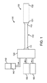
さらに、いくつかの実施形態においては、内管、及び冷凍アブレーション器具に送達される液状冷却剤を冷却する気体状冷却材は、液状冷却材とは異なる方向に流動する。つまり、自己冷却式供給又は拡張ホースは、液状冷却材とは異なる方向に流れる気体状冷却材を用いた対向流冷却又は対向流熱交換により冷却を行う。液状冷却材は、一方向、例えば冷却材の送達先であるアブレーション器具に向かう方向に流動し、液状冷却材を冷やす気体状冷却材は、管腔内において反対方向に流れ、供給ホースのアブレーション器具に連結しない側の端から排出されるように構成することができる。このような構成により、アブレーション器具に向かって内管内を流れている液状冷却材を冷やすと同時に、気体状冷却材を供給ホースの別の端から排出することができる。数々の実施形態に関しては、図1〜7Cを参照して以下に説明する。 複数の図における同じ符号は、同じ構成要素を表す。図1に示されるように、本発明の一実施形態による冷凍アブレーションシステム100は、自己冷却式の供給具又は拡張ホース又はコンジット110(供給ホース110と呼ぶ)を備える。供給ホース110の基端111はインターフェイス又は小型の極低温コンソール120(コンソール120と呼ぶ)に対応して、動作可能に連結、即ち接続される。供給ホース110の先端112は、冷凍アブレーション器具130の基端131に対応して、動作可能に連結、即ち接続される。アブレーション器具130の先端132は、タンク又は他の貯蔵槽140から供給される極低温流体142を用いて、例えば、心内膜組織等の心臓組織を含む組織を極低温で除去する。バルーン内圧力源、ポンプ、管、管腔、又はライン150がアブレーション器具130の排出圧を制御する。使用済みの極低温流体又は極低温物質は、カテーテル排出ポート、管、管腔、又はライン160を介してアブレーション器具130から排出される。
Further, in some embodiments, the gaseous coolant that cools the inner tube and the liquid coolant delivered to the cryoablation device flows in a different direction than the liquid coolant. That is, the self-cooling supply or expansion hose performs cooling by counterflow cooling or counterflow heat exchange using a gaseous coolant that flows in a direction different from the liquid coolant. The liquid coolant flows in one direction, eg, toward the ablation device to which the coolant is delivered, and the gaseous coolant that cools the liquid coolant flows in the opposite direction within the lumen, and the ablation device of the supply hose It can comprise so that it may discharge | emit from the end of the side which is not connected to. With such a configuration, the liquid coolant flowing in the inner tube toward the ablation device can be cooled, and at the same time, the gaseous coolant can be discharged from the other end of the supply hose. A number of embodiments are described below with reference to FIGS. The same reference numerals in the drawings represent the same components. As shown in FIG. 1, a
一実施形態においては、極低温流体142は亜酸化窒素(N2O)等の常温で流動可能な液状冷却材であり、システム100は心房細動を治療するために心内膜に極低温アブレーションを施す。しかし、別の実施形態においては、他の極低温冷却材又は流体142を用いてもよいし、他の症状や疾病を治療するために他の種類の組織に極低温アブレーションを施すために用いてもよい。説明の便宜上、ここでは心房細動を治療するために心内膜に極低温アブレーションを施す亜酸化窒素等の極低温流体又は液状冷却材142に関して述べる。
In one embodiment,
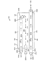
図2Aに示されるように、一実施形態による自己冷却式の供給又は拡張ホース110は外側部材又は管200を有する。管200は、シース202を含むか、又はシース202により形成される。シース202は、例えば断熱シースや熱交換シースであってよく、内部スペース又は管腔204(管腔204と呼ぶ)を形成する。外側部材200は、適宜な可撓性材料から形成可能であり、熱交換シース202は例えば高圧強化極低温管で形成可能である。ホース110の長さは、約1〜10フィート(約30.5cm〜3.5m)であり、例えば約6フィート(約1m82.9cm)である。ホースの幅は、約0.125〜2インチ(約0.3〜5.1cm)であり、例えば0.5インチ(約1.3cm)である。ホース110は、冷凍アブレーション器具130の基端131に連結される。冷凍アブレーション器具130の長さは約1〜6フィート(約30.5cm〜1m82.9cm)であり、例えば約3フィート(約91.4cm)であり、直径は、約0.05〜0.5インチ(約0.1〜1.3cm)であり、例えば約0.1インチ(約0.3cm)である。
As shown in FIG. 2A, a self-cooling supply or
図2Aに示す実施形態においては、外側部材200は、管腔204内に配置される複数の内管を有する。供給ホース200は、第1の内管220a及び第2の内管220bを有する。これらの内管220a及び220bはそれぞれ液状の冷却材142が流れる管腔223a及び223bを形成し、例えば、適宜の熱伝達特性を有する高圧極低温管であってよい。内管220a及び220bに液状冷却材142を供給する供給源即ちタンク140は同一のものであってもよいし、それぞれ別のものであってもよい。他の実施形態においては、内管220aを流れる液状冷却材142と内管220bを流れる液状冷却材142は異なるものである。説明の便宜上、1つの供給タンク140から両方の内管220a及び220bに液状冷却材142が供給され、内管220a及び220bの管腔223a及び223bに同種の液状冷却材142が流れる場合に関して述べるが、本発明の実施形態はこれに限定されるものではない。
In the embodiment shown in FIG. 2A, the
カテーテル供給管と称する第1の内管220aは、液状冷却材142の供給源140と冷凍アブレーション器具130の間に連結、即ち連通される。一実施形態においては、第1の内管220aの長さは約1〜10フィート(約30.5cm〜3.5m)であり、例えば約6フィート(約1m82.9cm)である。幅は、約0.01〜0.25インチ(約0.25〜6.35mm)であり、例えば約0.05インチ(約1.27mm)である。第1の内管220aを流れる液状冷却材142は心内膜の極低温アブレーションを行うために冷凍アブレーション器具130に提供される。例えば、第1の内管220aの基端221aは、小型コンソール120を介して極低温流体供給源140に連結され、第1の内管220aの先端222aは、冷凍アブレーション器具130の基端131に連結又は連係される。第1の内管220aの外面は、外側部材200の基端111及び先端112に水密性を有するようシールされる。
A first
図2Aの実施形態においては、第1の内管220aは供給ホース10の全長(供給ホース100の基端111から先端112まで)を貫通して延びるため、基端221aと先端222aのどちらも供給ホース110の内部で終端しないが、本発明の実施形態はこれに限定されない。
In the embodiment of FIG. 2A, since the first
図2Aに示す実施形態においては、冷却用冷却材供給管とも呼ばれる第2の内管220bは、第1の内管220aのように冷凍アブレーション器具130に液状冷却材142を供給しない。一実施形態においては、第2の内管220bの長さは約1〜10フィート(約30.5cm〜3.5m)であり、例えば約6フィート(約1m82.9cm)である。幅は、約0.01〜0.25インチ(約0.25〜6.35mm)であり、例えば約0.05インチ(約1.27mm)である。図2Aの実施形態においては、第2の内管220bは供給ホース110の全長にわたって延設されない。第2の内管220bの基端221bは供給ホース110の外側に延び外側部材200の基端111に流体気密性を有するようシールされて、流体供給源140及びコンソール120に対して連通されるが(前述の第1の内管220aと同様)、第2の内管220bの先端222bは、外側部材200の管腔204内で終端している。図2Bに示すように、別の実施形態においては、第2の内管220bを外側部材200の外に配置し、第2の内管220bの先端222bが外側部材200の管腔204内で終端するよう配置又は連結してもよい。
In the embodiment shown in FIG. 2A, the second
つまり、図2A及び図2Bに示すように、第2の内管220bは、外側部材200の大部分を通るよう延設してもよいし(図2A)、外側部材200の小部分のみを通るよう延設してよい(図2B)。さらに、図2A及び図2Bに示すように、第2の内管220bから放出された冷却材230は、外側部材200内で異なる方向に流動してもよいし(図2A)、一方向又はほぼ同一方向に流動してもよい(図2B)。
That is, as shown in FIGS. 2A and 2B, the second
このような構成と内管220a及び220bの配置とにより、第2の内管220bの管腔223bを流れる液状冷却材142は、第2の内管220bの先端開口部224bから外側部材200の管腔204内に放出される。放出された冷却材142は、外側部材200内を流動する気体230に気化する。この気体230が、第1の内管220a及び第1の内管220aに搬送される液状冷却材142を冷やす。例えば、高圧液状冷却材の温度は、大気温度での飽和温度に近くなる程度に冷却される。亜酸化窒素では、この温度は約−80度である。他の実施形態も同様に実施可能であるが、ここでは説明の便宜上、図2Aに示す装置構成に関して述べる。
With such a configuration and the arrangement of the
図2Aの実施形態においては、気体状の冷却材230が、第1の内管220aの一側のみ、ここでは第1の内管220aの上側に沿ってのみ流動している。しかし、使用時には、気体状の冷却材230は第1の内管220aの他の側又は面に沿って、又はこれらの側又は面上を流動してよく、例えば、第1の内管220aの全周囲において流動してもよい。つまり、図2Aは、気体状冷却材230の第1の内管220aに沿った流動を例示的に示すものである。第2の内管221aはらせん状に巻かれたフィラメント、管、又は他の好適な構造(図2A及び2Bには図示しない)を備えることができ、これにより、気体状冷却材230が第1の内管220aの近くを通過又は流動することができるとともに、第1の内管220aの外側部材200の内面への接触が防止可能となる。その結果、冷却効果及び保冷が強化される。
In the embodiment of FIG. 2A, the
このような対向流の冷却又は熱交換構成においては、内部で生成された気体状冷却材230を用いて供給ホース110内で液状冷却材142を冷やすことができ、よって、自己冷却式の供給ホース110が提供可能となる。第1の内管220aを流れる冷却された液状冷却材142は、内部で生成された気体状冷却材230に冷却されることにより、所望の温度及び圧力で冷凍アブレーション器具130に送達される。ここでは、ある種のコンソール120が必要であるとは思われるが、従来のシステムのコンソールのような大型で扱いにくいものでなくてもよい。さらに、いくつの実施形態においては、コンソール120が、従来の大型のコンソールのように独立冷却機、圧縮機、又は加圧機を備えていなくてもよい。つまり、追加の液状冷却材142を用いて自己冷却を行うことにより、コンソール120の占有面積及び部品を減らすことができる。そして、冷却機を有しない携帯型や使い捨て型のコンソール120等の非常に小型のコンソールを代わりに用いることができる。同時に、より低温の冷却材142を冷凍アブレーション器具130に提供することができ、組織の冷凍アブレーションを効率的に実施可能となる。
In such a counter-flow cooling or heat exchange configuration, the
図2Aに示す実施形態においては、内管220a及び内管220aに搬送される冷却材142の自己冷却は、対向流によりもたらされている。つまり、第1の内管220aと第2の内管220b内を流れる液状冷却材142はほぼ同一方向に流れるが、外側部材200内を流れる気体状冷却材230は別の方向に流れて、第1の内管220a、及び冷凍アブレーション器具130に提供される液状冷却材142を冷却する。図2Aの実施形態においては、第1の内管220aと第2の内管220bは互いにほぼ平行しており(構成が異なる場合があるが)、液状冷却材142は、供給管110の先端112及び冷凍アブレーション器具130に向かう第1の方向で流動する。一方、気体状冷却材230は反対方向、即ち供給管110の基端111に向かう方向に流動し、排出ポート又は管240から排出される。他の実施形態においては、液状冷却材142と気体状冷却材230は別の方向に流れるが、反対方向に流れていなくともよい。また、図2Aの実施形態においては、排出ポート又は管240が外側部材200の基端111を通って形成又は延設されるが、他の実施形態においては、例えば外側部材110内における内管220の数量や配向に応じて、外側部材200の別のセクションを通って形成されてもよい。
In the embodiment shown in FIG. 2A, the self-cooling of the
また、対向流の熱交換又は冷却による自己冷却の度合いは、内管220a及び220bを、例えば図2A及び2Bに示すように、異なる位置又は構成に配置することにより調整できる。さらに、図2Aにおいては、第2の内管220bの先端222bが外側部材200aの先端又は先端側の壁112の近く即ち隣に配置されるため、第2の内管220bから放出される気体状冷却材230は外側の管腔204内の大部分を通って流動し、第1の内管220の外面の大部分に接触する。さらに冷却の度合いを高めたい場合は、第2の内管220bを、外側管110の先端112及び第1の内管220aのさらに近くに配置するとよい。また、第2の内管220bを流れる液状冷却材142の量を増やすことにより、生成される気体状冷却材230の量を増やして冷却を強くしてもよい。さらに、気体状冷却材230にさらされる、もしくは熱接触する部分の第1の内管220aの表面積を増やしてもよい。さらにまた、第1の内管220aが気体状冷却材230にさらされる、もしくは熱接触する頻度を上げてもよい。つまり、本発明の実施形態は、様々な自己冷却又は内部冷却要件を満たすべく、様々なシステムやアブレーション器具130の構成に応じて適宜に調整可能である。
Further, the degree of self-cooling due to heat exchange or cooling of the counter flow can be adjusted by arranging the
図3に示すように、他の実施形態によるシステム300は、自己冷却式供給ホース110(図1、2A及び2Bで示したもの等)、及びインターフェイス310を介して供給ホース110に連結又は連通する極低温バルーンカテーテル300である冷凍アブレーション器具130を備える。図3の実施形態においては、極低温バルーンカテーテル300は、バルーン部材330を含む膨張型の極低温バルーン端部を有する。さらに、インターフェイス310は、Y字型アダプタである。Y字アダプタの第1の部分315は、供給ホース110の先端112に連結し、Y字アダプタの第2の部分316は冷凍アブレーション器具130の基端131に連結する。Y字アダプタの第3の部分317においては、ガイドワイヤ管腔320が、極低温バルーンカテーテル300の患者への挿入及び配置を容易にする可動又は偏向可能な先端を有するガイドワイヤ322を収容している。
As shown in FIG. 3, a
図4(説明の便宜上ガイド管腔320及びワイヤ322が省略されている)に示すように、コンソール120は1つ又は複数のバルブ401a、401b(401と総称する)を含み、このバルブ401a、402bにより、供給タンク140から供給管110の内管220a、220bへの液状冷却材142の送達が制御できる。図4の実施形態においては、バルブ401bが開放されることにより液状冷却材142が第2の内管220bの管腔223b内を流れ、気体状冷却材230により第1の内管220aが冷却される。そして、バルブ401aが開放されると、気体状冷却材230に冷やされた液状冷却材142が第1の内管220aの管腔223a内を流れて極低温バルーンカテーテル300に送達される。図4に示す実施形態は、2つのバルブ401a、401b、及び第1の内管220aと第2の内管220bとに分かれる供給ライン141により構成されるが、別の構成のバルブ及び供給ラインを用いて供給ホース110に液状冷却材142を提供してもよい。
As shown in FIG. 4 (guide
再び図3に戻って説明するが、一実施形態においては、使用した冷却材を極低温バルーンカテーテルから排出させる排出管又は管腔160は、供給管110及びコンソール120を通って延びる。別の実施形態においては、図4に示すように、排出管又は管腔160が、供給管110は通るが、コンソール120は通らない。さらに別の実施形態においては、図5(ガイドワイヤ管腔320及びガイドワイヤ322は分かり易くするために省略されている)に示すように、排出管又は管腔160はインターフェイス310から延び、供給管110及びコンソール120のどちらも通らない。つまり、図3〜5に示すように、使用済み冷却材を極低温アブレーションカテーテル300から排出する方法は、様々であってよいし、システムの様々な構成要素を通るよう延設されてもよい。図6A〜7Cは、自己冷却式供給管110を備えたシステムの実施形態を示す。これら自己冷却式供給管110は内部生成された気体状冷却材230を用いて極低温アブレーションカテーテル300に提供される前の液状冷却材142を冷やすが、この気体状冷却材230は、液状冷却材とは異なる方向に流動する。
Returning again to FIG. 3, in one embodiment, a drain or
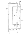
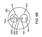
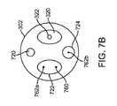
図6A〜6Dに示すように、本発明の他の実施形態によるシステム600は、自己冷却式の供給又は拡張ホース110、及びより大きい外側シース620内に配置される内側シース610を備える。この実施形態においては、バルーン内圧力管又はライン150及びカテーテル排出管又はライン160は、外側シース620を通って延びるシース610内に配置される。外側シース620は、シース610及び供給管110を収容する。第1の内管220a(カテーテル供給管)及び第2の内管220b(冷却用冷却材供給管)、気体状冷却材230を排出する排出ポート又は管240、バルーン内圧力管150、及びカテーテル排出管160は基端側コネクタ631に連結されて、コンソール120又は他のシステムコンポーネントとの連結又は連係が容易になっている。使用に適した基端コネクタ631の例としては、ラッチコネクタが挙げられる。同様に、先端側ホースコネクタ632を用いて、第1の内管220a(カテーテル供給管)、バルーン内圧力管150、及びカテーテル排出管160がインターフェイス310に連結されている。これにより、これらの管が極低温バルーンカテーテル300に連通される。ここでもラッチコネクタを用いることができる。基端側ホースコネクタ631及び先端側ホースコネクタ632は、誤って引っ張られた際の分離によるダメージからコネクタ631、632を守るべく、張力緩和ワイヤ633により連結されていてもよい。使用時には、第2の内管220b内を流れる液状冷却材142に由来する気体状液状冷却材230が第1の内管220aを冷やし、冷えた液状冷却材142が第1の内管220aから極低温バルーンカテーテルに提供される。そして、バルーン部材330が膨張し、バルーン部材330に近接する心臓組織に冷凍アブレーションが施される。使用済み冷却材は、排出ポート又は管240を介して極低温バルーンカテーテル300から排出される。
As shown in FIGS. 6A-6D, a
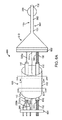
図7A〜7Cは、自己冷却式の供給又は拡張ホース110を含む別のシステム700を示し、冷凍アブレーションを行うために他のシステムコンポーネントをどのように動作可能に連結するかを示す。この実施形態においては、第1の内管220aは、カテーテル300内に進入するよう延びるか、極低温バルーンカテーテル300の本体302を通って延びる独立したカテーテル供給管又は管腔720に連結即ち連通される。これにより、第1の内管220a及び内部カテーテル供給管又は管腔720の少なくともいずれかにより、冷却された液状冷却材142が提供される。
7A-7C illustrate another
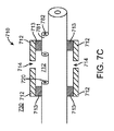
図7A〜7Cに示す実施形態において、長尺状の部材302又は押出成形品の先端部は、冷却材を分散させるために使用される分散部材即ちマニフォールド710を含む。分散部材710は長尺状本体302から延び、カテーテル供給管720の先端又は出口に連通する内部管腔又はスペース712を形成する。この実施形態においては、分散部材710は、長尺状本体301に密閉状態となるよう溶着713等により係合、即ち連結された分散要素712を含み、これにより、ノズル又は開口部714が形成される。冷却材は、このノズル又は開口部714を介して分散される。管状要素781の出口782は、閉塞即ち密閉されている。例えば、マニフォールド710の組み立て時に、シールが溶着713され、管状要素781に気体を流すことにより粒子が除去される。その後、管状要素781がシール782される。これにより、粒子によるノズル714の閉塞が防止即ち抑制される。
In the embodiment shown in FIGS. 7A-7C, the
図7A〜7Cに示す実施形態においては、バルーン330は内壁742を囲む外壁741を備え、これにより、バルーンの内壁742と外壁741の間の中間スペース743が形成される。バルーン330は、内壁742の内面により区画される内部チャンバ730を有する。冷却前の液状冷却材142が流れる供給管即ち管腔720の出口は、分散部材710の内部スペース712及び内部チャンバ730と連通している。カテーテル排出管即ち管腔160、より詳細に述べると長尺状本体302内に延設された他の管即ち管腔722は、内部チャンバ730と連通している。バルーン内圧力管即ち管腔150、又は本体302内に延設された管即ち管腔724は、バルーン370の壁741、742の間に形成された中間スペース743に連通している。
In the embodiment shown in FIGS. 7A-7C, the
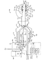
使用時には、1つ又は複数のバルブ750a〜750cが開放することにより供給タンク140から供給ホース110に液状冷却材142が流れる。液状冷却材142は供給ライン141を流れ、供給ライン141は、2つの異なる内側ライン即ち管220a、220b(図4と同様)に分割即ち分岐される。図示する実施形態においては、第1の内管220aを流れる液状冷却材142は、逆方向に流れる気体状冷却材230により冷却される。1つ又は複数の温度センサ即ち熱電対760a、760b(温度センサー760と総称する)を使用して、供給ホース110内の液状冷却材142の冷却効果を監視する。これは、コントローラ、マイクロプロセッサ、他の適切なハードウェア及びソフトウェア等、図7において770と付された機器を用いて行われる。冷却された液状の冷却材142は、第1の内管220a内及びカテーテルへの供給管即ち管腔720a内を流れ、分散部材710の内部スペース712内に放出される。
In use, the
冷却された液状冷却材142がスペース712に放出されることにより圧力が降下し、冷却された液状冷却材142が非常に低温の液体及び気体の噴霧に冷却される。液状冷却材142の圧力及び供給ライン720の寸法は、非常に低温の液状冷却材142がバルーン内壁742の内面に対して噴霧され、熱を吸収し急速に気化することにより、拡張式バルーンが膨張されるように設定される。アブレーション時には、バルーンの壁741、742は共に押されて、アブレーションが施される組織を押す。バルーン外壁741が、アブレーションが施される心臓組織に押し付けられた状態、又は組織内に位置した状態でバルーン壁741、742が急速に冷却されることにより、冷凍アブレーションが行われる。
As the cooled
使用済みの気体状冷却材は、管又は管腔722及び出口ポート又は管150から排出される。カテーテル300から排出される使用済み気体状冷却材の流動及び圧量は、冷却材流動センサ764、圧量センサ766、又は他の適切なデバイスにより監視可能である。さらに、1つ又は複数の流動センサ762a、762bをカテーテル排出管腔160及び/又はバルーン内圧力管腔150に配置して、カテーテル300内における導電性液(血液等)の有無を監視することもできる。これにより、コントローラ770や他の適切なコンポーネント等を用いたバルーン内圧力レベルの調整や、冷却材流動の停止が必要か否かを判断できる。
Spent gaseous coolant is discharged from the tube or
例えば、異なる症状や疾病の治療を目的として多種の組織にアブレーションを行うよう実施形態を構成してもよい。一例としては、前述した、心房性細動の治療のために心臓内アブレーションを行う実施形態が挙げられる。別の実施形態においては、オープンループ型、又はクローズループ型の流体供給カテーテルシステムのコンポーネントである冷凍アブレーション器具の液状冷却材が冷却される。 For example, embodiments may be configured to ablate various tissues for the purpose of treating different symptoms and diseases. An example is the embodiment described above for performing intracardiac ablation for the treatment of atrial fibrillation. In another embodiment, the liquid coolant of a cryoablation device that is a component of an open loop or closed loop fluid delivery catheter system is cooled.
さらに、本明細書に記載する実施形態は、内部で生成された気体状の亜酸化窒素を用いて液状の亜酸化窒素を冷却する自己冷却式の供給ホースに関するものであるが、他の実施形態においては、気体状亜酸化窒素を用いて異なる種類の液状冷却材又は冷媒が冷却され、気体状冷却材としては、気体状亜酸化窒素以外の気体状冷却材が使用される。また、使用する冷却材に応じて、冷却材は、気体及び液体の流動可能な混合物であってもよい。従って、冷却材が「液状」又は液体のような特性を有していたとしても、冷却材は、液体及び少量のガスの流動可能な混合物又は混合流体であってもよい。また、第1の内管内を流動して冷凍アブレーション器具に提供される冷却材を冷やすために用いられる第2の内管内を流動する冷却材は、同種の冷却材でもよいし、種類の異なる冷却材であってもよい。または同一の相(液体等)でもよいし、相が異なっていてもよい。 Further, the embodiments described herein relate to self-cooling supply hoses that cool gaseous nitrous oxide using internally generated gaseous nitrous oxide, while other embodiments are described. , Different types of liquid coolants or refrigerants are cooled using gaseous nitrous oxide, and gaseous coolants other than gaseous nitrous oxide are used as the gaseous coolant. Also, depending on the coolant used, the coolant may be a gas and liquid flowable mixture. Thus, even though the coolant has “liquid” or liquid-like properties, the coolant may be a flowable mixture or fluid of liquid and a small amount of gas. The coolant flowing in the second inner pipe used for cooling the coolant supplied to the refrigeration ablation instrument by flowing in the first inner pipe may be the same type of coolant or different types of cooling. It may be a material. Or the same phase (liquid etc.) may be sufficient and a phase may differ.
また、いくつか実施形態においては、供給ホースを単独で用いてもよいし(供給ホースは使い捨て型であってもよい)、供給ホースとカテーテルの組み合わせであってもよい(この組み合わせも使い捨て型であってもよい)。さらには、上記のシステムコンポーネントの組み合わせであってもよい。 In some embodiments, the supply hose may be used alone (the supply hose may be a disposable type) or a combination of a supply hose and a catheter (this combination is also a disposable type). May be). Further, it may be a combination of the above system components.
Claims (14)
少なくとも一部が外側部材の管腔内に位置するとともに、アブレーション器具に連通する冷却材送達用の管腔を有する第1の内管と、
第2の内管から放出される液状の冷却材が気化することにより形成された気体状の冷却材が外側部材の管腔内を流動して第1の内管により搬送される液状の冷却材を冷却すべく、外側部材の管腔内で終結する開口した先端部を有する第2の内管とを備える、冷凍アブレーション器具に送達される冷却材を冷却する装置。 An outer member having a proximal end and a distal end, forming a lumen extending between the proximal end and the distal end, the distal end coupled to the ablation instrument;
A first inner tube at least partially located within the lumen of the outer member and having a coolant delivery lumen in communication with the ablation device;
The liquid coolant formed by vaporizing the liquid coolant discharged from the second inner tube flows through the lumen of the outer member and is conveyed by the first inner tube. And a second inner tube having an open tip that terminates within the lumen of the outer member to cool the device.
冷凍アブレーション器具に連通し、冷凍アブレーション器具に冷却された液状の冷却材を提供するとともに請求項1に記載の装置を有するコンジットとを備える冷凍アブレーションシステム。 A cryoablation device that removes tissue at cryogenic temperatures;
A refrigeration ablation system comprising: a liquid coolant that is in communication with the refrigeration ablation instrument and that is cooled to the refrigeration ablation instrument and includes the conduit according to claim 1.
Applications Claiming Priority (3)
| Application Number | Priority Date | Filing Date | Title |
|---|---|---|---|
| US5259808P | 2008-05-12 | 2008-05-12 | |
| US61/052,598 | 2008-05-12 | ||
| PCT/US2009/042162 WO2009140066A1 (en) | 2008-05-12 | 2009-04-29 | Apparatus for chilling cryo-ablation coolant |
Publications (2)
| Publication Number | Publication Date |
|---|---|
| JP2011521679A true JP2011521679A (en) | 2011-07-28 |
| JP2011521679A5 JP2011521679A5 (en) | 2012-11-08 |
Family
ID=41010504
Family Applications (1)
| Application Number | Title | Priority Date | Filing Date |
|---|---|---|---|
| JP2011509543A Pending JP2011521679A (en) | 2008-05-12 | 2009-04-29 | Equipment for cooling the cryoablation coolant |
Country Status (4)
| Country | Link |
|---|---|
| US (2) | US9028445B2 (en) |
| EP (1) | EP2288306A1 (en) |
| JP (1) | JP2011521679A (en) |
| WO (1) | WO2009140066A1 (en) |
Cited By (2)
| Publication number | Priority date | Publication date | Assignee | Title |
|---|---|---|---|---|
| US9655668B2 (en) | 2008-05-12 | 2017-05-23 | Boston Scientific Scimed, Inc. | Apparatus and method for chilling cryo-ablation coolant and resulting cryo-ablation system |
| JP2019514463A (en) * | 2016-05-13 | 2019-06-06 | クライオセラピューティクス ゲーエムベーハー | Balloon catheter |
Families Citing this family (105)
| Publication number | Priority date | Publication date | Assignee | Title |
|---|---|---|---|---|
| EP3045136B1 (en) | 2003-09-12 | 2021-02-24 | Vessix Vascular, Inc. | Selectable eccentric remodeling and/or ablation of atherosclerotic material |
| US9713730B2 (en) | 2004-09-10 | 2017-07-25 | Boston Scientific Scimed, Inc. | Apparatus and method for treatment of in-stent restenosis |
| US8396548B2 (en) | 2008-11-14 | 2013-03-12 | Vessix Vascular, Inc. | Selective drug delivery in a lumen |
| US8920414B2 (en) | 2004-09-10 | 2014-12-30 | Vessix Vascular, Inc. | Tuned RF energy and electrical tissue characterization for selective treatment of target tissues |
| US8019435B2 (en) | 2006-05-02 | 2011-09-13 | Boston Scientific Scimed, Inc. | Control of arterial smooth muscle tone |
| AU2007310991B2 (en) | 2006-10-18 | 2013-06-20 | Boston Scientific Scimed, Inc. | System for inducing desirable temperature effects on body tissue |
| ES2560006T3 (en) | 2006-10-18 | 2016-02-17 | Vessix Vascular, Inc. | Induction of desirable temperature effects on body tissue |
| US8439905B2 (en) * | 2008-09-19 | 2013-05-14 | Endocare, Inc. | Nucleation enhanced surface modification to support physical vapor deposition to create a vacuum |
| US9089316B2 (en) | 2009-11-02 | 2015-07-28 | Endocare, Inc. | Cryogenic medical system |
| US10182859B2 (en) * | 2008-09-03 | 2019-01-22 | Endocare, Inc. | Medical device for the transport of subcooled cryogenic fluid through a linear heat exchanger |
| US9408654B2 (en) | 2008-09-03 | 2016-08-09 | Endocare, Inc. | Modular pulsed pressure device for the transport of liquid cryogen to a cryoprobe |
| WO2010028409A1 (en) * | 2008-09-03 | 2010-03-11 | Dobson, Melissa, K. | A cryogenic system and method of use |
| US10695126B2 (en) | 2008-10-06 | 2020-06-30 | Santa Anna Tech Llc | Catheter with a double balloon structure to generate and apply a heated ablative zone to tissue |
| WO2010056745A1 (en) | 2008-11-17 | 2010-05-20 | Minnow Medical, Inc. | Selective accumulation of energy with or without knowledge of tissue topography |
| US20110270238A1 (en) | 2009-12-31 | 2011-11-03 | Raed Rizq | Compliant Cryoballoon Apparatus for Denervating Ostia of the Renal Arteries |
| US20110263921A1 (en) | 2009-12-31 | 2011-10-27 | Anthony Vrba | Patterned Denervation Therapy for Innervated Renal Vasculature |
| US9089314B2 (en) * | 2010-01-27 | 2015-07-28 | Medtronic Cryocath Lp | Partially compliant balloon device |
| CA2795229A1 (en) | 2010-04-09 | 2011-10-13 | Vessix Vascular, Inc. | Power generating and control apparatus for the treatment of tissue |
| US9192790B2 (en) | 2010-04-14 | 2015-11-24 | Boston Scientific Scimed, Inc. | Focused ultrasonic renal denervation |
| US8473067B2 (en) | 2010-06-11 | 2013-06-25 | Boston Scientific Scimed, Inc. | Renal denervation and stimulation employing wireless vascular energy transfer arrangement |
| US9155589B2 (en) | 2010-07-30 | 2015-10-13 | Boston Scientific Scimed, Inc. | Sequential activation RF electrode set for renal nerve ablation |
| US9358365B2 (en) | 2010-07-30 | 2016-06-07 | Boston Scientific Scimed, Inc. | Precision electrode movement control for renal nerve ablation |
| US9084609B2 (en) | 2010-07-30 | 2015-07-21 | Boston Scientific Scime, Inc. | Spiral balloon catheter for renal nerve ablation |
| US9408661B2 (en) | 2010-07-30 | 2016-08-09 | Patrick A. Haverkost | RF electrodes on multiple flexible wires for renal nerve ablation |
| US9463062B2 (en) | 2010-07-30 | 2016-10-11 | Boston Scientific Scimed, Inc. | Cooled conductive balloon RF catheter for renal nerve ablation |
| US20120029512A1 (en) | 2010-07-30 | 2012-02-02 | Willard Martin R | Balloon with surface electrodes and integral cooling for renal nerve ablation |
| EP2600784B1 (en) | 2010-08-05 | 2021-12-29 | Medtronic Ireland Manufacturing Unlimited Company | Cryoablation apparatuses, systems, and methods for renal neuromodulation |
| US8974451B2 (en) | 2010-10-25 | 2015-03-10 | Boston Scientific Scimed, Inc. | Renal nerve ablation using conductive fluid jet and RF energy |
| US20120143294A1 (en) | 2010-10-26 | 2012-06-07 | Medtronic Adrian Luxembourg S.a.r.l. | Neuromodulation cryotherapeutic devices and associated systems and methods |
| US9060754B2 (en) | 2010-10-26 | 2015-06-23 | Medtronic Ardian Luxembourg S.A.R.L. | Neuromodulation cryotherapeutic devices and associated systems and methods |
| US9220558B2 (en) | 2010-10-27 | 2015-12-29 | Boston Scientific Scimed, Inc. | RF renal denervation catheter with multiple independent electrodes |
| US9028485B2 (en) | 2010-11-15 | 2015-05-12 | Boston Scientific Scimed, Inc. | Self-expanding cooling electrode for renal nerve ablation |
| US9089350B2 (en) | 2010-11-16 | 2015-07-28 | Boston Scientific Scimed, Inc. | Renal denervation catheter with RF electrode and integral contrast dye injection arrangement |
| US9668811B2 (en) | 2010-11-16 | 2017-06-06 | Boston Scientific Scimed, Inc. | Minimally invasive access for renal nerve ablation |
| US9326751B2 (en) | 2010-11-17 | 2016-05-03 | Boston Scientific Scimed, Inc. | Catheter guidance of external energy for renal denervation |
| US9060761B2 (en) | 2010-11-18 | 2015-06-23 | Boston Scientific Scime, Inc. | Catheter-focused magnetic field induced renal nerve ablation |
| US9192435B2 (en) | 2010-11-22 | 2015-11-24 | Boston Scientific Scimed, Inc. | Renal denervation catheter with cooled RF electrode |
| US9023034B2 (en) | 2010-11-22 | 2015-05-05 | Boston Scientific Scimed, Inc. | Renal ablation electrode with force-activatable conduction apparatus |
| US20120157993A1 (en) | 2010-12-15 | 2012-06-21 | Jenson Mark L | Bipolar Off-Wall Electrode Device for Renal Nerve Ablation |
| WO2012100095A1 (en) | 2011-01-19 | 2012-07-26 | Boston Scientific Scimed, Inc. | Guide-compatible large-electrode catheter for renal nerve ablation with reduced arterial injury |
| EP3590453B1 (en) | 2011-02-01 | 2024-02-28 | Channel Medsystems, Inc. | Apparatus for cryogenic treatment of a body cavity or lumen |
| EP2701623B1 (en) | 2011-04-25 | 2016-08-17 | Medtronic Ardian Luxembourg S.à.r.l. | Apparatus related to constrained deployment of cryogenic balloons for limited cryogenic ablation of vessel walls |
| CN103813745B (en) | 2011-07-20 | 2016-06-29 | 波士顿科学西美德公司 | In order to visualize, be directed at and to melt transcutaneous device and the method for nerve |
| WO2013016203A1 (en) | 2011-07-22 | 2013-01-31 | Boston Scientific Scimed, Inc. | Nerve modulation system with a nerve modulation element positionable in a helical guide |
| WO2013055826A1 (en) | 2011-10-10 | 2013-04-18 | Boston Scientific Scimed, Inc. | Medical devices including ablation electrodes |
| US9420955B2 (en) | 2011-10-11 | 2016-08-23 | Boston Scientific Scimed, Inc. | Intravascular temperature monitoring system and method |
| EP2765940B1 (en) | 2011-10-11 | 2015-08-26 | Boston Scientific Scimed, Inc. | Off-wall electrode device for nerve modulation |
| US9364284B2 (en) | 2011-10-12 | 2016-06-14 | Boston Scientific Scimed, Inc. | Method of making an off-wall spacer cage |
| WO2013059202A1 (en) | 2011-10-18 | 2013-04-25 | Boston Scientific Scimed, Inc. | Integrated crossing balloon catheter |
| US9162046B2 (en) | 2011-10-18 | 2015-10-20 | Boston Scientific Scimed, Inc. | Deflectable medical devices |
| WO2013067421A2 (en) * | 2011-11-05 | 2013-05-10 | Medtronic Ardian Luxembourg S.A.R.L. | Systems, devices and methods for crynogenic renal neuromodulation |
| CN104023662B (en) | 2011-11-08 | 2018-02-09 | 波士顿科学西美德公司 | Hole portion renal nerve melts |
| WO2013074813A1 (en) | 2011-11-15 | 2013-05-23 | Boston Scientific Scimed, Inc. | Device and methods for renal nerve modulation monitoring |
| US9119632B2 (en) | 2011-11-21 | 2015-09-01 | Boston Scientific Scimed, Inc. | Deflectable renal nerve ablation catheter |
| US9265969B2 (en) | 2011-12-21 | 2016-02-23 | Cardiac Pacemakers, Inc. | Methods for modulating cell function |
| US9174050B2 (en) | 2011-12-23 | 2015-11-03 | Vessix Vascular, Inc. | Methods and apparatuses for remodeling tissue of or adjacent to a body passage |
| EP2797534A1 (en) | 2011-12-28 | 2014-11-05 | Boston Scientific Scimed, Inc. | Device and methods for nerve modulation using a novel ablation catheter with polymeric ablative elements |
| US9050106B2 (en) | 2011-12-29 | 2015-06-09 | Boston Scientific Scimed, Inc. | Off-wall electrode device and methods for nerve modulation |
| WO2013162700A1 (en) | 2012-04-27 | 2013-10-31 | Medtronic Ardian Luxembourg Sarl | Cryotherapeutic devices for renal neuromodulation and associated systems and methods |
| US9241752B2 (en) | 2012-04-27 | 2016-01-26 | Medtronic Ardian Luxembourg S.A.R.L. | Shafts with pressure relief in cryotherapeutic catheters and associated devices, systems, and methods |
| WO2013169927A1 (en) | 2012-05-08 | 2013-11-14 | Boston Scientific Scimed, Inc. | Renal nerve modulation devices |
| CN104540465A (en) | 2012-08-24 | 2015-04-22 | 波士顿科学西美德公司 | Intravascular catheter with a balloon comprising separate microporous regions |
| WO2014043687A2 (en) | 2012-09-17 | 2014-03-20 | Boston Scientific Scimed, Inc. | Self-positioning electrode system and method for renal nerve modulation |
| US10398464B2 (en) | 2012-09-21 | 2019-09-03 | Boston Scientific Scimed, Inc. | System for nerve modulation and innocuous thermal gradient nerve block |
| WO2014047454A2 (en) | 2012-09-21 | 2014-03-27 | Boston Scientific Scimed, Inc. | Self-cooling ultrasound ablation catheter |
| US10835305B2 (en) | 2012-10-10 | 2020-11-17 | Boston Scientific Scimed, Inc. | Renal nerve modulation devices and methods |
| US9095321B2 (en) | 2012-11-21 | 2015-08-04 | Medtronic Ardian Luxembourg S.A.R.L. | Cryotherapeutic devices having integral multi-helical balloons and methods of making the same |
| US9017317B2 (en) | 2012-12-06 | 2015-04-28 | Medtronic Ardian Luxembourg S.A.R.L. | Refrigerant supply system for cryotherapy including refrigerant recompression and associated devices, systems, and methods |
| US9693821B2 (en) | 2013-03-11 | 2017-07-04 | Boston Scientific Scimed, Inc. | Medical devices for modulating nerves |
| US9956033B2 (en) | 2013-03-11 | 2018-05-01 | Boston Scientific Scimed, Inc. | Medical devices for modulating nerves |
| US9808311B2 (en) | 2013-03-13 | 2017-11-07 | Boston Scientific Scimed, Inc. | Deflectable medical devices |
| JP6220044B2 (en) | 2013-03-15 | 2017-10-25 | ボストン サイエンティフィック サイムド,インコーポレイテッドBoston Scientific Scimed,Inc. | Medical device for renal nerve ablation |
| US10265122B2 (en) | 2013-03-15 | 2019-04-23 | Boston Scientific Scimed, Inc. | Nerve ablation devices and related methods of use |
| JP6139772B2 (en) | 2013-03-15 | 2017-05-31 | ボストン サイエンティフィック サイムド,インコーポレイテッドBoston Scientific Scimed,Inc. | Control unit for use with electrode pads and method for estimating leakage |
| WO2014205399A1 (en) | 2013-06-21 | 2014-12-24 | Boston Scientific Scimed, Inc. | Medical devices for renal nerve ablation having rotatable shafts |
| CN105473091B (en) | 2013-06-21 | 2020-01-21 | 波士顿科学国际有限公司 | Renal denervation balloon catheter with co-movable electrode supports |
| US9707036B2 (en) | 2013-06-25 | 2017-07-18 | Boston Scientific Scimed, Inc. | Devices and methods for nerve modulation using localized indifferent electrodes |
| JP6204579B2 (en) | 2013-07-01 | 2017-09-27 | ボストン サイエンティフィック サイムド,インコーポレイテッドBoston Scientific Scimed,Inc. | Renal nerve ablation medical device |
| CN105377169B (en) | 2013-07-11 | 2019-04-19 | 波士顿科学国际有限公司 | Device and method for neuromodulation |
| EP3019106A1 (en) | 2013-07-11 | 2016-05-18 | Boston Scientific Scimed, Inc. | Medical device with stretchable electrode assemblies |
| WO2015010074A1 (en) | 2013-07-19 | 2015-01-22 | Boston Scientific Scimed, Inc. | Spiral bipolar electrode renal denervation balloon |
| CN105392435B (en) | 2013-07-22 | 2018-11-09 | 波士顿科学国际有限公司 | Renal nerve ablation catheter with twisting sacculus |
| US10342609B2 (en) | 2013-07-22 | 2019-07-09 | Boston Scientific Scimed, Inc. | Medical devices for renal nerve ablation |
| CN105473093B (en) | 2013-08-22 | 2019-02-05 | 波士顿科学国际有限公司 | Flexible circuit with the improved adhesion strength to renal nerve modulation sacculus |
| CN105555218B (en) | 2013-09-04 | 2019-01-15 | 波士顿科学国际有限公司 | With radio frequency (RF) foley's tube rinsed with cooling capacity |
| EP3043733A1 (en) | 2013-09-13 | 2016-07-20 | Boston Scientific Scimed, Inc. | Ablation balloon with vapor deposited cover layer |
| US11246654B2 (en) | 2013-10-14 | 2022-02-15 | Boston Scientific Scimed, Inc. | Flexible renal nerve ablation devices and related methods of use and manufacture |
| WO2015057521A1 (en) | 2013-10-14 | 2015-04-23 | Boston Scientific Scimed, Inc. | High resolution cardiac mapping electrode array catheter |
| JP6259098B2 (en) | 2013-10-15 | 2018-01-10 | ボストン サイエンティフィック サイムド,インコーポレイテッドBoston Scientific Scimed,Inc. | Medical device and method for manufacturing the medical device |
| US9770606B2 (en) | 2013-10-15 | 2017-09-26 | Boston Scientific Scimed, Inc. | Ultrasound ablation catheter with cooling infusion and centering basket |
| EP3057521B1 (en) | 2013-10-18 | 2020-03-25 | Boston Scientific Scimed, Inc. | Balloon catheters with flexible conducting wires |
| WO2015061457A1 (en) | 2013-10-25 | 2015-04-30 | Boston Scientific Scimed, Inc. | Embedded thermocouple in denervation flex circuit |
| CN105899157B (en) | 2014-01-06 | 2019-08-09 | 波士顿科学国际有限公司 | Tear-proof flexible circuit assembly |
| WO2015119890A1 (en) | 2014-02-04 | 2015-08-13 | Boston Scientific Scimed, Inc. | Alternative placement of thermal sensors on bipolar electrode |
| US11000679B2 (en) | 2014-02-04 | 2021-05-11 | Boston Scientific Scimed, Inc. | Balloon protection and rewrapping devices and related methods of use |
| US10492842B2 (en) | 2014-03-07 | 2019-12-03 | Medtronic Ardian Luxembourg S.A.R.L. | Monitoring and controlling internally administered cryotherapy |
| CA2896195A1 (en) * | 2014-07-22 | 2016-01-22 | Biosense Webster (Israel) Ltd. | Catheter with multiple irrigated electrodes and a force sensor |
| US11331140B2 (en) | 2016-05-19 | 2022-05-17 | Aqua Heart, Inc. | Heated vapor ablation systems and methods for treating cardiac conditions |
| US20180242821A1 (en) * | 2017-02-28 | 2018-08-30 | Biosense Webster (Israel) Ltd. | Lens in balloon catheter |
| US11179185B2 (en) | 2018-07-20 | 2021-11-23 | Atricure, Inc. | Cryogenic surgical systems |
| CN109480999B (en) * | 2018-12-19 | 2024-01-05 | 康沣生物科技(上海)股份有限公司 | Double-stage cryoablation system |
| CN115670632A (en) * | 2019-12-04 | 2023-02-03 | 海杰亚(北京)医疗器械有限公司 | High-low temperature composite ablation operation system |
| EP3988042B1 (en) | 2020-06-09 | 2023-06-21 | Accu Target Medipharma (Shanghai) Co., Ltd. | Double-layer freezing expansion balloon |
| WO2023006509A1 (en) * | 2021-07-29 | 2023-02-02 | Medtronic Ireland Manufacturing Unlimited Company | Manifold for cryogenic balloon catheter |
| CN113425402B (en) * | 2021-08-27 | 2021-12-17 | 上海安钛克医疗科技有限公司 | Catheter capable of judging balloon adhesion and ablation system |
Citations (5)
| Publication number | Priority date | Publication date | Assignee | Title |
|---|---|---|---|---|
| JPH07155334A (en) * | 1993-10-26 | 1995-06-20 | Cordis Europ Nv | Catheter for freeze resecting operation |
| EP1129670A1 (en) * | 2000-03-02 | 2001-09-05 | Biosense Webster, Inc. | Cryoablation catheter for long lesion ablations |
| JP2003503123A (en) * | 1999-06-25 | 2003-01-28 | クライオジェン インコーポレイテッド | Pre-cooled cryogenic ablation system |
| JP2004505664A (en) * | 2000-08-09 | 2004-02-26 | クライオジェン インコーポレイテッド | Control system for cryogenic surgery |
| JP2005503241A (en) * | 2001-09-27 | 2005-02-03 | ガリル メディカル リミテッド | Cryoplasty apparatus and method |
Family Cites Families (26)
| Publication number | Priority date | Publication date | Assignee | Title |
|---|---|---|---|---|
| US5147355A (en) | 1988-09-23 | 1992-09-15 | Brigham And Womens Hospital | Cryoablation catheter and method of performing cryoablation |
| ZA917281B (en) | 1990-09-26 | 1992-08-26 | Cryomedical Sciences Inc | Cryosurgical instrument and system and method of cryosurgery |
| US5254116A (en) | 1991-09-06 | 1993-10-19 | Cryomedical Sciences, Inc. | Cryosurgical instrument with vent holes and method using same |
| GB2283678B (en) | 1993-11-09 | 1998-06-03 | Spembly Medical Ltd | Cryosurgical catheter probe |
| US6602247B2 (en) | 1997-02-27 | 2003-08-05 | Cryocath Technologies Inc. | Apparatus and method for performing a treatment on a selected tissue region |
| US6235019B1 (en) | 1997-02-27 | 2001-05-22 | Cryocath Technologies, Inc. | Cryosurgical catheter |
| US5868735A (en) * | 1997-03-06 | 1999-02-09 | Scimed Life Systems, Inc. | Cryoplasty device and method |
| US7025762B2 (en) | 1997-05-23 | 2006-04-11 | Crymed Technologies, Inc. | Method and apparatus for cryogenic spray ablation of gastrointestinal mucosa |
| US6027499A (en) | 1997-05-23 | 2000-02-22 | Fiber-Tech Medical, Inc. (Assignee Of Jennifer B. Cartledge) | Method and apparatus for cryogenic spray ablation of gastrointestinal mucosa |
| US6379378B1 (en) * | 2000-03-03 | 2002-04-30 | Innercool Therapies, Inc. | Lumen design for catheter |
| US6106518A (en) | 1998-04-09 | 2000-08-22 | Cryocath Technologies, Inc. | Variable geometry tip for a cryosurgical ablation device |
| US20050228367A1 (en) | 1999-01-25 | 2005-10-13 | Marwan Abboud | Leak detection system for catheter based medical device |
| US6592577B2 (en) | 1999-01-25 | 2003-07-15 | Cryocath Technologies Inc. | Cooling system |
| US6569158B1 (en) | 1999-01-25 | 2003-05-27 | Cryocath Technologies, Inc. | Leak detection system |
| EP1158906B1 (en) | 1999-02-10 | 2008-08-13 | Swaminathan Jayaraman | Balloon catheter for cryotherapy |
| US6468297B1 (en) | 1999-02-24 | 2002-10-22 | Cryovascular Systems, Inc. | Cryogenically enhanced intravascular interventions |
| US6231543B1 (en) | 1999-04-15 | 2001-05-15 | Intella Interventional Systems, Inc. | Single lumen balloon catheter |
| US6280439B1 (en) | 1999-07-12 | 2001-08-28 | Cryocath Technologies, Inc. | Adjustable position injection tubing |
| WO2002001123A1 (en) | 2000-06-23 | 2002-01-03 | Mmr Technologies, Inc. | Flexible counter-flow heat exchangers |
| FR2811015B1 (en) | 2000-06-30 | 2003-02-21 | Ecia Equip Composants Ind Auto | EXHAUST VOLUME AND EXHAUST DEVICE COMPRISING SAME |
| US6706037B2 (en) | 2000-10-24 | 2004-03-16 | Galil Medical Ltd. | Multiple cryoprobe apparatus and method |
| US6755823B2 (en) | 2001-02-28 | 2004-06-29 | Cryocath Technologies Inc. | Medical device with enhanced cooling power |
| US7150745B2 (en) | 2004-01-09 | 2006-12-19 | Barrx Medical, Inc. | Devices and methods for treatment of luminal tissue |
| US7727228B2 (en) | 2004-03-23 | 2010-06-01 | Medtronic Cryocath Lp | Method and apparatus for inflating and deflating balloon catheters |
| US8177779B2 (en) | 2004-06-02 | 2012-05-15 | Boston Scientific Scimed, Inc. | Controllable pressure cryogenic balloon treatment system and method |
| WO2009140066A1 (en) | 2008-05-12 | 2009-11-19 | Boston Scientific Scimed, Inc. | Apparatus for chilling cryo-ablation coolant |
-
2009
- 2009-04-29 WO PCT/US2009/042162 patent/WO2009140066A1/en active Application Filing
- 2009-04-29 US US12/432,465 patent/US9028445B2/en active Active
- 2009-04-29 EP EP09747152A patent/EP2288306A1/en not_active Withdrawn
- 2009-04-29 JP JP2011509543A patent/JP2011521679A/en active Pending
-
2015
- 2015-05-12 US US14/710,288 patent/US9655668B2/en active Active
Patent Citations (5)
| Publication number | Priority date | Publication date | Assignee | Title |
|---|---|---|---|---|
| JPH07155334A (en) * | 1993-10-26 | 1995-06-20 | Cordis Europ Nv | Catheter for freeze resecting operation |
| JP2003503123A (en) * | 1999-06-25 | 2003-01-28 | クライオジェン インコーポレイテッド | Pre-cooled cryogenic ablation system |
| EP1129670A1 (en) * | 2000-03-02 | 2001-09-05 | Biosense Webster, Inc. | Cryoablation catheter for long lesion ablations |
| JP2004505664A (en) * | 2000-08-09 | 2004-02-26 | クライオジェン インコーポレイテッド | Control system for cryogenic surgery |
| JP2005503241A (en) * | 2001-09-27 | 2005-02-03 | ガリル メディカル リミテッド | Cryoplasty apparatus and method |
Cited By (2)
| Publication number | Priority date | Publication date | Assignee | Title |
|---|---|---|---|---|
| US9655668B2 (en) | 2008-05-12 | 2017-05-23 | Boston Scientific Scimed, Inc. | Apparatus and method for chilling cryo-ablation coolant and resulting cryo-ablation system |
| JP2019514463A (en) * | 2016-05-13 | 2019-06-06 | クライオセラピューティクス ゲーエムベーハー | Balloon catheter |
Also Published As
| Publication number | Publication date |
|---|---|
| EP2288306A1 (en) | 2011-03-02 |
| US20090281533A1 (en) | 2009-11-12 |
| WO2009140066A1 (en) | 2009-11-19 |
| US9028445B2 (en) | 2015-05-12 |
| US20150238243A1 (en) | 2015-08-27 |
| US9655668B2 (en) | 2017-05-23 |
Similar Documents
| Publication | Publication Date | Title |
|---|---|---|
| US9655668B2 (en) | Apparatus and method for chilling cryo-ablation coolant and resulting cryo-ablation system | |
| JP6837118B2 (en) | Cryoablation system | |
| US8480663B2 (en) | Apparatus and methods for cryogenically ablating tissue and adjusting cryogenic ablation regions | |
| EP3682830B1 (en) | Cryoablation catheter and system | |
| US8632529B2 (en) | Ablation devices and methods of use | |
| US8764740B2 (en) | Systems apparatus and methods for distributing coolant within a cryo-ablation device | |
| CA2807277C (en) | Cryoablation apparatuses, systems, and methods for renal neuromodulation | |
| JP4523586B2 (en) | Treatment device having a region isolated by an insertion region | |
| US8679105B2 (en) | Device and method for pulmonary vein isolation | |
| JPH09511414A (en) | Cryomapping and ablation catheter | |
| US20120283722A1 (en) | Adiabatic cooling system for medical devices | |
| US8647336B2 (en) | Cryogenic medical device with thermal guard and method | |
| CN116209405A (en) | Novel shunt manifold for cryoablation catheter |
Legal Events
| Date | Code | Title | Description |
|---|---|---|---|
| A621 | Written request for application examination |
Free format text: JAPANESE INTERMEDIATE CODE: A621 Effective date: 20120426 |
|
| A521 | Request for written amendment filed |
Free format text: JAPANESE INTERMEDIATE CODE: A523 Effective date: 20120921 |
|
| A131 | Notification of reasons for refusal |
Free format text: JAPANESE INTERMEDIATE CODE: A131 Effective date: 20130702 |
|
| A601 | Written request for extension of time |
Free format text: JAPANESE INTERMEDIATE CODE: A601 Effective date: 20131002 |
|
| A602 | Written permission of extension of time |
Free format text: JAPANESE INTERMEDIATE CODE: A602 Effective date: 20131009 |
|
| A521 | Request for written amendment filed |
Free format text: JAPANESE INTERMEDIATE CODE: A523 Effective date: 20131128 |
|
| A131 | Notification of reasons for refusal |
Free format text: JAPANESE INTERMEDIATE CODE: A131 Effective date: 20140401 |
|
| A02 | Decision of refusal |
Free format text: JAPANESE INTERMEDIATE CODE: A02 Effective date: 20141007 |