JP2011518632A - Device for delivering radiation to the external area of the human body - Google Patents
Device for delivering radiation to the external area of the human body Download PDFInfo
- Publication number
- JP2011518632A JP2011518632A JP2011506776A JP2011506776A JP2011518632A JP 2011518632 A JP2011518632 A JP 2011518632A JP 2011506776 A JP2011506776 A JP 2011506776A JP 2011506776 A JP2011506776 A JP 2011506776A JP 2011518632 A JP2011518632 A JP 2011518632A
- Authority
- JP
- Japan
- Prior art keywords
- radiation emitting
- head member
- radiation
- emitting means
- treatment
- Prior art date
- Legal status (The legal status is an assumption and is not a legal conclusion. Google has not performed a legal analysis and makes no representation as to the accuracy of the status listed.)
- Pending
Links
Images


Classifications
-
- A—HUMAN NECESSITIES
- A61—MEDICAL OR VETERINARY SCIENCE; HYGIENE
- A61N—ELECTROTHERAPY; MAGNETOTHERAPY; RADIATION THERAPY; ULTRASOUND THERAPY
- A61N5/00—Radiation therapy
- A61N5/06—Radiation therapy using light
- A61N5/0613—Apparatus adapted for a specific treatment
- A61N5/062—Photodynamic therapy, i.e. excitation of an agent
-
- A—HUMAN NECESSITIES
- A61—MEDICAL OR VETERINARY SCIENCE; HYGIENE
- A61B—DIAGNOSIS; SURGERY; IDENTIFICATION
- A61B18/00—Surgical instruments, devices or methods for transferring non-mechanical forms of energy to or from the body
- A61B2018/00005—Cooling or heating of the probe or tissue immediately surrounding the probe
- A61B2018/00011—Cooling or heating of the probe or tissue immediately surrounding the probe with fluids
- A61B2018/00023—Cooling or heating of the probe or tissue immediately surrounding the probe with fluids closed, i.e. without wound contact by the fluid
-
- A—HUMAN NECESSITIES
- A61—MEDICAL OR VETERINARY SCIENCE; HYGIENE
- A61N—ELECTROTHERAPY; MAGNETOTHERAPY; RADIATION THERAPY; ULTRASOUND THERAPY
- A61N5/00—Radiation therapy
- A61N2005/002—Cooling systems
- A61N2005/005—Cooling systems for cooling the radiator
-
- A—HUMAN NECESSITIES
- A61—MEDICAL OR VETERINARY SCIENCE; HYGIENE
- A61N—ELECTROTHERAPY; MAGNETOTHERAPY; RADIATION THERAPY; ULTRASOUND THERAPY
- A61N5/00—Radiation therapy
- A61N5/06—Radiation therapy using light
- A61N2005/0635—Radiation therapy using light characterised by the body area to be irradiated
- A61N2005/0642—Irradiating part of the body at a certain distance
-
- A—HUMAN NECESSITIES
- A61—MEDICAL OR VETERINARY SCIENCE; HYGIENE
- A61N—ELECTROTHERAPY; MAGNETOTHERAPY; RADIATION THERAPY; ULTRASOUND THERAPY
- A61N5/00—Radiation therapy
- A61N5/06—Radiation therapy using light
- A61N2005/065—Light sources therefor
- A61N2005/0651—Diodes
- A61N2005/0652—Arrays of diodes
Abstract
処置デバイス(2)は、ハウジング(6)が搭載される移動式カート(4)、および、直立体(8)であって、第2の直立体(11)が、ヒンジ領域(9)で直立体(8)に旋回可能に搭載される、直立体(8)を含む。アーム(12)は、ヒンジ領域(10)で直立体(11)に旋回可能に搭載される。アーム(12)は、ヒンジ付き継手(16)を介してヘッドピース(14)を支持する。ハウジング(6)は、電源、使用中にヘッドピース(14)を冷却するように構成された閉回路冷却システムの部分、および電子部品を閉囲する。デバイス用のユーザ操作可能なコントロールパネル(18)は、直立体(8)上の好都合な高さに搭載される。 The treatment device (2) is a mobile cart (4) on which a housing (6) is mounted, and a solid (8), wherein the second solid (11) is straight in the hinge region (9). A straight solid (8) is mounted so as to be turnable on the solid (8). The arm (12) is mounted on the right solid (11) so as to be rotatable in the hinge region (10). The arm (12) supports the headpiece (14) via a hinged joint (16). The housing (6) encloses the power source, the portion of the closed circuit cooling system configured to cool the headpiece (14) during use, and the electronic components. A user-operable control panel (18) for the device is mounted at a convenient height above the solid (8).
Description
本発明は、処置デバイスに関し、排他的ではないが特に、治療、たとえば、光線力学的治療(PDT)で使用されることが可能な光増感剤化合物を活性化するときに使用するための、放射放出デバイス、たとえば、発光デバイスに関する。好ましい実施形態は、人の皮膚状態の処置および/または人の創傷の処置に関する。 The present invention relates to treatment devices, particularly but not exclusively, for use in activating photosensitizer compounds that can be used in therapy, eg, photodynamic therapy (PDT), It relates to radiation-emitting devices, for example light-emitting devices. Preferred embodiments relate to the treatment of human skin conditions and / or the treatment of human wounds.
出願人の同時係属中の出願は、創傷治癒などの皮膚処置で使用するための、ある範囲の光増感性化合物、たとえば、光増感性薬物を述べる。光と酸素の存在下で、こうした化合物は、たとえば、創傷に関連する微生物に抗して、細胞傷害性作用を有するように活性化されうる。さらに、化合物はまた、任意の抗菌作用とは別の皮膚治癒作用を有する。 Applicant's co-pending application describes a range of photosensitizing compounds, such as photosensitizing drugs, for use in skin treatments such as wound healing. In the presence of light and oxygen, such compounds can be activated to have a cytotoxic effect, for example, against microorganisms associated with the wound. Furthermore, the compounds also have a skin healing action separate from any antimicrobial action.
PDTで使用するための知られている発光デバイスは、かさばり、かつ、人間工学的でない傾向がある。さらに、その発光デバイスは、高熟練のオペレータによってセットアップされる必要があり、オペレータは、適切な光適用量を送出するために、種々の計算および/または調整を行わなければならない。これは、このデバイスだけを使用した処置が、病院および適切な資源を有する他の中央ロケーションで実施されることを実用的にする。 Known light emitting devices for use in PDT tend to be bulky and not ergonomic. In addition, the light emitting device needs to be set up by a highly skilled operator who must make various calculations and / or adjustments in order to deliver the appropriate light dose. This makes it practical for procedures using only this device to be performed in hospitals and other central locations with appropriate resources.
本発明の目的は、上述したまた一般的に処置デバイスに関連する問題に対処することにある。 It is an object of the present invention to address the problems described above and generally associated with treatment devices.
本発明は、一実施形態では、創傷などの人の皮膚状態を処置するために、最小の訓練で、熟練が無いかまたは半熟練のオペレータによって運搬され使用されることができるように、比較的小型でかつ人間工学的に設計されている処置デバイスの提供に基づく。 The present invention, in one embodiment, is relatively relatively easy to use and be transported and used by an unskilled or semi-skilled operator with minimal training to treat a human skin condition such as a wound. Based on the provision of a small and ergonomically designed treatment device.
本発明の第1の態様によれば、処置エリアに放射を送出する処置デバイスが提供され、
前記デバイスは放射放出手段を含む。
前記デバイスは、好ましくは、処置エリアに放射を送出して、前記エリア内の人の皮膚状態を処置する、かつ/または、創傷を処置するためのものである。前記皮膚状態は、美容的に望ましくない皮膚状態を含む可能性があり、したがって、前記デバイスは、美容的処置において使用されてもよい。
According to a first aspect of the present invention there is provided a treatment device for delivering radiation to a treatment area,
The device includes radiation emitting means.
The device is preferably for delivering radiation to a treatment area to treat a human skin condition in the area and / or to treat a wound. The skin condition may include a cosmetically undesirable skin condition, and thus the device may be used in a cosmetic procedure.
前記デバイスは、好ましくは、人の身体の外部エリアに放射を送出して、前記外部エリアを処置するためのものである。そのため、前記処置エリアは、好ましくは、人の身体の外部エリアである。たとえば、前記処置エリアは、下肢、足部、または腕であってよい。前記処置エリアは、顔を含み、たとえば、ざ瘡を処置するために使用されてもよい。 The device is preferably for delivering radiation to an external area of a human body to treat the external area. Therefore, the treatment area is preferably an external area of the human body. For example, the treatment area may be a lower limb, a foot, or an arm. The treatment area includes a face and may be used, for example, to treat acne.
前記デバイスは、長期的または短期的創傷の処置を含む、組織の完全性が損なわれる任意の状態を処置するために使用されてもよい。デバイスは、感染が存在する可能性がある、かつ/または、実際のまたは潜在的な感染を処置することが望ましい任意の処置エリアを処置するために使用されてもよい。 The device may be used to treat any condition in which tissue integrity is compromised, including treatment of long-term or short-term wounds. The device may be used to treat any treatment area where an infection may be present and / or where it is desirable to treat an actual or potential infection.
前記デバイスを使用して処置される可能性がある創傷は、外科創傷、咬傷、熱傷、酸およびアルカリ熱傷、低温熱傷(凍傷)、日焼け、小さな切り傷、大きな切り傷、擦過傷、
裂傷、銃撃またはナイフの損傷によって生じる創傷、先天性疾患によって生じる創傷、手術に伴う創傷、歯周病、外傷に伴う創傷、原発腫瘍または転移に関連する悪性皮膚潰瘍として分類されうる腫瘍に関連する創傷、糖尿病性潰瘍を含む潰瘍、下肢潰瘍、足部潰瘍、および褥瘡を含む。
Wounds that may be treated using the device include surgical wounds, bites, burns, acid and alkaline burns, cold burns (frostbits), sunburns, small cuts, large cuts, abrasions,
Related to tumors that can be classified as lacerations, wounds caused by gunshot or knife damage, wounds caused by congenital diseases, wounds associated with surgery, periodontal disease, wounds associated with trauma, primary tumors or malignant skin ulcers associated with metastasis Includes wounds, ulcers including diabetic ulcers, leg ulcers, foot ulcers, and pressure ulcers.
皮膚に対する外部損傷によって生じる短期的創傷は、外科創傷、咬傷、熱傷、切り傷、および擦過傷、ならびに、裂傷などのより外傷性の創傷および粉砕または銃撃の損傷によって生じる創傷を含む。真皮または上皮組織の完全性を最終的に低下させる、病気に罹らせる状態に関連する内在性メカニズムによって最も頻繁に生じる短期的創傷は、下肢潰瘍、足部潰瘍、および褥瘡を含む。 Short-term wounds caused by external damage to the skin include surgical wounds, bites, burns, cuts, and abrasions, as well as more traumatic wounds such as lacerations and wounds caused by crushing or shooting damage. Short-term wounds most frequently caused by endogenous mechanisms associated with diseased conditions that ultimately reduce the integrity of the dermis or epithelial tissue include lower limb ulcers, foot ulcers, and pressure ulcers.
前記デバイスは、湿疹、乾癬、およびざ瘡などの、そう痒感、外皮硬化、スケーリング、または疱疹をもたらす皮膚の炎症性疾患を処置するために使用されてもよい。 The device may be used to treat inflammatory diseases of the skin resulting in pruritus, sclerosis, scaling, or blisters, such as eczema, psoriasis, and acne.
前記デバイスは、前悪性の/悪性の潰瘍状態を処置するために使用されてもよい。
前記処置デバイスは、250cm2まで、たとえば200cm2まで、または100cm2までの面積の創傷または創傷の一部分を処置するために使用されてもよい。
The device may be used to treat pre-malignant / malignant ulcer conditions.
It said treatment device is up to 250 cm 2, for example, 200cm to 2, or may be used to treat a portion of the wound or wound area of up to 100 cm 2.
前記放射放出手段は、好ましくは、光を送出するように構成される。放射放出手段は、400nm〜900nmの範囲の放射を放出してもよい。放射放出手段のピーク出力は、500nm〜700nmの範囲、好ましくは600nm〜700nmの範囲、より好ましくは650nm〜700nmの範囲、特に660nm〜680nmの範囲であってよい。 The radiation emitting means is preferably configured to emit light. The radiation emitting means may emit radiation in the range of 400 nm to 900 nm. The peak output of the radiation emitting means may be in the range of 500 nm to 700 nm, preferably in the range of 600 nm to 700 nm, more preferably in the range of 650 nm to 700 nm, in particular in the range of 660 nm to 680 nm.
前記放射放出手段は、処置エリアの表面において少なくとも25mW/cm2、適切には少なくとも50mW/cm2、好ましくは少なくとも75mW/cm2、より好ましくは少なくとも90mW/cm2の1次パワーを有してもよい。1次パワーは、400mW/cm2未満、好ましくは300mW/cm2未満、より好ましくは200mW/cm2未満であってよい。 Said radiation emitting means has a primary power at the surface of the treatment area of at least 25 mW / cm 2 , suitably at least 50 mW / cm 2 , preferably at least 75 mW / cm 2 , more preferably at least 90 mW / cm 2. Also good. The primary power may be less than 400 mW / cm 2 , preferably less than 300 mW / cm 2 , more preferably less than 200 mW / cm 2 .
前記放射放出手段は、好ましくは、複数の発光ダイオード(LED)を備える。前記放射放出手段は、1cm2当たり10を超える、好ましくは20を超える、より好ましくは25を超える個々のLEDを含んでもよい。数は、500未満、適切には250未満、好ましくは150未満、より好ましくは75未満の個々のLEDであってよい。 The radiation emitting means preferably comprises a plurality of light emitting diodes (LEDs). Said radiation emitting means may comprise more than 10, preferably more than 20, more preferably more than 25 individual LEDs per cm 2 . The number may be less than 500, suitably less than 250, preferably less than 150, more preferably less than 75 individual LEDs.
前記放射放出手段は、LEDの複数のアレイを含んでもよい。LEDは、好ましくは、適切には、冷却手段が、支持体、したがって、使用中のLEDから熱を除去するように構成されるように、熱伝導性がある支持体上に搭載される。支持体は、好ましくは実質的に硬質である。 Said radiation emitting means may comprise a plurality of arrays of LEDs. The LEDs are preferably mounted on a thermally conductive support so that the cooling means is suitably configured to remove heat from the support, and thus the LED in use. The support is preferably substantially rigid.
前記放射放出手段は、第1の放射放出領域および第2の放射放出領域を備えてもよい。前記第1および第2の領域は、それぞれのLEDのアレイを含んでもよい。前記第1および第2の領域は、互いに対して移動可能である、たとえば、旋回可能である。旋回軸は、好ましくは、第1の領域と第2の領域との間に画定される。第1および第2の領域の相対的な運動は、適切には、処置エリアからの放射放出手段(たとえば、LED)の間隔が実質的に一定であるように、放射放出手段が処置エリアの近くに配置されることを可能にするように構成される。 The radiation emitting means may comprise a first radiation emitting region and a second radiation emitting region. The first and second regions may include an array of respective LEDs. The first and second regions are movable relative to each other, for example, pivotable. The pivot axis is preferably defined between the first region and the second region. The relative movement of the first and second regions is suitably such that the radiation emitting means is near the treatment area such that the spacing of the radiation emitting means (eg, LEDs) from the treatment area is substantially constant. Configured to be able to be arranged.
前記第1の領域は、適切には、第2の領域に対して、少なくとも10°、好ましくは少なくとも45°、より好ましくは少なくとも90°、特に少なくとも135°の角度を通して旋回可能である。ヒンジ手段は、好ましくは、第1の領域と第2の領域との間に配列
される。ヒンジ手段は、第1の領域と第2の領域との間の放射出力の任意のギャップに関連しうる「ダーク(dark)」エリアを最小にする、かつ/または、回避するために、第1の領域および第2の領域を最小距離だけ分離することが好ましい。第1の領域と第2の領域との間の距離は、2cm未満、好ましくは1m未満、特に0.5m未満であってよい。
Said first region is suitably pivotable through an angle of at least 10 °, preferably at least 45 °, more preferably at least 90 °, in particular at least 135 ° relative to the second region. The hinge means is preferably arranged between the first region and the second region. The hinge means may be configured to minimize and / or avoid a “dark” area that may be associated with any gap in radiation output between the first region and the second region. Preferably, the region and the second region are separated by a minimum distance. The distance between the first region and the second region may be less than 2 cm, preferably less than 1 m, in particular less than 0.5 m.
前記第1の領域は、実質的に平坦であってよく、または、小さな曲率半径を有してもよい。後者の場合、第1の領域は、凹状であってよい。前記第2の領域は、実質的に平坦であってよく、または、小さな曲率半径を有してもよい。後者の場合、第2の領域は、凹状であってよい。 The first region may be substantially flat or may have a small radius of curvature. In the latter case, the first region may be concave. The second region may be substantially flat or may have a small radius of curvature. In the latter case, the second region may be concave.
前記処置デバイスは、好ましくは、第1および第2の放射放出領域の互いに対する旋回運動を容易にする容易化手段を含む。前記容易化手段は、(適切には、第1の領域と第2の領域との間でヒンジ手段を横切って延在するように)オペレータの手が挿入されてもよい開口を含んでもよく、開口は、前記旋回運動を引起すために、開口内に存在するときにオペレータが自分の手を撓ませるように構成される。 The treatment device preferably includes facilitating means for facilitating a pivoting movement of the first and second radiation emitting areas relative to each other. The facilitating means may include an opening through which an operator's hand may be inserted (suitably extending between the first area and the second area across the hinge means), The opening is configured to allow the operator to flex his hand when present in the opening to cause the pivoting motion.
前記放射放出手段は、(好ましくは、実質的に平坦な)前記第2の領域に隣接して、かつ/または、前記第2の領域と連続して(好ましくは、実質的に平坦な)第3の放射放出領域を含んでもよく、前記第3の領域は、LEDのアレイを含んでもよい。前記第2および第3の領域は、互いに対して移動可能(たとえば、旋回可能)でなくてもよく、互いに対して所定位置に実質的に動かないように固定されてもよい。前記第3の領域は、(たとえば、断面で観察されると)前記第2の領域に対して傾斜してもよい。 The radiation emitting means may be adjacent to the second region (preferably substantially flat) and / or continuous with the second region (preferably substantially flat). 3 radiation emitting regions may be included, and the third region may include an array of LEDs. The second and third regions may not be movable (eg, pivotable) relative to each other, and may be fixed so as not to move substantially in place relative to each other. The third region may be inclined with respect to the second region (eg, when viewed in cross section).
前記放射放出手段は、前記第3の領域に隣接して、かつ/または、前記第3の領域と連続し、ならびに、適切には前記第2の領域の位置に対して第3の領域の反対側に配列された(好ましくは、実質的に平坦な)第4の放射放出領域を含んでもよい。前記第3および第4の領域は、互いに対して移動可能(たとえば、旋回可能)でなくてもよく、互いに対して所定位置に実質的に動かないように固定されてもよい。前記第4の領域は、前記第3の領域に対して傾斜してもよい。 The radiation emitting means is adjacent to and / or contiguous with the third region and suitably opposite the third region with respect to the position of the second region. It may include a fourth radiation emitting region arranged side by side (preferably substantially flat). The third and fourth regions may not be movable (eg, pivotable) relative to each other, and may be fixed so as not to move substantially in place relative to each other. The fourth region may be inclined with respect to the third region.
前記第2および第4の領域は、好ましくは、前記第3の領域の同じ側で前記第3の領域から離れるように延在する。第1、第2、および第4の領域は共に、トラフ形状を画定してもよい。 The second and fourth regions preferably extend away from the third region on the same side of the third region. Both the first, second and fourth regions may define a trough shape.
前記放射放出手段は、(好ましくは、実質的に平坦な)前記第1の領域に隣接して、かつ/または、前記第1の領域と連続して(好ましくは、実質的に平坦な)第5の放射放出領域を含んでもよく、前記第5の領域は、LEDのアレイを含んでもよい。前記第1および第5の領域は、互いに対して移動可能(たとえば、旋回可能)でなくてもよく、互いに対して所定位置に実質的に動かないように固定されてもよい。前記第5の領域は、(たとえば、断面で観察されると)前記第1の領域に対して傾斜してもよい。 The radiation emitting means may be adjacent to the first region (preferably substantially flat) and / or continuous with the first region (preferably substantially flat). 5 radiation emitting regions may be included, and the fifth region may include an array of LEDs. The first and fifth regions may not be movable (eg, pivotable) relative to each other, and may be fixed so as not to move substantially in place relative to each other. The fifth region may be inclined with respect to the first region (eg, when viewed in cross section).
前記放射放出手段は、前記第5の領域に隣接して、かつ/または、前記第5の領域と連続し、ならびに、適切には前記第1の領域の位置に対して第5の領域の反対側に配列された(好ましくは、実質的に平坦な)第6の放射放出領域を含んでもよい。前記第5および第6の領域は、互いに対して移動可能(たとえば、旋回可能)でなくてもよく、互いに対して所定位置に実質的に動かないように固定されてもよい。前記第6の領域は、前記第5の領域に対して傾斜してもよい。 The radiation emitting means is adjacent to and / or contiguous with the fifth region, and suitably opposite the fifth region relative to the position of the first region. It may include a sixth radiation emitting region arranged side by side (preferably substantially flat). The fifth and sixth regions may not be movable (eg, pivotable) relative to each other, and may be fixed so as not to move substantially in place relative to each other. The sixth region may be inclined with respect to the fifth region.
前記第5および第6の領域は、好ましくは、前記第5の領域の同じ側で前記第5の領域から離れるように延在する。第1、第5、および第6の領域は共に、トラフ形状を画定し
てもよい。
The fifth and sixth regions preferably extend away from the fifth region on the same side of the fifth region. Both the first, fifth and sixth regions may define a trough shape.
一実施形態では、前記放射放出手段は、第1、第2、および第3の放射放出領域を含んでもよく、第1のヒンジ手段は、第1の領域と第2の領域との間に設けられ、第2のヒンジ手段は、第2の領域と第3の領域との間に設けられる。 In one embodiment, the radiation emitting means may include first, second and third radiation emitting areas, and the first hinge means is provided between the first area and the second area. The second hinge means is provided between the second region and the third region.
前記放射放出手段、たとえば、LEDは、好ましくは、使用中に処置エリアに向くように実質的に構成される。そのため、好ましくは、生成点(複数可)と送出点(複数可)との間の放射を処置エリアまで送出し、かつ/または、偏向させる光ガイド(または同様なもの)は、設けられず構成されない。前記放射放出手段は、好ましくは、使用中に処置エリアの非常に近くに配置されるように構成される。たとえば、LEDと処置エリアとの距離は、使用中、5cm未満、好ましくは3cm未満であってよい。 Said radiation emitting means, for example an LED, is preferably substantially configured to face the treatment area during use. Thus, preferably, no light guide (or the like) is provided to deliver and / or deflect radiation between the generation point (s) and the delivery point (s) to the treatment area. Not. Said radiation emitting means is preferably arranged to be placed very close to the treatment area during use. For example, the distance between the LED and the treatment area may be less than 5 cm, preferably less than 3 cm during use.
前記デバイスは、使用中に、放射放出手段を処置エリアから分離するために放射放出手段を覆うカバーを含んでもよい。カバーと放射放出手段との距離は、0〜30mm、好ましくは0〜20mmの範囲であってよい。放射放出手段は、好ましくは、カバーに向かって、好ましくは、主にカバーの面に実質的に垂直である方向に放射を送るように構成される。 The device may include a cover covering the radiation emitting means to separate the radiation emitting means from the treatment area during use. The distance between the cover and the radiation emitting means may be in the range of 0-30 mm, preferably 0-20 mm. The radiation emitting means is preferably configured to send radiation towards the cover, preferably in a direction that is substantially perpendicular to the face of the cover.
前記カバーは、適切には、放射放出手段からの放射出力が、カバーを通過し、処置エリアに衝突するために実質的に均一な出力として出るように、放射を拡散するように構成されてもよい。 The cover may suitably be configured to diffuse the radiation so that the radiation output from the radiation emitting means exits the cover and exits as a substantially uniform output for impinging on the treatment area. Good.
前記カバーは、LEDを覆うと共に、隣接するLED間にある程度延在する材料を含んでもよい。たとえば、カバーは、硬化可能材料を使用して形成されてもよく、硬化可能材料は、隣接するLED間のギャップに浸透するように、LEDを覆って塗布される。硬化可能材料は、その後、前記カバーを画定するために硬化してもよい。前記硬化可能材料は、好ましくは、硬化可能プラスチック、たとえばシリコーンである。 The cover may include a material that covers the LEDs and extends to some extent between adjacent LEDs. For example, the cover may be formed using a curable material, and the curable material is applied over the LEDs so as to penetrate the gap between adjacent LEDs. The curable material may then be cured to define the cover. The curable material is preferably a curable plastic, such as silicone.
好ましくは、前記処置デバイスは、好ましくは前記放射放出手段を含むヘッド部材を備える。適切には、前記ヘッド部材は、適切には上述した前記第1および第2の放射放出領域を含む放射放出面を含み、設けられると、前記第3、第4、第5、および/または第6の領域を含む。前記放射放出面は、適切には、使用中に処置エリアに向くように構成される。面は、2cm2〜250cm2の範囲、好ましくは50cm2〜220cm2の範囲の面積を有してもよい。前記面は、適切には、前記放射放出手段を備え、好ましくは冷却手段の少なくとも一部分を収容するハウジングの構成要素である。
Preferably, the treatment device comprises a head member which preferably comprises the radiation emitting means. Suitably, said head member suitably comprises a radiation emitting surface comprising said first and second radiation emitting regions as described above, and when provided said third, fourth, fifth and / or first 6 regions are included. The radiation emitting surface is suitably configured to face the treatment area during use. Plane in the range of 2cm 2 ~
ハウジングは、適切には、上述したヒンジ手段を組込む。好ましくは、適切には、前記放射放出面の方向と比較してほぼ反対の方向に向くハウジングの表面は、好ましくは実質的に平坦である。ハウジングの表面は、述べた容易化手段の一部分として、オペレータの手のための位置決めの位置を提供するように構成されてもよい。ヘッド部材は、使用中にオペレータの手が挿入されてもよい領域の一部分を画定するために、前記ハウジングの前記表面によって一方の面上に画定されてもよい開口を含んでもよい。開口は、前記ハウジングの前記表面に固定されてもよいカラーによって部分的に画定されてもよい。ヘッドは350mm未満の深さを有してもよい。ヘッドは300mm未満の高さを有してもよい。ヘッドは250mm未満の幅を有してもよい。 The housing suitably incorporates the hinge means described above. Preferably, suitably the surface of the housing facing in a substantially opposite direction compared to the direction of the radiation emitting surface is preferably substantially flat. The surface of the housing may be configured to provide a positioning position for the operator's hand as part of the described facilitating means. The head member may include an opening that may be defined on one side by the surface of the housing to define a portion of an area where an operator's hand may be inserted during use. The opening may be defined in part by a collar that may be secured to the surface of the housing. The head may have a depth of less than 350 mm. The head may have a height of less than 300 mm. The head may have a width of less than 250 mm.
ヘッド部材は、使用中に処置エリアから、発光表面(および/またはLED)に間隔を空けさせるスペーサ手段を含んでもよい。スペーサ手段は、デバイスの周縁の周りに、適切には、LEDがその中に配列されるエリアの外に配列された1つまたは複数の突出部を
備えてもよい。
The head member may include spacer means for spacing the light emitting surface (and / or LED) from the treatment area during use. The spacer means may comprise one or more protrusions arranged around the periphery of the device, suitably outside the area in which the LEDs are arranged.
好ましくは、前記処置デバイスは、適切には使用中にグラウンド上に載置されるように構成されるベースを含む。前記ヘッド部材は、好ましくは、ベースに対して移動可能である。前記ヘッド部材は、好ましくは、ベースに対して上下に移動可能である。前記ヘッド部材は、好ましくは、ベースに対して旋回可能である。 Preferably, the treatment device includes a base that is suitably configured to rest on the ground during use. The head member is preferably movable with respect to the base. The head member is preferably movable up and down with respect to the base. The head member is preferably pivotable relative to the base.
有利には、デバイスの可動部分、たとえば、継手、ヒンジ、またはピボットは、新しい位置に移動すると、新しい位置に留まるように構成される。そのため、デバイスのヘッド部材は、処置エリアに隣接する位置へオペレータによって移動されうる。その位置に達すると、オペレータは、デバイスから自分をはずしてもよく、ヘッド部材は、選択された位置に留まる。補助的なロッキング手段は、ヘッド部材を選択された位置にロックするために設けられてもよい。前記ロッキング手段は、オペレータによって操作されるように構成されてもよい。 Advantageously, the movable part of the device, for example a joint, hinge or pivot, is configured to remain in the new position when moved to the new position. Thus, the head member of the device can be moved by the operator to a position adjacent to the treatment area. When that position is reached, the operator may remove himself from the device and the head member will remain in the selected position. An auxiliary locking means may be provided to lock the head member in a selected position. The locking means may be configured to be operated by an operator.
前記処置手段は、好ましくは、放射放出手段からの熱を消散させる冷却手段を含む。冷却手段は、放射放出手段から、少なくとも5,000ジュール/分、好ましくは10,000ジュール/分、特に少なくとも12,500ジュール/分を除去するように構成されてもよい。冷却手段は、30,000ジュール/分未満、適切には25,000ジュール/分未満を除去してもよい。 Said treatment means preferably comprises cooling means for dissipating heat from the radiation emitting means. The cooling means may be configured to remove at least 5,000 joules / minute, preferably 10,000 joules / minute, in particular at least 12,500 joules / minute from the radiation emitting means. The cooling means may remove less than 30,000 joules / minute, suitably less than 25,000 joules / minute.
冷却手段は、好ましくは、水を含むかまたは本質的に水からなってもよい冷却流体に対する熱の伝導によって熱を除去するように構成される。冷却流体は、好ましくは、放射放出手段に向かってかつ離れて流れるように構成される。処置デバイスは、好ましくは、放射放出手段から間隔を空け、かつ、前記放射放出手段から流れた冷却流体から熱を除去するように構成された熱交換器を含む。ポンプ手段は、適切には、冷却流体を放射放出手段に送出し、放射放出手段から冷却流体を除去するために設けられる。 The cooling means is preferably configured to remove heat by conduction of heat to a cooling fluid that may contain water or consist essentially of water. The cooling fluid is preferably configured to flow towards and away from the radiation emitting means. The treatment device preferably includes a heat exchanger that is spaced from the radiation emitting means and configured to remove heat from the cooling fluid that has flowed from the radiation emitting means. The pump means is suitably provided for delivering the cooling fluid to the radiation emitting means and for removing the cooling fluid from the radiation emitting means.
処置デバイスは、好ましくは、上述したヘッド部材を含み、冷却手段の少なくとも一部分がヘッド部材内に配列される。この点で、好ましくは、冷却流体は、放射放出手段に向かってかつ離れて流れるようにヘッド部材内で流れるように構成される。前記ヘッド部材は、好ましくは、冷却流体がそこを通って流れてもよい導管手段を組込む。 The treatment device preferably includes the head member described above, and at least a portion of the cooling means is arranged within the head member. In this regard, preferably the cooling fluid is configured to flow in the head member to flow toward and away from the radiation emitting means. The head member preferably incorporates conduit means through which cooling fluid may flow.
好ましくは、前記ヘッド部材は、放射放出手段に好ましくは実質的に熱接触状態であるヒートシンクを含む。この点で、放射放出手段、たとえば,LEDは、熱伝導性部材、たとえば、金属部材に連結されてもよい、たとえば、金属部材上に搭載されてもよい。部材は、たとえば熱接着剤を使用して、適切には金属部材たとえばアルミニウムからなってもよいヒートシンクに熱結合されてもよい。前記冷却流体は、適切には、金属部材から熱を取除くように構成される。この結果、前記ヒートシンクは、好ましくは、導管手段を含み、それにより、冷却流体は、ヒートシンク内に、かつ/または、ヒートシンクを横切って流れて、ヒートシンクから熱を取除いてもよい。前記導管手段は、冷却流体用の回旋状経路を画定してもよい。 Preferably, the head member includes a heat sink which is preferably in substantially thermal contact with the radiation emitting means. In this regard, the radiation emitting means, eg, the LED, may be coupled to a thermally conductive member, eg, a metal member, for example mounted on the metal member. The member may be thermally bonded, for example using a thermal adhesive, to a heat sink, which may suitably consist of a metal member such as aluminum. The cooling fluid is suitably configured to remove heat from the metal member. As a result, the heat sink preferably includes conduit means so that the cooling fluid may flow into and / or across the heat sink to remove heat from the heat sink. The conduit means may define a convoluted path for the cooling fluid.
前記熱部材は、好ましくは、ヘッド部材に冷却流体を送出する流体供給ラインを着脱自在に固定する手段を含む。ヘッド部材は、好ましくは、ヘッド部材から冷却流体を除去する流体供給ラインを着脱自在に固定する手段を含む。 The heat member preferably includes means for detachably fixing a fluid supply line for delivering a cooling fluid to the head member. The head member preferably includes means for removably fixing a fluid supply line for removing cooling fluid from the head member.
放射放出手段が、第1の放射放出領域および第2の放射放出領域を含むとき、前記第1および第2の領域のそれぞれについて、別個のヒートシンクが設けられてもよい。好ましくは、前記別個のヒートシンクについての冷却流体は、単一源(たとえば、単一熱交換器
)から出て、単一源(たとえば、単一熱交換器)に戻る。
When the radiation emitting means includes a first radiation emitting region and a second radiation emitting region, a separate heat sink may be provided for each of the first and second regions. Preferably, the cooling fluid for the separate heat sink exits from a single source (eg, a single heat exchanger) and returns to a single source (eg, a single heat exchanger).
処置デバイスは、好ましくは、適切には互いから間隔を空けたヘッド部材(適切には、前記冷却手段の一部分を組込む)および熱交換器(適切には、前記冷却手段の一部分を組込む)を含む。第1の導管は、適切には、熱交換器からヘッド部材まで延在し、適切には、前記導管は、冷却流体をヘッド部材に送出するように構成される。第2の導管は、適切には、熱交換器からヘッド部材まで延在し、適切には、前記導管は、ヘッド部材から前記熱交換器の方に流体を取出すように構成される。前記第1の導管は、適切には、処置デバイスの支持手段に連結する、たとえば、支持手段によって閉囲され、その支持手段は、熱交換器とヘッド部材との間に延在する。同様に、前記第2の導管は、適切には、処置デバイスの前記支持手段に連結する、たとえば、支持手段によって閉囲される。前記支持手段は、好ましくは、ヘッド部材が、使用中に処理エリアに隣接して配置されることを可能にするように、関節式に接合する、かつ/または、旋回可能である。 The treatment device preferably includes a head member (suitably incorporating a portion of the cooling means) and a heat exchanger (suitably incorporating a portion of the cooling means) suitably spaced from each other. . The first conduit suitably extends from the heat exchanger to the head member, and suitably the conduit is configured to deliver cooling fluid to the head member. The second conduit suitably extends from the heat exchanger to the head member, and suitably the conduit is configured to remove fluid from the head member toward the heat exchanger. Said first conduit is suitably connected to the support means of the treatment device, for example enclosed by the support means, which extends between the heat exchanger and the head member. Similarly, the second conduit is suitably connected to the support means of the treatment device, for example enclosed by support means. Said support means are preferably articulating and / or pivotable to allow the head member to be placed adjacent to the processing area during use.
支持手段は、直立体、および、直立体に対して旋回可能なアームを含んでもよい。ヘッド部材は、前記アームに固定されてもよい。ヘッド部材は、前記アーム上に旋回可能に搭載されてもよい。 The support means may include a solid body and an arm that can pivot with respect to the solid body. The head member may be fixed to the arm. The head member may be rotatably mounted on the arm.
前記ヘッド部材は、好ましくは、たとえばヘッド部材が除去されることを可能にするために、処置デバイスの他の部分から取外されるように構成される。ヘッド部材の除去は、ヘッド部材が破損し、修理を必要とする場合、あるいは、ヘッド部材の代替のサイズおよび/または構成が、処置で使用されることが望まれる場合に望ましい場合がある。処置デバイスは、適切には、ヘッド部材の除去が、ヘッド部材とデバイスの他の部分との間の電気接続および/または流体接続を破損することを伴うように構成される。 The head member is preferably configured to be removed from other parts of the treatment device, for example to allow the head member to be removed. Removal of the head member may be desirable if the head member breaks and requires repair, or if an alternative size and / or configuration of the head member is desired to be used in the procedure. The treatment device is suitably configured such that removal of the head member involves breaking the electrical and / or fluid connection between the head member and other parts of the device.
前記ヘッド部材は、ヘッドの動作、たとえば、放射放出手段の動作を制御するコントロール手段を含んでもよい。ヘッドは、デバイスの動作に関する情報を表示する表示手段を含んでもよい。 The head member may include control means for controlling the operation of the head, for example, the operation of the radiation emitting means. The head may include display means for displaying information regarding the operation of the device.
前記処置デバイスは、50kg未満、好ましくは40kg未満、より好ましくは30kg未満の重量を有してもよい。
本発明の第2の態様によれば、第1の態様に従って述べた第1のヘッド部材および第2のヘッド部材を含む、第1の態様による処置デバイスを備えるキットが提供され、前記第1および第2のヘッド部材は、異なるサイズ、形状、または位置の処置エリアに放射を送出するために異なる。
The treatment device may have a weight of less than 50 kg, preferably less than 40 kg, more preferably less than 30 kg.
According to a second aspect of the present invention there is provided a kit comprising a treatment device according to the first aspect, comprising a first head member and a second head member as described according to the first aspect, wherein said first and The second head member is different for delivering radiation to a treatment area of different size, shape, or position.
本発明の第3の態様によれば、たとえば人の皮膚状態の医療的処置または美容的処置のために、処置エリアを処置する方法が提供され、方法は、(i)処置エリアを光増感剤化合物に接触させること、および、(ii)光増感剤化合物を活性化するために、第1の態様に従って述べた処置デバイスを使用して、前記処理エリアに放射を送出することを含む。 According to a third aspect of the invention, there is provided a method of treating a treatment area, for example for a medical or cosmetic treatment of a human skin condition, the method comprising (i) photosensitizing the treatment area. Contacting the agent compound, and (ii) delivering radiation to the treatment area using the treatment device described according to the first aspect to activate the photosensitizer compound.
前記光増感剤は、以下の構造クラスの任意のクラスに属してもよい。
1.ポルフィリン。いくつかの特定の例は、フォトフリン.RTM、3,1-メソテトラキス(o−プロピオンアミドフェニル)ポルフィリン、ヘマトポルフィリン(HP)、プロトポルフィリン、ウロトポルフィリンである。
2.クロリン、特に、テトラ(ヒドロキシフェニル)クロリンおよびo−置換テトラフェニルポルフィリン ピケットフェンスポルフィリン)がある。いくつかの特定の例は、F
oscan.RTM、クロリンe6、クロリンe6のモノ-L-アスパルチル誘導体。
3.バクテリオクロリン、特にテトラ(ヒドロキシフェニル)バクテリオクロリン。
4.バクテリオクロロフィル。
5.フェオホルビド。
6.合成ジポルフィリンおよびジクロリン
7.フタロシアニン、たとえば、亜鉛フタロシアニンのスルホン酸化誘導体、クロロアルミニウムフタロシアニンおよびヒドロキシアルミニウムフタロシアニンのスルホン酸化誘導体、環置換カチオンフタロシアニン。
8.ナフタロシアニン
9.バーディン(verdine)
10.プルプリン。特定の例は、オクタエチルプルプリンの錫および亜鉛誘導体(NT2)、およびエチオプルプリン(ET2)がある。
11.ベンゾポルフィリン誘導体、たとえば、ベンゾポルフィリン1価酸環A誘導体、ベンゾポルフィリンのテトラシアノエチレン付加物、ベンゾポルフィリンのジメチルアセチレンジカルボキシレート付加物、Diel−Alder付加物、およびベンゾポルフィリンの1塩基酸リングA誘導体。
12.ヘマトポルフィリン誘導体(HPD)に関して観測されるパラメータと同様の低密度リポ蛋白媒介局在化パラメータ
13.テクサフィリンおよび非テトラピロールポルフィリン
14.アントラセンジオン、たとえば、アミノアントラキノン
15.アントラピラゾール
16.フェノキサジンおよびフェノキサゾン染料
17.フェノチアジン染料。いくつかの特定の例としては、メチレンブルー、ニューメチレンブルー、およびトルイジンブルー、ならびにフェノチアゾン染料がある。
18.フェノセレナジン染料
19.フェノテルラジン染料
20.アクリジン化合物
21.フルオレセイン、特に、ハロゲン化フルオレセイン。いくつかの特定の例は、エリスロシン、ローズベンガル、およびエロシンがある。
22.シアニン染料
23.スクエアリリウム染料
24.トリアリールメチンおよびジアリールメチンカチオン染料
25.カルコゲナピリール染料
26.カチオンセレナ誘導体およびテルラピリール誘導体
27.5−アミノレブリン酸(5-aminolevulinic acid)およびそのアルキルエステル。後
者のいくつかの特定の例は、5−アミノレブリン酸メチル(methyl 5-aminolevulinate)および5−アミノレブリン酸n−ヘキシル(n-hexyl 5-aminolevulinate)
The photosensitizer may belong to any of the following structural classes.
1. Porphyrin. Some specific examples are Photofrin. RTM, 3,1-mesotetrakis (o-propionamidophenyl) porphyrin, hematoporphyrin (HP), protoporphyrin, urotoporphyrin.
2. There are chlorins, especially tetra (hydroxyphenyl) chlorin and o-substituted tetraphenylporphyrin picket fence porphyrin). Some specific examples are F
oscan. RTM, chlorin e6, mono-L-aspartyl derivative of chlorin e6.
3. Bacteriochlorin, especially tetra (hydroxyphenyl) bacteriochlorin.
4). Bacteriochlorophyll.
5. Pheophorbide.
6). 6. Synthetic diporphyrin and dichlorin Phthalocyanines, such as sulfonated derivatives of zinc phthalocyanine, sulfonated derivatives of chloroaluminum phthalocyanine and hydroxyaluminum phthalocyanine, ring-substituted cation phthalocyanines.
8). Naphthalocyanine9. Verdine
10. Pull pudding. Specific examples are tin and zinc derivatives of octaethylpurpurin (NT2) and etiopurpurin (ET2).
11. Benzoporphyrin derivatives, for example, benzoporphyrin monovalent acid ring A derivative, tetracyanoethylene adduct of benzoporphyrin, dimethyl acetylenedicarboxylate adduct of benzoporphyrin, Diel-Alder adduct, and monobasic ring A of benzoporphyrin Derivative.
12 12. Low density lipoprotein-mediated localization parameters similar to those observed for hematoporphyrin derivatives (HPD) Texaphyrin and non-tetrapyrrole porphyrin14. Anthracenedione, for example aminoanthraquinone15.
18. 18. Phenoselenazine
22. Cyanine dye 23.
光増感剤は、400nm〜900nmの範囲、好ましくは500nm〜700nmの範囲、より好ましくは600nm〜700nmの範囲で最大吸収を有する可能性がある。
特に好ましい光増感剤のクラスは、フェノチアジンクラスである。好ましいフェノチアジンは、化学式
The photosensitizer may have a maximum absorption in the range of 400 nm to 900 nm, preferably in the range of 500 nm to 700 nm, more preferably in the range of 600 nm to 700 nm.
A particularly preferred class of photosensitizers is the phenothiazine class. Preferred phenothiazines have the chemical formula

XP−は、中和であり、Pは1,2、または3である。
フェノチアジンは、その内容が参照により本明細書に組込まれるUS2004/0147508に記載されている。
X P− is neutralization and P is 1, 2 or 3.
Phenothiazine is described in US 2004/0147508, the contents of which are incorporated herein by reference.
好ましくは、好ましい化合物において、R1、R2、R3、およびR4は、同じであり、n−プロピル、n−ブチル、イソブチル、n−ペンチル、イソペンチル、n−ヘプチル、またはn−ヘキシルを表す。より好ましくは、R1、R2、R3、およびR4は、同じであり、n−ブチルおよびn−ペンチルから選択される。 Preferably, in preferred compounds, R 1 , R 2 , R 3 , and R 4 are the same, and n-propyl, n-butyl, isobutyl, n-pentyl, isopentyl, n-heptyl, or n-hexyl. To express. More preferably, R 1 , R 2 , R 3 , and R 4 are the same and are selected from n-butyl and n-pentyl.
化学式Iの化合物は、化合物および製薬的に許容可能な担体、賦形剤、アジュバント(それぞれは、医薬組成物の最適な処方を可能にするいくつかの特性について選択される)を含む種々の医薬組成物に処方されてもよい。組成物は、リポソーム、ナノ粒子、コロイド状懸濁液、ミセル、マイクロエマルション、小胞、およびナノ球を含む。 The compounds of formula I can be used in a variety of pharmaceuticals, including compounds and pharmaceutically acceptable carriers, excipients, adjuvants, each selected for several properties that allow optimal formulation of the pharmaceutical composition. It may be formulated into a composition. The composition includes liposomes, nanoparticles, colloidal suspensions, micelles, microemulsions, vesicles, and nanospheres.
組成物はまた、アルコール(たとえば、エタノール、ポリエチレングリコール、またはn−ブタノール)などの溶剤、ジメチルスルホキシド、水、生理食塩水、ひまし油誘導体などの溶解剤たとえばCremophor EL(商標、BASF AG社)またはTween(商標、ICI Americas Inc)、尿素、グリセリン、エタノールアミン、プロピレングリコール、pH制御因子、染料、ゲル化剤、濃厚剤、緩衝剤、およびその組合せなどの等張化剤を含む従来の送出ビヒクルおよび賦形剤などのさらなる化合物を含んでもよい。 The composition may also be a solvent such as an alcohol (eg, ethanol, polyethylene glycol, or n-butanol), a solubilizer such as dimethyl sulfoxide, water, saline, castor oil derivatives such as Cremophor EL (trademark, BASF AG) or Tween. (Trademark, ICI Americas Inc), conventional delivery vehicles comprising isotonic agents such as urea, glycerin, ethanolamine, propylene glycol, pH regulators, dyes, gelling agents, thickeners, buffers, and combinations thereof, and Additional compounds such as excipients may be included.
使用される光増感剤の濃度は、0.005〜0.5wt%の範囲であってよい。一部の処置では、たとえば、ざ瘡の処置では、5wt%までの濃度が使用されてもよい。 The concentration of the photosensitizer used may be in the range of 0.005 to 0.5 wt%. In some treatments, for example, in the treatment of acne, concentrations up to 5 wt% may be used.
前記組成物は、好ましくは、局所的使用のためのものである。前記組成物は、スプレー、ローション、懸濁液、エマルション、ゲル、軟膏、塗布剤、スティック、石鹸、液体エーロゾル、粉末エーロゾル、ドロップ、またはペーストによって送出されてもよい。 Said composition is preferably for topical use. The composition may be delivered by spray, lotion, suspension, emulsion, gel, ointment, coating, stick, soap, liquid aerosol, powder aerosol, drop, or paste.
方法は、処置エリアを選択すること、処置エリアを前記増感剤に接触させること、および、増感剤を活性化するために放射放出手段を動作させることを含んでもよい。
方法は、デバイスのポジショニングを容易にするために、デバイスのポジショニングまたは照準モードを動作させることを含んでもよい。モードは、低いレベル(たとえば、最大の5〜20%、たとえば10%未満)で放射を放出する発光手段を含んでもよい。その
モードでは、適切には、発光手段は、20mW/cm2未満で、好ましくは15mW/cm2未満で、より好ましくは10mW/cm2以下で動作させられる。
The method may include selecting a treatment area, contacting the treatment area with the sensitizer, and operating the radiation emitting means to activate the sensitizer.
The method may include operating a device positioning or aiming mode to facilitate device positioning. The mode may include a light emitting means that emits radiation at a low level (eg, a maximum of 5-20%, eg, less than 10%). In that mode, suitably the light emitting means is operated at less than 20 mW / cm 2 , preferably less than 15 mW / cm 2 , more preferably less than 10 mW / cm 2 .
デバイス、特に、デバイスのヘッド部材は、オペレータがヘッド部材を創傷に隣接する位置になるように操作することによって配置されてもよい。ヘッド部材は、適切には、ヘッド部材ができる限り密接に創傷に適合するように、かつ/または、発光手段が創傷の表面から一定距離であるように、操作される、かつ/または、間隔を空ける任意の手段が配置される。所定位置になると、ヘッド部材は、適切には、オペレータがヘッド部材に接触するのを止めた後に、所定位置に留まる。方法は、ヘッド部材を所定位置にロックするために、好ましくはオペレータによるロッキング手段の操作を含んでもよい。こうしたロッキング手段は、適切には、オペレータがヘッド部材に接触するのを止めた後に、ヘッド部材がそれにより所定位置に留まりうる前記デバイスに連結する別の手段を追加する。 The device, particularly the head member of the device, may be placed by an operator manipulating the head member to a position adjacent to the wound. The head member is suitably manipulated and / or spaced so that the head member fits the wound as closely as possible and / or the light emitting means is at a distance from the surface of the wound. Arbitrary means are provided for emptying. When in place, the head member suitably remains in place after the operator stops contacting the head member. The method may include manipulation of the locking means, preferably by an operator, to lock the head member in place. Such locking means suitably adds another means for connecting to the device by which the head member can thereby remain in place after the operator stops contacting the head member.
デバイスは、1分から5時間まで、好ましくは1分から1時間までであってよい、適した期間の間、処置エリアに放射を送出するように動作してもよい。
デバイスの動作中、前記冷却手段は、好ましくは、適切には実質的に連続して動作する。これは、処置エリアの最も近くに配置されているデバイスの外部面の温度が、50°を超えないことを、好ましくは45°を超えないことを、より好ましくは45°を超えないことを保証する可能性がある。
The device may operate to deliver radiation to the treatment area for a suitable period, which may be from 1 minute to 5 hours, preferably from 1 minute to 1 hour.
During operation of the device, the cooling means preferably operates substantially continuously. This ensures that the temperature of the external surface of the device located closest to the treatment area does not exceed 50 °, preferably does not exceed 45 °, more preferably does not exceed 45 °. there's a possibility that.
本発明の第4の態様によれば、人の皮膚状態の医療的または美容的処置で使用するための組合せが提供され、前記組合せは、第1の態様に従って述べた処置デバイスおよび光増感剤化合物を備える。 According to a fourth aspect of the present invention there is provided a combination for use in a medical or cosmetic treatment of a human skin condition, said combination comprising the treatment device and photosensitizer described according to the first aspect. With a compound.
本明細書に述べる任意の発明または実施形態の任意の態様の任意の特徴は、必要な変更を加えて本明細書に述べる任意の他の発明または実施形態の任意の態様の任意の特徴と組合せられてもよい。 Any feature of any aspect of any invention or embodiment described herein is combined with any feature of any aspect of any other invention or embodiment described herein mutatis mutandis. May be.
本発明の特定の実施形態は、ここで、添付図面を参照して例として述べられるであろう。 Particular embodiments of the present invention will now be described by way of example with reference to the accompanying drawings.
図中、同一または類似の部分は、同一の参照符号で注記される。
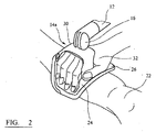
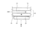
図1を参照して、デバイス2は、ハウジング6がその上に搭載され移動式カート4、および、直立体8であって、第2の直立体11が、ヒンジ領域9で直立体8に旋回可能に搭載される、直立体8を含む。アーム12は、ヒンジ領域10で直立体11に旋回可能に搭載される。アーム12は、ヒンジ付き継手16を介してヘッドピース14を支持する。ハウジング6は、電源、使用中にヘッドピース14を冷却するように構成された閉回路冷却システムの部分、および電子部品を閉囲する。デバイス用のユーザ操作可能なコントロールパネル18は、直立体8上の好都合な高さに搭載される。
In the figures, the same or similar parts are noted with the same reference numerals.
Referring to FIG. 1, the
使用中、デバイスは、図2に示すように、ヘッドピース14から、光増感剤が塗布された創傷に光を送出するように構成される。
デバイスおよびその動作が以下で詳細に述べられる。
In use, the device is configured to deliver light from the
The device and its operation are described in detail below.
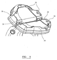
ヘッドピース14a(図1および2)および14b(図3〜16)は、処置される創傷(または他の病変部)を含む皮膚の表面に適合し、創傷に予め塗布された光増感剤を活性化するために、皮膚に光を当てるように構成される。図1または2を参照して、ヘッドピース14aは、ヒンジ付き継手16を介してアーム12上に旋回可能に搭載され、それにより、ヘッドピースが、創傷(図示せず)を含む身体部分22の皮膚にヘッドピースの発光面20が隣接して配置されうるように構成されることが可能になる。ヘッドピース14bは、アーム12(図3に示さず)上にヘッドピース14bがそれによって旋回可能に搭載されるボール31を含む。ヘッドピース14aは、2つのパネル24、26を含み、2つのパネル24、26は、パネルが、互いに対して旋回し、それにより、パネル24と26との間の角度を調整し、それにより、発光面20によって画定される形状が調整されるように、ヒンジを介して旋回可能に搭載される。同様に、ヘッドピース14bは、ヘッドピース14bのパネル24、26が、互いに対して旋回することを可能にするヒンジ28を含む。パネル24、26が旋回する結果として、発光面の形状は、デバイスを使用して処置される身体部分の形状にできる限り適合するように調整されてもよい。
ヘッドピースは、オペレータによって所定位置に容易に操作されうるように構成される。この点で、図2の実施形態のパネル24、26の上向き表面は、実質的に平坦で、架橋ピース30と共に、オペレータの手32を快適に受取ることができる開口を画定する。そのように配設されると、オペレータは、自分の手を撓ませることによってパネル24、26に旋回させ、それにより、所望の構成をパネルにとらせうる。図3以下の実施形態は、パネル24、26と共に、図2の実施形態の場合と同様にオペレータの手を受取るように構成されている開口35を画定する架橋配置構成33を備える。さらに、ノブ37は、オペレータが、旋回して所望の構成を画定するようにパネル24、26にさせうるさらなる手段として設けられる。
The head piece is configured so that it can be easily operated to a predetermined position by an operator. In this regard, the upwardly facing surfaces of the
デバイスのヒンジ28、ヒンジ付き継手16(またはボール31およびソケット(図示せず))、ヒンジ領域10、およびヒンジ領域9は、ヘッドピースが創傷に隣接して配置されると、ヘッドピースが所定位置に留まるように構成される。そのため、創傷を覆って所望位置にヘッドピースを配置することは、熟練または器用さをほとんど要しないことが理解されるであろう。
The
ヘッドピース14は、デバイスの発光面20から離れて外に光を送るように構成されている発光ダイオード(LED)のアレイ34(図3以下の実施形態の文脈で詳細に示され
るだけであるが)を組込む。LEDは、適切には、面20からの光出力が、面20にわたって実質的に一定強度であるように、ヒンジ28を横切るところでも共に接近している。LEDのアレイは、LEDを保護し、LEDと処置される創傷との直接接触を回避するために、それぞれのカバー(ヒンジ28のそれぞれの側に1つのカバー)を備えてもよい。こうしたカバーは、光散乱性があり(たとえば、透明ではなく拡散性があってよく)、それにより、面20から出力される光の均一性を改善するように構成される。一実施形態では、カバーは、硬化可能医療等級シリコーンを含んでもよい。こうした材料は、未硬化状態では、隣接するLED間のギャップを埋めるためにLED上に直接塗布されてもよい。材料の外側表面は、平滑な表面を画定するように表面処理されてもよい。硬化すると、シリコーンは、平滑で洗浄可能な外側表面を有する拡散カバーを画定する。
The
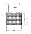
LEDの各アレイ34は、金属支持体上に搭載され、かつ、寸法約1.8cm×2.1cmの長方形アレイを画定するように構成された99個の別個のLED素子35を含む。アレイは、互いに隣接して搭載され、それにより、面20にわたってLEDの実質的に連続する配置構成を画定する。全体として、LEDは、100mW/cm2の出力を有する。こうした出力は、測定可能な時間にわたって(使用される光増感剤を活性化するのに必要とされる量の観点から)光の十分な量を送出することができることと、創傷を有害に加熱しうる、かつ/または、以降で述べる冷却デバイスを使用して伝導により逃がされる必要がある過剰の熱を生成させないこととの間の妥協を表す。
Each
LEDは、有利には好ましい光増感剤に関して使用されてもよい670±30nmのピーク波長を有する。
創傷は、熟練が無いかまたは半熟練のオペレータによってデバイスを使用して処置されてもよい。この点で、光増感剤は、所定の方法で創傷に塗布されうる。好ましい光増感剤は、創傷エリアの15マイクロリットル/cm2のレートにおいて0.025wt%の活性成分を含む処方を使用して塗布されてもよいフェノチアジンである。その後、デバイス2は、ヘッドピース14が創傷上に重ね合わされるように操作される。ヘッドピースの面20は創傷に接触してもよく、または、面は、以降で述べるスペーサを使用して創傷からわずかに間隔を空けられてもよい。いずれにしても、デバイスは、使用中に、創傷に適切なレベルの光を送出するように事前較正される。ヘッドピースが適切に配置されると、LEDは、オペレータがコントロールパネル18上の(または、ヘッドピース14自体の上の)ボタンを作動させるだけで動作してもよい。LEDは、その後、予め決められかつデバイス2に工場でプログラムされた期間の間、動作する。時間は、使用される光増感剤、LEDのパワー、ヘッドピースの位置(すなわち、創傷からのLEDの距離)に応じて計算される。しかし、オペレータは、処置で使用するための時間長または任意の他の有意な変数を自分で決めないことが理解されるべきである。したがって、オペレータは、適切でかつ有効な方法で創傷を処置する有意な熟練を働かせる必要が全くない。
The LED has a peak wavelength of 670 ± 30 nm which may advantageously be used with the preferred photosensitizer.
The wound may be treated using the device by an unskilled or semi-skilled operator. In this regard, the photosensitizer can be applied to the wound in a predetermined manner. A preferred photosensitizer is phenothiazine, which may be applied using a formulation containing 0.025 wt% active ingredient at a rate of 15 microliters / cm 2 in the wound area. The
上述したように、創傷からのLEDの距離を予め決めることは、創傷が光にどれだけ長く曝露されるべきかを確定するときの、かつ/または、創傷に対する光の適用における一貫性を保証するための因子である。一実施形態では、光増感剤が塗布された創傷を覆ってプラスチック膜が単に適用され、その後、ヘッドピースが、使用中にプラスチック膜に直接接触してもよい。図3以下の実施形態では、特に図9に示すように、ヘッドピースの面20は、ヘッドピースの周縁においてLEDの周りにスペーサ50を組込む。スペーサは、面20から突出し、使用中に創傷の周りのエリアに接触するように構成される。突出する個々のスペーサの代替として、スペーサは、LEDの周りの継ぎ目なし棚によって画定されてもよい。両方の場合に、スペーサ(複数可)は、LEDと創傷の表面との距離をセットし、それにより、再現性のある光適用量が創傷に送出されることを保証する。
As described above, predetermining the distance of the LED from the wound ensures consistency in determining how long the wound should be exposed to light and / or in the application of light to the wound. Is a factor for. In one embodiment, a plastic film may simply be applied over the wound to which the photosensitizer has been applied, after which the headpiece may be in direct contact with the plastic film during use. In the embodiment below FIG. 3, the
一部の実施形態では、ヘッドピースの面20は、使用中に創傷に接触し、患者間の感染
の蔓延のリスクを回避するために後で廃棄されてもよい使い捨て保護カバーを含んでもよい。
In some embodiments, the
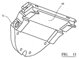
LEDが熱を発生すること、および、任意のかなりの温度まで創傷を加熱することが望ましくないため、創傷を通過する熱の量を制限することが重要であることが理解されるであろう。ヘッドピースの面20は約40°を超えないことが好ましい。これを達成するために、ヘッドピースは、図11〜14に示す水冷却システムを含む。冷却システムは、ヒンジ28のそれぞれの側に、それぞれのアルミニウム本体60を含み、アルミニウム本体60内で、トラック62が、その上向き面64内に画定される。LED組立体29(図7および14)は、下面66に接触し、熱接着剤の層68によって下面66に固定され、配置構成は、熱が、LEDから、LEDがその上に搭載される金属支持体を介して、熱接着剤を介して、本体60内に伝導されるようなものである。本体60は、アルミニウム上部プレート70によってカバーされる。
It will be appreciated that it is important to limit the amount of heat that passes through the wound, as it is undesirable for the LED to generate heat and to heat the wound to any significant temperature. The
本体60は、トラック62の第1の端部74に水が送出されることを可能にするように構成されている水入口72を含む。トラックは、回旋状に本体60を横切り、本体60上の位置80の出口に連通する第2の端部76を含む。ヒンジ28の他の側では、冷却システムは、所望される配置構成の鏡像である。
The
水は、直立体8、11、およびアーム12を通過する第1の導管を介してハウジング6(図1)からヘッドピースへ送出される。ヘッドピースに近い領域では、第1の導管が分岐し、別個の導管がヒンジ28の対向する側に配列された、本体60内のそれぞれの入口72に接続される。
Water is delivered from the housing 6 (FIG. 1) to the headpiece via a first conduit passing through the
水は、ヒンジ28の対向する側のトラック62の出口に連通するそれぞれの導管を介してヘッドピースから除去され、その後、直立体8、11、およびアーム12を通過し、ハウジング6に戻る第2の導管内に給送される。
The water is removed from the headpiece via respective conduits that communicate with the exit of the
ハウジング6は、熱交換器およびポンプを含み、それにより、ヘッドピースに冷却水を送出し、LEDからヘッドピースに伝導された熱によって加熱された水を除去するように構成される。熱交換器は、その後、加熱された水を冷却し、それを再循環させる。 The housing 6 includes a heat exchanger and a pump, which is configured to deliver cooling water to the headpiece and remove water heated by heat conducted from the LED to the headpiece. The heat exchanger then cools the heated water and recirculates it.
上述したデバイス2に関する変形および/またはデバイス2に対する追加は、以下で述べられる。
一実施形態では、デバイス2は、LEDがフルパワーで動作する前に、創傷に光を送出するために面20が正しく配置されているかどうかを判定する手段を含むようになっていてもよい。この点で、LEDは、オペレータがデバイスの「ポジショニング」または「照準」モードを単に選択することなどによって、低いパワー、たとえば、通常の処置パワーの約10%で動作するように構成されてもよい。使用中に、オペレータは、面20からわずかに間隔を空けるが、創傷の近くに面20を配置し、LEDの低パワー(ポジショニング/照準)モードが選択され、オペレータは、その後、創傷を観察し、LEDからの光が十分に創傷に送られているかどうかを評価してもよい。ヘッドピースは、その後、必要である場合、再配置されてもよい。ヘッドピースは、最適に配置されているように見えると、(たとえば、創傷表面に接する、または、創傷表面からわずかに間隔を空けた)その動作位置に移動され、LEDがフルパワーで動作されてもよい。
Variations on and / or additions to
In one embodiment,
ヘッドピース14bは、患者の異なるロケーションの創傷を処置するいくつかの方法で使用されてもよい。ある場合には、たとえば創傷が小さな面積を有する場合、パネル24、26の一方だけが、創傷上に重ね合わされてもよい。他の実施形態では、創傷は、パネル24と26との間に配置されてもよい。ある場合には、それぞれのパネル48は、発光
面20が大きな曲率半径を有するように、ヒンジ28を横切って互いに実質的に一直線に配置されてもよく、また、図15に示すように、大腿(または同様なもの)に接触してもよい。別の場合には、それぞれのパネル24、26は、パネル間で鋭角が画定されるように旋回されてもよく、その結果、発光面は、図16に示すように、小さな曲率半径を有する身体部分(たとえば、足首)に接触してもよい構成を画定する。
図3以下の実施形態では、LEDのラインが、平坦面上に配列され、平坦面が互いに傾斜していることが理解されるべきである。この配置構成は、図17において誇張されている。図を参照して、ヘッドピース14は、ヒンジ28bを介して旋回可能に搭載される第1および第2の半分40、42を含む。それぞれの半分40、42は、実質的に平坦であり、かつ、LEDのアレイ34を組込む3つのパネル44、46、48で構成される。それぞれの半分は、同じ半分においてそれぞれの他のパネルに対して所定位置に固定されるパネルを備える。パネル44は、パネル46に対して鈍角を画定し、パネル48は、パネル46に対して鈍角を画定する。
In the embodiments below FIG. 3, it should be understood that the lines of LEDs are arranged on a flat surface and the flat surfaces are inclined with respect to each other. This arrangement is exaggerated in FIG. Referring to the figure, the
さらなる代替のヘッドピースが設けられてもよく、たとえば、ヘッドピースは、身体部分に関するより大きな適合性を可能にするために、複数のヒンジを含んでもよい。たとえば、ヒンジは、図17の点100、102、104、106の1つまたは複数に設けられうる。さらに、本明細書に述べる構成を収容するより大きなまたはより小さなヘッドピースが設けられてもよい。
Additional alternative headpieces may be provided, for example, the headpiece may include multiple hinges to allow greater conformity with the body part. For example, a hinge may be provided at one or more of the
広い範囲の患者および創傷が処置されることを可能にするために、放射放出デバイスは、ヘッドピースが交換可能であるように構成されてもよい。そのため、装置は、図1に述べる移動式カート4および複数の異なるヘッドピースを組込んでもよい。ヘッドピースは、異なるサイズおよび/または異なる構成を有してもよい。ヘッドピースを変更することは、比較的簡単である。第1に、冷却システムの水道管が、任意の電気接続部がそうであるように取外される。第2に、ヘッドピースが、ヒンジ付き継手16から取外される。第3に、新しいヘッドピースが選択され、水道管および電気接続部が作られる。 In order to allow a wide range of patients and wounds to be treated, the radiation emitting device may be configured such that the headpiece is replaceable. As such, the apparatus may incorporate the mobile cart 4 described in FIG. 1 and a plurality of different headpieces. The head pieces may have different sizes and / or different configurations. Changing the headpiece is relatively easy. First, the water pipe of the cooling system is removed as is any electrical connection. Second, the headpiece is removed from the hinged joint 16. Third, a new headpiece is selected and water pipes and electrical connections are made.
Claims (25)
のデバイス。 14. A device according to any one of the preceding claims comprising cooling means for dissipating heat from the radiation emitting means, wherein the cooling means is configured to remove at least 5000 joules / minute.
(i)処置エリアを光増感剤化合物に接触させる工程と、
(ii)前記光増感剤化合物を活性化するために、請求項1〜18のいずれか1項に記載の処置デバイスを使用して、前記処理エリアに放射を送出する工程とを備える方法。 In a method for treating a treatment area,
(I) contacting the treatment area with a photosensitizer compound;
(Ii) delivering radiation to the processing area using the treatment device of any one of claims 1 to 18 to activate the photosensitizer compound.
Applications Claiming Priority (3)
| Application Number | Priority Date | Filing Date | Title |
|---|---|---|---|
| GB0807850.3 | 2008-04-30 | ||
| GBGB0807850.3A GB0807850D0 (en) | 2008-04-30 | 2008-04-30 | Treatment device |
| PCT/GB2009/050420 WO2009133385A1 (en) | 2008-04-30 | 2009-04-24 | Treatment device for delivering radiation to an external area of the human body |
Publications (2)
| Publication Number | Publication Date |
|---|---|
| JP2011518632A true JP2011518632A (en) | 2011-06-30 |
| JP2011518632A5 JP2011518632A5 (en) | 2012-05-31 |
Family
ID=39522800
Family Applications (1)
| Application Number | Title | Priority Date | Filing Date |
|---|---|---|---|
| JP2011506776A Pending JP2011518632A (en) | 2008-04-30 | 2009-04-24 | Device for delivering radiation to the external area of the human body |
Country Status (5)
| Country | Link |
|---|---|
| US (1) | US20110106222A1 (en) |
| EP (1) | EP2280763A1 (en) |
| JP (1) | JP2011518632A (en) |
| GB (1) | GB0807850D0 (en) |
| WO (1) | WO2009133385A1 (en) |
Cited By (2)
| Publication number | Priority date | Publication date | Assignee | Title |
|---|---|---|---|---|
| JP2013146528A (en) * | 2012-01-19 | 2013-08-01 | Forward Electronics Co Ltd | Photo-stimulation method and device |
| JP2015528338A (en) * | 2012-08-30 | 2015-09-28 | フォトキュア エイエスエイ | Dual panel photodynamic therapy lamp |
Families Citing this family (8)
| Publication number | Priority date | Publication date | Assignee | Title |
|---|---|---|---|---|
| US20100331918A1 (en) * | 2009-06-30 | 2010-12-30 | Boston Scientific Neuromodulation Corporation | Moldable charger with curable material for charging an implantable pulse generator |
| US20100331919A1 (en) * | 2009-06-30 | 2010-12-30 | Boston Scientific Neuromodulation Corporation | Moldable charger having hinged sections for charging an implantable pulse generator |
| DE202010018421U1 (en) | 2010-10-06 | 2016-06-23 | Herbert Waldmann Gmbh & Co Kg | Irradiation device with ergonomic adjustment options |
| US9597526B2 (en) * | 2012-01-20 | 2017-03-21 | Meditech International Inc. | Flexible light treatment head |
| US10603508B2 (en) * | 2015-10-15 | 2020-03-31 | Dusa Pharmaceuticals, Inc. | Adjustable illuminators and methods for photodynamic therapy and diagnosis |
| EP3851161A1 (en) * | 2015-10-15 | 2021-07-21 | DUSA Pharmaceuticals, Inc. | Adjustable illuminator for photodynamic therapy and diagnosis |
| US10357567B1 (en) | 2018-01-12 | 2019-07-23 | Dusa Pharmaceuticals, Inc. | Methods for photodynamic therapy |
| US11331513B2 (en) | 2019-09-07 | 2022-05-17 | National Laser Company | Pain treatment device |
Family Cites Families (10)
| Publication number | Priority date | Publication date | Assignee | Title |
|---|---|---|---|---|
| US4930504A (en) * | 1987-11-13 | 1990-06-05 | Diamantopoulos Costas A | Device for biostimulation of tissue and method for treatment of tissue |
| US5278432A (en) * | 1992-08-27 | 1994-01-11 | Quantam Devices, Inc. | Apparatus for providing radiant energy |
| US5698866A (en) * | 1994-09-19 | 1997-12-16 | Pdt Systems, Inc. | Uniform illuminator for phototherapy |
| US6436127B1 (en) * | 1997-10-08 | 2002-08-20 | The General Hospital Corporation | Phototherapy methods and systems |
| GB0113899D0 (en) * | 2001-06-07 | 2001-08-01 | Photocure Asa | Photodynamic therapy lamp |
| US20060265028A1 (en) * | 2003-04-23 | 2006-11-23 | Qlt Inc. | Hair growth |
| CA2555396C (en) * | 2004-02-06 | 2016-03-15 | Daniel Barolet | Method and device for the treatment of mammalian tissues |
| AT503079B1 (en) * | 2005-04-29 | 2008-03-15 | Paris Lodron Uni Salzburg | DEVICE FOR IMPLEMENTING PHOTODYNAMIC TREATMENTS |
| TWM279352U (en) * | 2005-05-06 | 2005-11-01 | Lighthouse Technology Co Ltd | Photo power supply device capable of being controlled by programs |
| US20070139930A1 (en) * | 2005-12-19 | 2007-06-21 | Paul Spivak | Method and system for led light therapy |
-
2008
- 2008-04-30 GB GBGB0807850.3A patent/GB0807850D0/en not_active Ceased
-
2009
- 2009-04-24 US US12/736,679 patent/US20110106222A1/en not_active Abandoned
- 2009-04-24 WO PCT/GB2009/050420 patent/WO2009133385A1/en active Application Filing
- 2009-04-24 EP EP09738415A patent/EP2280763A1/en not_active Withdrawn
- 2009-04-24 JP JP2011506776A patent/JP2011518632A/en active Pending
Cited By (2)
| Publication number | Priority date | Publication date | Assignee | Title |
|---|---|---|---|---|
| JP2013146528A (en) * | 2012-01-19 | 2013-08-01 | Forward Electronics Co Ltd | Photo-stimulation method and device |
| JP2015528338A (en) * | 2012-08-30 | 2015-09-28 | フォトキュア エイエスエイ | Dual panel photodynamic therapy lamp |
Also Published As
| Publication number | Publication date |
|---|---|
| US20110106222A1 (en) | 2011-05-05 |
| EP2280763A1 (en) | 2011-02-09 |
| WO2009133385A1 (en) | 2009-11-05 |
| GB0807850D0 (en) | 2008-06-04 |
Similar Documents
| Publication | Publication Date | Title |
|---|---|---|
| JP2011518632A (en) | Device for delivering radiation to the external area of the human body | |
| US8470010B2 (en) | Systems and methods for treating superficial venous malformations like spider veins | |
| Schmidt et al. | Light-emitting diodes as a light source for intraoperative photodynamic therapy | |
| Darlenski et al. | Photodynamic therapy in dermatology: past, present, and future | |
| ES2454974T3 (en) | Apparatus for optical inhibition of photodynamic therapy | |
| Wilson | Photodynamic therapy for cancer: principles | |
| Bown et al. | Photodynamic therapy with porphyrin and phthalocyanine sensitisation: quantitative studies in normal rat liver | |
| Saini et al. | Photodynamic therapy: a review and its prospective role in the management of oral potentially malignant disorders | |
| Chen et al. | New technology for deep light distribution in tissue for phototherapy | |
| Ris et al. | Photodynamic therapy with m‐tetrahydroxyphenylchlorin in vivo: optimization of the therapeutic index | |
| Roberts et al. | Photodynamic therapy of primary skin cancer: a review | |
| Yavari et al. | An overview on preclinical and clinical experiences with photodynamic therapy for bladder cancer | |
| Hürlimann et al. | Photodynamic therapy of superficial basal cell carcinomas using topical 5-aminolevulinic acid in a nanocolloid lotion | |
| JP2015528338A (en) | Dual panel photodynamic therapy lamp | |
| US8535360B2 (en) | Systems and methods for treating superficial venous malformations like spider veins | |
| JP2009532079A (en) | Light beauty device | |
| CA2473924A1 (en) | Systems and methods for photodynamic therapy | |
| Lee et al. | In situ comparison of 665 nm and 633 nm wavelength light penetration in the human prostate gland | |
| Jerjes et al. | The application of photodynamic therapy in the head and neck | |
| Shackley et al. | Photodynamic therapy | |
| Garofalo et al. | Combination of laser therapy and photodynamic therapy with 5-aminolevulinic acid patch for the treatment of actinic cheilitis | |
| Ravi et al. | Sensitization and photodynamic therapy of normal pancreas, duodenum and bile ducts in the hamster using 5-aminolaevulinic acid | |
| Lee et al. | The immunogenetic aspects of photodynamic therapy | |
| Lytle et al. | Light-emitting diode source for photodynamic therapy | |
| Boehncke | Topical photodynamic therapy for psoriasis |
Legal Events
| Date | Code | Title | Description |
|---|---|---|---|
| RD04 | Notification of resignation of power of attorney |
Free format text: JAPANESE INTERMEDIATE CODE: A7424 Effective date: 20120112 |
|
| A521 | Written amendment |
Free format text: JAPANESE INTERMEDIATE CODE: A523 Effective date: 20120330 |
|
| A621 | Written request for application examination |
Free format text: JAPANESE INTERMEDIATE CODE: A621 Effective date: 20120330 |
|
| A072 | Dismissal of procedure [no reply to invitation to correct request for examination] |
Free format text: JAPANESE INTERMEDIATE CODE: A073 Effective date: 20130806 |