JP2011516170A - Medical care product including a valve and kit including the same - Google Patents
Medical care product including a valve and kit including the same Download PDFInfo
- Publication number
- JP2011516170A JP2011516170A JP2011503141A JP2011503141A JP2011516170A JP 2011516170 A JP2011516170 A JP 2011516170A JP 2011503141 A JP2011503141 A JP 2011503141A JP 2011503141 A JP2011503141 A JP 2011503141A JP 2011516170 A JP2011516170 A JP 2011516170A
- Authority
- JP
- Japan
- Prior art keywords
- medical dressing
- support
- valve
- wound
- fluid
- Prior art date
- Legal status (The legal status is an assumption and is not a legal conclusion. Google has not performed a legal analysis and makes no representation as to the accuracy of the status listed.)
- Withdrawn
Links
Images


Classifications
-
- A—HUMAN NECESSITIES
- A61—MEDICAL OR VETERINARY SCIENCE; HYGIENE
- A61M—DEVICES FOR INTRODUCING MEDIA INTO, OR ONTO, THE BODY; DEVICES FOR TRANSDUCING BODY MEDIA OR FOR TAKING MEDIA FROM THE BODY; DEVICES FOR PRODUCING OR ENDING SLEEP OR STUPOR
- A61M27/00—Drainage appliance for wounds or the like, i.e. wound drains, implanted drains
-
- A—HUMAN NECESSITIES
- A61—MEDICAL OR VETERINARY SCIENCE; HYGIENE
- A61M—DEVICES FOR INTRODUCING MEDIA INTO, OR ONTO, THE BODY; DEVICES FOR TRANSDUCING BODY MEDIA OR FOR TAKING MEDIA FROM THE BODY; DEVICES FOR PRODUCING OR ENDING SLEEP OR STUPOR
- A61M1/00—Suction or pumping devices for medical purposes; Devices for carrying-off, for treatment of, or for carrying-over, body-liquids; Drainage systems
- A61M1/71—Suction drainage systems
- A61M1/74—Suction control
-
- A—HUMAN NECESSITIES
- A61—MEDICAL OR VETERINARY SCIENCE; HYGIENE
- A61M—DEVICES FOR INTRODUCING MEDIA INTO, OR ONTO, THE BODY; DEVICES FOR TRANSDUCING BODY MEDIA OR FOR TAKING MEDIA FROM THE BODY; DEVICES FOR PRODUCING OR ENDING SLEEP OR STUPOR
- A61M1/00—Suction or pumping devices for medical purposes; Devices for carrying-off, for treatment of, or for carrying-over, body-liquids; Drainage systems
- A61M1/90—Negative pressure wound therapy devices, i.e. devices for applying suction to a wound to promote healing, e.g. including a vacuum dressing
- A61M1/91—Suction aspects of the dressing
- A61M1/915—Constructional details of the pressure distribution manifold
-
- A—HUMAN NECESSITIES
- A61—MEDICAL OR VETERINARY SCIENCE; HYGIENE
- A61M—DEVICES FOR INTRODUCING MEDIA INTO, OR ONTO, THE BODY; DEVICES FOR TRANSDUCING BODY MEDIA OR FOR TAKING MEDIA FROM THE BODY; DEVICES FOR PRODUCING OR ENDING SLEEP OR STUPOR
- A61M2205/00—General characteristics of the apparatus
- A61M2205/33—Controlling, regulating or measuring
- A61M2205/3331—Pressure; Flow
- A61M2205/3334—Measuring or controlling the flow rate
Landscapes
- Health & Medical Sciences (AREA)
- Heart & Thoracic Surgery (AREA)
- Animal Behavior & Ethology (AREA)
- General Health & Medical Sciences (AREA)
- Anesthesiology (AREA)
- Biomedical Technology (AREA)
- Hematology (AREA)
- Life Sciences & Earth Sciences (AREA)
- Veterinary Medicine (AREA)
- Engineering & Computer Science (AREA)
- Public Health (AREA)
- Vascular Medicine (AREA)
- Otolaryngology (AREA)
- Media Introduction/Drainage Providing Device (AREA)
- External Artificial Organs (AREA)
- Materials For Medical Uses (AREA)
- Surgical Instruments (AREA)
Abstract
陰圧創傷閉鎖法を提供するために使用できる医療用手当て用品及び医療用手当て用品キット。医療用手当て用品は、1つ以上の通常閉のバルブを含み、かつスタンドオフ要素、バリア要素、閉止要素、及び隔膜要素を含み得る。医療用手当て用品キットは、ポンプ、流体トラップ及び/又は取り付け部を更に含み得る。 A medical dressing and a medical dressing kit that can be used to provide a negative pressure wound closure method. The medical dressing includes one or more normally closed valves and can include a standoff element, a barrier element, a closure element, and a diaphragm element. The medical dressing kit may further include a pump, fluid trap and / or attachment.
Description
本発明は、陰圧創傷閉鎖法を提供するために使用することができる、医療用手当て用品及び医療用手当て用品キットを提供し、より詳細には、本発明は、1つ以上の通常閉のバルブを含む医療用手当て用品と、かかる医療用手当て用品を含むキットを提供する。 The present invention provides a medical dressing and a medical dressing kit that can be used to provide a negative pressure wound closure method, and more particularly, the present invention includes one or more normally closed closures. A medical dressing including a valve and a kit including such a medical dressing are provided.
医療用手当て用品が、創傷を覆って所定の位置にとどまる時間の長さは、多くの要因によって制限され得る。創傷内の流体の蓄積は、医療用手当て用品の可使時間を制限し得る要因である。一部の医療用手当て用品には、医療用手当て用品の、創傷を覆って定位置にとどまることができる時間を増加させるために、吸収材料が組み込まれている。例えば、ヒドロコロイド、発泡体、ヒドロゲル、不織布(アルギン酸塩及びカルボキシメチルセルロースなど)及びこれらの組み合わせなどの吸収材料が、医療用手当て用品の耐用寿命を増加させるために使用されてきた。 The length of time that the medical dressing stays in place over the wound can be limited by many factors. Fluid accumulation in the wound is a factor that can limit the pot life of a medical dressing. Some medical dressings incorporate an absorbent material to increase the amount of time that the medical dressing can stay in place over the wound. For example, absorbent materials such as hydrocolloids, foams, hydrogels, nonwovens (such as alginate and carboxymethylcellulose) and combinations thereof have been used to increase the useful life of medical dressings.
患者から医療用手当て用品を取り外す必要なく創傷医療用手当て用品の真下から流体が除去されるような、医療用手当て用品の耐用寿命を増加させるための他のアプローチも陰圧創傷閉鎖法の実施に含まれた。陰圧創傷治療を提供するために構成された医療用手当て用品(例えば、米国特許第4,969,880号、同第5,261,893号、同第5,527,293号、及び同第6,071,267号(全ては、Zamierowskiに付与)に記載されるもの等)は、多くの場合、創傷を覆って配置されるなどの、創傷の無菌性を損ない得る構造を有する。これらの製品は多くの場合、複数ピースの医療用手当て用品を通してか、あるいは単一ピースの医療用手当て用品の下のいずれかで導入される、チューブ又は創傷ドレーンを必要とする。いずれの場合にも、チューブ又は創傷ドレーンの間に良好な密閉を得ることは(不可能ではないにしても)難しく、治療時に創傷へと空気が漏れて入ることがある。この空気は、創傷内に混入物を運び、及び/又は圧力に基づく治療の有効性を損なう可能性がある。 Other approaches to increase the useful life of medical dressings, such as removing fluid from directly under the wound dressing without having to remove the dressing from the patient, can also be used to implement negative pressure wound closure. Included. Medical dressings configured to provide negative pressure wound treatment (eg, US Pat. Nos. 4,969,880, 5,261,893, 5,527,293, and US Pat. No. 6,071,267 (all described in Zamierowski, etc.) has a structure that can compromise the sterility of the wound, such as often placed over the wound. These products often require tubes or wound drains that are introduced either through multiple pieces of medical dressing or under a single piece of medical dressing. In either case, obtaining a good seal between the tube or wound drain is difficult (if not impossible) and air can leak into the wound during treatment. This air can carry contaminants into the wound and / or impair the effectiveness of the pressure-based treatment.
米国特許第5,478,333号は、胸部創傷用の、一方向弁を備える創傷医療用手当て用品を開示する。医療用手当て用品はまた、一方向弁に挿入される「吸引装置」と併せて使用することもできる。陰圧は、バルブを通して吸引装置を挿入することで適用される。 US Pat. No. 5,478,333 discloses a wound care dressing with a one-way valve for chest wounds. The medical dressing can also be used in conjunction with a “suction device” that is inserted into a one-way valve. Negative pressure is applied by inserting a suction device through the valve.
本発明は、創傷又は他の身体部位を覆って密閉された環境を提供するために使用できる、医療用手当て用品を提供する。医療用手当て用品は、密閉された環境から流体を取り除くことができるようにする、1つ以上の通常閉のバルブを含む。密閉された環境から取り除かれる流体には、気体及び/又は液体(壊死組織、血栓などの分散した固体粒子を含有する場合がある)を挙げることができる。流体の除去は、医療用手当て用品を取り外すか、ないしは別の方法で医療用手当て用品を阻害することなく、通常閉のバルブを通して実施することができる。 The present invention provides a medical dressing that can be used to provide a sealed environment over a wound or other body part. The medical dressing includes one or more normally closed valves that allow fluid to be removed from the sealed environment. Fluids that are removed from the enclosed environment can include gases and / or liquids (which may contain dispersed solid particles such as necrotic tissue, thrombi, etc.). Fluid removal can be performed through a normally closed valve without removing the medical dressing or otherwise obstructing the medical dressing.
本明細書で使用されるように、用語「密閉された環境」は、流体(及び固体)が、創傷を覆って取り付けられた医療用手当て用品の外面の周囲雰囲気から、密閉された環境へと自由に入ることができないことを意味する。密閉された環境には、好ましくは、密閉された環境において陰圧が維持され得るような、医療用手当て用品と創傷周囲の表面との間の気密密閉が含まれる。例えば、13.3kPa(100mmHg)の真空(言い換えれば、大気圧を13.3kPa(100mmHg)下回る圧力)及び場合によっては26.7kPa(200mmHg)の真空を(少なくとも本明細書に記載されるように一時的に)保持する能力を有する医療用手当て用品が好ましい。一部の従来の医療用手当て用品は、このような密閉された環境を提供することができるが、本発明の医療用手当て用品は、医療用手当て用品の一部として提供されたバルブを通して、密閉された環境から流体(液体及び/又は気体)を取り除くために有利な機会もまた提供しながら、上記の環境を提供することができる。 As used herein, the term “sealed environment” refers to the fluid (and solids) from the ambient atmosphere of the outer surface of a medical dressing attached over the wound to the sealed environment. It means you can't enter freely. The sealed environment preferably includes a hermetic seal between the medical dressing and the surface surrounding the wound such that a negative pressure can be maintained in the sealed environment. For example, a vacuum of 13.3 kPa (100 mmHg) (in other words, a pressure 13.3 kPa (100 mmHg) below atmospheric pressure) and possibly a vacuum of 26.7 kPa (200 mmHg) (at least as described herein). Medical dressings that have the ability to (temporarily) hold are preferred. While some conventional medical dressings can provide such a sealed environment, the medical dressings of the present invention are sealed through a valve provided as part of the medical dressing. The above environment can be provided while also providing an advantageous opportunity to remove fluid (liquid and / or gas) from the treated environment.
本発明の医療用手当て用品との関連において、バルブは、好ましくは相対的に薄型であるか又は低い高さを有する。好ましくは、低い外形のバルブは、医療用手当て用品が外力(例えば、寝具、衣類などからの外力)によって阻害される可能性を減じる。低い外形のバルブは、例えば、患者が座っている間、横になっている間、及び/又は立っている間に、患者の体重がかかるような位置に医療用手当て用品を配置した場合の、患者の快適さを改善することもできる。本明細書で述べるような、バルブの低い外形の性質は、バルブ及び支持体、バルブの高さ又は厚さなどによって画定される、死容積に関して特徴付けることもできる。本発明の医療用手当て用品に使用されるバルブはまた、好ましくは、例えば、患者が医療用手当て用品のバルブを含む部分上に長時間にわたって(例えば、2時間以上にわたって)横たわったときに、創傷の損壊を引き起こすような圧迫部分を作り出す可能性を減じるように、柔らかく、柔軟性がある。好ましいバルブは、医療用手当て用品へと取り付けられても柔軟性があるバルブであり、医療従事者などの人間の親指と人差し指の間で少なくとも一方向に、及び好ましくは複数の方向に手動で折畳むことができる。最も好ましいバルブは折り畳みから完全に元に戻る。これらの好ましいバルブは、少なくとも2枚のフィルム層の積層からなる。 In the context of the medical dressing of the present invention, the valve is preferably relatively thin or has a low height. Preferably, the low profile valve reduces the likelihood that the medical dressing will be hindered by external forces (eg, external forces from bedding, clothing, etc.). A low profile valve can be used, for example, when a medical dressing is placed in such a position that the patient's weight is applied while the patient is sitting, lying down and / or standing. Patient comfort can also be improved. The low profile nature of the valve, as described herein, can also be characterized in terms of dead volume, defined by the valve and support, the height or thickness of the valve, and the like. The valve used in the medical dressing of the present invention is also preferably wound when, for example, the patient lies on the part containing the valve of the medical dressing for an extended period of time (eg, over 2 hours). It is soft and flexible so as to reduce the possibility of creating pressure parts that cause damage. A preferred valve is a valve that is flexible even when attached to a medical dressing, and is manually folded in at least one direction, and preferably in multiple directions, between the thumb and index finger of a human health professional or the like. Can be folded. The most preferred valve is completely restored from folding. These preferred valves consist of a laminate of at least two film layers.
密閉された環境からの流体除去は、創傷を覆って医療用手当て用品が配置された創傷に、陰圧又は減圧治療を施すのに有用であり得る。好適なバルブの使用により、本発明の医療用手当て用品によって作り出された密閉された環境は、好ましくは、密閉された環境と流体連通された、能動的な減圧供給源が存在しなくとも陰圧(すなわち、周囲の大気圧を下回る圧力)を維持することができる。換言すれば、本発明の医療用手当て用品を使用することで、密閉された環境からの流体の能動的な除去の間、陰圧又は減圧を有する密閉された環境を維持することができる。結果として、医療用手当て用品は、陰圧又は減圧環境に、単に断続的な又は周期的な流体除去を提供することができる。 Fluid removal from a sealed environment can be useful for applying negative or reduced pressure treatments to wounds where medical dressings are placed over the wound. With the use of a suitable valve, the sealed environment created by the medical dressing of the present invention preferably has a negative pressure even in the absence of an active vacuum source in fluid communication with the sealed environment. (That is, a pressure below the ambient atmospheric pressure) can be maintained. In other words, by using the medical dressing of the present invention, a sealed environment with negative or reduced pressure can be maintained during active removal of fluid from the sealed environment. As a result, the medical dressing can simply provide intermittent or periodic fluid removal in a negative or reduced pressure environment.
医療用手当て用品によって密閉された環境において維持される陰圧の程度は、典型的には経時的に(密閉された環境からの流体の能動的な除去の間に最高値に達した後に)低下するが、医療用手当て用品が少なくともある程度の有意な期間にわたって、陰圧を維持する能力を有することが好ましい場合もある。いくつかの実施形態においては、医療用手当て用品が、1分以上、5分以上、10分以上、15分以上、30分以上、又は更には60分以上にわたって、密閉された環境において(能動的な流体除去が存在しなくとも)少なくともある程度の陰圧を維持できることが好ましい場合もある。 The degree of negative pressure maintained in a sealed environment by a medical dressing typically decreases over time (after reaching a maximum during active removal of fluid from the sealed environment) However, it may be preferred that the medical dressing has the ability to maintain negative pressure for at least some significant period. In some embodiments, the medical dressing is in an enclosed environment (actively for 1 minute or more, 5 minutes or more, 10 minutes or more, 15 minutes or more, 30 minutes or more, or even 60 minutes or more. It may be preferable to be able to maintain at least some negative pressure (even if no fluid removal is present).
医療用手当て用品によって画定された密閉された環境内部の陰圧の低下は、様々な原因により生じ得る。例えば低下の一部は、医療用手当て用品の支持体及び/又は医療用手当て用品を患者に取り付けている接着剤を通っての、密閉された環境への気体の拡散によるものである場合がある。密閉された環境における陰圧低下の他の原因は、患者からの(言い換えれば、創傷自体及び/又は創傷の周囲の組織による)気体及び/又は液体が、密閉された環境に入ることによってもたらされる場合がある。 The reduction in negative pressure within the sealed environment defined by the medical dressing can be caused by a variety of causes. For example, some of the degradation may be due to the diffusion of gas into the sealed environment through the support of the medical dressing and / or the adhesive attaching the medical dressing to the patient . Another cause of negative pressure drop in a sealed environment is caused by gas and / or liquid from the patient (in other words, by the wound itself and / or tissue surrounding the wound) entering the sealed environment. There is a case.
密閉された環境内部の陰圧を保つために、一方向弁として医療用手当て用品と共に使用される、通常閉のバルブは、好ましいものであり得る。換言すれば、バルブは流体を一方向(密閉された環境外)に流れさせ、かつ反対方向(密閉された環境内)への流れを制限するか又は妨げるのが、好ましいものであり得る。 A normally closed valve used with a medical dressing as a one-way valve to maintain negative pressure inside a sealed environment may be preferred. In other words, it may be preferable for the valve to allow fluid to flow in one direction (outside the sealed environment) and restrict or prevent flow in the opposite direction (in the sealed environment).
様々な実施形態において、医療用手当て用品は、バルブに開放流体経路を提供するためのスタンドオフ要素(密閉された環境において陰圧下での閉止に抵抗する)、バリア要素(バルブ詰まりを抑えるため)、すなわち隔膜要素、及び/又は閉止要素を含むこともできる。場合によっては、閉止要素が取り外されるまでの間でバルブが閉じられるように、閉止要素を、バルブを覆わせて提供することもできる。 In various embodiments, the medical dressing includes a standoff element (to resist closure under negative pressure in a sealed environment) and a barrier element (to reduce valve clogging) to provide an open fluid path to the valve. I.e. a diaphragm element and / or a closure element. In some cases, a closure element can be provided covering the valve so that the valve is closed until the closure element is removed.
閉止要素は、(バルブから取り外した後に)医療用手当て用品上の違う部位に再配置させることができるように接着的に取り付けることができ、あるいはそれらは、例えば、バルブの適切な閉止を確実にするか及び/又は医療用手当て用品によって作り出された密閉された環境から外への流体の望まない漏れを減少させるために、密閉された環境から流体を取り除いた後に、バルブを覆って再配置させてもよい。いくつかの実施形態においては、バルブを覆っての閉止要素の使用は、a)従来の医療用手当て用品(すなわち、任意のバルブを含まず、したがって実質的に望まない漏れが生じる可能性を有さない)の可撓性、及びb)医療用手当て用品によって画定された密閉された環境から流体を除去させるためのバルブを提供することにより陰圧創傷閉鎖法で使用するために構成された医療用手当て用品の可撓性、を提供する場合がある。 The closure element can be adhesively attached so that it can be repositioned to a different location on the medical dressing (after removal from the valve), or they ensure, for example, proper closure of the valve And / or repositioning over the valve after removing the fluid from the sealed environment to reduce unwanted leakage of fluid out of the sealed environment created by the medical dressing May be. In some embodiments, the use of a closure element over the valve may include: a) conventional medical dressings (ie, not including any valves and thus potentially causing substantially unwanted leakage). Medical) configured for use in a negative pressure wound closure method by providing a valve for removing fluid from the sealed environment defined by the medical dressing May provide flexibility of care products.
本発明の医療用手当て用品の使用に関係付けることができる潜在的な利点としては、いくつかの例においては、陰圧は同時に深刻な切開創傷の縁部を有利に引くことができることから、より迅速な回復、感染率の減少及び/又は改善された美容上の結果(瘢痕化の減少)を提供する可能性がある。 A potential advantage that can be related to the use of the medical dressing of the present invention is that, in some instances, negative pressure can at the same time advantageously pull the edge of a serious incision wound, It may provide rapid recovery, reduced infection rates and / or improved cosmetic results (reduced scarring).
一態様では、本発明は、内側表面と外側表面を含む支持体と、内側表面の少なくとも一部分上の接着剤であって、支持体の内側表面の周辺に延びて、創傷を覆って医療用手当て用品を患者に接着させる、接着剤と、支持体を通して形成されている開口部を覆って支持体に取り付けられた通常閉のバルブであって、開口部を介しての流体の流れはバルブによって制御される、通常閉のバルブと、を含む医療用手当て用品であって、通常閉のバルブと支持体との間の死容量は、10mm3以下であり、創傷を覆って医療用手当て用品を取り付けたときに、医療用手当て用品は創傷を覆う密閉された環境を画定し、更にはバルブを覆う支持体の外側表面への真空の適用は、密閉された環境内部の流体を支持体の開口部を通して取り除くことができるように、通常閉のバルブを開く、医療用手当て用品を提供する。 In one aspect, the present invention provides a support comprising an inner surface and an outer surface, and an adhesive on at least a portion of the inner surface, extending around the inner surface of the support to cover a wound and medical care A normally closed valve attached to the support over an opening formed through the support and an adhesive that allows the article to adhere to the patient, and the flow of fluid through the opening is controlled by the valve A normally closed valve, wherein the dead volume between the normally closed valve and the support is 10 mm 3 or less, and the medical dressing is attached over the wound The medical dressing defines a sealed environment that covers the wound, and further, the application of a vacuum to the outer surface of the support that covers the valve may cause fluid within the sealed environment to open the support opening. Can be removed through As such, a medical dressing is provided that opens a normally closed valve.
他の態様では、本発明は、内側表面と外側表面を含む支持体と、支持体を通して形成されている開口部を覆って支持体に取り付けられた、通常閉のバルブであって、開口部を介しての流体の流れはバルブによって制御される、通常閉のバルブと、を含む医療用手当て用品であって、通常閉のバルブと支持体との間の死容量は、6mm3以下であり、創傷を覆って医療用手当て用品を取り付けたときに、医療用手当て用品は創傷を覆う密閉された環境を画定し、更にはバルブを覆う支持体の外側表面への真空の適用は、密閉された環境内部の流体を支持体の開口部を通して取り除くことができるように、通常閉のバルブを開く、医療用手当て用品を提供する。 In another aspect, the invention relates to a support that includes an inner surface and an outer surface, and a normally closed valve that is attached to the support over an opening formed through the support, the opening being A medical care product comprising a normally closed valve, the fluid flow of which is controlled by a valve, wherein the dead volume between the normally closed valve and the support is 6 mm 3 or less, When the medical dressing is attached over the wound, the medical dressing defines a sealed environment that covers the wound, and further, the application of vacuum to the outer surface of the support that covers the valve is sealed A medical dressing is provided that opens a normally closed valve so that fluid within the environment can be removed through the opening in the support.
他の態様では、本発明は、内側表面と外側表面を含む支持体と、内側表面の少なくとも一部分上の接着剤であって、支持体の内側表面の周辺に延びて、創傷を覆って医療用手当て用品を患者に接着させる、接着剤と、支持体を通して形成されている開口部を覆って支持体に取り付けられた通常閉のバルブであって、開口部を介しての流体の流れはバルブによって制御され、通常閉のバルブと、を含む医療用手当て用品であって、バルブは、閉止形状にあるときに支持体と整列した複数の高分子フィルム層を含み、並びに複数の高分子フィルム層は、フラップが内部に形成されたフラップ層を含み、バルブが開放形状にあるときに、フラップは支持体とは整列しないで、医療用手当て用品が創傷を覆って取り付けられたときに、医療用手当て用品は創傷を覆う密閉された環境を画定し、更にバルブを覆う支持体の外側表面への真空の適用は、密閉された環境内部の流体を支持体の開口を通して取り除くことができるように、通常閉のバルブを開放する、医療用手当て用品を提供することができる。 In another aspect, the present invention provides a support comprising an inner surface and an outer surface, and an adhesive on at least a portion of the inner surface, extending around the inner surface of the support and covering the wound for medical use A normally closed valve attached to the support over the opening formed through the support and an adhesive that adheres the dressing to the patient, and the flow of fluid through the opening by the valve A controlled and normally closed valve, the medical dressing comprising a plurality of polymeric film layers aligned with the support when in the closed configuration, and the plurality of polymeric film layers When the flap includes an flap layer formed therein and the valve is in an open shape, the flap does not align with the support and the medical dressing is attached over the wound for Defines a sealed environment over the wound, and the application of a vacuum to the outer surface of the support that covers the valve further normally closes so that fluid within the sealed environment can be removed through the opening in the support. It is possible to provide a medical care product that opens the valve.
他の態様では、本発明は、内側表面と外側表面を含む支持体と、内側表面の少なくとも一部分上の接着剤であって、支持体の内側表面の周辺に延びて、創傷を覆って医療用手当て用品を患者に接着させる、接着剤と、支持体を通して形成されている開口部を覆って支持体に取り付けられた通常閉のバルブであって、開口部を介しての流体の流れはバルブによって制御され、バルブは支持体の内側表面と外側表面に対して垂直に測定したときに、1センチメートル以下の最大厚さを有する、バルブと、を含む医療用手当て用品であって、創傷を覆って医療用手当て用品を取り付けたときに、医療用手当て用品は創傷を覆う密閉された環境を画定し、更にはバルブを覆う支持体の外側表面への真空の適用は、密閉された環境内部の流体を支持体の開口部を通して取り除くことができるように、通常閉のバルブを開放する、医療用手当て用品を提供することができる。 In another aspect, the present invention provides a support comprising an inner surface and an outer surface, and an adhesive on at least a portion of the inner surface, extending around the inner surface of the support and covering the wound for medical use A normally closed valve attached to the support over the opening formed through the support and an adhesive that adheres the dressing to the patient, and the flow of fluid through the opening by the valve And a medical dressing comprising a valve having a maximum thickness of 1 centimeter or less when measured perpendicular to the inner and outer surfaces of the support, covering the wound When the medical dressing is attached, the medical dressing defines a sealed environment that covers the wound, and further, the application of a vacuum to the outer surface of the support that covers the valve can Fluid support As can be removed through the mouth, to open the normally closed valve, it is possible to provide a medical dressing.
いくつかの実施形態においては、上記に提供されたような医療用手当て用品は、更にスタンドオフ要素を含み、密閉された環境中の支持体の内側表面に近接させてスタンドオフ要素を配置したときに、スタンドオフ要素が支持体の内側表面上の開口部への複数の流体経路を画定する。更にいくつかの実施形態においては、上記に提供されたようなスタンドオフ要素は支持体の内側表面に取り付けられた別個の物品を含み、更にスタンドオフ要素は別個の物品の2つの主表面上に流体経路形成構造を含む。 In some embodiments, the medical dressing as provided above further comprises a standoff element when the standoff element is positioned proximate to the inner surface of the support in a sealed environment. In turn, the standoff element defines a plurality of fluid paths to openings on the inner surface of the support. Further, in some embodiments, a standoff element as provided above includes a separate article attached to the inner surface of the support, and the standoff element is on two major surfaces of the separate article. Including a fluid path forming structure.
上記の実施形態の任意のものはまた、以下の要素の1つ以上を任意の組み合わせで含み得る。隔膜要素、閉止要素、バリア要素、創傷充填材、ポンプ、及び/又は流体トラップ。 Any of the above embodiments may also include one or more of the following elements in any combination. Diaphragm element, closure element, barrier element, wound filler, pump, and / or fluid trap.
他の態様では、本発明は、医療用手当て用品キットを提供し、このキットは、上記の実施形態のいずれか1つによる医療用手当て用品と、密閉された環境においてスタンドオフ要素を支持体の内側表面に近接させて配置したときに、支持体の内側表面上の開口部への複数の流体経路を画定するスタンドオフ要素と、任意に隔膜要素と、任意に閉止要素と、任意にバリア要素と、任意に創傷充填材と、任意にポンプと、任意に流体トラップと、及び任意に、バルブを覆って支持体の外側表面へ取り付けることに適合した、取り付け部と、の任意の1つに従う医療用手当て用品を含む。 In another aspect, the present invention provides a medical dressing kit, wherein the kit supports a medical dressing according to any one of the above embodiments and a standoff element in a sealed environment. A standoff element, optionally a septum element, optionally a closure element, and optionally a barrier element that defines a plurality of fluid paths to openings on the inner surface of the support when placed in proximity to the inner surface And optionally one of a wound filler, optionally a pump, optionally a fluid trap, and optionally a fitting adapted to cover the valve and attach to the outer surface of the support. Includes medical care products.
様々な実施形態において、上記の方法は以下の1つ以上の機構を含み得る。創傷を治療する方法であって、上記に提供されたような実施形態の任意の1つに従って、創傷を覆って医療用手当て用品を適用することを含む方法と、並びに医療用手当て用品のバルブを介して密閉された環境から流体を取り除く方法。上記に提供されたようないくつかの実施形態では、内部容積から流体を取り除く方法は空気を含み、それによって密閉された環境内部の圧力が大気圧を下回り、内部容積から流体を取り除く方法は、創傷からの創傷滲出物を含む。 In various embodiments, the above method can include one or more of the following mechanisms. A method for treating a wound, comprising applying a medical dressing over the wound according to any one of the embodiments as provided above, and a valve for the medical dressing To remove fluid from a sealed environment. In some embodiments as provided above, the method of removing fluid from the internal volume includes air, whereby the pressure inside the enclosed environment is below atmospheric pressure, and the method of removing fluid from the internal volume comprises: Includes wound exudates from wounds.
用語「好ましい」及び「好ましくは」は、特定の状況下で、特定の利点をもたらし得る本発明の実施形態を指す。しかしながら、同じ又は他の状況下において、他の実施形態もまた好ましい可能性がある。更に、1つ以上の好ましい実施形態の詳細説明は、他の実施形態が有用でないことを示すものではなく、本発明の範囲内から他の実施形態を排除することを意図するものではない。 The terms “preferred” and “preferably” refer to embodiments of the invention that may provide certain advantages under certain circumstances. However, other embodiments may also be preferred under the same or other circumstances. Furthermore, the detailed description of one or more preferred embodiments does not indicate that the other embodiments are not useful, and is not intended to exclude other embodiments from the scope of the invention.
本明細書で使用するとき、「a」、「an」、「the」、「少なくとも1つの」及び「1つ以上の」は、同じ意味で使用される。用語「及び/又は(使用される場合)は、1つ又は全ての特定した要素/特性、若しくは任意の2つ以上の特定した要素/特性の組み合わせを意味する。 As used herein, “a”, “an”, “the”, “at least one” and “one or more” are used interchangeably. The term “and / or (when used) means one or all specified elements / characteristics or any combination of two or more specified elements / characteristics.
用語「及び/又は」は、1つ又は全ての記載した要素/特性、若しくは任意の2つ以上の記載した要素/特性の組み合わせを意味する。 The term “and / or” means one or all of the described elements / properties, or any combination of any two or more described elements / properties.
上記概要は、本発明の各実施形態又は全ての実装形態を記載するものではない。むしろ本発明に対する一層の理解は、添付図面と共に以下の実施形態の説明及び特許請求の範囲を参照することによって明らかとなり、かつ認識されるであろう。 The above summary is not intended to describe each embodiment or every implementation of the present invention. Rather, a better understanding of the present invention will become apparent and appreciated by referring to the following description of the embodiments and the appended claims, taken in conjunction with the accompanying drawings.
図面を参照しながら、本発明を更に説明する。
本発明の代表的な実施形態に関する以下の説明において、その一部を形成する添付図面の図が参照され、本発明が実施され得る特定の実施形態が実例として示されている。本発明の範囲から逸脱することなく他の実施形態が利用されてもよく、並びに構造的変更が行われてもよいことは理解されるであろう。 In the following description of exemplary embodiments of the invention, reference is made to the accompanying drawings that form a part hereof, and in which is shown by way of illustration specific embodiments in which the invention may be practiced. It will be appreciated that other embodiments may be utilized and structural changes may be made without departing from the scope of the invention.
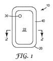
本発明に従う医療用手当て用品の例示的な一実施形態を図1及び2(図2は、図1の線2−2に沿って切り取った断面図である)に示す。医療用手当て用品10は支持体20(好ましくは、本明細書に記載のような柔軟なものであり得る)を含む。支持体20は、2つの反対側の主表面、すなわち、内側表面22及び外側表面24を含む。使用に際して、内側表面22が創傷(又は他の身体部位)に面し、創傷(又は他の身体部位)から見て外側表面24が外側を向くように、医療用手当て用品は創傷(又は他の身体部位)を覆って配置される。
An exemplary embodiment of a medical dressing according to the present invention is shown in FIGS. 1 and 2 (FIG. 2 is a cross-sectional view taken along line 2-2 of FIG. 1). The
支持体20用に潜在的に好適な材料が以下に詳細に記載されるが、機能の点から、支持体20は好ましくは、液体及び急速な気体拡散に対するバリアとして機能する材料から作製される。支持体20のバリア特性は完全なものでも不完全なものでもよく、例えば支持体20は気体の制限された通過を可能にし得るが、支持体20(及び医療用手当て用品10の他の構成要素)は好ましくは、創傷を覆って配置されたときに創傷上の陰圧環境を少なくとも一時的に維持することができるように、気体の通過に対して十分なバリア特性を提供する。例えば、支持体は好ましくは比較的高い水蒸気透過率を有し得るが、液体に対しては実質的に不透過性であることができる。
Although potentially suitable materials for the
医療用手当て用品10は更に通常閉のバルブ30を含み、通常閉のバルブ30は、支持体20を介して形成される1つ以上の経路を覆う支持体20に取り付けられる。支持体20中の1つ以上の経路を通る流量は、バルブ30により制御される。バルブ30(好ましくは、一方向弁)を、陰圧治療を創傷に提供するために使用することができ、創傷を覆って医療用手当て用品10が、本明細書に記載されるように配置される。図1及び図2に示される医療用手当て用品は1つのバルブ30のみを含むが、本発明の医療用手当て用品は、医療用手当て用品によって画定される密閉された環境への追加のアクセスが所望される場合、2つ以上のバルブを含むことができる。
The
医療用手当て用品10にはまた、創傷に内側表面22を向けて、創傷を覆って医療用手当て用品10を患者に接着できるように、内側表面22上に接着剤40を含ませることもできる。接着剤40は、連続的に及び/又はパターンにコーティングする方法で、内側表面22の全体又は一部を覆うことができる。図2に示されるような接着剤40は、接着剤40が支持体20の内側表面22の中央部分の周囲に枠を形成するように、支持体20の周辺又は境界にのみ設けられる。感圧性接着剤を必要とせずに、しっかりと固定されるような医療用手当て用品が挙げられる、他の多くの配置が可能である。例えば、医療用手当て用品は肢周りの外周ラップを含んでもよく、接着剤は必ずしも必要としない。図3に示される1つの配置では、医療用手当て用品10は、接着剤40を創傷Wの周囲の組織(例えば,皮膚)に接着させながら、創傷Wを覆って配置される。創傷W及び創傷の周囲の組織に沿う医療用手当て用品10は、好ましくは密閉された環境を画定し、創傷Wは密閉された環境の中にあることで周囲の環境から隔離される。支持体20の内側表面22を密閉された環境に向けている間、支持体20の外側表面24は創傷Wの外側を向き、創傷は密閉された環境の中に配置される。
The
図1及び2に示されるような接着剤40は、好ましくは支持体20の内側表面22の一部上にのみ露出され得る。図1及び2に示される実施形態では、接着剤40は内側表面22の一部上にのみ設けられる(すなわち内側表面22の中央部分は接着剤40を含まない)。しかしながら他の実施形態では、患者への取り付けのために接着剤の一部だけが露出したままになっているような、他の要素で覆われた接着剤の一部を、内側表面22の実質的に全体を覆って設けられてもよい。
The adhesive 40 as shown in FIGS. 1 and 2 may preferably be exposed only on a portion of the
しかしながら任意の実施形態では、創傷を覆って患者に接着するよう、密閉された環境の境界を支持体20の内側表面22で画定することで、医療用手当て用品10が接着剤40により患者に取り付けられたときに、創傷を覆う密閉された環境を形成できるように、支持体20の全周に接着剤40が連続的に延びることが好ましい場合がある。
However, in any embodiment, the
好適なバルブ30の使用により、好ましくは創傷を覆って取り付けられた医療用手当て用品10によって作り出された、密閉された環境は、密閉された環境と流体連通された能動的な減圧供給源が存在しなくとも、陰圧(すなわち、支持体20の外側表面24上の環境大気圧を下回る圧力)に維持される。
With the use of a
医療用手当て用品を取り外す必要なく、及び密閉された環境内部の陰圧を維持するために流体を持続的に取り除く必要なく、密閉された環境から流体を取り除くために、本発明に関連して使用されるバルブが、1回、2回、又はそれ以上の回数使用できることが好ましい場合がある。例えば、本明細書に記載されるような、流体の除去が終了した時に閉放させることができるバルブを通して、密閉された環境から流体を取り除くことができる。密閉された環境内に更なる流体が蓄積する場合、この蓄積物は本明細書に記載されるようなバルブを通して取り除くことができる。いくつかの実施形態では、密閉された環境に入った流体(例えば、液体)を吸収するために、医療用手当て用品が吸収材料を含むことが好ましい場合がある。潜在的に好適な吸収材料の例としては、限定するものではないが、親水性フォーム、織布、不織布など、及びこれらの組み合わせを挙げることができる。吸収材料が、吸収性であり、かつ密閉された環境にバルブを通して真空が適用されたときに任意の吸収した流体の少なくとも一部(好ましくは、ほとんど)を放出する能力を有するという、これらの両方の性質を備えていることは好ましいものであり得る。密閉された環境からの流体除去時に、吸収した流体を放出することで、吸収材料の流体を吸収する能力を再生し得る(医療用手当て用品の耐用寿命を延ばすことができる)。 Used in connection with the present invention to remove fluid from a sealed environment without having to remove the medical dressing and without having to continually remove the fluid to maintain the negative pressure inside the sealed environment It may be preferred that the valve being used can be used once, twice, or more times. For example, fluid can be removed from the sealed environment through a valve that can be closed when fluid removal is complete, as described herein. If additional fluid accumulates in the sealed environment, this accumulation can be removed through a valve as described herein. In some embodiments, it may be preferred that the medical dressing includes an absorbent material to absorb fluid (eg, liquid) that has entered a sealed environment. Examples of potentially suitable absorbent materials include, but are not limited to, hydrophilic foams, woven fabrics, nonwoven fabrics, and the like, and combinations thereof. Both of these, wherein the absorbent material is absorbent and has the ability to release at least a portion (preferably most) of any absorbed fluid when a vacuum is applied through a valve in a sealed environment It may be preferable to have the following properties. By releasing the absorbed fluid upon removal of the fluid from the enclosed environment, the absorbent material's ability to absorb the fluid can be regenerated (the useful life of the medical dressing can be extended).
医療用手当て用品10によって密閉された環境において維持される陰圧の程度は、典型的には経時的に(密閉された環境からバルブ30を通しての流体の能動的な除去の間に最高値に達した後に)低下するが、医療用手当て用品10が少なくともある程度の有意な期間にわたって陰圧を維持する能力を有することが好ましい場合もある。いくつかの実施形態においては、医療用手当て用品10が、1分以上、5分以上、10分以上、15分以上、30分以上、又は更には60分以上にわたって、密閉された環境において(能動的な減圧供給源が存在しなくとも)少なくともある程度の陰圧を維持できることが好ましい場合もある。
The degree of negative pressure maintained in the sealed environment by the
医療用手当て用品10によって画定された密閉された環境内部の陰圧の低下は、様々な原因により生じ得る。例えば低下の一部は、支持体20及び/又は支持体20を患者に取り付けている接着剤40を通っての、密閉された環境への気体の拡散によるものである場合がある。密閉された環境における陰圧低下の他の原因は、患者からの(創傷自体及び/又は創傷の周囲の組織による)気体及び/又は液体が、密閉された環境に入ることによってもたらされる場合がある。
The reduction in negative pressure within the sealed environment defined by the
いくつかの実施形態では、密閉された環境内部の陰圧の持続性は、密閉された環境内へのバラスト要素の添加によって高められ得る。バラスト要素は、例えば密閉された環境内に提供された真空(陰圧)に応じて圧縮されるか又は縮む、弾性的に圧縮できる物質であり、その弾性によって少なくとも部分的には圧縮前の大きさに戻るよう企図される。例えば、バラスト要素は弾性フォーム(連続気泡型又は独立気泡型であるが、好ましくは連続気泡型)、不織布、バネ、又は圧縮することができる他の構成であってよいが、少なくとも部分的には圧縮前の大きさに戻ることが企図されるように、弾性的でもある(例えば、弾性物質はバネ定数を有する)。 In some embodiments, the persistence of negative pressure within a sealed environment can be increased by the addition of ballast elements within the sealed environment. A ballast element is an elastically compressible material that is compressed or contracted in response to, for example, a vacuum (negative pressure) provided in a sealed environment, and at least partly before compression due to its elasticity. It is intended to return. For example, the ballast element may be an elastic foam (open-celled or closed-celled but preferably open-celled), non-woven, spring, or other configuration that can be compressed, but at least in part. It is also elastic, as is contemplated to return to its pre-compression magnitude (eg, an elastic material has a spring constant).
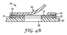
図1〜3に示されるような医療用手当て用品10に使用することができる、バルブ30の1つの例示の実施形態を、図4A〜4Cに見ることができる。このバルブは、本発明に関連して使用できる、潜在的に好適なバルブの一実施形態を表すが、図4A〜4Cに示される具体的なバルブ構成の代わりに、多くの他のバルブを使用することもできる。
One exemplary embodiment of a
図4A〜4Cのバルブ30は、支持体20を通して形成される単一開口部26を覆って配置されているように示されるが、バルブ30は開口部への流量を制御するために、2つ以上の開口部を覆って配置されてもよい。本明細書で述べるようなバルブ30及び開口部26は、好ましくは排出ポートを提供することができ、流体はこのポートを通って支持体20を通過できる。バルブ30は、支持体20に取り付けられた基層32及び基層32に取り付けられたフラップ層34を、基層32がフラップ層34と支持体20の間に配置されるように含む。
Although the
基層32は、任意の適した技術又は技術の組み合わせ(例えば、接着、ヒートシール、化学溶着、熱溶着、超音波溶接など)により、支持体20に取り付けることができる。示された実施形態では、基層32は接着剤31を用いて支持体20に取り付けられる。フラップ層34は、任意の適した技術又は技術の組み合わせ(例えば、接着、ヒートシール、化学溶着、熱溶着、超音波溶接など)により、基層32に取り付けることができる。示された実施形態では、フラップ層34は、好ましくは基層32とフラップ層34の外周に配置することができる接着剤33により、基層32に取り付けることができる。バルブ30はまた、バルブフラップ36が閉止した配置にあるときに、バルブフラップ36が置かれるのに備えて、所望により、基層32の領域上に配置された接着剤37を含むこともできる。配置された接着剤37は、好ましくは本明細書で述べるようなバルブ30を開放させるために、制限された粘着性を有するが、この粘着性は、閉止形状にあるときのバルブ30の配置も改善し得る。
The base layer 32 can be attached to the
フラップ層34は、フラップ層34のバルブフラップ36の形状を画定するスリット35を含む。好ましくはバルブフラップ36は、流体が開口部26を自由に通過できないように、開口部26を閉止するために、支持体20の開口部26を覆って配置されるバルブフラップ36内に、閉止形状を有し得る(図4Aを参照されたい)。存在する場合、配置した接着剤37は、バルブ30の密閉を補助し得る。好ましくはバルブフラップ36は、図4Aの閉止形状から、流体が開口部26及びバルブ30を通過できる開放形状(図4Bに示される)へと、バルブ30を変形させるために可動性である。
The
バルブ30の、開放形状及び閉止形状間の変形は、好ましくは選択的に実施されるが、バルブ30を開放できる力が適用されない場合にはバルブ30が閉止しているよう、バルブ30が通常閉であることが好ましい場合がある。いくつかの実施形態では、バルブ30は、バルブ30の内外に(すなわち、支持体20の内側表面22から外側表面24にかけて)生成される圧力差により開放されてもよい。例えば、バルブフラップ36は、内側表面22と同じ方向に向くバルブ30側上の流体圧力が、バルブフラップ36上に作用するバルブフラップ36を閉止している形状に保持しようとする力よりも十分に大きい場合に、開放されてもよい。バルブ30が閉止形状から開放形状へと動く圧力差は、「クラッキング圧」と呼ばれる。
The deformation of the
バルブ30の内外の圧力差は、例えば、ポンプの入口(例えば、真空ポンプ)、又は裏材20の外部表面24上の弁30の外部表面を覆うポンプの入口に通じる流体導管(例えば、チューブ、ホースなど)に圧力を適用することによって達成することができる。好ましくはポンプは、バルブ30の内外に(すなわち、支持体20の内側表面22及び外側表面24の間で)生成される圧力差が、クラッキング圧に達するのに十分高いものであるよう、バルブ30の外側上に減圧環境を提供する能力を有するものである。一度バルブ30が開放形状になると、医療用手当て用品10により創傷を覆って画定された密閉環境中の流体(気体及び/又は液体)は、開口部26及びバルブ30を通して取り除かれてもよい。密閉された環境から取り除かれた流体は、固体粒子を含有していても、含有していなくてもよい。
The pressure difference inside and outside the
必要ではないが、好ましくは流体除去は、本明細書で述べるような陰圧にある密閉された環境に置かれるが、このような条件は必ずしも必要とされない。例えば流体除去は、密閉された環境内に陰圧条件をもたらす必要なく、密閉された環境等から創傷滲出物、血液などの流体を取り除くことに制限される場合もある。 Although not required, preferably fluid removal is placed in a sealed environment at negative pressure as described herein, although such conditions are not necessarily required. For example, fluid removal may be limited to removing fluids such as wound exudates and blood from a sealed environment or the like without having to create negative pressure conditions within the sealed environment.
図4A〜4Cに示されるバルブ30は、本発明に関連して使用されてもよい、潜在的に好適なバルブの単なる一例である。他の潜在的に好適なバルブの一部の例を、図5A〜5Cに示す。
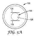
The
図4A〜4Cのバルブ30は、単一の連続的なスリット35により形成されるバルブフラップ36を含むが、バルブフラップを、図5Aに示されるような複数のスリットによっても形成できる。バルブ130は、フラップ層134のスリット135によって形成された、バルブフラップ136を含む。好ましくはスリット135は、バルブ130が配置された支持体120内の開口部126を流体が通過できるようにするために、バルブフラップ136を基層132から離して持ち上げさせる。図5Bは、基層132に接触して配置されたバルブフラップ136を備える、閉止形状にあるバルブ130を示し、一方、図5Cは、スリット135に沿って形成される開口部を流体が通過することができるように、基層132から分離されたバルブフラップ136を備える、開放形状にあるバルブ130を示す。
4A-4C includes a
それぞれ単一のバルブフラップを含むバルブ30及びバルブ130を上記したが、別の方法としては、本発明に関連して使用されるバルブには、2つ以上のバルブフラップを含ませることができる。図6A及び6Bに、流体に各々開口部226及び開口部326を通過させるために開放する複数のバルブフラップ236及びバルブフラップ336を、バルブ230及びバルブ330のそれぞれが含んでいる、2つの潜在的に好適な実施例の例を示す。
Although
図4A〜4C、5A〜5C及び6A〜6Bと関連して上記される種類のバルブは、複数の高分子フィルム層から構成されるものとして特徴付けることができる。かかるバルブに使用される高分子フィルム層が可撓性の高分子フィルムであることが、更に好ましい場合もある。追加的な機構及び変更、並びに上記されたようなバルブを製造する各種の方法を、米国特許出願公開第US2006/0228057号(Newrones et al.)に見出すことができる。 Valves of the type described above in connection with FIGS. 4A-4C, 5A-5C, and 6A-6B can be characterized as being composed of a plurality of polymeric film layers. It may be more preferred that the polymer film layer used in such a valve is a flexible polymer film. Additional mechanisms and modifications, as well as various methods of manufacturing valves as described above, can be found in US Patent Application Publication No. US 2006/0228057 (Newrones et al.).
更に、具体的に本明細書に記載されたバルブの代わりに、又はそれに追加して、多くの他のバルブを使用することができる。例えば、「Goglio」型又は「Raackmann」型のバルブとして既知のもののようなバルブを、本発明に関連して使用してもよい。Goglio型のバルブは、例えばBosch、Wipf及びWicoから入手可能であり、Raackmann型のバルブは、例えばAmcorから入手可能である。他の潜在的に好適なバルブとしては、ダックビル型又はアンブレラ型のバルブ(これらの例は、Vernay Laboratories,Inc.,Yellow Springs,Ohioから入手可能なものである)を挙げることができる。好適な真空弁の更に他の例としては、米国特許第6,913,803号、同第6,733,803号、同第6,607,764号、及び同第6,539,691号に記載のものが挙げられ、これらの特許のそれぞれは、その全文が参照として本明細書に組み込まれる。 In addition, many other valves can be used in place of or in addition to the valves specifically described herein. For example, valves such as those known as “Goglio” type or “Raackmann” type valves may be used in connection with the present invention. Goglio type valves are available, for example, from Bosch, Wipf and Wico, and Raackmann type valves are available, for example, from Amcor. Other potentially suitable valves may include duckbill or umbrella type valves (examples are available from Vernay Laboratories, Inc., Yellow Springs, Ohio). Still other examples of suitable vacuum valves include those disclosed in U.S. Patent Nos. 6,913,803, 6,733,803, 6,607,764, and 6,539,691. Each of these patents is incorporated herein by reference in its entirety.
本明細書で記載されるように、快適性を改善し、外力(例えば、寝具、衣類など)によるずれに対する耐性を向上させるために、バルブの外形又は高さが制限されることが好ましい場合がある。 As described herein, it may be preferable to limit the outer shape or height of the valve to improve comfort and to improve resistance to slippage due to external forces (eg, bedding, clothing, etc.). is there.
1つの方法としては、本発明の医療用手当て用品に関連して使用される薄型のバルブは、通常は支持体の主表面について測定されるような、バルブ構成の最大厚さに関して特徴付けることができる(ここで支持体の主表面とは、内側表面及び外側表面である)。例えば、本発明の医療用手当て用品に使用されるバルブが、1センチメートル(cm)以下の、いくつかの実施形態では5ミリメートル(mm)以下の、いくつかの実施形態では3ミリメートル(mm)以下の、又は更には2mm以下の、及びより好ましくは1mm以下(例えば、更には200マイクロメートル(μm)以下)の、最大厚さを有することが好ましい場合がある。 As one method, the thin valve used in connection with the medical dressing of the present invention can be characterized with respect to the maximum thickness of the valve configuration, as usually measured for the major surface of the support. (Here, the main surface of the support is the inner surface and the outer surface). For example, the valves used in the medical dressings of the present invention may be 1 centimeter (cm) or less, in some embodiments 5 millimeters (mm) or less, and in some embodiments 3 millimeters (mm). It may be preferred to have a maximum thickness of less than or even 2 mm or less, and more preferably 1 mm or less (eg, even less than 200 micrometers (μm)).
他の方法においては、本発明に関連して使用される低い外形のバルブは、通常閉のバルブと支持体との間の死容量の形態について特徴付けることができる。本明細書で使用されるように、用語「死容量」は、バルブが通常閉の形状にあるときに、流体がバルブと支持体の内側表面との間に蓄積し得る容量又は空間を表す。通常閉のバルブと支持体の内側表面との間の死容量を減ずることは、バルブ及び医療用手当て用品全体の外形を減ずるのに役立ち得る。 In other methods, the low profile valve used in connection with the present invention can be characterized for the form of dead volume between the normally closed valve and the support. As used herein, the term “dead volume” refers to the volume or space in which fluid can accumulate between the valve and the inner surface of the support when the valve is in a normally closed configuration. Reducing the dead volume between the normally closed valve and the inner surface of the support can help reduce the overall profile of the valve and the medical dressing.
例えば、図4A〜4Cに記載されるバルブ30は、死容量すなわち、支持体20の厚さと支持体20に占める開口部26の面積とによって本質的に画定される空間(内側表面22と外側表面24の間)を画定する。この実施形態では、フラップ層34のバルブフラップ36が、基層32を介して支持体20の外側表面24から離れていることから、死容量は基層32の厚さ分だけ更に増加する。
For example, the
本発明の医療用手当て用品において、通常閉のバルブと支持体とで画定される死容量は、好ましくは200立方ミリメートル(mm3)以下、100mm3以下、50mm3以下、10mm3以下、いくつかの実施形態では6mm3以下、又は更には4mm3以下、加えていくつかの実施形態では更に2mm3以下(例えば、1mm3以下)であり得る。通常閉のバルブにより画定される死容量は、例えば、バルブ本体に水を充填して死容量を測定することにより、直接判定することができる。あるいは、死容量を直接測定することが困難である場合には、死容量はバルブの死容量内に適合する別個の機構を参考にして測定してもよく、この場合、水の容量の測定は別個の機構に代えられる。したがって、バルブの死容量は、図のようにバルブの死容量について適合するカテーテルハブなどのような別個の機構を用い、水中にハブを浸して液体量移動を計測することにより、10mLのメスシリンダー内の液体量移動から概算することができる。 In the medical dressing of the present invention, the dead volume defined by the normally closed valve and the support is preferably 200 cubic millimeters (mm 3 ) or less, 100 mm 3 or less, 50 mm 3 or less, 10 mm 3 or less, several In embodiments, it may be 6 mm 3 or less, or even 4 mm 3 or less, and in some embodiments, 2 mm 3 or less (eg, 1 mm 3 or less). The dead volume defined by the normally closed valve can be determined directly, for example, by filling the valve body with water and measuring the dead volume. Alternatively, if it is difficult to directly measure the dead volume, the dead volume may be measured with reference to a separate mechanism that fits within the dead volume of the valve, in which case the measurement of the volume of water is It is replaced by a separate mechanism. Therefore, the dead volume of the valve can be measured by using a separate mechanism such as a catheter hub that matches the dead volume of the valve as shown in the figure, and measuring the amount of liquid movement by immersing the hub in water. It can be estimated from the movement of the amount of liquid inside.
減圧下でつぶれることを防ぐために、接続部分は比較的に堅くなければならないことから、好ましくはバルブ30はポートあるいはチューブ接続部に組み込まれない。これらの堅い構成は、患者が創傷の上に横になったとき(例えば、ベッドにいるときに)に、圧迫部分をもたらし得る。
Preferably,
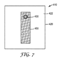
本発明の医療用手当て用品のいくつかの実施形態に含まれ得る他の所望の機構はスタンドオフ要素であり、これは支持体の内側表面上のバルブの近傍に配置され、密閉された環境からの流体の除去を補助し得る。図7は、医療用手当て用品410の支持体420の内側表面422の平面図である。医療用手当て用品410は、内側表面422全体(スタンドオフ要素450によって占められる面積は除く)にわたって露出される接着剤も含み得る。接着剤は、連続的に又はパターンでコーティングしてもよいが、コーティング法には関係なく、密閉された環境内に陰圧を得ることができるような、気密密閉を提供できる接着剤が好ましいものであり得る。パターンにコーティングされた接着剤に関して、潜在的に好適なパターンの一例は、格子パターンである場合がある。バルブ430が、支持体420内のスタンドオフ要素450によって占められる領域内部に配置されることが好ましい場合があるが、いくつかの実施形態では、バルブ430はスタンドオフ要素450の周辺近傍に配置されてもよい。
Another desired mechanism that may be included in some embodiments of the medical dressing of the present invention is a standoff element, which is located near the valve on the inner surface of the support and from a sealed environment. Removal of the fluid. FIG. 7 is a plan view of the
スタンドオフ要素450は、医療用手当て用品410によって画定される密閉された環境内の流体を、バルブ430を介して取り除くことができるように、流体経路の開口をもたらす何らかの形態の構造を、1つ以上の表面上に含む。例えば、スタンドオフ要素450を設けないで、医療用手当て用品410の内側表面422を創傷又は創傷周囲の皮膚に対して密閉させた場合、密閉された環境からのバルブ430を介しての流体の除去が妨げられる場合がある。しかしながら、スタンドオフ要素450は、好ましくは、密閉された環境が大気に対して陰圧にある場合でさえも、バルブ430を通した流体除去を促進するために開口流体経路を維持することができ、すなわち流体経路は好ましくはつぶれることに耐性がある(陰圧下でさえも)。
The
図7に示された医療用手当て用品は、1つのスタンドオフ要素450及び1つのバルブ430のみしか含んでいないが、本発明の医療用手当て用品は、例えば同じスタンドオフ要素に関連する2つ以上のバルブを含むこともできる。複数のバルブの使用が有益である場合もある(例えば、密閉された環境、機能不全、詰まりなどに対して、1つのバルブでは配置が不十分である場合)。他の変形形態では、本発明の医療用手当て用品は2つ以上のスタンドオフ要素を含んでもよく、スタンドオフ要素のそれぞれは、密閉された環境からの流体除去を促進するために、1つ以上のバルブに関連付けられ得る。医療用手当て用品と接続されている、2つ以上のスタンドオフ要素の使用が有益である場合もある(例えば、密閉された環境、詰まりなどに対して、1つのスタンドオフ要素では配置が不十分である場合)。
Although the medical dressing shown in FIG. 7 includes only one
本発明の医療用手当て用品に使用されるスタンドオフ要素は、様々な形態をとることができる。いくつかの実施形態では、スタンドオフ要素を支持体の内側表面に直接形成することができる(例えば、エンボス加工、研磨加工、成型加工、切り取り加工などにより)。他の実施形態では、スタンドオフ要素は、チャネル、あるいはエンボス加工、研磨加工、成型加工、切り取り加工ないしは別の方法でその内部に形成された他の構成を有する、別個の物品(例えばフィルムなど)の形態をとる。スタンドオフ要素を形成する別個の物品は、好ましくは、任意の好適な技術又は技術の組み合わせによって、支持体に取り付けられる(例えば、接着剤、ヒートシール、熱溶着など)。 The standoff element used in the medical dressing of the present invention can take a variety of forms. In some embodiments, the standoff element can be formed directly on the inner surface of the support (eg, by embossing, polishing, molding, cutting, etc.). In other embodiments, the stand-off element is a separate article (e.g., film, etc.) having a channel or embossing, polishing, molding, cutting, or other configuration formed therein otherwise. Takes the form of The separate articles that form the standoff elements are preferably attached to the support (eg, adhesive, heat seal, heat weld, etc.) by any suitable technique or combination of techniques.
スタンドオフ要素内のチャネルは、限定するものではないが、ハニカムパターンのチャネル、格子又は部分的に格子のチャネル、溝の連続(例えば、平行な溝の連続、放射状の溝の連続)であるチャネル、柱状(posts)又は他の別個の構成(例えば、角錐など)にあるチャネル、などの任意のパターン又は形状のチャネルであってもよい。場合によっては、スタンドオフ要素が医療用手当て用品の支持体とは別個の物品として提供される場合、物品は、スタンドオフ要素の両方の主要な側面上に流体経路形成構造を含んでもよい。両面スタンドオフ要素550の1つの例示的な実施形態が図8に示され、主要側面551及び主要側面553の両方に形成される両面スタンドオフ要素550は、(各々)チャネル552及びチャネル554を含む。いくつかの潜在的に好適なスタンドオフ要素の例を、例えば米国特許出願公開第US2007/0172157号(Buchman)、米国特許第6,420,622号(Johnston et al.)などに更に述べることができる。
The channels in the standoff element include, but are not limited to, channels in honeycomb pattern, grids or partially grid channels, channels that are a series of grooves (eg, a series of parallel grooves, a series of radial grooves). , Channels in any pattern or shape, such as channels in posts or other separate configurations (eg, pyramids, etc.). In some cases, when the standoff element is provided as an article separate from the support of the medical dressing, the article may include a fluid path forming structure on both major sides of the standoff element. One exemplary embodiment of a double-
本発明の医療用手当て用品に含ませることができる他の所望の要素は、医療用手当て用品のバルブ近傍に配置させることができるバリア要素である。バリア要素は、好ましくは、創傷滲出物から、バルブを別段に汚染させ得る物質を濾過するために機能させることができ、このようなバルブは、医療用手当て用品によって画定された密閉された環境から流体を取り除いた後に、再閉止又は密閉しない。バリア要素は医療用手当て用品(医療用手当て用品の支持体の内側表面近傍に)に取り付けて提供することができ、又はバリア要素は、患者に医療用手当て用品を送達するときに配置させることができるような、取り付けられていない形態で、医療用手当て用品と共に提供することができる。バリア要素によって濾過され得る、幾種類かの物質の例としては、例えば凝固した血液、遊離した組織、組織充填物などを挙げることができる。 Another desired element that can be included in the medical dressing of the present invention is a barrier element that can be placed near the valve of the medical dressing. The barrier element is preferably capable of functioning to filter substances from the wound exudate that can further contaminate the valve, such a valve from the sealed environment defined by the medical dressing. Do not reclose or seal after removing fluid. The barrier element can be provided attached to a medical dressing (near the inner surface of the medical dressing support) or the barrier element can be placed when delivering the medical dressing to the patient. It can be provided with the medical dressing in an unattached form as is possible. Examples of some types of substances that can be filtered by the barrier element can include, for example, clotted blood, free tissue, tissue filling, and the like.
バリア要素は、各種異なる材料を用いて設けられてもよい。バリア要素用に潜在的に好適な材料の幾種類かの例としては、例えば布地(例えばガーゼ、不織布、織布、編布など)、発泡対などを挙げることができる。バリア要素にはまた、潜在的には、例えばヒドロゲル、ヒドロコロイドなどの吸収材料を組み込むこともできる。いくつかの実施形態では、バリア要素は、本明細書に記載されるような密閉された環境内の陰圧の維持を補助するために、所望により、バリア要素をバラスト要素としても機能させることもできるよう、弾性的に圧縮可能であってもよい。 The barrier element may be provided using a variety of different materials. Some examples of potentially suitable materials for the barrier element can include, for example, fabrics (eg, gauze, nonwovens, wovens, knitted fabrics, etc.), foam pairs, and the like. The barrier element can also potentially incorporate absorbent materials such as hydrogels, hydrocolloids and the like. In some embodiments, the barrier element may also function as a ballast element, if desired, to help maintain negative pressure in a sealed environment as described herein. It may be elastically compressible so that it can.
いくつかの実施形態では、バリア要素の代わりに、又はバリア要素に加えて、医療用手当て用品に創傷充填材を設けることもできる。いくつかの実施形態では、創傷充填材はまた、本明細書に記載のようなバリア要素としても機能し得る(この機能は必須ではない)。いくつかの実施形態では、創傷充填材は、本明細書に記載されるような密閉された環境内の陰圧の維持を補助するために、所望により、創傷充填材をバラスト要素としても機能させることもできるように、弾性的に圧縮できるものであってもよい。創傷充填材は、例えば、密閉された環境内に収容された創傷が、著しい陥没の形態の、慢性的創傷である(場合によっては周囲の皮膚の下に空洞を形成する)場合に有用であり得る。このような創傷を治療する場合、密閉された環境を作り出すために医療用手当て用品を創傷を覆って適用する前に、創傷に創傷充填材を設けることが、望ましいものであり得る。 In some embodiments, a wound dressing can be provided in the medical dressing instead of or in addition to the barrier element. In some embodiments, the wound filler may also function as a barrier element as described herein (this function is not essential). In some embodiments, the wound filler also functions as a ballast element, as desired, to help maintain negative pressure in a sealed environment as described herein. It may be one that can be elastically compressed. Wound filler is useful, for example, when the wound housed in a sealed environment is a chronic wound (possibly forming a cavity under the surrounding skin), in the form of significant depression. obtain. When treating such wounds, it may be desirable to provide a wound filler on the wound prior to applying a medical dressing over the wound to create a sealed environment.
創傷充填物は、好ましくは創傷の形状に充填できるように、及び/又はぴったり一致できるように、可撓性であってもよい。創傷充填物は、好ましくは吸収性であっても非吸収性であってもよい。創傷充填物は、好ましくはその中を流体が通過できる通路を提供することができるものであり得る。創傷充填材のいくつかの潜在的に好適な例としては、創傷に設置されて内部容積を充填し得る、完全な又は部分的な網状発泡体(例えば、開放気泡ポリウレタン発泡材など)、布地(例えば、ガーゼ、織布、編布)、又は不織布材)、粒子状物質などを挙げることができる。いくつかの実施形態では、粒子状の形態で提供される場合に、創傷充填物を取り除きやすくするために、粒子を可撓性のバッグ又は他の構成に収容してもよい(例えば、創傷充填材が生体吸収性及び/又は生分解性でない限りは)。 The wound filling may be flexible, preferably so that it can fill the wound shape and / or closely match. The wound filling may preferably be absorbable or non-absorbable. The wound filler may preferably be capable of providing a passage through which fluid can pass. Some potentially suitable examples of wound fillers include full or partial reticulated foams (such as open cell polyurethane foams), fabrics (such as open cell polyurethane foams) that can be placed on the wound to fill the interior volume. For example, gauze, woven fabric, knitted fabric) or non-woven fabric material), particulate matter, and the like can be mentioned. In some embodiments, the particles may be contained in a flexible bag or other configuration to facilitate removal of the wound filler when provided in particulate form (eg, wound filling). Unless the material is bioabsorbable and / or biodegradable).
バリア要素及び/又は創傷充填材が医療用手当て用品に取り付けられていないような形態で設けられる場合、医療用手当て用品は、医療用手当て用品並びに別個のバリア要素及び/又は創傷充填物を含む、キットの形態で提供することもできる。バリア要素及び/又は創傷充填物は、このようなキットの使用時に、医療用手当て用品を患者に送達する前に、医療用手当て用品に取り付けることができる。別の方法としては、バリア要素及び/又は創傷充填物を配置した後に、医療用手当て用品を創傷を覆って設置することで、バリア要素及び/又は創傷充填物を創傷上に又は創傷の中に配置することができる。 Where the barrier element and / or wound filler is provided in a form that is not attached to the medical dressing, the medical dressing includes the medical dressing and a separate barrier element and / or wound filler; It can also be provided in the form of a kit. The barrier element and / or wound filler can be attached to the medical dressing prior to delivering the medical dressing to the patient during use of such a kit. Alternatively, after placing the barrier element and / or wound filler, a medical dressing is placed over the wound to place the barrier element and / or wound filler on or in the wound. Can be arranged.
本発明の医療用手当て用品は、陰圧創傷閉鎖法を提供するために使用することができるが、場合によっては、流体又は他の物質を、密閉された環境中に医療用手当て用品を通して送達できるようなものであり得る。例えば、ピペット、針などの送達デバイスは、医療用手当て用品の支持体を貫通させて、密閉された環境中に送達デバイスを介して流体又は他の物質を送達するために、使用されてもよい。密閉された環境中への、医療用手当て用品を通しての物質の送達が、本明細書に記載のような密閉された環境を画定するという医療用手当て用品の能力を機能的に損なわないことは、好ましいものであり得る。 The medical dressing of the present invention can be used to provide a negative pressure wound closure method, but in some cases, fluids or other substances can be delivered through the medical dressing in a sealed environment. It can be like that. For example, delivery devices such as pipettes, needles, etc. may be used to penetrate the support of medical dressings and deliver fluids or other substances through the delivery device into a sealed environment. . Delivery of a substance through a medical dressing into a sealed environment does not functionally impair the ability of the medical dressing to define a sealed environment as described herein. It may be preferred.
再密閉可能なアクセスを、密閉された環境に医療用手当て用品を通して提供するために、医療用手当て用品支持体に使用される材料は、例えば支持体を通して形成された開口部が、送達デバイスの取り外しに応じて密閉する(例えば、隔膜の方式で)ように、自己密閉することができる。他の例では、送達デバイスを取り外した後、送達デバイスによって支持体を通して形成される、任意の開口部を閉放するために、閉止要素を医療用手当て用品支持体の外側表面を覆わせて提供することができる。 In order to provide resealable access through a medical dressing in a sealed environment, the material used for the medical dressing support may be, for example, an opening formed through the support that is removed from the delivery device. Can be self-sealing, such as in the form of a diaphragm. In other examples, after removing the delivery device, a closure element is provided over the outer surface of the medical dressing support to close any openings formed through the support by the delivery device. can do.
図9は、本発明の医療用手当て用品の支持体520に取り付けられた1つの潜在的な閉止要素580の断面図である。本明細書で述べるような閉止要素580は、好ましくは、密閉された環境へのアクセスを提供するために作製された開口部を覆って、支持体520に取り付けられる。閉止要素580は、好ましくは、感圧接着剤582を使用して支持体520に取り付けられてもよい。
FIG. 9 is a cross-sectional view of one
使用前に任意の閉止要素580を医療用手当て用品に取り付けてもよく、すなわち、閉止要素580は支持体520(又は医療用手当て用品のなんらかの他の部分)へとあらかじめ取り付けることができる。あらかじめ取り付けられた場合には、次いで閉止要素580をその開始位置から取り外し、そして密閉された環境へのアクセスを提供するために支持体520を通して作製された開口部を覆って、再び取り付けることができる。
An
いくつかの実施形態では、閉止要素は、閉止要素が取り除かれるか、ないしは別の方法で開放されるまでバルブが閉止要素により密閉されて閉じられているように、バルブを覆って医療用手当て用品の外側表面に取り付けることができる。1つのこのような実施形態を図10に示す。図10では、閉止要素680は、バルブ630を囲む支持体620の外側表面624に取り付けられる。
In some embodiments, the closure element covers the valve and the medical dressing so that the valve is sealed and closed by the closure element until the closure element is removed or otherwise opened. Can be attached to the outer surface of the. One such embodiment is shown in FIG. In FIG. 10, the
閉止要素680は、接着、ヒートシール、溶着、キャスティングなどを用いて取り付けられてもよいが、バルブ630を覆うその配置から取り外した後に、医療用手当て用品に再び取り付けることができるように、感圧接着剤を用いて取り付けられた閉止要素680が好ましいものであり得る。このような実施形態では、閉止要素680は、潜在的にはバルブ630を覆って医療用手当て用品に再び取り付けることでバルブ630を再密閉することができ、及び/又は閉止要素680は、支持体620を通して作製された開口部(例えば、本明細書に記載の密閉された環境に物質を送達するために)を密閉するために、医療用手当て用品上の他の場所に取り付けることもできる。
閉止要素を、支持体620の外側表面に取り付けられるものとして示し、記載したが、閉止要素680は、単にバルブ630(医療用手当て用品全体の外側表面と本質的に等価である)の外側表面に取り付けられてもよいということは理解されるべきである。
Although the closure element is shown and described as being attached to the outer surface of the
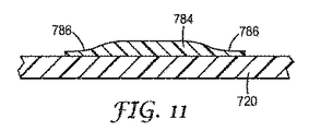
更に他の実施形態では、密閉された環境への医療用手当て用品を通しての再密閉可能なアクセスを提供するために、隔膜要素(例えば、隔膜)を医療用手当て用品支持体に取り付けることができる。図11は、本発明の医療用手当て用品の支持体720に取り付けられた、1つの潜在的な隔膜要素784の断面図である。本明細書で述べるような隔膜要素784は、密閉された環境へのアクセスを提供するために作製された再密閉可能な開口部を通した配置を提供するために、好ましくは支持体720に取り付けられる。隔膜要素784は好ましくは、より厚い中央部分と、より厚い中央部分からの段階的な遷移を提供する先細り端部786とを有してもよい。
In still other embodiments, a diaphragm element (eg, a diaphragm) can be attached to a medical dressing support to provide resealable access through the medical dressing to a sealed environment. FIG. 11 is a cross-sectional view of one
隔膜要素(又は複数の要素)784を、支持体720の内側表面及び/又は外側表面上に配置することができる。隔膜要素784は好ましくは、任意の好適な技術(例えば、接着、ヒートシール、溶着、一体成型など)、又はこれらの技術の組み合わせを用いて支持体720に取り付けることができる。
A diaphragm element (or elements) 784 can be disposed on the inner and / or outer surface of the
医療用手当て用品は1つ以上の隔膜要素を含むことができる。いくつかの実施形態では、隔膜要素は、単に支持体の片面だけに又は支持体の両面に見出すことができる。更に他の実施形態では、1対以上の隔膜要素は、互いに反対向きに、直接、支持体の内側表面と外側表面の両面に配置されてもよい。 The medical dressing can include one or more diaphragm elements. In some embodiments, the diaphragm element can be found on only one side of the support or on both sides of the support. In still other embodiments, the one or more pairs of diaphragm elements may be disposed on opposite sides of the support directly and oppositely on opposite sides of each other.
使用前に隔膜要素784を医療用手当て用品に取り付けてもよく、すなわち、隔膜要素784は支持体720(又は医療用手当て用品のどこか他の部分)へとあらかじめ取り付けられてもよい。他の実施形態においては、隔膜要素784は別個に(すなわち支持体720に取り付けずに)設けられてもよく、したがって、エンドユーザが隔膜要素784を支持体720上の選択された位置に配置できるようにする(例えば、医療用手当て用品を所望の場所へと接着させる、感圧接着剤でコーティングされた弾性の隔膜として)。
The
血管にアクセスするカテーテルと類似のチューブを挿入することによって、隔膜を通して流体を送達することが想到される(この場合、カテーテルは先のとがっていない針又は導入装置の補助により、隔膜を通して挿入され、これは続いて相対的に可撓性のカテーテルチューブの先のとがっていない末端を残して取り除かれる)。この方法では、患者を傷つける恐れのある場所には、針はとどまらない。 It is envisaged to deliver fluid through the septum by inserting a tube similar to a catheter that accesses the blood vessel (in which case the catheter is inserted through the septum with the aid of a non-pointed needle or introducer, This is subsequently removed leaving the pointed end of the relatively flexible catheter tube). In this way, the needle does not stay where it can hurt the patient.
密閉された環境に医療用手当て用品を通して送達される流体には、気体(例えば、酸素、一酸化窒素、オゾンなど)及び/又は液体(例えば、生理食塩水、水など)を挙げることができる。場合によっては、粒子もまた、密閉された環境に送達されてもよい(例えば、密閉された環境に送達される流体内に粒子が混入されている場合)。 Fluids delivered through a medical dressing to a sealed environment can include gases (eg, oxygen, nitric oxide, ozone, etc.) and / or liquids (eg, saline, water, etc.). In some cases, the particles may also be delivered to a sealed environment (eg, when the particles are entrained in a fluid delivered to the sealed environment).
場合によっては、密閉された環境(ひいては医療用手当て用品によって覆われた創傷)に1つ以上の活性薬剤を送達することが望ましい場合がある。活性薬剤は、流体として提供し得る、及び/又は内部溶液に送達される流体内で保有され得る。いくつかの潜在的に適切な活性薬剤は、例えば、抗菌生物材、抗菌剤、鎮痛剤、ビタミン等の回復要因、成長因子、栄養素等を含み得る。他の潜在的に適切な薬剤の例は、米国特許第6,867,342号に記載のものであり得る。 In some cases, it may be desirable to deliver one or more active agents to a sealed environment (and thus a wound covered by a medical dressing). The active agent can be provided as a fluid and / or retained within a fluid that is delivered to an internal solution. Some potentially suitable active agents may include, for example, antimicrobial biomaterials, antimicrobial agents, analgesics, recovery factors such as vitamins, growth factors, nutrients, and the like. Examples of other potentially suitable agents may be those described in US Pat. No. 6,867,342.
送達される場合、活性薬剤は密閉された環境へと連続的に又は断続的に供給され得る。例えば、活性薬剤は、密閉された環境へと送達することができ、かつ選択された期間(例えば、数時間)にわたって所定の位置に留め(すなわち、内在させ)、続いて例えば第2の活性薬剤の送達、陰圧治療の送達などを行うことが可能である。最初の活性薬剤は、第2の薬剤の送達前に除去することが可能であるか、又は定置に残留することが可能である。あるいは、密閉された環境は、陰圧条件に配置される前、あるいは第2の薬剤を送達する前などに、例えば、生理食塩水又は他の洗浄液ですすぐこともできる。 When delivered, the active agent can be delivered continuously or intermittently to a sealed environment. For example, the active agent can be delivered to an enclosed environment and stays in place (ie, is inherent) for a selected period of time (eg, several hours), followed by, for example, a second active agent Delivery, negative pressure therapy delivery, and the like. The first active agent can be removed prior to delivery of the second agent or can remain in place. Alternatively, the sealed environment can be rinsed with, for example, saline or other washing solution, such as before being placed in negative pressure conditions or before delivering the second drug.
本明細書で述べるような本発明の医療用手当て用品は、医療用手当て用品によって画定された密閉された環境から、流体を中に通して取り除くことができるバルブを、医療用手当て用品に提供することによって、陰圧創傷閉鎖法のために使用されてもよい。流体は、好ましくは医療用手当て用品に定期的に取り付けることができるポンプによって、密閉された環境からバルブを通して取り除かれる。ポンプが、医療用手当て用品の支持体の外側表面を密閉して液密な密閉を提供することができるシートを含むことが好ましい場合がある。 The medical dressing of the present invention as described herein provides the medical dressing with a valve through which fluid can be removed from the sealed environment defined by the medical dressing. And may be used for negative pressure wound closure. The fluid is removed from the sealed environment through a valve, preferably by a pump that can be periodically attached to the medical dressing. It may be preferred that the pump includes a sheet that can seal the outer surface of the medical dressing support to provide a fluid tight seal.
密閉された環境から流体を取り除くために、バルブを開放するためにバルブの外側周囲の圧力を十分に低下させて、密閉された環境からバルブを通して流体を取り除くことができる。バルブが、もはや減圧環境がバルブの外側周辺に存在しない場合にはバルブが再閉止するような、通常閉の一方向弁であることが好ましい場合がある(すなわち、バルブの内外に生成される圧力差は、バルブを、開放形状に維持するのに必要とされる程度まで低下する)。本明細書で述べるように、好ましくは陰圧は、医療用手当て用品によって画定される密閉された環境内部に維持される。 In order to remove the fluid from the sealed environment, the pressure around the outside of the valve can be sufficiently reduced to open the valve and the fluid can be removed from the sealed environment through the valve. It may be preferred that the valve is a normally closed one-way valve (i.e., the pressure generated in and out of the valve) such that the valve recloses when the reduced pressure environment no longer exists around the outside of the valve. The difference is reduced to the extent required to keep the valve open). As described herein, preferably the negative pressure is maintained within a sealed environment defined by the medical dressing.
圧力差(例えば陰圧)の適用により開放して、圧力差状況下で機能したままであるというバルブの性能は、本明細書に記載されるバルブの2つの重要な機能である。したがって、減圧が失敗した場合には、その失敗に応じてバルブが閉止位置に戻るので、創傷から取り除かれた流体が創傷へと再び入ることはない。 The valve's ability to open by the application of a pressure differential (eg, negative pressure) and remain functional under pressure differential conditions is two important functions of the valve described herein. Thus, if decompression fails, the valve returns to the closed position in response to the failure, so that fluid removed from the wound does not reenter the wound.
本発明の医療用手当て用品に関連して使用されるポンプは、任意の好適な形態であることができる。いくつかの実施形態では、ポンプは持ち運び可能な内蔵型装置であることができる一方で、他の実施形態では、ポンプは固定された定置装置であることができる。場合によっては、医療用手当て用品によって画定された密閉された環境から、人の口腔による吸引によって流体を取り除くことさえできる(例えば、戦場又は他の遠隔地では)。一実施形態では、ポンプは、その全文が参照として組み込まれる、本出願人らの同時係属特許出願(整理番号63832US002)、米国特許第61/042,698号(2008年4月4日出願)、並びに本出願人らの同時係属特許出願、表題「WOUND DRESSING WITH MICROPUMP」(整理番号63832WO003)、PCT出願第PCT/US09/39058号(2009年、4月1日出願)に記載されるようなマイクロポンプである。 The pump used in connection with the medical dressing of the present invention can be in any suitable form. In some embodiments, the pump can be a portable self-contained device, while in other embodiments, the pump can be a fixed stationary device. In some cases, fluids can even be removed from the sealed environment defined by the medical dressing by suction through the human oral cavity (eg, in the battlefield or other remote areas). In one embodiment, the pump is our co-pending patent application (Docket No. 63832US002), US Patent No. 61 / 042,698 (filed April 4, 2008), which is incorporated by reference in its entirety. As well as the applicant's co-pending patent application entitled “WOUND DRESSING WITH MICROPUMP” (reference number 63832 WO003), PCT Application No. PCT / US09 / 39058 (filed April 1, 2009). It is a pump.
本発明の医療用手当て用品に関して、キットと一緒に使用されるか及び/又はその中に供給される、潜在的に好適なポンプのいくつかの例としては、米国特許出願公開第US2007/0209326号(Tretina)に記載のポンプが挙げられるが、それらの公開されたポンプの代わりに多くの他のポンプを使用することができる。上記の文書に記載されるポンプは電源(例えばバッテリ)を含むが、本発明に関連して使用されるポンプは手動であってもよい。他の潜在的に好適な手動のポンプのいくつかの例としては、例えば、圧縮前の状態に戻ったときに、ポンプの取り込み口に真空力を提供する、圧縮できる弾性の空洞を含むデバイスを挙げることができる。 Some examples of potentially suitable pumps that may be used with and / or supplied in the kit for the medical dressing of the present invention include US Patent Application Publication No. US 2007/0209326. Although the pumps described in (Tretina) are mentioned, many other pumps can be used in place of those published pumps. Although the pumps described in the above documents include a power source (eg, a battery), the pumps used in connection with the present invention may be manual. Some examples of other potentially suitable manual pumps include, for example, a device that includes a compressible elastic cavity that provides a vacuum force to the intake of the pump when it returns to its pre-compression state. Can be mentioned.
いくつかの実施形態では、本発明のキットは、好ましくは、1つ以上のトラップ、又は医療用手当て用品によって画定された密閉された環境から取り除かれた液体(及びいくつかの実施形態では気体)を収集し保持することができる、流体収集要素、を含むこともできる。いくつかの実施形態では、トラップはポンプと一体型であってもよい一方で、他の実施形態では、ポンプとトラップの両方を交換する必要なくトラップを交換できるように、トラップはポンプとは別個のものであり得る。取り除いた流体から液体を分離するよう設計された、潜在的に好適なトラップのいくつかの例は、例えば米国特許出願公開第US2007/0209326号(Tretina)及び同第US2007/0172157号(Buchman)に記載されたものであり得る。 In some embodiments, the kits of the present invention preferably have a liquid (and gas in some embodiments) removed from an enclosed environment defined by one or more traps or medical dressings. A fluid collection element that can collect and hold the fluid. In some embodiments, the trap may be integral with the pump, while in other embodiments, the trap is separate from the pump so that the trap can be replaced without having to replace both the pump and the trap. Can be. Some examples of potentially suitable traps designed to separate liquid from removed fluid are described, for example, in US Patent Application Publication Nos. US2007 / 0209326 (Tretina) and US2007 / 0172157 (Buchman). May have been described.
医療用手当て用品によって画定された密閉された環境からの流体の除去時に、本発明の医療用手当て用品、及びこれと共に使用される、密閉された環境から流体を取り除くための任意のポンプが、互いに素早く接続して液密な密閉を形成できることが好ましい場合がある。医療用手当て用品自体は好ましくは機能のないもの(例えば、支持体のなめらかな外側表面のみを示す)であってよい一方で、ポンプは機能のない支持体を密閉して、必要とされる液密な密閉を形成することができる表面を提供する、シートを含む。 Upon removal of fluid from the sealed environment defined by the medical dressing, the medical dressing of the present invention and any pump used with it to remove fluid from the sealed environment are mutually connected. It may be preferable to be able to connect quickly to form a liquid tight seal. The medical dressing itself may preferably be non-functional (eg, showing only the smooth outer surface of the support), while the pump seals the non-functional support to provide the required fluid. It includes a sheet that provides a surface that can form a tight seal.
いくつかの実施形態では、医療用手当て用品とポンプはより従来的な接続部/取り付け部を含んで、ポンプ及び医療用手当て用品間の液密な接続を提供してもよい。このような取り付け部は、例えばポンプを医療用手当て用品により長時間(例えば、2分以上)接続させる場合に有用なものであり得る。このような実施形態では、医療用手当て用品キットは、例えば感圧接着剤などによって支持体の外側表面に取り付けられる取り付け部を含んでもよい。例えば取り付け部には、ポンプへの長期間の接続用に設計された、チューブコネクタ、及びルアーロック取り付け部などを挙げることができる。取り付け部を医療用手当て用品に取り付けるのに使用される接着剤は剥離可能なものであってもよく、すなわち、取り付け部は潜在的に、取り付け部を取り外している間、医療用手当て用品によって画定された任意の密閉された環境を無傷なままに留めるなど、医療用手当て用品は創傷を覆う所定の位置に留めながらも自身は医療用手当て用品から取り外されるものであってもよい。 In some embodiments, the medical dressing and pump may include a more traditional connection / attachment to provide a fluid tight connection between the pump and the medical dressing. Such an attaching part may be useful when, for example, the pump is connected for a long time (for example, 2 minutes or more) by a medical care product. In such an embodiment, the medical dressing kit may include an attachment that is attached to the outer surface of the support, such as with a pressure sensitive adhesive. For example, the attachment portion may include a tube connector, a luer lock attachment portion, etc. designed for long term connection to the pump. The adhesive used to attach the attachment to the medical dressing may be peelable, i.e., the attachment is potentially defined by the medical dressing during removal of the attachment. The medical dressing may be removed from the medical dressing while it remains in place over the wound, such as keeping any sealed environment intact.
医療用手当て用品キット:
本発明の医療用手当て用品は、可能性としては1つ以上の所望の要素を備えるキットの形態で供給することもできる。図12はあるキット800の概略図である。キット800は好ましくは、密閉されたパッケージ(例えば、バッグ、パウチ、トレイなど)で提供することができる。キット800は1つ以上の本発明の医療用手当て用品810(各医療用手当て用品は1つ以上のバルブを含む)を含む。
Medical care kit:
The medical dressing of the present invention can also be supplied in the form of a kit, possibly with one or more desired elements. FIG. 12 is a schematic view of a
1つ以上のスタンドオフ要素850を同様に、キット800に提供することができ、スタンドオフ要素850は医療用手当て用品810に取り付けられるか及び/又はユーザが彼らの裁量で取り付られるよう別個の物品として提供される。キット800はまた、本明細書に記載の1つ以上のバリア要素860及び/又は創傷充填材870を含んでもよい。
One or
キット800はまた、医療用手当て用品810と組み合わせて使用することができる、1つ以上のポンプ880を含んでもよい。キット800はまた、創傷を覆う医療用手当て用品810により画定された密閉された環境から取り除くことができる流体(例えば、液体)を保持するために、1つ以上のポンプ880と共に使用することができる、1つ以上のトラップ882を含んでもよい。他の実施形態では、キット800は1つ以上の流体トラップ882を含みながらもポンプを有さなくてもよく、例えば、ユーザが再利用可能なポンプを有する場合、このポンプを、医療用手当て用品810を備えるキット800に供給されたトラップ882と共に使用することができる。キット800はまた潜在的には、本明細書で述べるような医療用手当て用品810の外側表面への取り付け用に構成された、1つ以上の取り付け部884を含むことができ、この場合、取り付け部884は医療用手当て用品810内のバルブとポンプ880との間に接続を提供するために使用することができる。
The
以下の考察は、本発明の医療用手当て用品に提供されうるさまざまな機能の構造に関して、いくつかの制限されない例を提供する。 The following discussion provides some non-limiting examples regarding the structure of the various functions that can be provided in the medical dressing of the present invention.
支持体
本発明の医療用手当て用品は、十分に不浸透性であり、液体及び少なくともいくらかの気体の通路にバリアを提供する、柔軟性のある支持体に関連して有用である。典型的な支持体は、高分子フィルム及び他の同様の支持体を含み得る。好ましい支持体材料は、半透明又は透明の高分子フィルムであり得る。
Supports The medical dressings of the present invention are useful in connection with flexible supports that are sufficiently impermeable and provide a barrier to the passage of liquid and at least some gas. Typical supports can include polymeric films and other similar supports. A preferred support material may be a translucent or transparent polymer film.
本発明と関連して使用される支持体は、高透湿性フィルム支持体であってもよい。発行された米国特許第3,645,835号、及び同第4,595,001号は、そのようなフィルムを作製する方法、及びそれらの透過性を試験する方法を記載する。フィルム(及び、本明細書に記載のように使用される任意の接着剤)は、ヒトの皮膚と同等又はそれ以上の速度で水蒸気を透過し得る。接着剤でコーティングしたフィルムは、例えば、米国特許第4,595,001号に記載の逆カップ法を使用して、少なくとも300g/m2/24時間/37℃/100〜10% RH、より好ましくは、少なくとも700g/m2/24時間/37℃/100〜10% RH、及び最も好ましくは、少なくとも2000g/m2/24時間/37℃/100〜10% RHの速度で、水蒸気を透過する。 The support used in connection with the present invention may be a highly moisture permeable film support. Published US Pat. Nos. 3,645,835 and 4,595,001 describe methods of making such films and testing their permeability. The film (and any adhesive used as described herein) can permeate water vapor at a rate comparable to or greater than human skin. Coated film with an adhesive, for example, by using the inverted cup method as described in U.S. Patent No. 4,595,001, at least 300g / m 2/24 hours / 37 ℃ / 100~10% RH, more preferably It is at least 700g / m 2/24 hours / 37 ℃ / 100~10% RH, and most preferably, at least 2000g / m 2/24 hours / 37 ℃ / 100~10% RH speed, passes through the water vapor .
また、好ましくは、支持体は、解剖学的表面に適合し得る。そのため、支持体が解剖学的表面に適用されたとき、その表面が動いたときであっても、その表面に適合する。また、支持体は、動物の解剖学的関節にも適合し得る。関節が屈曲した後に非屈曲位置に戻るときに、支持体は、関節の屈曲に対応するよう伸びることができるが、関節が非屈曲状態に戻された場合にも関節へ適合し続けるのに十分な弾性がある。支持体のこの特徴の説明は、発行された米国特許第5,088,483号及び同第5,160,315号で確認することができる。いくつかの潜在的に好適な支持体の例としては、エラストマーポリウレタン、ポリエステル、又はポリエーテルブロックアミドフィルムが挙げられる。これらのフィルムは、弾力性、高い水蒸気透過性、及び透明性の望ましい性質を組み合わせる。 Also preferably, the support can be adapted to the anatomical surface. Thus, when the support is applied to the anatomical surface, it conforms to the surface even when it moves. The support can also be adapted to the anatomical joints of animals. When returning to the unbent position after the joint bends, the support can extend to accommodate the flexion of the joint, but is sufficient to continue to fit into the joint when the joint is returned to the unbent state There is a lot of elasticity. A description of this feature of the support can be found in issued US Pat. Nos. 5,088,483 and 5,160,315. Examples of some potentially suitable supports include elastomeric polyurethane, polyester, or polyether block amide films. These films combine the desirable properties of elasticity, high water vapor permeability, and transparency.
市販の潜在的に適切な支持体の例としては、TEGADERM(3M社)、BIOSITE(Johnson & Johnson社)、OPSITE(Smith & Nephew)等の商標名で販売されている、薄い高分子フィルム支持体が挙げられ得る。外科用切開ドレープ(例えば、STERIDRAPE及びIOBANの商標名で、3M社によって製造される切開ドレープ)等の製造に一般的に使用されるもの等を含む、他の多くの支持体も使用し得る。 Examples of commercially available potentially suitable supports include thin polymer film supports sold under trade names such as TAGEDERM (3M), BIOSITE (Johnson & Johnson), OPSITE (Smith & Nephew), etc. Can be mentioned. Many other supports may also be used, including those commonly used in the manufacture of surgical incise drapes (eg, incise drapes manufactured by 3M under the trade name STERIDRAPE and IOBAN).
本発明の医療用手当て用品によって画定された密閉された環境からは、流体を能動的に取り除くことができるので、比較的に水蒸気透過性が高い支持体は必要とされない場合もある。結果として、いくつかの他の有用な潜在的な支持体材料としては、メタロセンポリオレフィン並びにSBS及びSISブロックコポリマー(例えばKURATON型)物質を挙げることができ、これらを使用することができる。 Since the fluid can be actively removed from the enclosed environment defined by the medical dressing of the present invention, a relatively water vapor permeable support may not be required. As a result, some other useful potential support materials can include, and can be used, metallocene polyolefins and SBS and SIS block copolymer (eg, KURATON type) materials.
しかしながらそれとは関係なく、支持体が、例えば柔軟性の改善のために、比較的に薄いままであることが好ましい場合がある。例えば、支持体が厚さ200マイクロメートル以下、又は100マイクロメートル以下、可能性としては50マイクロメートル以下、又は更には25マイクロメートル以下の高分子フィルムから形成される(例えば、本質的になる)ことが好ましい場合がある。 Regardless, however, it may be preferred that the support remains relatively thin, for example, to improve flexibility. For example, the support is formed from (eg, consists essentially of) a polymeric film that is 200 micrometers or less in thickness, or 100 micrometers or less, potentially 50 micrometers or less, or even 25 micrometers or less. It may be preferable.
感圧接着剤
好ましくは、本発明の医療用手当て用品に使用され得る感圧接着剤は、米国特許第RE24,906号に記載されるアクリル酸コポリマー、特には、96:4のイソオクチルアクリレート:親油性コポリマー等の、典型的に皮膚に適用される接着剤を含み得る。別の例は、米国特許第4,737,410号(実施例31)に記載されるように、70:15:15のイソオクチルアクリレート:エチレンオキシドアクリレート:アクリル酸ターポリマーを含み得る。他の有用な潜在的な接着剤は、米国特許第3,389,827号、同第4,112,213号、同第4,310,509号、及び同第4,323,557号に記載されている。米国特許第4,310,509号及び同第4,323,557号に記載されているように、薬剤又は抗微生物剤が接着剤に包含されることも想起される。
Pressure Sensitive Adhesive Preferably, the pressure sensitive adhesive that can be used in the medical dressing of the present invention is an acrylic acid copolymer as described in US Pat. No. RE24,906, in particular 96: 4 isooctyl acrylate: It may include an adhesive that is typically applied to the skin, such as a lipophilic copolymer. Another example may include a 70:15:15 isooctyl acrylate: ethylene oxide acrylate: acrylic acid terpolymer as described in US Pat. No. 4,737,410 (Example 31). Other useful potential adhesives are described in U.S. Pat. Nos. 3,389,827, 4,112,213, 4,310,509, and 4,323,557. Has been. It is also recalled that drugs or antimicrobial agents are included in the adhesive, as described in US Pat. Nos. 4,310,509 and 4,323,557.
いくつかの実施形態では、感圧接着剤は、ヒトの皮膚よりも早い速度で、又は同等の速度で水蒸気を透過し得る。そのような特徴は、適切な接着剤を選択することで達成することができる一方、米国特許第4,595,001号に記載されるように、支持体上に接着剤をパターンコーティングするなどの、相対速度の高い水蒸気透過を達成する他の方法を使用し得ることも、本発明に意図される。他の潜在的な感圧接着剤としては、例えば、米国特許第6,994,904号に記載されるものなどの、吹き出し微小繊維(blown−micro−fiber)(BMF)を挙げることができる。医療用手当て用品に使用される感圧接着剤はまた、接着剤自体が、例えば米国特許第6,893,655号に記載の微細複製構造などの構造を含む、1つ以上の領域も含み得る。 In some embodiments, the pressure sensitive adhesive can permeate water vapor at a faster rate than human skin or at an equivalent rate. Such features can be achieved by selecting a suitable adhesive, while pattern coating the adhesive onto a support, as described in US Pat. No. 4,595,001, etc. It is also contemplated by the present invention that other methods of achieving high relative velocity water vapor transmission can be used. Other potential pressure sensitive adhesives can include blow-micro-fiber (BMF) such as those described in US Pat. No. 6,994,904. Pressure sensitive adhesives used in medical dressings can also include one or more regions where the adhesive itself includes a structure such as, for example, a microreplicated structure described in US Pat. No. 6,893,655. .
剥離ライナー
医療用手当て用品を患者に取り付けて密閉された環境を作り出すために使用される感圧接着剤を保護するために、剥離ライナーを本発明の医療用手当て用品に供給することもできる。本発明の医療用手当て用品での使用に適切であり得る剥離ライナーは、スーパーカレンダー仕上げのクラフト紙、グラシン紙、ポリエチレン、ポリプロピレン、ポリエステル、又は任意のこれらの材料の複合物からなる可能性がある。ライナーは、好ましくは、フッ素性化学物質又はシリコーンなどの離型剤でコーティングされる。例えば、米国特許第4,472,480号は、低表面エネルギーペルフルオロ化合物ライナーを記載する。好ましくは、ライナーは、紙、ポリオレフィンフィルム、ポリオレフィン被覆紙、又はシリコーン剥離材で被覆されたポリエステルフィルムの形状であり得る。市販のシリコーン被覆の剥離ライナーの例は、ポリオレフィン被覆紙上のシリコーン剥離である、POLY SLIK(商標)、フィルム上のシリコーン剥離である、FL2000(商標)、及びスーパーカレンダー仕上げのクラフト紙上のシリコーン剥離である、STICK−NOT(商標)、(全ては、Loparex社(Willowbrook,Ill.)から入手可能)、Akrosil社(Menasha,Wis.))のシリコーン被覆のスーパーカレンダー仕上げのクラフト紙、及びHuhtamaki Florchheim社(Florchheim,Germany)のシリコーン剥離フィルムである。別の潜在的なライナーは、Huhtamaki社から入手可能なシリコーン被覆(1630)低密度ポリエチレンである。
Release liner A release liner can also be supplied to the medical dressing of the present invention to protect the pressure sensitive adhesive used to attach the medical dressing to the patient and create a sealed environment. Release liners that may be suitable for use in the medical dressings of the present invention may consist of supercalendered kraft paper, glassine paper, polyethylene, polypropylene, polyester, or a composite of any of these materials. . The liner is preferably coated with a release agent such as a fluorochemical or silicone. For example, US Pat. No. 4,472,480 describes a low surface energy perfluoro compound liner. Preferably, the liner can be in the form of paper, polyolefin film, polyolefin-coated paper, or polyester film coated with a silicone release material. Examples of commercially available silicone-coated release liners are POLY SLIK ™, a silicone release on polyolefin-coated paper, FL2000 ™, a silicone release on film, and silicone release on supercalendered kraft paper. STICK-NOT ™, all of which are available from Loparex (Willbrook, Ill.), Akrosil (Menshasha, Wis.), Silicone-coated super calendered kraft paper, and Huhtamaki Florida (Florchheim, Germany) silicone release film. Another potential liner is a silicone coated (1630) low density polyethylene available from Huhtamaki.
特定の剥離ライナーの選択は、感圧接着剤の選択に関連して行い得る。当業者は、最終製品において望ましい質の組み合わせに到達するように、異なるライナーに対して、新たな接着剤を、又は異なる接着剤に対して、新たなライナーを試験するプロセスを熟知しているであろう。シリコーン剥離ライナーの選択に適切な考察は、Handbook of Pressure Sensitive Adhesive Technology、Van Nostrand−Reinhold,1982、pp.384〜403 の18章で確認することができる。また、米国特許第4,472,480号も、ペルフルオロポリエーテル剥離ライナーの選択に適切な考察を記載する。 The selection of a particular release liner can be made in connection with the selection of a pressure sensitive adhesive. Those skilled in the art are familiar with the process of testing new liners for different liners or new liners to reach the desired quality combination in the final product. I will. A suitable discussion for the selection of silicone release liners can be found in Handbook of Pressure Sensitive Adhesive Technology, Van Nostrand-Reinhold, 1982, pp. It can be confirmed in Chapter 18 of 384-403. U.S. Pat. No. 4,472,480 also describes suitable considerations for the selection of perfluoropolyether release liners.
担体/送達システム
いくつかの例では、本発明の医療用手当て用品で使用する支持体は、剥離ライナーが支持体から除去されるときに、支持体が患者の皮膚への医療用手当て用品の円滑で無菌の適用を阻害して、それ自体を褶曲し、かつそれに接着する傾向があり得るようなものであり、非常に可撓性及び柔軟であり得る。
Carrier / Delivery System In some examples, the support used in the medical dressing of the present invention is such that when the release liner is removed from the support, the support is smooth to the patient's skin. It can be very flexible and flexible, as it can inhibit aseptic application, tend to bend itself and adhere to it.
この問題に対処するために、米国特許第4,485,809号、同第4,600,001号、及びEPO公報第0 051 935号に開示されるものなどのさまざまな送達システムが提案されている。米国特許第6,685,682号に記載されるものなどの担体型送達システムは、適合する支持体とともに使用するための代替的な送達システムを提供する。 To address this problem, various delivery systems have been proposed, such as those disclosed in US Pat. Nos. 4,485,809, 4,600,001, and EPO publication 0 051 935. Yes. Carrier-type delivery systems such as those described in US Pat. No. 6,685,682 provide an alternative delivery system for use with a compatible support.
代替的な担体及び/又は送達システムとしては、米国特許第6,742,522号、同第5,979,450号、同第6,169,224号、同第5,088,483号、同第4,598,004号、同第D 493,230号などに記載のものなどの、枠、ハンドル、補強ストリップなどを挙げることができる。更に他の潜在的に好適な送達システムは、米国特許出願公開第2007/0156075(A1)号に記載のものであり得る。いくつかの例では、例えば、米国特許第5,803,086号に記載されるとおり、支持体は、ライナー無しで送り出すことが可能である。 Alternative carriers and / or delivery systems include US Pat. Nos. 6,742,522, 5,979,450, 6,169,224, 5,088,483, Examples include frames, handles, reinforcing strips, and the like described in US Pat. No. 4,598,004 and D 493,230. Still other potentially suitable delivery systems can be those described in US Patent Application Publication No. 2007/0156075 (A1). In some examples, the support can be delivered without a liner, for example, as described in US Pat. No. 5,803,086.
本明細書に引用する特許、特許文献、及び出版物の完全な開示は、それぞれが、独立して組み込まれるかのように(本明細書において、明確に提供される、任意のそのような開示と説明との間の矛盾は、本文書を支持して解決されるべきであるが)、参照することにより、その全体に組み込まれる。 The complete disclosures of the patents, patent documents, and publications cited herein are as if each such disclosure is expressly provided herein as if incorporated independently. The conflict between and the description should be resolved in support of this document), but is incorporated by reference in its entirety.
本発明の例示的実施形態は、本発明の範囲内で実行可能な変更に関して記述する。本発明内のこれら及び他の変形及び修正は、本発明の範囲から逸脱することなく当業者に明らかであり、本発明は本明細書に説明される代表的な実施形態に限られないということは理解されるべきである。したがって、本発明は、以下に提供されている請求項及びその同等物によってのみ制限されるべきである。 The exemplary embodiments of the present invention will be described with respect to changes that can be made within the scope of the present invention. These and other variations and modifications within the present invention will be apparent to those skilled in the art without departing from the scope of the present invention, and the present invention is not limited to the exemplary embodiments described herein. Should be understood. Accordingly, the invention should be limited only by the claims provided below and equivalents thereof.
Claims (23)
前記内側表面の少なくとも一部分上の接着剤であって、前記支持体の前記内側表面の周辺に延びて、創傷を覆って医療用手当て用品を患者に接着させる、接着剤と、
前記支持体を通して形成されている開口部を覆って前記支持体に取り付けられた通常閉のバルブであって、前記開口部を介しての流体の流れは前記バルブによって制御され、前記通常閉のバルブと前記支持体との間の死容量は、10mm3以下である、バルブと、
を含む医療用手当て用品であって、前記創傷を覆って前記医療用手当て用品を取り付けたときに、前記医療用手当て用品は前記創傷を覆う密閉された環境を画定し、更に前記バルブを覆う前記支持体の前記外側表面への真空の適用は、前記密閉された環境内部の流体を前記支持体の前記開口部を介して取り除くことができるように、前記通常閉のバルブを開放する、医療用手当て用品。 A support comprising an inner surface and an outer surface;
An adhesive on at least a portion of the inner surface, the adhesive extending around the inner surface of the support and covering a wound to adhere a medical dressing to a patient;
A normally closed valve attached to the support over an opening formed through the support, the fluid flow through the opening being controlled by the valve, the normally closed valve A dead volume between the support and the support is 10 mm 3 or less;
A medical dressing comprising: when the medical dressing is attached over the wound, the medical dressing defines a sealed environment covering the wound and further covers the valve Application of a vacuum to the outer surface of the support opens the normally closed valve so that fluid within the sealed environment can be removed through the opening in the support. Care products.
前記支持体を通して形成されている開口部を覆って前記支持体に取り付けられた通常閉のバルブであって、前記開口部を介しての流体の流れは前記バルブによって制御され、前記通常閉のバルブと前記支持体との間の死容量は、6mm3以下である、バルブと、
を含む医療用手当て用品であって、創傷を覆って前記医療用手当て用品を取り付けたときに、前記医療用手当て用品は前記創傷を覆う密閉された環境を画定し、更に前記バルブを覆う前記支持体の前記外側表面への真空の適用は、前記密閉された環境内部の流体を前記支持体の前記開口部を介して取り除くことができるように、前記通常閉のバルブを開放する、医療用手当て用品。 A support comprising an inner surface and an outer surface;
A normally closed valve attached to the support over an opening formed through the support, the fluid flow through the opening being controlled by the valve, the normally closed valve And the dead volume between the support and the support is 6 mm 3 or less,
A medical dressing comprising: when the medical dressing is attached over a wound, the medical dressing defines a sealed environment covering the wound and further covers the valve Application of a vacuum to the outer surface of the body opens the normally closed valve so that fluid within the sealed environment can be removed through the opening in the support. Supplies.
前記内側表面の少なくとも一部分上の接着剤であって、前記支持体の前記内側表面の周辺に延びて、創傷を覆って医療用手当て用品を患者に接着させる、接着剤と、
前記支持体を通して形成されている開口部を覆って前記支持体に取り付けられた通常閉のバルブであって、前記開口部を介しての流体の流れは前記バルブによって制御され、前記バルブは、閉止形状にあるときに前記支持体と整列した複数の高分子フィルム層を含み、前記複数の高分子フィルム層は、フラップが内部に形成されたフラップ層を含み、前記バルブが開放形状にあるときに、前記フラップは前記支持体とは整列しない、バルブと、
を含む医療用手当て用品であって、前記創傷を覆って前記医療用手当て用品を取り付けたときに、前記医療用手当て用品は前記創傷を覆う密閉された環境を画定し、更に前記バルブを覆う前記支持体の前記外側表面への真空の適用は、前記密閉された環境内部の流体を前記支持体の前記開口部を介して取り除くことができるように、前記通常閉のバルブを開放する、医療用手当て用品。 A support comprising an inner surface and an outer surface;
An adhesive on at least a portion of the inner surface, the adhesive extending around the inner surface of the support and covering a wound to adhere a medical dressing to a patient;
A normally closed valve attached to the support over an opening formed through the support, the flow of fluid through the opening being controlled by the valve, the valve being closed A plurality of polymer film layers aligned with the support when in shape, the plurality of polymer film layers including a flap layer having a flap formed therein, and the valve is in an open shape The flap does not align with the support; a valve;
A medical dressing comprising: when the medical dressing is attached over the wound, the medical dressing defines a sealed environment covering the wound and further covers the valve Application of a vacuum to the outer surface of the support opens the normally closed valve so that fluid within the sealed environment can be removed through the opening in the support. Care products.
前記内側表面の少なくとも一部分上の接着剤であって、前記支持体の前記内側表面の周辺に延びて、創傷を覆って医療用手当て用品を患者に接着させる、接着剤と、
前記支持体を通して形成されている開口部を覆って前記支持体に取り付けられた通常閉のバルブであって、前記開口部を介しての流体の流れは前記バルブによって制御され、前記バルブは前記支持体の前記内側表面と前記外側表面に対して垂直に測定したときに、1センチメートル以下の最大厚さを有する、バルブと、
を含む医療用手当て用品であって、前記創傷を覆って前記医療用手当て用品を取り付けたときに、前記医療用手当て用品は前記創傷を覆う密閉された環境を画定し、更に前記バルブを覆う前記支持体の前記外側表面への真空の適用は、前記密閉された環境内部の流体を前記支持体の前記開口部を介して取り除くことができるように、前記通常閉のバルブを開放する、医療用手当て用品。 A support comprising an inner surface and an outer surface;
An adhesive on at least a portion of the inner surface, the adhesive extending around the inner surface of the support and covering a wound to adhere a medical dressing to a patient;
A normally closed valve attached to the support over an opening formed through the support, the fluid flow through the opening being controlled by the valve, the valve being the support A valve having a maximum thickness of 1 centimeter or less when measured perpendicular to the inner and outer surfaces of the body;
A medical dressing comprising: when the medical dressing is attached over the wound, the medical dressing defines a sealed environment covering the wound and further covers the valve Application of a vacuum to the outer surface of the support opens the normally closed valve so that fluid within the sealed environment can be removed through the opening in the support. Care products.
前記密閉された環境においてスタンドオフ要素を前記支持体の前記内側表面に近接させて配置したときに、前記支持体の前記内側表面上の前記開口部への複数の流体経路を画定するスタンドオフ要素と、
任意に、隔膜要素と、
任意に、閉止要素と、
任意に、バリア要素と、
任意に、創傷充填材と、
任意に、ポンプと、
任意に、流体トラップと、
任意に、前記バルブを覆って前記支持体の前記外側表面へ取り付けることに適合した、取り付け部と、を含む、医療用手当て用品キット。 The medical care product according to any one of claims 1 to 14,
A stand-off element that defines a plurality of fluid paths to the opening on the inner surface of the support when the stand-off element is positioned proximate to the inner surface of the support in the enclosed environment When,
Optionally, a diaphragm element;
Optionally, a closure element;
Optionally, a barrier element;
Optionally, a wound filler;
Optionally with a pump,
Optionally a fluid trap;
Optionally, an attachment adapted to cover the valve and attach to the outer surface of the support.
前記医療用手当て用品の前記通常閉のバルブを開放させる真空を、前記支持体の前記外側表面に適用することと、
前記密閉された環境から前記バルブを介して流体を取り除くことと、を含む、創傷を治療する方法。 Applying a medical dressing according to any one of claims 1, 13, 14, and 25 over a wound;
Applying a vacuum to the outer surface of the support to open the normally closed valve of the medical dressing;
Removing fluid from the sealed environment via the valve.
Applications Claiming Priority (3)
| Application Number | Priority Date | Filing Date | Title |
|---|---|---|---|
| US4233808P | 2008-04-04 | 2008-04-04 | |
| US61/042,338 | 2008-04-04 | ||
| PCT/US2009/039149 WO2009124125A2 (en) | 2008-04-04 | 2009-04-01 | Medical dressings with valve and kits containing same |
Publications (2)
| Publication Number | Publication Date |
|---|---|
| JP2011516170A true JP2011516170A (en) | 2011-05-26 |
| JP2011516170A5 JP2011516170A5 (en) | 2012-03-22 |
Family
ID=41136101
Family Applications (1)
| Application Number | Title | Priority Date | Filing Date |
|---|---|---|---|
| JP2011503141A Withdrawn JP2011516170A (en) | 2008-04-04 | 2009-04-01 | Medical care product including a valve and kit including the same |
Country Status (7)
| Country | Link |
|---|---|
| US (1) | US9572962B2 (en) |
| EP (1) | EP2265234A4 (en) |
| JP (1) | JP2011516170A (en) |
| CN (1) | CN102046120B (en) |
| BR (1) | BRPI0906549A8 (en) |
| TW (1) | TW201000079A (en) |
| WO (1) | WO2009124125A2 (en) |
Cited By (3)
| Publication number | Priority date | Publication date | Assignee | Title |
|---|---|---|---|---|
| JP2014531238A (en) * | 2011-09-14 | 2014-11-27 | スリーエム イノベイティブ プロパティズ カンパニー | Positive pressure medical dressing with valve and kit including the same |
| JP2015509756A (en) * | 2012-01-18 | 2015-04-02 | ワールドワイド イノベーティブ ヘルスケア,インコーポレイテッド | Correctable skin closure dressing |
| JP2020508161A (en) * | 2017-02-22 | 2020-03-19 | コーネル ユニヴァーシティー | Mechanical vacuum dressing to mechanically manage, protect and aspirate small incisions |
Families Citing this family (58)
| Publication number | Priority date | Publication date | Assignee | Title |
|---|---|---|---|---|
| GB0224986D0 (en) | 2002-10-28 | 2002-12-04 | Smith & Nephew | Apparatus |
| GB0325129D0 (en) | 2003-10-28 | 2003-12-03 | Smith & Nephew | Apparatus in situ |
| US8062272B2 (en) | 2004-05-21 | 2011-11-22 | Bluesky Medical Group Incorporated | Flexible reduced pressure treatment appliance |
| US7909805B2 (en) | 2004-04-05 | 2011-03-22 | Bluesky Medical Group Incorporated | Flexible reduced pressure treatment appliance |
| US10058642B2 (en) | 2004-04-05 | 2018-08-28 | Bluesky Medical Group Incorporated | Reduced pressure treatment system |
| US7776028B2 (en) | 2004-04-05 | 2010-08-17 | Bluesky Medical Group Incorporated | Adjustable overlay reduced pressure wound treatment system |
| US7708724B2 (en) * | 2004-04-05 | 2010-05-04 | Blue Sky Medical Group Incorporated | Reduced pressure wound cupping treatment system |
| CN101257875A (en) | 2005-09-06 | 2008-09-03 | 泰科保健集团有限合伙公司 | Self contained wound dressing with micropump |
| AU2006287461A1 (en) | 2005-09-07 | 2007-03-15 | Tyco Healthcare Group L.P. | Self contained wound dressing apparatus |
| US7779625B2 (en) | 2006-05-11 | 2010-08-24 | Kalypto Medical, Inc. | Device and method for wound therapy |
| US10117977B2 (en) * | 2007-03-14 | 2018-11-06 | The Board Of Trustees Of The Leland Stanford Junior University | Devices and methods for application of reduced pressure therapy |
| CN101868203B (en) | 2007-11-21 | 2014-10-22 | 史密夫及内修公开有限公司 | Wound dressing |
| GB0722820D0 (en) | 2007-11-21 | 2008-01-02 | Smith & Nephew | Vacuum assisted wound dressing |
| EP2214612B1 (en) | 2007-11-21 | 2019-05-01 | Smith & Nephew PLC | Wound dressing |
| EP2252342B1 (en) | 2008-02-14 | 2014-10-08 | Spiracur Inc. | Devices and methods for treatment of damaged tissue |
| BRPI0906527A2 (en) | 2008-04-04 | 2016-09-06 | 3Mm Innovative Properties Company | apparatus for applying bandages to wounds and medical bandages |
| US8251979B2 (en) | 2009-05-11 | 2012-08-28 | Tyco Healthcare Group Lp | Orientation independent canister for a negative pressure wound therapy device |
| DK2358425T3 (en) | 2008-11-25 | 2014-12-01 | Spiracur Inc | A device for the supply of reduced pressure on the body surfaces |
| KR20110102918A (en) * | 2008-12-24 | 2011-09-19 | 케이씨아이 라이센싱 인코포레이티드 | Membranes, systems, and methods for applying reduced pressure to a subcutaneous tissue site |
| WO2010080907A1 (en) * | 2009-01-07 | 2010-07-15 | Spiracur Inc. | Reduced pressure therapy of the sacral region |
| WO2010121186A1 (en) | 2009-04-17 | 2010-10-21 | Kalypto Medical, Inc. | Negative pressure wound therapy device |
| JP6001449B2 (en) * | 2009-06-16 | 2016-10-05 | スリーエム イノベイティブ プロパティズ カンパニー | Flexible adhesive medical article comprising a self-supporting substrate |
| GB201006988D0 (en) * | 2010-04-27 | 2010-06-09 | Smith & Nephew | Suction port |
| US9061095B2 (en) | 2010-04-27 | 2015-06-23 | Smith & Nephew Plc | Wound dressing and method of use |
| GB201015656D0 (en) | 2010-09-20 | 2010-10-27 | Smith & Nephew | Pressure control apparatus |
| CA140189S (en) | 2010-10-15 | 2011-11-07 | Smith & Nephew | Medical dressing |
| CA140188S (en) | 2010-10-15 | 2011-11-07 | Smith & Nephew | Medical dressing |
| WO2013007973A2 (en) | 2011-07-14 | 2013-01-17 | Smith & Nephew Plc | Wound dressing and method of treatment |
| WO2012112393A2 (en) * | 2011-02-16 | 2012-08-23 | 3M Innovative Properties Company | A modular wound dressing |
| WO2012151359A1 (en) * | 2011-05-03 | 2012-11-08 | Avery Dennison Corporation | Negative pressure wound therapy apparatus including one way valve and methods |
| CN103842000A (en) | 2011-05-24 | 2014-06-04 | 卡利普托医疗公司 | Device with controller and pump modules for providing negative pressure for wound therapy |
| US9058634B2 (en) | 2011-05-24 | 2015-06-16 | Kalypto Medical, Inc. | Method for providing a negative pressure wound therapy pump device |
| US9067003B2 (en) | 2011-05-26 | 2015-06-30 | Kalypto Medical, Inc. | Method for providing negative pressure to a negative pressure wound therapy bandage |
| EP2717935B1 (en) | 2011-06-07 | 2016-12-07 | BSN medical GmbH | Wound-covering article with preparation for attachment of a vacuum device |
| BR112014010647A2 (en) | 2011-11-02 | 2017-04-25 | Smith & Nephew | pressure therapy devices and methods of use thereof |
| US9084845B2 (en) | 2011-11-02 | 2015-07-21 | Smith & Nephew Plc | Reduced pressure therapy apparatuses and methods of using same |
| AU2012334990B2 (en) * | 2011-11-11 | 2016-10-13 | 3M Innovative Properties Company | Reduced-pressure, tunnel-wound dressings, systems, and methods |
| US11944519B2 (en) | 2012-01-18 | 2024-04-02 | Worldwide Innovative Healthcare, Inc. | Unbacked and modifiable tapes and skin dressings |
| EP3338821B1 (en) | 2012-03-12 | 2020-05-06 | Smith & Nephew plc | Dressing for reduced pressure wound therapy |
| AU346291S (en) | 2012-05-15 | 2013-01-09 | Smith & Nephew | Medical dressing |
| CN104394977B (en) | 2012-05-18 | 2017-03-22 | 巴斯夫欧洲公司 | Encapsulated particle |
| KR20150013300A (en) | 2012-05-18 | 2015-02-04 | 바스프 에스이 | Dust suppressing aggregate |
| EP3650055A1 (en) | 2012-05-23 | 2020-05-13 | Smith & Nephew plc | Apparatuses and methods for negative pressure wound therapy |
| WO2014078642A1 (en) | 2012-11-16 | 2014-05-22 | Basf Se | An encapsulated fertilizer particle containing pesticide |
| WO2014093093A1 (en) | 2012-12-12 | 2014-06-19 | 3M Innovative Properties Company | Room temperature curable siloxane-based gels |
| CN114366911A (en) * | 2014-09-24 | 2022-04-19 | B.布劳恩梅尔松根股份公司 | Use of packaging paper as a stabilizing means |
| EP3023083A1 (en) | 2014-11-20 | 2016-05-25 | Mölnlycke Health Care AB | Wound dressings |
| GB2555584B (en) | 2016-10-28 | 2020-05-27 | Smith & Nephew | Multi-layered wound dressing and method of manufacture |
| AU2018282193A1 (en) * | 2017-06-07 | 2019-12-19 | 3M Innovative Properties Company | Multi-layer wound filler for extended wear time |
| GB201713272D0 (en) * | 2017-08-18 | 2017-10-04 | Medtrade Products Ltd | Wound dressing |
| US11547789B2 (en) * | 2017-09-14 | 2023-01-10 | Kci Licensing, Inc. | Oxygen therapy with fluid removal |
| EP3720518A4 (en) | 2017-12-06 | 2021-09-15 | Cornell University | Manually-operated negative pressure wound therapy (npwt) bandage with improved pump efficiency, automatic pressure indicator and automatic pressure limiter |
| EP3781223B1 (en) | 2018-04-18 | 2022-07-27 | Lohmann & Rauscher GmbH | Wound care system for negative pressure therapy |
| US11167076B1 (en) * | 2020-05-29 | 2021-11-09 | EHK Medical, LLC | Medical device that prevents air leakage and environmental contamination during tube removal from patient |
| KR102605951B1 (en) * | 2021-06-07 | 2023-11-24 | 주식회사 웨이브트리 | Catheter for intraperitoneal ascites drain of Pigtail type |
| CN113679523B (en) * | 2021-08-12 | 2023-09-05 | 武汉岩硕科技有限公司 | Fracture external fixation high molecular splint with negative pressure wound surface treatment function |
| CN114053032A (en) * | 2021-11-18 | 2022-02-18 | 江苏洁乐医用敷料有限公司 | Disposable medical protection pad dressing |
| CN116869737A (en) * | 2023-07-17 | 2023-10-13 | 浙江医鼎医用敷料有限公司 | Negative pressure wound therapeutic instrument for accelerating healing |
Family Cites Families (53)
| Publication number | Priority date | Publication date | Assignee | Title |
|---|---|---|---|---|
| CA677797A (en) | 1955-11-18 | 1964-01-14 | Minnesota Mining And Manufacturing Company | Sheet material having a pressure-sensitive adhesive coating of acrylate ester copolymer |
| US4112213A (en) | 1964-09-28 | 1978-09-05 | Johnson & Johnson | Pressure sensitive adhesive tapes and method of making same |
| US3389827A (en) | 1967-04-10 | 1968-06-25 | Minnesota Mining & Mfg | Easy-open container and sealing tape |
| NO134790C (en) | 1968-07-09 | 1984-03-22 | Smith & Nephew | Kleber ,; PRESSURE SENSITIVE, WATERPUME-PERMEABLE PRODUCT FOR SKIN USE BY HUMANS. |
| US4323557A (en) | 1979-07-31 | 1982-04-06 | Minnesota Mining & Manufacturing Company | Pressure-sensitive adhesive containing iodine |
| US4310509A (en) | 1979-07-31 | 1982-01-12 | Minnesota Mining And Manufacturing Company | Pressure-sensitive adhesive having a broad spectrum antimicrobial therein |
| CA1192825A (en) | 1980-11-10 | 1985-09-03 | Minnesota Mining And Manufacturing Company | Device and method for applying conformable, thin adhesive-coated films |
| US4485809A (en) | 1981-12-11 | 1984-12-04 | Johnson & Johnson Products, Inc. | Film window dressing |
| AU560088B2 (en) | 1982-04-08 | 1987-03-26 | Smith & Nephew Associated Companies Plc | Surgical adhesive dressing |
| US4472480A (en) | 1982-07-02 | 1984-09-18 | Minnesota Mining And Manufacturing Company | Low surface energy liner of perfluoropolyether |
| JPS59104791A (en) * | 1982-12-04 | 1984-06-16 | Fujitsu Ltd | Semiconductor memory device |
| EP0122085B1 (en) * | 1983-04-06 | 1987-06-24 | Smith and Nephew Associated Companies p.l.c. | Dressing |
| US4600001A (en) | 1984-08-15 | 1986-07-15 | The Kendall Company | Combined wound dressing and delivery means composite |
| US4598004A (en) | 1985-01-24 | 1986-07-01 | Minnesota Mining And Manufacturing Company | Thin film surgical dressing with delivery system |
| DE3512093A1 (en) * | 1985-03-29 | 1986-10-02 | Siemens AG, 1000 Berlin und 8000 München | METHOD FOR PRODUCING A FLAT LIGHTING UNIT |
| US4737410A (en) | 1986-11-28 | 1988-04-12 | Minnesota Mining And Manufacturing Company | Polyalkyloxazoline-reinforced acrylic pressure-sensitive adhesive composition |
| US5088483A (en) | 1988-11-04 | 1992-02-18 | Minnesota Mining And Manufacturing Co. | Adhesive frame bandage |
| US5527293A (en) | 1989-04-03 | 1996-06-18 | Kinetic Concepts, Inc. | Fastening system and method |
| US5261893A (en) | 1989-04-03 | 1993-11-16 | Zamierowski David S | Fastening system and method |
| US4969880A (en) | 1989-04-03 | 1990-11-13 | Zamierowski David S | Wound dressing and treatment method |
| US5086763A (en) | 1990-08-06 | 1992-02-11 | Hathman Johnnie L | Protective reclosable wound dressing |
| US5160322A (en) | 1991-02-28 | 1992-11-03 | Brunswick Biomedical Technologies, Inc. | Occlusive chest sealing valve |
| US5160315A (en) | 1991-04-05 | 1992-11-03 | Minnesota Mining And Manufacturing Company | Combined adhesive strip and transparent dressing delivery system |
| US7198046B1 (en) | 1991-11-14 | 2007-04-03 | Wake Forest University Health Sciences | Wound treatment employing reduced pressure |
| US6685682B1 (en) | 1993-03-22 | 2004-02-03 | 3M Innovative Properties Company | Carrier delivered dressing and method of manufacture |
| EP0690706B1 (en) | 1993-03-22 | 2000-11-02 | Minnesota Mining And Manufacturing Company | Windowless frame delivered dressing and method of manufacture |
| US5478333A (en) * | 1994-03-04 | 1995-12-26 | Asherman, Jr.; Richard E. | Medical dressing for treating open chest injuries |
| AU703155B2 (en) | 1994-03-16 | 1999-03-18 | Societe Des Produits Nestle S.A. | Assembly containing a dough and process for its preparation |
| US5803086A (en) | 1996-05-16 | 1998-09-08 | Minnesota Mining And Manufacturing Company | Linerless surgical incise drape |
| KR100532521B1 (en) | 1997-05-16 | 2005-12-02 | 미네소타 마이닝 앤드 매뉴팩춰링 캄파니 | Surgical incise drape |
| US6420622B1 (en) | 1997-08-01 | 2002-07-16 | 3M Innovative Properties Company | Medical article having fluid control film |
| AU1479099A (en) | 1997-12-18 | 1999-07-12 | Karl Keller | Food packaging and method for cooking food |
| US6071267A (en) | 1998-02-06 | 2000-06-06 | Kinetic Concepts, Inc. | Medical patient fluid management interface system and method |
| US6458109B1 (en) * | 1998-08-07 | 2002-10-01 | Hill-Rom Services, Inc. | Wound treatment apparatus |
| US6213645B1 (en) | 2000-03-14 | 2001-04-10 | Fres-Co System Usa, Inc. | Flexible package with sealed edges and easy to open mouth |
| US6855135B2 (en) | 2000-11-29 | 2005-02-15 | Hill-Rom Services, Inc. | Vacuum therapy and cleansing dressing for wounds |
| US6994904B2 (en) | 2001-05-02 | 2006-02-07 | 3M Innovative Properties Company | Pressure sensitive adhesive fibers with a reinforcing material |
| US6893655B2 (en) | 2001-10-09 | 2005-05-17 | 3M Innovative Properties Co. | Transdermal delivery devices |
| WO2003043903A1 (en) | 2001-11-16 | 2003-05-30 | 3M Innovative Properties Company | Low profile inflatable package protection system |
| AU2003245507A1 (en) | 2002-06-13 | 2003-12-31 | Guided Delivery Systems, Inc. | Devices and methods for heart valve repair |
| USD493230S1 (en) | 2003-02-19 | 2004-07-20 | 3M Innovative Properties Company | Wound dressing |
| US7014630B2 (en) * | 2003-06-18 | 2006-03-21 | Oxyband Technologies, Inc. | Tissue dressing having gas reservoir |
| US7951124B2 (en) * | 2004-04-13 | 2011-05-31 | Boehringer Technologies, Lp | Growth stimulating wound dressing with improved contact surfaces |
| US7389629B2 (en) | 2004-07-23 | 2008-06-24 | Reynolds Foil Inc. | Portable vacuum pump for use with reclosable, evacuable containers |
| US20070172157A1 (en) | 2004-07-23 | 2007-07-26 | Alcoa Inc. | Polymeric package with resealable closure and valve and methods relating thereto |
| US7837387B2 (en) | 2005-04-06 | 2010-11-23 | Avery Dennison Corporation | Evacuatable container |
| CN101257938A (en) * | 2005-09-07 | 2008-09-03 | 泰科保健集团有限合伙公司 | Wound dressing with vacuum reservoir |
| AU2006287461A1 (en) * | 2005-09-07 | 2007-03-15 | Tyco Healthcare Group L.P. | Self contained wound dressing apparatus |
| US7442849B2 (en) | 2005-12-30 | 2008-10-28 | 3M Innovative Properties Company | Thin film delivery system and method of manufacture |
| GB0615234D0 (en) * | 2006-08-01 | 2006-09-06 | Seaberg Company The Inc | A medical dressing for open chest wounds |
| US7777397B2 (en) | 2007-03-12 | 2010-08-17 | 3M Innovative Properties Company | Multilayer conductive elements |
| EP2234570A1 (en) | 2007-12-31 | 2010-10-06 | 3M Innovative Properties Company | Medical dressing with edge port and methods of use |
| BRPI0906527A2 (en) | 2008-04-04 | 2016-09-06 | 3Mm Innovative Properties Company | apparatus for applying bandages to wounds and medical bandages |
-
2009
- 2009-04-01 EP EP09728508A patent/EP2265234A4/en not_active Withdrawn
- 2009-04-01 CN CN200980120547.2A patent/CN102046120B/en not_active Expired - Fee Related
- 2009-04-01 US US12/936,273 patent/US9572962B2/en active Active
- 2009-04-01 WO PCT/US2009/039149 patent/WO2009124125A2/en active Application Filing
- 2009-04-01 JP JP2011503141A patent/JP2011516170A/en not_active Withdrawn
- 2009-04-01 BR BRPI0906549A patent/BRPI0906549A8/en not_active Application Discontinuation
- 2009-04-03 TW TW098111309A patent/TW201000079A/en unknown
Cited By (4)
| Publication number | Priority date | Publication date | Assignee | Title |
|---|---|---|---|---|
| JP2014531238A (en) * | 2011-09-14 | 2014-11-27 | スリーエム イノベイティブ プロパティズ カンパニー | Positive pressure medical dressing with valve and kit including the same |
| JP2015509756A (en) * | 2012-01-18 | 2015-04-02 | ワールドワイド イノベーティブ ヘルスケア,インコーポレイテッド | Correctable skin closure dressing |
| JP2020508161A (en) * | 2017-02-22 | 2020-03-19 | コーネル ユニヴァーシティー | Mechanical vacuum dressing to mechanically manage, protect and aspirate small incisions |
| JP7231227B2 (en) | 2017-02-22 | 2023-03-01 | コーネル ユニヴァーシティー | Mechanical vacuum dressing for mechanical management, protection and aspiration of small incisions |
Also Published As
| Publication number | Publication date |
|---|---|
| CN102046120A (en) | 2011-05-04 |
| EP2265234A2 (en) | 2010-12-29 |
| TW201000079A (en) | 2010-01-01 |
| BRPI0906549A2 (en) | 2015-07-07 |
| US9572962B2 (en) | 2017-02-21 |
| CN102046120B (en) | 2014-09-03 |
| US20110106030A1 (en) | 2011-05-05 |
| BRPI0906549A8 (en) | 2019-02-12 |
| EP2265234A4 (en) | 2011-08-31 |
| WO2009124125A2 (en) | 2009-10-08 |
| WO2009124125A3 (en) | 2010-01-07 |
Similar Documents
| Publication | Publication Date | Title |
|---|---|---|
| JP2011516170A (en) | Medical care product including a valve and kit including the same | |
| US20210228417A1 (en) | Conformable medical dressing with self supporting substrate | |
| US11523933B2 (en) | Devices and systems for urine collection | |
| US20130317405A1 (en) | Modular wound dressing | |
| JP3152398B2 (en) | Fluid connection device and method | |
| JP5451636B2 (en) | Medical care product having an edge port and method of use | |
| US11779485B2 (en) | Devices and systems for urine collection | |
| US20160135998A1 (en) | Wound care device for the treatment of wounds by means of atmospheric negative pressure, comprising a window that can be opened | |
| JPWO2008133170A1 (en) | Negative pressure closure therapy device and sealing means |
Legal Events
| Date | Code | Title | Description |
|---|---|---|---|
| A521 | Request for written amendment filed |
Free format text: JAPANESE INTERMEDIATE CODE: A523 Effective date: 20120202 |
|
| A621 | Written request for application examination |
Free format text: JAPANESE INTERMEDIATE CODE: A621 Effective date: 20120202 |
|
| A977 | Report on retrieval |
Free format text: JAPANESE INTERMEDIATE CODE: A971007 Effective date: 20130328 |
|
| A761 | Written withdrawal of application |
Free format text: JAPANESE INTERMEDIATE CODE: A761 Effective date: 20130509 |