JP2011511679A - Impedance measurement analysis - Google Patents
Impedance measurement analysis Download PDFInfo
- Publication number
- JP2011511679A JP2011511679A JP2010546182A JP2010546182A JP2011511679A JP 2011511679 A JP2011511679 A JP 2011511679A JP 2010546182 A JP2010546182 A JP 2010546182A JP 2010546182 A JP2010546182 A JP 2010546182A JP 2011511679 A JP2011511679 A JP 2011511679A
- Authority
- JP
- Japan
- Prior art keywords
- impedance
- value
- index
- subject
- determining
- Prior art date
- Legal status (The legal status is an assumption and is not a legal conclusion. Google has not performed a legal analysis and makes no representation as to the accuracy of the status listed.)
- Pending
Links
Images


Classifications
-
- A—HUMAN NECESSITIES
- A61—MEDICAL OR VETERINARY SCIENCE; HYGIENE
- A61B—DIAGNOSIS; SURGERY; IDENTIFICATION
- A61B5/00—Measuring for diagnostic purposes; Identification of persons
- A61B5/05—Detecting, measuring or recording for diagnosis by means of electric currents or magnetic fields; Measuring using microwaves or radio waves
- A61B5/053—Measuring electrical impedance or conductance of a portion of the body
Abstract
被験者に対して実行されたインピーダンス測定の分析で使用する方法であって、本方法は、処理システムにおいて、被験者の少なくとも1つの脚体節のインピーダンスを示す少なくとも1つのインピーダンス値を求めるステップと、少なくとも1つの脚体節での細胞外液レベルを示し静脈不全の評価に使用される指標を、少なくとも1つのインピーダンス値を使用して求めるステップと、を含む。A method for use in an analysis of impedance measurements performed on a subject, the method comprising: determining at least one impedance value indicative of impedance of at least one leg segment of the subject in a processing system; Determining an indication of extracellular fluid level at one leg segment and used to assess venous insufficiency using at least one impedance value.
Description
本発明は、インピーダンス測定値の分析に使用するための方法及び装置に関し、特に、インジケータの細胞外液レベルの指標を、インピーダンス測定値を使用して求めるための方法及び装置に関し、インジケータは静脈不全、リンパ浮腫、及び/又は浮腫の特定に使用可能である。 The present invention relates to a method and apparatus for use in analysis of impedance measurements, and more particularly to a method and apparatus for determining an indicator of extracellular fluid level of an indicator using impedance measurements, wherein the indicator is venous failure. , Lymphedema, and / or identification of edema.
本明細書においては先行刊行物(又は、刊行物から得られる情報)、又は公知になっている事項を参照するが、このような参照を行うことが、先行刊行物(又は、刊行物から得られる情報)又は公知の事項が、本明細書に関係する開発分野において共通の一般的な知識の一部分を構成するという認識又は容認、或いはいずれかの形態の示唆であるとは決して捉えられるものではなく、かつ捉えられるべきではない。 In this specification, reference is made to a prior publication (or information obtained from a publication), or to a known matter, but such reference may be made to a prior publication (or a publication). Information) or known matters constitutes part of the common general knowledge in the development field relevant to this specification, and is never taken as an indication of or acceptance of any form And should not be caught.
静脈不全は、静脈が血液を心臓に十分に戻すことができないことを特徴とする状態である。通常、被験者が起立した状態の場合、被験者の下肢静脈の血液は、下肢静脈の筋肉の収縮等のメカニズムの組合せにより、及び静脈内での一方向弁の作用を通じて、重力に逆らい、心臓に向かって押し戻される。しかし、静脈内の内圧の高進、深部静脈血栓症(DVT)、静脈炎等の状態が生じ、下肢内に血液の滞留を招くことがある。 Venous insufficiency is a condition characterized by the inability of the veins to fully return blood to the heart. Normally, when the subject is standing, the blood in the lower limb vein of the subject is against gravity and toward the heart through a combination of mechanisms such as muscle contraction of the lower limb vein and through the action of a one-way valve in the vein. Pushed back. However, conditions such as increased internal pressure in the vein, deep vein thrombosis (DVT), and phlebitis may occur, leading to blood retention in the lower limbs.
慢性静脈疾患(CVD)は珍しいものではなく、罹患率は3〜7%であり、経済的損失は年間10億ドル(米ドル)に及ぶ。
静脈不全の一般的な検出方法は、下肢又は足首の腫れ、ふくらはぎの締め付け感、下肢の疲労感、歩行時の痛み等の身体症状がないか診察することである。又、静脈不全は静脈瘤と関係することもある。
Chronic venous disease (CVD) is not uncommon, the prevalence is 3-7%, and the economic loss amounts to $ 1 billion (US $) annually.
A common method of detecting venous insufficiency is to examine for physical symptoms such as swelling of the lower limbs or ankles, tightness of the calf, fatigue of the lower limbs, pain during walking. Venous insufficiency can also be associated with varicose veins.
静脈不全を判定するためのその他の手法として、歩行静脈圧の測定が含まれ、これは足の甲の静脈に針を刺すことで実行される。これは血行動態の最も基準になる検査とみなされる一方で、侵襲的な措置であり、このため代わりとなる非侵襲的な手法を見つけることが望ましい。このような方法がエアープレチスモグラフィー(APG)とストレインゲージプレチスモグラフィー(SPG)の2つである。 Other techniques for determining venous insufficiency include measuring ambulatory venous pressure, which is performed by inserting a needle into the vein of the instep. While this is considered the most standard test for hemodynamics, it is an invasive procedure, so it is desirable to find alternative non-invasive techniques. There are two such methods, air plethysmography (APG) and strain gauge plethysmography (SPG).
SPGは、例えばNicolaides AN (2000)“Investigation of Chronic Venous Insufficiency: A Consensus Statement”Circulation 102:126−163に記載されているように、脚容量の変化率を読み取るために較正された、シラスティックバンドに入れた水銀ストレインゲージをふくらはぎの筋肉の回りに巻き付ける。このような測定は、静脈の再充満時間及び放出容量を算定できるよう、通常、運動療法時に行われる。APGは空気袋を使用し、膝から足首までの下肢に巻く。空気袋を既知の圧力まで膨らませ、一連の姿勢の変化における空気袋の圧力の変化に基づいてふくらはぎの筋肉の体積の変化を判定する。 SPG is a silastic band calibrated to read the rate of change of leg capacity, as described, for example, in Nicolaides AN (2000) “Investigation of Chronic Venous Insufficiency: A Consensus Statement” Circulation 102: 126-163. Wrap the mercury strain gauge in the area around the calf muscle. Such measurements are usually made during exercise therapy so that the venous refill time and release volume can be calculated. APG uses an air bag and wraps around the leg from the knee to the ankle. The bladder is inflated to a known pressure and the change in calf muscle volume is determined based on the change in bladder pressure over a series of posture changes.
しかしながら、こうした手法は精度に欠け、有効な測定を得るには、大幅な較正及び訓練が必要となり得る。
リンパ浮腫は、リンパの運搬能力の低下、及び/又は正常なリンパの負荷の存在下での組織の蛋白質分解能力の低下に起因する組織内の過剰な蛋白質及び浮腫を特徴とする状態である。後天的又は二次性のリンパ浮腫は、リンパ管の損傷又は閉塞に起因する。最も一般的な誘発事象は外科手術及び/又は放射線療法である。しかしながら、リンパ浮腫の発症は予測不能であり、その原因から数日以内に発現することもあれば、その原因から何年も経って発現することもある。
However, such techniques lack accuracy and can require significant calibration and training to obtain effective measurements.
Lymphedema is a condition characterized by excess protein and edema in the tissue resulting from a reduced ability to carry lymph and / or a reduced proteolytic ability of the tissue in the presence of normal lymphatic load. Acquired or secondary lymphedema is due to lymphatic vessel damage or obstruction. The most common provoking events are surgery and / or radiation therapy. However, the development of lymphedema is unpredictable and may occur within a few days of its cause or may develop over many years from its cause.
液量等、被験者に関する生物学的パラメータを判定するための既存の1つの手法は、生体電気インピーダンスの使用を伴う。これは、皮膚表面に配置した一連の電極を使用して、被験者の身体の電気インピーダンスの測定を伴う。身体の表面の電気インピーダンスの変化を使用して、心周期又は浮腫に関係する、液量の変化等のパラメータを判定する。 One existing approach for determining biological parameters related to a subject, such as fluid volume, involves the use of bioelectrical impedance. This involves measuring the electrical impedance of the subject's body using a series of electrodes placed on the skin surface. Changes in the electrical impedance of the body surface are used to determine parameters such as changes in fluid volume related to the cardiac cycle or edema.
米国特許出願公開第2006/0111652号明細書には、人間の四肢における血液及びリンパの流れを改善するための方法が記載されている。この方法の一部として、インピーダンスの測定を使用して、手足内の各部分の血流を算定する。 US Patent Application Publication No. 2006/0111652 describes a method for improving blood and lymph flow in human limbs. As part of this method, impedance measurements are used to calculate blood flow in each part within the limb.
米国特許出願公開第2005/0177062号明細書では、身体又は身体セグメントの電気インピーダンスに基づいて、誘電性体液の体積、組成、及び移動を測定するためのシステムが記載されている。これは、主として、血行動態パラメータを判定するための電気機械的カルジオグラフィ(ELMEC)又はインピーダンスカルジオグラフィ(IKG)測定に使用される。 US 2005/0177062 describes a system for measuring the volume, composition, and movement of a dielectric fluid based on the electrical impedance of the body or body segment. It is primarily used for electromechanical cardiography (ELMEC) or impedance cardiography (IKG) measurements to determine hemodynamic parameters.
国際公開第00/79255号パンフレットでは、単一の低周波交流で同一の被験者の2つの異なる解剖学的領域の電気インピーダンスを測定することによる、浮腫の検出の方法が記載されている。この2つの測定値を分析して、正規母集団から取得したデータと比較することで、組織浮腫の存在の徴候を取得する。 WO 00/79255 describes a method for detecting edema by measuring the electrical impedance of two different anatomical regions of the same subject with a single low frequency alternating current. The two measurements are analyzed and compared with data obtained from a normal population to obtain an indication of the presence of tissue edema.
本発明は、従来技術に関連する問題の中の1つ又は複数の問題の改良を追及するものである。 The present invention seeks to improve one or more of the problems associated with the prior art.
第1の一般的な形態において、本発明は、被験者に対して実行されたインピーダンス測定の分析で使用する方法の提供を試みる。本方法は、処理システムにおいて、
a)被験者の少なくとも1つの脚体節のインピーダンスを示す少なくとも1つのインピーダンス値を求めるステップと、
b)少なくとも1つのインピーダンス値を使用して指標を求めるステップであって、指標が、少なくとも1つの脚体節での細胞外液レベルを示し、静脈不全の評価に使用されるステップと、
を含む。
In a first general form, the present invention attempts to provide a method for use in analyzing impedance measurements performed on a subject. The method comprises:
a) determining at least one impedance value indicative of the impedance of at least one leg segment of the subject;
b) determining an index using at least one impedance value, wherein the index indicates an extracellular fluid level at at least one leg segment and is used to assess venous failure;
including.
典型的に、本方法は、処理システムにおいて、
a)指標を基準値と比較するステップと、
b)比較の結果を示し、静脈不全の有無又は重症度を判定できるようにするステップと、
を含む。
Typically, the method comprises:
a) comparing the indicator with a reference value;
b) showing the result of the comparison and allowing the determination of the presence or severity of venous insufficiency;
including.
典型的に、本方法は、処理システムにおいて、
a)被験者が第1の姿勢の状態で、第1の指標値を求めるステップと、
b)被験者が第2の姿勢の状態で、第2の指標値を求めるステップと、
c)第1の液体指標値と第2の液体指標値との指標差に基づいて、静脈不全の評価に使用される指標の変化を求めるステップと、
を含む。
Typically, the method comprises:
a) obtaining a first index value when the subject is in a first posture;
b) obtaining the second index value when the subject is in the second posture;
c) determining a change in an index used for evaluating venous insufficiency based on an index difference between the first liquid index value and the second liquid index value;
including.
典型的に、本方法は、処理システムにおいて、
a)指標の変化を基準値と比較するステップと、
b)比較の結果を示し、静脈不全の有無又は重症度を判定できるようにするステップと、
を含む。
Typically, the method comprises:
a) comparing the change in index with a reference value;
b) showing the result of the comparison, allowing the presence or absence or severity of venous insufficiency to be determined;
including.
典型的に、本方法は、処理システムにおいて、少なくとも1つのインピーダンス値を使用してインデックスを求めるステップであって、インデックスが少なくとも1つの脚体節での細胞外液レベルと細胞内液レベルとの比を示し、インデックスが静脈不全の評価に使用されるステップを含む。 Typically, the method includes determining, at a processing system, an index using at least one impedance value, wherein the index is between the extracellular fluid level and the intracellular fluid level at at least one leg segment. Indicating the ratio and the index is used to assess venous insufficiency.
典型的に、本方法は、処理システムにおいて、
a)インデックスを基準値と比較するステップと、
b)比較の結果を示し、静脈不全の有無又は重症度を判定できるようにするステップと、
を含む。
Typically, the method comprises:
a) comparing the index with a reference value;
b) showing the result of the comparison, allowing the presence or absence or severity of venous insufficiency to be determined;
including.
典型的に、本方法は、
a)指標が第1の基準値より小さく、且つ
b)インデックスが第2の基準値より大きい場合に、静脈不全が存在すると診断するステップを含む。
Typically, the method involves
diagnosing venous insufficiency if a) the index is less than the first reference value and b) the index is greater than the second reference value.
典型的に、本方法は、処理システムにおいて、
a)被験者が第1の姿勢の状態で、第1のインデックス値を求めるステップと、
b)被験者が第2の姿勢の状態で、第2のインデックス値を求めるステップと、
c)第1の液体インデックス値と第2の液体インデックス値とのインデックス差に基づいて、静脈不全の評価に使用されるインデックスの変化を求めるステップと、
を含む。
Typically, the method comprises:
a) obtaining a first index value when the subject is in a first posture;
b) obtaining the second index value when the subject is in the second posture;
c) determining a change in the index used to evaluate venous insufficiency based on the index difference between the first fluid index value and the second fluid index value;
including.
典型的に、本方法は、処理システムにおいて、
a)被験者が第1の姿勢の状態で、第1の指標値を求めるステップと、
b)被験者を所定の期間、第2の姿勢にした後で、被験者を第1の姿勢にして第2の指標値を求めるステップと、
c)第1の液体指標値と第2の液体指標値との差を求めるステップであって、その差が静脈不全の評価に使用されるステップと、
を含む。
Typically, the method comprises:
a) obtaining a first index value when the subject is in a first posture;
b) after setting the subject to the second posture for a predetermined period, then setting the subject to the first posture and obtaining the second index value;
c) determining a difference between the first liquid index value and the second liquid index value, wherein the difference is used to evaluate venous insufficiency;
including.
典型的に、本方法は、処理システムにおいて、
a)差を監視するステップと、
b)差が基準値を下回るまでにかかる時間を求めるステップと、
c)所要時間を示し、静脈不全の有無又は重症度を判定できるようにするステップと、
を含む。
Typically, the method comprises:
a) monitoring the difference;
b) determining the time taken for the difference to fall below the reference value;
c) indicating the time required and enabling the determination of the presence or severity of venous insufficiency;
including.
典型的に、本方法は、処理システムにおいて、
a)被験者の治療の前に治療前指標値を求めるステップと、
b)静脈不全についての被験者の治療の後に、治療後指標値を求めるステップと、
c)治療前指標値と治療後指標値との差に基づいて、静脈不全の評価に使用される指標値の変化を求めるステップと、
を含む。
Typically, the method comprises:
a) obtaining a pretreatment index value prior to treatment of the subject;
b) obtaining a post-treatment index value after treatment of the subject for venous insufficiency;
c) determining a change in the index value used for the evaluation of venous insufficiency based on the difference between the pre-treatment index value and the post-treatment index value;
including.
典型的に、本方法は、指標の変化が基準値より大きい場合に静脈不全が存在すると診断するステップを含む。
典型的に、本方法は、処理システムにおいて、
a)被験者の別の手足について求められた指標又はインデックス、
b)サンプル集団から求められた基準値、及び
c)被験者について前に求められた指標又はインデックス
のうちの少なくとも1つである基準値を使用するステップを含む。
Typically, the method includes diagnosing the presence of venous insufficiency when the change in index is greater than a reference value.
Typically, the method comprises:
a) an index or index determined for another limb of the subject;
b) using a reference value determined from the sample population, and c) a reference value that is at least one of an index or index previously determined for the subject.
典型的に、本方法は、処理システムにおいて、
a)指標、
b)インデックス比、
c)インデックス、
d)指標の変化、
e)インデックスの変化、
f)1つ又は複数のインピーダンスパラメータ値、及び
g)比較の結果
のうちの少なくとも1つを表示するステップを含む。
Typically, the method comprises:
a) indicators,
b) Index ratio,
c) index,
d) changes in indicators,
e) Index changes,
f) displaying at least one of the one or more impedance parameter values and g) the result of the comparison.
典型的に、少なくとも1つのインピーダンス値が、
a)100kHz未満、
b)50kHz未満、及び
c)10kHz未満
のうちの少なくとも1つの測定周波数で測定される。
Typically, at least one impedance value is
a) less than 100 kHz,
b) measured at at least one measurement frequency of less than 50 kHz and c) less than 10 kHz.
典型的に、本方法は、処理システムにおいて、少なくとも1つのインピーダンス測定値を、ゼロ測定周波数での被験者の抵抗の推定値として使用するステップを含む。
典型的に、本方法は、少なくとも1つの第2のインピーダンス値を測定するステップであって、少なくとも1つの第2のインピーダンス値が、
a)200kHz超、
b)500kHz超、及び
c)1000kHz超
のうちの少なくとも1つの測定周波数で測定されるステップを含む。
Typically, the method includes using in a processing system at least one impedance measurement as an estimate of a subject's resistance at a zero measurement frequency.
Typically, the method comprises measuring at least one second impedance value, wherein the at least one second impedance value is
a) Over 200 kHz,
measuring at at least one measurement frequency of b) greater than 500 kHz and c) greater than 1000 kHz.
典型的に、本方法は、処理システムにおいて、少なくとも1つの第2のインピーダンス測定値を、無限測定周波数での被験者の抵抗の推定値として使用するステップを含む。
典型的に、本方法は、処理システムにおいて、
a)複数のインピーダンス値を求めるステップと、
b)複数のインピーダンス値から少なくとも1つのインピーダンスパラメータ値を求めるステップと、
を含む。
Typically, the method includes using in a processing system at least one second impedance measurement as an estimate of a subject's resistance at an infinite measurement frequency.
Typically, the method comprises:
a) obtaining a plurality of impedance values;
b) determining at least one impedance parameter value from a plurality of impedance values;
including.
典型的に、インピーダンスパラメータ値が、
ゼロ周波数での抵抗であるR0、
無限周波数での抵抗であるR∞、及び
特性周波数での抵抗であるZc
のうちの少なくとも1つを含む。
Typically, the impedance parameter value is
R 0 , which is resistance at zero frequency,
R ∞ , a resistance at infinite frequency, and Z c , a resistance at characteristic frequency
At least one of them.
典型的に、本方法は、処理システムにおいて、
a)測定されたインピーダンス値からインピーダンスパラメータR0及びR∞の値を求めるステップと、
b)インデックス(I)を次式
Typically, the method comprises:
a) obtaining values of impedance parameters R 0 and R ∞ from the measured impedance values;
b) Index (I) is given by

を含む。
including.
典型的に、本方法は、処理システムにおいて、
パラメータ値を次式
Typically, the method comprises:
The parameter value is
式中、
Zが角周波数ωでの測定インピーダンスであり、
τが時定数であり、
αの値が0〜1の範囲にある。
Where
Z is the measured impedance at the angular frequency ω,
τ is the time constant,
The value of α is in the range of 0-1.
典型的に、本方法は、コンピュータシステムにおいて、インピーダンス測定を実行させるステップを含む。
典型的に、本方法は、コンピュータシステムにおいて、
a)第1の電極セットを使用して1つ又は複数の電気信号を被験者に印加させるステップと、
b)印加された1つ又は複数の信号に応答して、被験者に印加された第2の電極セットに発生した電気信号を測定するステップと、
c)印加信号と測定信号から、少なくとも1つの測定インピーダンス値を求めるステップと、
を含む。
Typically, the method includes performing an impedance measurement in a computer system.
Typically, the method comprises:
a) applying one or more electrical signals to the subject using the first electrode set;
b) measuring an electrical signal generated at the second set of electrodes applied to the subject in response to the applied signal or signals;
c) determining at least one measurement impedance value from the applied signal and the measurement signal;
including.
第2の一般的形態では、本発明は、被験者に対して実行されたインピーダンス測定の分析で使用する装置の提供を試み、本装置は、
a)被験者の少なくとも脚体節のインピーダンスを示す少なくとも1つのインピーダンス値を求め、且つ
b)少なくとも脚体節での細胞外液レベルを示し静脈不全の評価に使用される指標を、少なくとも1つのインピーダンス値を使用して求める
ための処理システムを有する。
In a second general form, the present invention attempts to provide a device for use in analyzing impedance measurements performed on a subject,
a) determining at least one impedance value indicative of at least the leg segment impedance of the subject; and b) indicating an extracellular fluid level at least in the leg segment and being used for the assessment of venous insufficiency. A processing system for determining using values.
典型的に、本装置は、
a)第1の電極セットを使用して1つ又は複数の電気信号を被験者に印加させ、
b)印加された1つ又は複数の信号に応答して、被験者に印加された第2の電極セットに発生した電気信号を測定し、且つ
c)印加信号と測定信号から、少なくとも1つの測定インピーダンス値を求める
ための処理システムを有する。
Typically, the device
a) causing the subject to apply one or more electrical signals using the first electrode set;
b) measuring an electrical signal generated at the second electrode set applied to the subject in response to the applied signal or signals; and c) at least one measured impedance from the applied signal and the measured signal. A processing system for determining the value;
典型的に、本装置は、
a)電気信号を生成するための信号発生器と、
b)電気信号を検知するためのセンサと、
を有する。
Typically, the device
a) a signal generator for generating an electrical signal;
b) a sensor for detecting an electrical signal;
Have
第3の一般的形態では、本発明は、静脈不全の有無又は重症度の評価に使用する方法の提供を試み、本方法は、処理システムにおいて、
a)被験者の少なくとも脚体節のインピーダンスを示す少なくとも1つのインピーダンス値を求めるステップと、
b)少なくとも1つのインピーダンス値を使用して指標を求めるステップであって、指標が、少なくとも脚体節での細胞外液レベルを示し、静脈不全の評価に使用されるステップと、
を含む。
In a third general form, the present invention attempts to provide a method for use in assessing the presence or severity of venous insufficiency, the method comprising:
a) determining at least one impedance value indicative of at least the leg segment impedance of the subject;
b) determining an index using at least one impedance value, the index indicating an extracellular fluid level at least in the leg segment and used to assess venous failure;
including.
第4の一般的形態では、本発明は、被験者に対して実行されたインピーダンス測定の分析で使用する方法の提供を試み、本方法は、処理システムにおいて、
a)被験者の少なくとも1つの体節のインピーダンスを示す少なくとも1つのインピーダンス値を求めるステップと、
b)少なくとも1つの体節での細胞外液レベルを示す指標を、少なくとも1つのインピーダンス値を使用して求めるステップと、
c)少なくとも1つの体節での細胞外液レベルと細胞内液レベルとの比を示すインデックスを、少なくとも1つのインピーダンス値を使用して求めるステップと、
d)指標を第1の基準値と比較するステップと、
e)インデックスを第2の基準値と比較するステップと、
f)比較の結果を示すステップと、
を含む。
In a fourth general form, the present invention attempts to provide a method for use in analyzing impedance measurements performed on a subject, the method comprising:
a) determining at least one impedance value indicative of the impedance of at least one body segment of the subject;
b) determining an indicator indicative of extracellular fluid level in at least one segment using at least one impedance value;
c) determining an index indicative of the ratio of extracellular fluid level to intracellular fluid level in at least one body segment using at least one impedance value;
d) comparing the index with a first reference value;
e) comparing the index with a second reference value;
f) a step indicating the result of the comparison;
including.
典型的に、本方法は、処理システムにおいて、単一の低周波数で実行されるインピーダンス測定を使用して指標を求めるステップを含む。
典型的に、少なくとも1つのインピーダンス測定値が、
a)100kHz未満、
b)50kHz未満、及び
c)10kHz未満
のうちの少なくとも1つの測定周波数で測定される。
Typically, the method includes determining an indicator using impedance measurements performed at a single low frequency in a processing system.
Typically, at least one impedance measurement is
a) less than 100 kHz,
b) measured at at least one measurement frequency of less than 50 kHz and c) less than 10 kHz.
典型的に、本方法は、処理システムにおいて、少なくとも1つのインピーダンス測定値を、ゼロ測定周波数での被験者の抵抗の推定値として使用するステップを含む。
典型的に、本方法は、少なくとも1つの第2のインピーダンス値を測定するステップであって、少なくとも1つの第2のインピーダンス値が、
a)200kHz超、
b)500kHz超、及び
c)1000kHz超
のうちの少なくとも1つの測定周波数で測定されるステップを含む。
Typically, the method includes using in a processing system at least one impedance measurement as an estimate of a subject's resistance at a zero measurement frequency.
Typically, the method comprises measuring at least one second impedance value, wherein the at least one second impedance value is
a) Over 200 kHz,
measuring at at least one measurement frequency of b) greater than 500 kHz and c) greater than 1000 kHz.
典型的に、本方法は、処理システムにおいて、少なくとも1つの第2のインピーダンス測定値を、無限測定周波数での被験者の抵抗の推定値として使用するステップを含む。
典型的に、本方法は、処理システムにおいて、
a)複数のインピーダンス値を求めるステップと、
b)複数のインピーダンス値から少なくとも1つのインピーダンスパラメータ値を求めるステップと、
を含む。
Typically, the method includes using in a processing system at least one second impedance measurement as an estimate of a subject's resistance at an infinite measurement frequency.
Typically, the method comprises:
a) obtaining a plurality of impedance values;
b) determining at least one impedance parameter value from a plurality of impedance values;
including.
典型的に、本方法は、処理システムにおいて、
a)3つの周波数のそれぞれにて、被験者の少なくとも1つの体節のインピーダンスに関連して第1及び第2のインピーダンスパラメータの第1及び第2のパラメータ値を求めるステップと、
b)第1及び第2のインピーダンスパラメータに関して定義された円を表す連立方程式を解いて円パラメータ値を求めるステップであって、連立方程式が3つの周波数のそれぞれで第1及び第2のパラメータ値を使用して解かれるステップと、
c)円パラメータ値を使用してそれぞれの周波数で第3のインピーダンスパラメータ値を求めるステップと、
d)第3のインピーダンスパラメータ値を使用して、被験者の体節内の相対的な液体レベルを示す指標を求めるステップと、
を含む。
Typically, the method comprises:
a) determining first and second parameter values of the first and second impedance parameters in relation to the impedance of at least one body segment of the subject at each of the three frequencies;
b) solving a simultaneous equation representing a circle defined with respect to the first and second impedance parameters to obtain a circular parameter value, wherein the simultaneous equation calculates the first and second parameter values at three frequencies, respectively. Steps to be solved using,
c) determining a third impedance parameter value at each frequency using the circle parameter value;
d) using the third impedance parameter value to determine an index indicative of the relative fluid level in the body segment of the subject;
including.
典型的に、第1及び第2のパラメータ値が抵抗値とリアクタンス値である。
典型的に、インピーダンスパラメータ値が、
(1)ゼロ周波数での抵抗であるR0、
(2)無限周波数での抵抗であるR∞、及び
(3)特性周波数での抵抗であるZc
のうちの少なくとも1つを含む。
Typically, the first and second parameter values are a resistance value and a reactance value.
Typically, the impedance parameter value is
(1) R 0 which is resistance at zero frequency,
(2) R ∞ which is a resistance at infinite frequency, and (3) Z c which is a resistance at characteristic frequency.
At least one of them.
典型的に、本方法は、処理システムにおいて、
a)測定されたインピーダンス値からインピーダンスパラメータR0及びR∞の値を求めるステップと、
b)インデックス(I)を次式
Typically, the method comprises:
a) obtaining values of impedance parameters R 0 and R ∞ from the measured impedance values;
b) Index (I) is given by
を含む。
including.
典型的に、本方法は、処理システムにおいて、
パラメータ値を次式
Typically, the method comprises:
The parameter value is
式中、
Zが角周波数ωでの測定インピーダンスであり、
τが時定数であり、
αの値が0〜1の範囲にある。
Where
Z is the measured impedance at the angular frequency ω,
τ is the time constant,
The value of α is in the range of 0-1.
第5の一般的形態では、本発明は、被験者に対して実行されたインピーダンス測定の分析で使用する装置の提供を試み、本装置は、
a)被験者の少なくとも1つの体節のインピーダンスを示す少なくとも1つのインピーダンス値を求め、
b)少なくとも1つの体節での細胞外液レベルを示す指標を、少なくとも1つのインピーダンス値を使用して求め、
c)少なくとも1つの体節での細胞外液レベルと細胞内液レベルとの比を示すインデックスを、少なくとも1つのインピーダンス値を使用して求め、
d)指標を第1の基準値と比較し、
e)インデックスを第2の基準値と比較し、且つ
f)比較の結果を示す、
ための処理システムを有する。
In a fifth general form, the present invention attempts to provide a device for use in analyzing impedance measurements performed on a subject,
a) determining at least one impedance value indicative of impedance of at least one body segment of the subject;
b) determining an indicator of extracellular fluid level in at least one segment using at least one impedance value;
c) determining an index indicating the ratio of extracellular fluid level to intracellular fluid level in at least one somite using at least one impedance value;
d) comparing the indicator with the first reference value;
e) comparing the index with a second reference value, and f) indicating the result of the comparison,
For having a processing system.
典型的に、処理システムが、
a)第1の電極セットを使用して1つ又は複数の電気信号を被験者に印加させ、
b)印加された1つ又は複数の信号に応答して、被験者に印加された第2の電極セットに発生した電気信号を測定し、且つ
c)印加信号と測定信号から、少なくとも1つの測定インピーダンス値を求める、
ためにある。
Typically, the processing system
a) causing the subject to apply one or more electrical signals using the first electrode set;
b) measuring an electrical signal generated at the second electrode set applied to the subject in response to the applied signal or signals; and c) at least one measured impedance from the applied signal and the measured signal. Find the value,
For there.
典型的に、本装置は、
a)電気信号を生成するための信号発生器と、
b)電気信号を検知するためのセンサと、
を有する。
Typically, the device
a) a signal generator for generating an electrical signal;
b) a sensor for detecting an electrical signal;
Have
第6の一般的形態では、本発明は、被験者における浮腫及びリンパ浮腫の存在の区別で使用する方法の提供を試み、本方法は、処理システムにおいて、
a)被験者の少なくとも1つの体節のインピーダンスを示す少なくとも1つのインピーダンス値を求めるステップと、
b)少なくとも1つの体節での細胞外液レベルを示す指標を、少なくとも1つのインピーダンス値を使用して求めるステップと、
c)少なくとも1つの体節での細胞外液レベルと細胞内液レベルとの比を示すインデックスを、少なくとも1つのインピーダンス値を使用して求めるステップと、
d)指標を第1の基準値と比較するステップと、
e)インデックスを第2の基準値と比較するステップと、
f)浮腫とリンパ浮腫を区別するのに使用される比較の結果を示すステップと、
を含む。
In a sixth general form, the present invention attempts to provide a method for use in distinguishing between the presence of edema and lymphedema in a subject, the method comprising:
a) determining at least one impedance value indicative of the impedance of at least one body segment of the subject;
b) determining an indicator indicative of extracellular fluid level in at least one segment using at least one impedance value;
c) determining an index indicative of the ratio of extracellular fluid level to intracellular fluid level in at least one body segment using at least one impedance value;
d) comparing the index with a first reference value;
e) comparing the index with a second reference value;
f) showing the results of the comparison used to distinguish between edema and lymphedema;
including.
本発明の一般的形態は、個々に又は組み合わせて使用すること、並びに静脈不全の評価、更に或る範囲の症状及び疾病の有無又は重症度の診断に使用することができる。尚、症状及び疾病としては、浮腫、リンパ浮腫、身体組成変化等を挙げることができる。 The general forms of the invention can be used individually or in combination, and can be used to assess venous insufficiency, as well as to diagnose the presence or severity of a range of symptoms and diseases. Examples of symptoms and diseases include edema, lymphedema, and body composition change.
次に添付の図面を参照しながら本発明の例を説明する。 Examples of the present invention will now be described with reference to the accompanying drawings.
ここでは、被験者の生体電気インピーダンスの分析を実行するのに適した装置の例を、図1を参照しながら説明する。
図示のように装置は測定機器100を備える。測定機器100は処理システム102を備えており、この処理システム102は、第1のリード線123A、123Bを介して1つ又は複数の信号発生器117A、117Bにそれぞれ接続され、第2のリード線125A、125Bを介して1つ又は複数のセンサ118A、118Bにそれぞれ接続される。必須ではないが、この接続はマルチプレクサ等のスイッチ素子を介して行うことができる。
Here, an example of an apparatus suitable for performing bioelectric impedance analysis of a subject will be described with reference to FIG.
As shown, the apparatus includes a measuring
使用状態では、信号発生器117A、117Bは、駆動電極としての役割を果たす2つの第1の電極113A、113Bに接続され、これにより、被験者Sに信号を印加できるようになる。一方、1つ又は複数のセンサ118A、118Bは、センス電極としての役割を果たす第2の電極115A、115Bに接続され、これにより、被験者Sに誘導される信号を検出できるようになる。
In the state of use, the
信号発生器117A、117Bとセンサ118A、118Bは、処理システム102と電極113A、113B、115A、115Bとの間の任意の位置に設けることができ、そのために測定機器100に統合することが可能である。
The
但し、一例では、信号発生器117A、117Bとセンサ118A、118Bは、電極システムに統合されるか、被験者Sの近傍に設けられた別のユニットに統合される。この場合、リード線123A、123B、125A、125Bによって信号発生器117A、117Bとセンサ118A、118Bが処理システム102に接続される。こうすることにより、信号発生器117A、117Bと電極113A,113Bとの間、センサ118A、118Bと電極115A、115Bとの間の接続長を短縮することが可能である。これにより、接続部同士の間、接続部と被験者との間、接続部と周囲にある物品(被験者が使用するベット等)との間の寄生容量が最小限に抑えられ、測定誤差が少なくなる。
However, in one example, the
上記のシステムは2チャンネル装置として説明することが可能であり、各チャネルはそれぞれ接尾語A、Bで明示する。2チャネル装置の使用は例示に過ぎず、必要に応じて任意の数のチャネルを設けることが可能である。 The above system can be described as a two-channel device, where each channel is indicated by a suffix A and B, respectively. The use of a two-channel device is merely exemplary and any number of channels can be provided as needed.
オプションの外部インターフェイス103を使用すれば、有線、無線、又はネットワーク接続を介して、外部データベース、コンピュータシステム、バーコードスキャナ等の1つ又は複数の周辺装置104に測定機器100を結合することができる。処理システム102はまた、通常は、タッチスクリーン、ディスプレイ付きキーパッド等の任意の適切な形態を取り得るI/O機器105を含むことになる。
The optional
使用状態では、処理システム102は制御信号を生成するように構成され、この制御信号は信号発生器117A、117Bに指示を与えて、適切な波形の電圧信号又は電流信号等の1つ又は複数の交流信号を生成させる。これらの交流信号は第1の電極113A、113Bを介して被験者に印加され得る。次に、センサ118A、118Bは、被験者Sに発生する電圧、又は被験者Sを流れる電流を、第2の電極115A、115Bを使用して求め、適切な信号を処理システム102に転送する。
In use, the
したがって、処理システム102は、任意の形態の処理システムとすることができ、当該任意の形態の処理システムは適切な制御信号を生成し、測定信号を少なくとも部分的に解釈することにより、被験者の生体電気インピーダンスを求め、更に必要に応じて、静脈不全の有無若しくは重症度、又は他の病状のような他の情報を求める。
Accordingly, the
したがって、処理システム102は、ラップトップ、デスクトップ、PDA、スマート電話機等のような適切にプログラムされたコンピュータシステムとすることができる。或いは、以下に詳述するように、処理システム102はFPGA(フィールド・プログラマブル・ゲート・アレイ)のような特殊仕様ハードウェアや、プログラムされたコンピュータシステムと特殊仕様ハードウェアの組み合わせ等により構成することができる。
Thus, the
使用状態では、1つ又は複数の信号を被験者Sに投入できるように第1の電極113A、113Bは被験者に装着される。第1の電極の装着箇所は、調査中の被験者Sの体節によって変わる。したがって、例えば、心機能の分析で使用する場合、第1の電極113A、113Bは、胸腔のインピーダンスを求めることができるように被験者の胸部及び頸部に装着可能である。或いは、浮腫分析又は静脈不全の判定等で使用する場合は、被験者の手首及び足首に電極を装着すると、手足及び/又は全身のインピーダンスを求めることができる。
In use, the
一旦、電極が装着されると、1つ又は複数の交流信号が第1の電極113A、113Bを介して被験者Sに印加される。交流信号の性質は、測定機器の性質とその後実施する分析とによって変わる。
Once the electrodes are mounted, one or more alternating signals are applied to the subject S via the
例えば、システムでは生体インピーダンス分析(BIA)を使用することができる。この生体インピーダンス分析では単一の低周波信号が被験者Sに投入され、測定されたインピーダンスは、浮腫、ひいては静脈不全の指標となり得る細胞外液レベルのような生物学的パラメータを求める際に直接使用される。 For example, the system can use bioimpedance analysis (BIA). In this bioimpedance analysis, a single low-frequency signal is input to the subject S, and the measured impedance is used directly to determine biological parameters such as extracellular fluid levels that can be indicative of edema and thus venous failure. Is done.
一例では、印加される信号の周波数は、100kHz未満、より典型的には50kHz未満、より好ましくは10kHz未満といったように、比較的低い周波数となる。この場合、かかる低周波信号はゼロの印加周波数でのインピーダンスの推定値として使用可能であり、この推定値は一般にインピーダンスパラメータ値R0として参照され、細胞外液レベルの指標となる。 In one example, the frequency of the applied signal will be a relatively low frequency, such as less than 100 kHz, more typically less than 50 kHz, more preferably less than 10 kHz. In this case, such a low frequency signal can be used as an estimated value of impedance at a zero applied frequency, and this estimated value is generally referred to as an impedance parameter value R 0 and serves as an indicator of the level of extracellular fluid.
或いは、印加される信号の周波数は、200kHzを超える、より典型的には500kHz又を超える又は1000kHzを超えるといったような比較的高い周波数となり得る。この場合、かかる高周波信号は無限の印加周波数でのインピーダンスの推定値として使用可能であり、この推定値は一般にインピーダンスパラメータ値R∞として参照され、細胞外液レベルと細胞内液レベルとの組み合わせを示すものである。詳細は以下に説明する。 Alternatively, the frequency of the applied signal can be relatively high, such as greater than 200 kHz, more typically greater than 500 kHz, or greater than 1000 kHz. In this case, such a high-frequency signal can be used as an estimated value of impedance at an infinite applied frequency, and this estimated value is generally referred to as an impedance parameter value R∞ , and a combination of an extracellular fluid level and an intracellular fluid level. It is shown. Details will be described below.
逆に、生体インピーダンス分光法(BIS)装置は、選択された周波数範囲にわたって複数の周波数でインピーダンス測定を実行する。任意の周波数範囲を使用できるが、典型的な範囲は非常に低い周波数(4kHz)から高い周波数(15000kHz)に及ぶ。同様に、任意の回数の測定を実行できるが、一例では、システムはこの範囲内の256種類以上の周波数を使用して、この範囲内で複数のインピーダンス測定を実行させることができる。 Conversely, bioimpedance spectroscopy (BIS) devices perform impedance measurements at multiple frequencies over a selected frequency range. Any frequency range can be used, but typical ranges range from very low frequencies (4 kHz) to high frequencies (15000 kHz). Similarly, any number of measurements can be performed, but in one example, the system can use more than 256 different frequencies within this range and have multiple impedance measurements performed within this range.
複数の周波数でインピーダンス測定が行われると、これらを使用して、R0(ゼロ周波数)値、Zc(特性周波数)値、R∞(無限周波数)値のような、1つ又は複数のインピーダンスパラメータ値を得ることができる。これらのパラメータを使用することにより、以下に詳細に説明するような細胞外液レベルと細胞内液レベルに関する情報を求めることができる。 When impedance measurements are made at multiple frequencies, these are used to determine one or more impedances such as R 0 (zero frequency), Z c (characteristic frequency), and R ∞ (infinite frequency) values. Parameter values can be obtained. By using these parameters, information on the extracellular fluid level and the intracellular fluid level as described in detail below can be obtained.
更なる代替えは、システムが多周波数生体インピーダンス分析(MFBIA)を使用するというものであり、この場合は、それぞれが個別の周波数を有する複数の信号が被験者Sに投入され、測定されたインピーダンスが液体レベルの判定に使用される。一例では、4つの周波数を使用することができ、各周波数で結果として得られたインピーダンス測定値を使用して、インピーダンスパラメータ値を、例えば、測定されたインピーダンス値を「Cole」モデルに適合させることにより、導き出す。詳細は以下に説明する。或いは、各周波数でのインピーダンス測定値は、個別に使用することも組み合わせて使用することもできる。 A further alternative is that the system uses multi-frequency bioimpedance analysis (MFBIA), in which case multiple signals, each having a separate frequency, are input to the subject S and the measured impedance is liquid. Used for level judgment. In one example, four frequencies can be used, and the resulting impedance measurements at each frequency are used to fit the impedance parameter values, eg, the measured impedance values, to the “Cole” model. To derive. Details will be described below. Alternatively, impedance measurements at each frequency can be used individually or in combination.
したがって、測定機器100は好適な実施形態に応じて、単一周波数での交流信号を印加すること、複数の周波数での交流信号を同時に印加すること、又は様々な周波数での多数の交流信号を順次印加することができる。印加信号の周波数又は周波数範囲はまた、実行される分析に左右される。
Accordingly, the measuring
一例では、印加される信号は電圧発生器で生成され、これにより被験者Sに交流電圧が印加される。但し、別の方法として交流電流信号を印加してもよい。
一例では、電圧源は、通常、対称的に及び/又は区別を付けて配置され、信号発生器117A、117Bのそれぞれは個別に制御可能となるので、被験者で発生する電位を変化させることができる。これを実施すれば、電極で検知された電圧が非対称(「不均衡」と称する状況)である場合に発生する不均衡の影響を軽減することができる。この場合、リード線内の信号の大きさに差があると、ノイズ及び干渉によって様々な影響が生じる場合がある。
In one example, the applied signal is generated by a voltage generator, whereby an alternating voltage is applied to the subject S. However, an alternating current signal may be applied as another method.
In one example, the voltage sources are typically arranged symmetrically and / or distinctly, and each of the
電圧を対称に印加すれば影響を軽減することが可能であるが、2つの駆動電極113A、113Bの電極インピーダンスがマッチングしていない場合(実際の環境ではよくあること)、この方法は必ずしも効果的でない。しかし、駆動電極113A、113Bのそれぞれに印加された差動駆動電圧を調整すれば、異なる電極インピーダンスが補正され、センス電極115A、115Bでの電圧の所望の対称性が回復する。これを実現するには、センス電極で電圧を測定し、印加信号の大きさ及び/又は位相を調整して検知電圧の大きさのバランスをとる。本明細書中ではこのプロセスをバランス調整と称し、このバランス調整は一例では同相信号の大きさを最小限に抑えることにより実行される。
Although it is possible to reduce the influence by applying the voltages symmetrically, this method is not always effective when the electrode impedances of the two
電位差及び/又は電流は、第2の電極115A、115B間で測定される。一例では、電圧の差分が測定される。これは、センサ118A、118Bを使用してそれぞれ第2の電極115A、115Bでの電位を測定するので、シングルエンドシステムと比較して電位の半分を測定するだけで済むことを意味する。
The potential difference and / or current is measured between the
獲得信号及び測定信号は、ECG(心電図)等の人体によって生成される電位分布、印加信号によって生成される電位分布、及び周囲の電磁波妨害によって生じる他の信号を重畳したものとなる。したがって、不要な成分を除去するためにフィルタリング又は他の適切な分析を導入することができる。 The acquired signal and the measurement signal are obtained by superimposing a potential distribution generated by a human body such as ECG (electrocardiogram), a potential distribution generated by an applied signal, and other signals generated by surrounding electromagnetic interference. Thus, filtering or other suitable analysis can be introduced to remove unwanted components.
通常は、獲得信号を復調して印加周波数での系のインピーダンスを取得する。重畳周波数を復調するための一つの適切な方法は、高速フーリエ変換(FFT)アルゴリズムを使用して、時間領域データを周波数領域に変換するというものである。この方法は、通常、印加電流信号が印加周波数を重畳したものである場合に使用される。測定信号に対して窓掛け処理が不要となる別の技法として、スライディングウィンドウFFTがある。 Usually, the acquired signal is demodulated to obtain the impedance of the system at the applied frequency. One suitable method for demodulating the superimposed frequency is to transform time domain data into the frequency domain using a fast Fourier transform (FFT) algorithm. This method is usually used when the applied current signal is a superposition of the applied frequency. Another technique that eliminates the need for a windowing process on the measurement signal is a sliding window FFT.
印加電流信号が種々の周波数の掃引によって形成される場合は、信号の相関化のような信号処理技法を使用するのがより一般的である。この技法を実現するには、測定信号に、信号発生器から生成される基準正弦波及び余弦波、即ち測定正弦波及び余弦波を乗算し、複数のサイクル全体に渡って積分する。このプロセスは、直交復調又は同期検波として多岐にわたり知られており、無相関又は非同期信号を全て拒否し、ランダムノイズを大幅に低減する。 If the applied current signal is formed by sweeping various frequencies, it is more common to use signal processing techniques such as signal correlation. To implement this technique, the measurement signal is multiplied by the reference sine and cosine waves generated from the signal generator, ie, the measurement sine and cosine waves, and integrated over multiple cycles. This process is widely known as quadrature demodulation or synchronous detection, rejecting all uncorrelated or asynchronous signals and greatly reducing random noise.
他の適切なデジタル及びアナログ復調技法は、この技術分野の当業者には公知である。
BISの場合、インピーダンス測定値又はアドミタンス測定値は、被験者に発生する記録電圧と被験者を流れる記録電流を使用して各周波数で信号から求めることができる。復調アルゴリズムによって、各周波数での振幅及び位相を表わす信号が生成される。これを使用することにより、必要に応じて、1つ又は複数のインピーダンスパラメータ値を導出することができる。
Other suitable digital and analog demodulation techniques are known to those skilled in the art.
In the case of BIS, an impedance measurement value or an admittance measurement value can be obtained from a signal at each frequency using a recording voltage generated in the subject and a recording current flowing through the subject. The demodulation algorithm generates a signal representing the amplitude and phase at each frequency. By using this, one or more impedance parameter values can be derived as needed.
前述したプロセスの一部として、第2の電極の位置を評価し、記録することができる。同様に、身長、体重、年齢、性別、健康状態、任意の介入、及び介入が行なわれた日時のような被験者に関する他のパラメータ(被験者パラメータ)を記録することもできる。電流治療のような他の情報を記録することもできる。これは、インピーダンス測定値の更なる分析を実行する際に使用することができ、それにより静脈不全及び/又は浮腫の有無又は重症度を判定することや身体組成変化を評価することが可能になる。 As part of the process described above, the position of the second electrode can be evaluated and recorded. Similarly, other parameters for the subject (subject parameters) such as height, weight, age, gender, health status, any intervention, and the date and time when the intervention was performed may be recorded. Other information such as current therapy can also be recorded. This can be used in performing further analysis of impedance measurements, thereby allowing the determination of the presence or severity of venous insufficiency and / or edema and the assessment of body composition changes. .
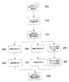
次に、図1の装置を使用してインピーダンス測定値を分析するプロセスの例について、図2を参照しながら説明する。
ステップ200では、被験者の脚の少なくとも一体節のインピーダンスを示す少なくとも1つの第1のインピーダンス値を求める。この処理を実現するには、信号発生器117A、117Bに指示して少なくとも1つの第1の信号を被験者Sへ第1の電極113A、113Bを介して印加させる。この結果、被験者Sに発生する電圧信号が第2の電極115A、115Bを介してセンサ118A、118Bによって測定される。被験者を流れる電流及び被験者で発生した電圧の指標値が処理システム102に提供され、インピーダンス又はインピーダンスパラメータが求められる。
An example process for analyzing impedance measurements using the apparatus of FIG. 1 will now be described with reference to FIG.
In
ステップ210では、第1のインピーダンスを使用して指標が求められる。この指標は、通常、被験者の細胞外液レベルを示す。したがって、一例では、インピーダンス測定は、100kHz未満の単一の低い周波数、例えば5kHzにて実行され、指標は、直接、測定値に基づいたものとなる。或いは、複数の測定を複数の周波数で実行することができ、その場合、指標は、ゼロの印加周波数R0でのインピーダンス等、測定から導出された適切なインピーダンスパラメータ値に基づくものとなる。詳細は以下に説明する。
In
オプションとして、ステップ220では、静脈不全の評価、又は浮腫やリンパ浮腫等の他の病状の評価において指標を使用できる。この点に関して、脚体節の高い細胞外液レベルは脚に浮腫があることを示し、更にこのことは静脈不全が発生している可能性があることを示すものである。一例では、指標を浮腫の基準といったような基準と比較して、浮腫の有無又は重症度を求められるようにすることができる。詳細は以下に説明する。
Optionally, in
浮腫の存在を判定しただけでは、静脈不全又はリンパ浮腫の有無又は重症度について決定的とは言えないので、追加のステップが必要に応じて実行される。
一例では、手順230で、被験者は静脈不全の治療を受けることができる。治療は、アブレーションを実施するなど、複数の方法のうちのいずれか1つで実施可能である。これに続き、ステップ240では、前述したインピーダンス測定を繰り返して、治療後の指標を求めるようにすることができる。治療前に求められた治療前指標と治療後指標との差に基づいて、細胞外液レベルが減少しているかどうかを判定できる。外液レベルに減少がみられれば、治療が少なくとも部分的に成功したことになり、これによりステップ250で静脈不全の存在を確認することができるようになる。
Since simply determining the presence of edema is not critical for the presence or severity of venous insufficiency or lymphedema, additional steps are performed as needed.
In one example, at
この例では、両方の測定とも、通常は、被験者が起立した状態又はこれに相当する姿勢(寄り掛った状態又は脚を実質的に垂直に垂らして座っている状態)で実施される。それにより静脈不全に起因する血液滞留が細胞外液レベルに及ぼす影響が大きくなる。以降の説明では、「起立」という用語は、被験者の脚における血液滞留を最大にする又は増大するいかなる姿勢も包含するものと理解されたい。 In this example, both measurements are typically performed in a state where the subject is standing or equivalent posture (sitting or sitting with his legs hanging substantially vertically). Thereby, the influence of blood retention due to venous insufficiency on the level of extracellular fluid is increased. In the following description, the term “standing” will be understood to encompass any posture that maximizes or increases blood retention in the subject's leg.
別の例では、ステップ260で、第1の指標を求めるのに使用された被験者の姿勢が変更され、異なる姿勢をとった場合の指標の変化が手順270で求められる。
したがって、被験者を第1の姿勢にした状態で第1の指標を求めることにより、基本的な測定値を設定できるようになる。一例では、この処理は、例えば被験者を仰向けにする、必要ならば脚を心臓の位置より最大で20cm高くするなど、被験者を、血液滞留の低減又は最小化が意図された姿勢にして実行される。以降の説明では、「仰向け」という用語は、被験者の脚における血液滞留を最小にするいかなる姿勢も包含するものと理解されたい。
In another example, at
Therefore, a basic measurement value can be set by obtaining the first index in a state where the subject is in the first posture. In one example, this process is performed with the subject in a posture intended to reduce or minimize blood retention, for example, with the subject lying on its back, and if necessary, with the legs up to 20 cm above the heart position. . In the following description, the term “suppose” should be understood to encompass any posture that minimizes blood retention in the subject's leg.
次に、被験者が、起立した状態、寄り掛った状態、又は脚を実質的に垂直に垂らして座った状態で、第2の指標を求めることができる。指標値の変化は脚における細胞外液レベルの変化を示すものであり、これを静脈不全の分析で使用できる。 Next, the second index can be obtained while the subject is standing, leaning, or sitting with his legs hanging substantially vertically. Changes in index values indicate changes in extracellular fluid levels in the leg, which can be used in the analysis of venous insufficiency.
或いは、被験者を起立させたままにして、血液を滞留させることもできる。この後、被験者は仰向けの姿勢に戻され、指標値の監視が可能になる。指標値が、基本的な値に復帰、又は閾値の範囲内に復帰するのにかかる時間を、静脈不全の分析で使用することができる。 Alternatively, the blood can be retained while the subject is standing. Thereafter, the subject is returned to the supine posture, and the index value can be monitored. The time it takes for the index value to return to a basic value or return to within a threshold can be used in the analysis of venous failure.
別の例では、ステップ280で第2のインピーダンス測定が実行され、ステップ290でインデックスを求めることができるようになる。インデックスは、通常、脚又は脚体節の細胞内液レベルと細胞外液レベルとの比を示すものであり、リンパ浮腫の存在を分析するのに使用できる。浮腫とリンパ浮腫とを区別できることは、静脈不全を分析する上で助けになる。
In another example, a second impedance measurement is performed at
前述した例では、測定が被験者の脚で実施される。測定を被験者の脚で実施すると、血液の滞留の影響が最大になり、それによって静脈不全の識別で使用可能な指標を求めるための測定手順の有効性が最大限に高められるからである。但し、この技法をリンパ浮腫等の他の病状を識別するのに使用する場合は、腕等の他の体節にプロセスを適用することができる。詳細は以下に説明する。 In the example described above, the measurement is performed on the subject's leg. This is because, when the measurement is performed on the subject's leg, the effect of blood retention is maximized, thereby maximizing the effectiveness of the measurement procedure to determine an index that can be used to identify venous insufficiency. However, if this technique is used to identify other medical conditions such as lymphedema, the process can be applied to other body segments such as arms. Details will be described below.
次に、図3に関連して装置の特定の例を詳細に説明する。
この例において、測定システム300はコンピュータシステム310と独立した測定機器320とを備える。測定機器320はインターフェイス321に接続されることで、コンピュータシステム310との有線又は無線通信が可能になる。処理システム330はまた、必要に応じて、322、323、324、325、326で図示したような各種メモリ等、1つ又は複数のストアにも接続することができる。
Next, a specific example of the apparatus will be described in detail with reference to FIG.
In this example, the
一例では、インターフェイスはブルートゥース(Bluetooth)スタックであるが、適切な任意のインターフェイスの使用が可能である。メモリとしては、ブートアッププロセスで必要とされる情報を格納するためのブートメモリ322と、デバイスのシリアル番号をプログラム可能なプログラマブルシリアル番号メモリ323を含み得る。メモリとしてはまた、オペレーション中に使用するROM(読み出し専用メモリ)324、フラッシュメモリ325、及びEPROM(電気的プログラム可能型ROM)326を含み得る。当技術分野の当事者には明らかなように、これらのメモリは、例えば、ソフトウェア命令を格納するため、及び処理中のデータを格納するために使用することができる。
In one example, the interface is a Bluetooth stack, but any suitable interface can be used. The memory may include a
処理システム330をセンサ118A、118B及び信号発生器117A、117Bに接続するために、複数のアナログ・デジタル・コンバータ(ADC)327A、327B、328A、328Bとデジタル・アナログ・コンバータ(DAC)329A、329Bとが設けられている。詳細は以下に説明する。
A plurality of analog-to-digital converters (ADC) 327A, 327B, 328A, 328B and digital-to-analog converters (DAC) 329A, 329B are connected to connect the
処理システム330の起動制御のために、マイクロプロセッサ、マイクロコントローラ、プログラマブル・ロジック・デバイス等のコントローラを提供することも可能である。但し、通常は、処理システム330によって実行されるソフトウェア命令によって、これらの制御は行われる。
It is also possible to provide a controller such as a microprocessor, a microcontroller, a programmable logic device, etc., for activation control of the
コンピュータシステム310の例を図4に示す。この例で、コンピュータシステム310は、プロセッサ400と、メモリ401と、キーボードやディスプレイ等の入力/出力装置402と、外部インターフェイス403とを備え、これらは図示のようにバス404によって互いに接続されている。外部インターフェイス403を使用して、コンピュータシステムと測定機器320とが有線又は無線接続を介して必要に応じて通信できるようにすることができる。尚、この外部インターフェイスはネットワークインターフェイスカードやブルートゥーススタック等の形態とすることができる。
An example of a
使用状態では、コンピュータシステム310を使用して測定機器320の動作を制御することができるが、この制御は或いは測定機器300に設けられた独立したインターフェイスによって実現することも可能である。更に、コンピュータシステム310を使用して、インピーダンス測定の分析の少なくとも一部を実行できるようにすることも可能である。
In use, the
したがって、コンピュータシステム310は、適切にプログラムされたPC、インターネット端末、ラップトップ、ハンドヘルドPC、スマートフォン、PDA、サーバ等の適切な処理システムで構成することができ、これにより、適切なアプリケーションソフトウェアを実施して必要なタスクを実行することができる。
Accordingly, the
その一方で、通常は処理システム330によって特定の処理タスクが実行され、コンピュータシステム310での処理要件が軽減される。したがって、処理システムは、通常、命令を実行して信号発生器117A、117Bを制御するための制御信号が生成されるようにする共に、瞬時インピーダンス値を求める処理を実行する。
On the other hand, specific processing tasks are typically performed by the
一例では、処理システム330は、フィールド・プログラマブル・ゲート・アレイ(FPGA)のようなカスタムハードウェア等で構成される。但し、磁気論理モジュール等の任意の適切な処理モジュールを使用してもよい。
In one example, the
一例では、処理システム330はプログラマブルハードウェアを備え、そのハードウェアの動作は、埋め込み型ソフトウェア命令の形態の命令で制御される。プログラマブルハードウェアを使用することにより、被験者Sに様々な信号を印加することができると共に、測定機器320によって様々な分析を実行することができる。したがって、例えば、種々の周波数で順次印加される信号の使用の場合に照らして、複数の周波数でのインピーダンスが同時に分析されるように信号を使用する必要がある場合、様々な埋め込み型ソフトウェアが利用される。
In one example, the
使用する埋め込み型ソフトウェア命令は、コンピュータシステム310からダウンロード可能である。或いは、フラッシュメモリ325等のメモリに命令を格納することができる。こうすれば、測定機器320に設けられた入力装置を使用するか、コンピュータシステム310を使用して、必要な命令を選択することができる。結果として、コンピュータシステム310を使用して、処理システム330によって実施される埋め込み型ソフトウェア等の命令を制御することができ、これにより、処理システム330の動作が変更される。
Embedded software instructions for use can be downloaded from the
更に、コンピュータシステム310は、処理システム330によって求められたインピーダンスを分析するよう動作することができ、これにより生体パラメータが求められる。
単一の処理システムを備えた別の配置を使用することができるが、コンピュータシステム310と処理システム330との間で処理を分配することにより、いくつかの利点がもたらされる。
Further, the
Although other arrangements with a single processing system can be used, distributing processing between
第1に、処理システム330を使用すれば、適切な埋め込み型ソフトウェアによってカスタムハードウェア構成をより簡単に適合させることができる。更に、これにより単一の測定機器を使用して、様々な異なるタイプの分析を実行することができる。
First, using the
第2に、カスタム構成の処理システム330を使用することにより、コンピュータシステム310における処理要件が軽減される。これにより、比較的に簡単なハードウェアを使用してコンピュータシステム310を実現することができるが、それでも測定機器はインピーダンスを解釈するのに十分な分析を実行することができる。例えば、これには、「Wessel」プロットの生成、インピーダンス値を使用した心臓機能に関連するパラメータの特定、リンパ浮腫の有無の判定が含まれ得る。
Second, by using a custom-configured
第3に、測定機器320の更新が可能になる。したがって、例えば、分析アルゴリズムが改良された場合、又は特定のインピーダンス測定タイプについて現行のシーケンスが改良された場合は、フラッシュメモリ325又は外部インターフェイス321を介して新しい埋め込み型ソフトウェアをダウンロードすることにより、測定機器を更新することができる。
Third, the
使用状態では、処理システム330がデジタル制御信号を生成すると、この信号はDAC 329によってアナログの電圧駆動信号VDに変換され、信号発生器117に転送される。被験者に印加された駆動信号IDの電流を示すアナログ信号と、第2の電極115A、115Bで測定された被験者電圧VSは、信号発生器117とセンサ118から受信され、ADC 327、328によってデジタル化される。このデジタル信号は、予備分析のために処理システム330に戻すことができる。
In use, when the
この例では、2つのチャネル(参照番号として接尾語A、Bで示す)のそれぞれに、ADC 327、328、及びDAC 329のセットを使用する。これにより、信号発生器117A、117Bのそれぞれを個別に制御することができ、センサ118A、118Bを使用して電極115A、115Bからの信号をそれぞれ検出することができる。したがって、これは2チャネル装置を意味し、各チャネルは参照番号A、Bで示される。
In this example, a set of ADCs 327, 328, and DAC 329 is used for each of the two channels (denoted by suffixes A, B as reference numbers). Thereby, each of the
実際には、好適な実施形態に応じて適切な数のチャネルを使用できる。したがって、例えば、4チャネル配置を使用することが望ましい場合がある。この配置では、4つの駆動電極と4つのセンス電極が提供され、センス電極と駆動電極の各ペアは各手足に結合される。この場合は、ADC 327、328が8つとDAC 329が4つという配置が使用されるので、各チャネルはそれぞれADC 327、328及びDAC 329を備えることを理解されたい。或いは、当技術分野の当業者には明らかなように、ADC 327、328とDAC 329の2チャネル配置を4チャネル電極配置に選択的に接続するための多重システムを含める等、他の配置を使用することもできる。 In practice, an appropriate number of channels can be used depending on the preferred embodiment. Thus, for example, it may be desirable to use a four channel arrangement. In this arrangement, four drive electrodes and four sense electrodes are provided, and each sense and drive electrode pair is coupled to each limb. In this case, it should be understood that each channel comprises ADC 327, 328 and DAC 329, respectively, as an arrangement of 8 ADCs 327, 328 and 4 DACs 329 is used. Alternatively, other arrangements may be used, such as including multiple systems for selectively connecting the ADC 327, 328 and DAC 329 2-channel arrangement to the 4-channel electrode arrangement, as will be apparent to those skilled in the art. You can also
次に、インピーダンス測定を実行するためのプロセスの例を、図5を参照しながら説明する。
ステップ500で、必要に応じて被験者に電極が装着される。脚のインピーダンスが求められるようにするための一般的な配置は、測定対象の半身において、手の指関節の付け根と、足の足指の付け根に駆動電極113A、113Bを装着するというものである。更に、センス電極115Aを、測定する脚のくるぶしの前面に装着し、センス電極115を反対側に位置する脚の任意の場所に装着する。
Next, an example of a process for performing impedance measurement will be described with reference to FIG.
In
この構成では等電位の理論を使用することで、インピーダンス測定について再現可能な結果をもたらす電極位置を可能にしていることを理解されたい。オペレータによる好ましくない電極配置に起因する測定の変動を大幅に減少させているので、この構成は有利である。 It should be understood that this configuration uses equipotential theory to allow electrode positions that produce reproducible results for impedance measurements. This configuration is advantageous because it greatly reduces measurement variations due to undesired electrode placement by the operator.
但し、これに代わり、他の配置も使用可能である。例えば、対象となる脚の任意の場所にセンス電極を装着することができ、これにより脚全体に沿って、又はふくらはぎ体節等の脚の一部分(一般には脚体節と称する)についてインピーダンス測定が実行される。 However, other arrangements can be used instead. For example, a sense electrode can be mounted anywhere on the subject leg, which allows impedance measurements along the entire leg or for a portion of the leg such as the calf segment (generally referred to as the leg segment). Executed.
ステップ510では、コンピュータシステム310を使用してインピーダンス測定のタイプが選択され、処理システムは、適宜、インピーダンス測定プロトコルを決定し、処理システム330を設定できるようになる。これを実現するには、通常は、前述したような処理システム330内のファームウェア又はソフトウェアの命令を設定する。
At
処理システム300は、ステップ520で次の測定周波数fiを選択し、ステップ530で信号発生器117A、117Bに指示して選択周波数で第1の信号を被験者に対して印加させる。ステップ540で信号発生器117A、117B及びセンサ118A、118Bは脚体節に流れる電流及び脚体節に発生する電圧の指標を処理システム330に提供する。
ステップ550で、処理システム330は、全ての周波数が終了したかどうかを判定し、まだ終了していない場合はステップ520に戻り、次の測定周波数を選択する。ステップ560では、1つ又は複数の測定インピーダンス値が、コンピュータシステム310、処理システム330、又はこの2つの組み合わせによって前述の技法を使用して求められる。ステップ570では、1つ又は複数のインピーダンスパラメータ値を必要に応じて取得することができる。
In
これに関連して、図6Aに生体組織の電気的な振る舞いを効果的にモデル化した等価回路の例を示す。この等価回路には、細胞外液の中を流れる電流と細胞内液の中を流れる電流をそれぞれ示す2つの分岐がある。生体インピーダンスの細胞外液成分は細胞外抵抗Reで示され、一方、細胞内液成分は細胞内抵抗Riと細胞膜を表す容量Cで示される。 In this regard, FIG. 6A shows an example of an equivalent circuit that effectively models the electrical behavior of the living tissue. In this equivalent circuit, there are two branches indicating the current flowing in the extracellular fluid and the current flowing in the intracellular fluid, respectively. The extracellular fluid component of the bioimpedance is indicated by the extracellular resistance Re , while the intracellular fluid component is indicated by the intracellular resistance Ri and the capacitance C representing the cell membrane.
交流電流(AC)のインピーダンスの細胞外成分と細胞内成分の相対振幅は周波数に依存する。ゼロ周波数では、キャパシタは完全な絶縁体として働き、全ての電流が細胞外液を流れるので、ゼロ周波数R0での抵抗は細胞外抵抗Reに等しい。無限周波数では、キャパシタは完全な導体として働くので、電流は並列合成抵抗を流れる。無限周波数R∞での抵抗は、次式で与えられる。 The relative amplitude of the extracellular and intracellular components of the alternating current (AC) impedance depends on the frequency. At zero frequency, the capacitor acts as a perfect insulator, since all of the current flows through the extracellular fluid, the resistance at zero frequency R 0 is equal to the extracellular resistance R e. At infinite frequency, the capacitor acts as a perfect conductor so that current flows through the parallel composite resistor. The resistance at infinite frequency R ∞ is given by
R∞=無限印加周波数でのインピーダンス、
R0=ゼロ印加周波数でのインピーダンス(=Re)、及び、
τは容量性回路の時定数である。
R ∞ = impedance at infinite applied frequency,
R 0 = impedance at zero applied frequency (= R e ), and
τ is the time constant of the capacitive circuit.
但し、上記は理想的な状況を示すものであり、細胞膜はキャパシタとして不完全であるということを考慮していない。このことを考慮すると、修正モデルがもたらされ、次式で表わされる。 However, the above shows an ideal situation and does not consider that the cell membrane is incomplete as a capacitor. Taking this into account, a modified model is derived and is expressed as:
αの値は0と1の間にあり、αは理想モデルからの実システムの偏差を示す指標とみなすことができる。
The value of α is between 0 and 1, and α can be regarded as an index indicating the deviation of the real system from the ideal model.
インピーダンスパラメータR0、R∞、又はZcの値は、以下に示す複数の方法のいずれで求めることが可能である。
・選択された各周波数で実行されたインピーダンス測定値に基づいた値を推定する。
・様々な周波数で求められたインピーダンス値に基づいて連立方程式を解く。
・反復数学的技法を使用する。
・図6Bに図示したのと類似した「Wesselプロット」による外挿法を実行する。
・多項式関数を使用する等の関数あてはめ技法を実行する。
The value of the impedance parameter R 0 , R ∞ , or Z c can be obtained by any of the following methods.
Estimate values based on impedance measurements performed at each selected frequency.
-Solve simultaneous equations based on impedance values obtained at various frequencies.
Use iterative mathematical techniques.
Perform an extrapolation with a “Wessel plot” similar to that shown in FIG. 6B.
• Perform function fitting techniques such as using polynomial functions.
例えば、Wesselプロットは、しばしば生体インピーダンス分光法(BIS)装置で使用され、この装置は4kHz〜1000kHzのような周波数範囲に渡って、この範囲内の256以上の様々な周波数を使用して複数の測定を実行する。回帰手法を使用して、理論的な半円形の軌跡に、測定されたデータをあてはめると、R∞及びR0の値を算出することができる。 For example, Wessel plots are often used in bioimpedance spectroscopy (BIS) devices, which span multiple frequency ranges such as 4 kHz to 1000 kHz, using more than 256 different frequencies within this range. Perform the measurement. Using regression techniques, the theoretical semicircular trajectory, Applying the measured data, it is possible to calculate the value of R ∞ and R 0.
回帰分析は計算コストが高く付くため、計算を実行するのに非常に高い処理能力を備えたデバイスを必要とする。その結果、装置によって消費される電力が比較的に高くなり、大きなバッテリが必要であり、装置の重量増とサイズ増につながる。 Regression analysis is computationally expensive and requires a device with very high processing power to perform the calculations. As a result, the power consumed by the device is relatively high, requiring a large battery, leading to increased weight and size of the device.
更なる問題点として、回帰分析を実行するにはデータ点が多数必要であるが、通常、測定は周波数ごとに順次実行されるので、測定プロセスに時間を要する(数秒)ということが挙げられる。これは、計測状態が長い期間続くと、被験者を不快にさせる可能性があるので、望ましくない。更に、測定手順の間に被験者が動く場合があるが、そのような被験者の動きは、例えば被験者と、環境、リード線、及び電極との間の容量性及び/又は誘導性の結合の変化が原因となり、測定されたインピーダンスに悪影響を及ぼす可能性がある。これは、測定値の正確性が失われる原因となり得る。 A further problem is that a large number of data points are required to perform the regression analysis, but usually the measurement is performed sequentially for each frequency, so that the measurement process takes time (several seconds). This is undesirable as the measurement state lasts for a long period of time, which can make the subject uncomfortable. In addition, the subject may move during the measurement procedure, and such subject movement may be caused, for example, by changes in capacitive and / or inductive coupling between the subject and the environment, leads, and electrodes. This can cause adverse effects on the measured impedance. This can cause a loss of measurement accuracy.
円は次式で記述することが可能である。 A circle can be described by the following equation.
![]()
![]()
更に、円形は図4に示すように軌跡上に位置する3つの座標点(x1〜3、y1〜3)によって一意的に定義することが可能である。したがって、次式(4)に示すように、3つの連立方程式を定義することが可能であり、3点が当てはまる円を記述した3つの軌跡のそれぞれについて1つずつ定義される。 Furthermore, the circle can be uniquely defined by three coordinate points (x 1 to 3 , y 1 to 3 ) located on the locus as shown in FIG. Therefore, as shown in the following equation (4), it is possible to define three simultaneous equations, one for each of three loci describing a circle to which three points apply.
したがって、この技法を使用すると、回帰分析を実行する場合と比較して、R0及び(必要ならば)R∞の値をより低い計算コストで導き出すことができる。更に、この場合は必要なデータ点数が少なくて済む。このため、BIS及び回帰分析を使用してR0の値を求めるよりも、迅速に、且つより基本的なプロセッサを使用してR0の値を求めることができる。この結果としてR0の値を求めるのに必要なデバイスの製造コストが削減される。 Therefore, using this technique, values for R 0 and (if necessary) R ∞ can be derived at a lower computational cost compared to performing regression analysis. Further, in this case, the number of necessary data points is small. Thus, rather than seeking the value of R 0 using BIS and regression analysis quickly, the basic processor than and can determine the value of R 0 using. As a result, the manufacturing cost of the device required to obtain the value of R 0 is reduced.
特に、この技法は少なくとも3つの周波数でインピーダンス測定を実行することにより達成される。各周波数で第1及び第2のインピーダンスパラメータを求めるには、信号の指標が使用される。インピーダンスパラメータ値の性質は、好適な実施形態に応じて変わる。したがって、例えば、インピーダンスパラメータ値には、測定信号に関係する振幅情報や位相情報が含まれる。但し、一例では、インピーダンスパラメータ値は、振幅及び位相信号から導出されるような抵抗やリアクタンスを示す。 In particular, this technique is achieved by performing impedance measurements at at least three frequencies. A signal index is used to determine the first and second impedance parameters at each frequency. The nature of the impedance parameter value varies depending on the preferred embodiment. Therefore, for example, the impedance parameter value includes amplitude information and phase information related to the measurement signal. However, in one example, the impedance parameter value indicates resistance or reactance derived from the amplitude and phase signals.
これが完了すると、3つの周波数のそれぞれで求められた第1及び第2のインピーダンスパラメータ値を使用して連立方程式が解かれ、円パラメータを求められるようになる。パラメータ値によって定義された空間内の円の弧の少なくとも一部分に対応する軌跡を、円パラメータを使用して定義する。したがって、一例では、連立方程式は前述した「Wesselプロット」の場合と同様に、リアクタンス/抵抗空間で提供される円形の軌跡を表す。 When this is completed, the simultaneous equations are solved using the first and second impedance parameter values obtained at each of the three frequencies, and the circular parameter can be obtained. A trajectory corresponding to at least a portion of a circle arc in the space defined by the parameter value is defined using the circle parameter. Thus, in one example, the simultaneous equations represent a circular trajectory provided in the reactance / resistance space, similar to the “Wessel plot” described above.
R0やR∞等の理論的なインピーダンスパラメータ値は、円パラメータから求めることができる。
連立方程式を使用した場合の潜在的な問題点は、何らかの理由でインピーダンス測定のいずれかが正確でない場合に、これが原因でR0の計算値に大きな偏差が生じ得るということである。したがって一例ではインピーダンスの測定は4つ以上の周波数で実行され、3つの周波数でのインピーダンス測定の可能な組み合わせの全てについて円パラメータが計算される。Coleモデルへのデータの適合度の尺度として、標準偏差と共に平均が提供され得る。測定のいずれかが正確でない場合、これを考慮に入れるには、平均から最も大きくずれている測定、又は平均からずれている標準偏差の個数が設定個数を超えている測定等、1つ又は複数の異常値測定を除外する。
Theoretical impedance parameter values such as R 0 and R ∞ can be obtained from the circle parameters.
A potential problem when using simultaneous equations is that if for any reason any of the impedance measurements is not accurate, this can cause a large deviation in the calculated value of R 0 . Thus, in one example, impedance measurements are performed at four or more frequencies, and circle parameters are calculated for all possible combinations of impedance measurements at three frequencies. As a measure of the goodness of fit of the data to the Cole model, an average with standard deviation can be provided. To take this into account if any of the measurements are inaccurate, one or more such as the measurement that is the most deviating from the average, or the number of standard deviations that deviate from the average exceeds the set number Excludes outlier measurement of
このプロセスでは、4つ又は5つの測定といったように追加の測定を使用するが、BIS測定プロトコルを使用する場合に通常256種類以上の周波数で実行することに比べれば、回数はまだはるかに少ないので、測定プロセスをより迅速に実行することが可能である。 This process uses additional measurements, such as four or five measurements, but is still much less frequent when using the BIS measurement protocol compared to typically running at more than 256 frequencies. It is possible to carry out the measurement process more quickly.
一例では、使用される周波数は0kHz〜1000kHzの範囲内にあり、具体例では、25kHz、50kHz、100kHz、及び200kHzの周波数での4つの測定が記録される。但し、任意の適切な測定周波数の使用が可能である。 In one example, the frequency used is in the range of 0 kHz to 1000 kHz, and in the example, four measurements are recorded at frequencies of 25 kHz, 50 kHz, 100 kHz, and 200 kHz. However, any suitable measurement frequency can be used.
R0及びR∞のようなインピーダンスパラメータ値を求める更なる別の方法は、単一周波数でインピーダンス測定を実行し、これらをパラメータ値の推定値として使用するものである。この場合、単一の低周波数で実行される測定を使用してR0を推測することができるが、単一の高周波数での測定を使用してR∞を推定することも可能である。 Yet another method for determining impedance parameter values such as R 0 and R ∞ is to perform impedance measurements at a single frequency and use these as estimates of the parameter values. In this case, R 0 can be estimated using measurements performed at a single low frequency, but R ∞ can also be estimated using measurements at a single high frequency.
前述した等価回路は、抵抗率を定数値としてモデル化するが、被験者のインピーダンス応答を正確に反映しない、具体的には、被験者の血流内の赤血球の向きの変化、又は他の緩和効果を正確にモデル化しない。人体の電気導電性を正常にモデル化するには、改良かれたCPEベースのモデルを代替えとして使用してもよい。 The equivalent circuit described above models the resistivity as a constant value, but does not accurately reflect the subject's impedance response, specifically, changes in the orientation of red blood cells in the subject's bloodstream, or other mitigation effects. Does not model correctly. To successfully model the electrical conductivity of the human body, an improved CPE-based model may be used as an alternative.
いかなる場合も、R0、Zc、及びR∞等のパラメータ値を決定する技法として適切であれば、どんな技法でも使用できることを理解されたい。
インピーダンス測定値を分析して静脈不全についての判断を可能にするプロセスの第1の具体例を、図7を参照しながら説明する。
In any case, it should be understood that any technique that is suitable as a technique for determining parameter values such as R 0 , Z c , and R ∞ can be used.
A first example of a process that analyzes impedance measurements to enable determination of venous insufficiency will be described with reference to FIG.
この例では、ステップ700で、前述した方法を使用して少なくとも1つの第1のインピーダンス値が求められる。測定は、通常、仰向け又は起立した姿勢等、被験者を特定の姿勢にさせて実行される。これは、血液滞留の影響を最大又は最小にするために実行され、実施する分析に応じて変わる。
In this example, at
この第1の具体例では、例えば5分〜15分のような設定された期間、被験者を起立させて血液滞留の影響を最大にする。一般に、5分後に血液滞留が著しく増大し、約15分後に血中濃度が比較的に安定した最大値に達する。したがって、被験者を15分間起立させて血液滞留を最大にすることが好ましいが、5分後でも測定を実行するには十分な血液滞留が発生する。このことから、選択する時間の長さは、測定プロセスに利用できる時間や被験者が起立した姿勢を維持できる能力等の要因に応じて変化し得ることを理解されたい。 In this first specific example, for example, the subject is erected for a set period such as 5 to 15 minutes to maximize the influence of blood retention. In general, blood retention increases significantly after 5 minutes, and the blood concentration reaches a relatively stable maximum after about 15 minutes. Therefore, it is preferable to stand the subject for 15 minutes to maximize blood retention, but sufficient blood retention occurs to perform the measurement even after 5 minutes. From this, it should be understood that the length of time selected may vary depending on factors such as the time available for the measurement process and the ability of the subject to maintain a standing posture.
更に、被験者は、例えば5分〜15分のように起立姿勢をとる前に設定された期間、仰向けに横たわることが必要な場合がある。これを実行して、起立姿勢をとる前に血液滞留を最小にしておけば、測定を実行する前に被験者のより正確な基本状態を提供することができる。この場合も同様に、5分後に血液滞留が著しく減少し、約15分後に血液滞留のレベルが、通常、比較的に安定した最小値に達するので、使用する時間の長さは測定に利用できる時間等の要因に依存する。 Furthermore, the subject may need to lie on his back for a set period of time, for example, before taking a standing posture, such as 5-15 minutes. If this is done and the blood retention is minimized before taking a standing posture, a more accurate basic state of the subject can be provided before the measurement is performed. Again, the blood retention is significantly reduced after 5 minutes and the level of blood retention usually reaches a relatively stable minimum after about 15 minutes so that the length of time used is available for measurement. Depends on factors such as time.
ステップ710では、インピーダンスパラメータ値R0が必要に応じて求められる。複数のインピーダンス値を求める場合は、このステップを実行する。そうでない場合は、単一のインピーダンス測定を例えば10kHz未満のように低周波数で実行することができる。これによって十分に近いR0の近似値が提供されるからである。
In
ステップ720では、被験者の細胞外Reの液体レベルを示す指標が求められ、この指標はステップ730でユーザに表示される。
指標値は、インピーダンスパラメータ値R0の値に基づく数値のように、適切な指標の形態を取り得る。指標は、静脈不全又は浮腫の有無又は重症度を示す数値を提供するようにスケーリングすることもできる。指標はまた、数値を、浮腫の基準値のような基準値と比較した結果に基づくことも可能である。
In
The index value can take the form of an appropriate index, such as a numerical value based on the value of the impedance parameter value R 0 . The indicator can also be scaled to provide a numerical value indicating the presence or severity of venous insufficiency or edema. The indicator can also be based on the result of comparing a numerical value with a reference value, such as a reference value for edema.
浮腫の基準値については、任意の適切な基準値の形態とすることが可能である。したがって、一例では、浮腫の基準値は、腕等の被験者の異なる手足について求められた等価なインピーダンスパラメータ値に基づくことができる。これが可能となるのは、被験者が静脈不全を患っていない場合に異なる手足間の細胞外液レベル間に予測可能な関係が存在するからである。したがって、例えば、細胞外液レベルについて一般的な変化を引き起こす、静脈不全以外の病状に悩まされている場合、それは判断可能な形式で体節に影響を及ぼすので、静脈不全を識別することができる。 The reference value for edema can be in the form of any suitable reference value. Thus, in one example, a reference value for edema can be based on equivalent impedance parameter values determined for different limbs of a subject such as an arm. This is possible because there is a predictable relationship between extracellular fluid levels between different limbs when the subject does not suffer from venous insufficiency. Thus, for example, if you are suffering from a condition other than venous insufficiency that causes a general change in extracellular fluid levels, it affects the somites in a deterministic manner and can identify venous insufficiency .
健康な被験者では様々な体節間で組織にわずかなばらつきを生じる。これは比較において許容誤差を設けることにより、考慮に入れることができる。したがって、例えば、普通の健康な被験者の異なる手足間において自然に予測されるばらつき(例えば手足の優位性や被験者に関する前回の分析等に起因する)を考慮に入れることが可能である。許容誤差はまた、被験者の年齢、体重、性別、及び身長等の複数の要因に左右される場合があり、また、それぞれの範囲はこれらの要因に基づいて選択することができる。 In healthy subjects, slight tissue variability occurs between various somites. This can be taken into account by providing a tolerance in the comparison. Thus, for example, it is possible to take into account variability that is naturally predicted between different limbs of a normal healthy subject (eg, due to limb superiority or previous analysis of the subject). The tolerance may also depend on a number of factors such as the subject's age, weight, gender, and height, and each range can be selected based on these factors.
或いは、浮腫の基準値は、サンプル集団等から導出された基準値に基づくことも可能である。浮腫の基準値は被験者パラメータに基づいて選択することができる。したがって、指標値は、同様の被験者パラメータを有する他人のサンプル集団の調査結果から導出された指標値と比較される。 Alternatively, the reference value for edema can be based on a reference value derived from a sample population or the like. The reference value for edema can be selected based on subject parameters. Therefore, the index value is compared with the index value derived from the survey result of another person's sample population having similar subject parameters.
更なる代替えとして、浮腫の基準値は前に被験者について測定された基準値(例えば被験者が静脈浮腫又は浮腫に悩まされる前に求められた)に基づくことも可能である。これにより縦断的解析を実行することができるので、静脈不全の発症や進行を判断することが可能になる。 As a further alternative, the baseline value for edema can be based on a baseline value previously measured for the subject (eg, determined before the subject suffered from venous or edema). As a result, longitudinal analysis can be executed, and it becomes possible to determine the onset and progression of venous insufficiency.
指標は追加として又は別の方法としてグラフィカル均等目盛又は不均目盛に表示することが可能であり、目盛り上のポインタの位置が細胞外液レベルと、浮腫又は静脈不全の有無又は重症度を示す。一例では、均等目盛は、サンプル集団データや他の基準値から導出されるような、閾値を含めて腫又は静脈不全の有無を示す範囲を表すことができる。 The indicator can additionally or alternatively be displayed on a graphical uniform scale or an irregular scale, where the position of the pointer on the scale indicates the extracellular fluid level and the presence or severity of edema or venous insufficiency. In one example, a uniform scale can represent a range that indicates the presence or absence of a tumor or venous failure, including a threshold, as derived from sample population data or other reference values.
ステップ740では、指標を使用して更なる調査が必要かどうかを判断することができる。この点では、浮腫の存在を示す高い細胞外液レベルは、被験者に静脈不全があることを示すわかりやすい兆候であるが、これについては更なる測定及び/又は分析にて確認を要する場合がある。
In
上記した例では、静脈不全が存在するかどうかの迅速な判断が可能である。これについてはBIAを使用して実行することができる。BIAを使用すると、比較的単純な装置と処理を使用できるので、複雑な技法に比べて、静脈不全を判断するのに必要な装置のコストを削減することができる。このような簡略化にも関わらず、プロセスはSPGやAPG等の現行の非侵襲性の技法より信頼性が高い。この点について、液体レベルの変化は、通常、インピーダンス測定を使用し、液体レベルの変化が手足の体積に及ぼす影響が大きくなる前に検出可能であるため、インピーダンス測定プロセスは、SPG又はAPG等の他の技法に比べて感度が高くなる。 In the example described above, it is possible to quickly determine whether venous insufficiency exists. This can be done using BIA. Using BIA allows the use of relatively simple devices and processes, thus reducing the cost of the device needed to determine venous failure compared to complex techniques. Despite this simplification, the process is more reliable than current non-invasive techniques such as SPG and APG. In this regard, the change in liquid level is usually detected using impedance measurements and can be detected before the effect of the change in liquid level on the volume of the limbs is increased, so the impedance measurement process is similar to SPG or APG. Sensitivity is higher than other techniques.
次に、更なる調査を実行するための例について詳細に説明する。
図8の具体例において、ステップ800では、図7に関連して説明したように被験者に起立の姿勢をとらせて血液滞留を最大にした状態で第1の指標値が求められる。これは、第1の指標が前治療の指標としての役割を果たすように、被験者の治療が行われる前に実施される。ステップ810では、アブレーション等を実施することにより、被験者に対して静脈不全の治療が行われる。次いで、ステップ820では、同様の技法を使用して(即ち、被験者に起立の姿勢をとらせて)、治療後の指標としての役割を果たす第2の指標値が求められる。
Next, an example for performing further investigation will be described in detail.
In the specific example of FIG. 8, in
処理システム102は、次に、ステップ830で、第1の指標値と第2の指標値との差を求め、その差はステップ840にて治療基準値等の基準値と比較される。これにより、変化の妥当性を評価することができる。比較の結果が、閾値を超える細胞外液レベルの減少を示している場合は、治療が成功したか、治療が少なくとも影響していることを示すものであり、ステップ850で静脈不全の存在を確定することができる。また、差の大きさを使用して、静脈不全の重症度、及び/又は治療の効果を判断することもできる。
The
この場合も、複数の方法のいずれかで、治療基準を導き出すことができる。例えば、被験者のサンプル集団から収集したデータを基に治療基準を取得することが可能であり、このサンプル集団はデータのプールとして役割を果たし、このデータのプールから、正常な治療を受けた被験者、治療を受けていない被験者、及び/又は健康な被験者について正規化された期待差を求めることができる。次に治療基準は、年齢、性別、身長、体重、人種、介入等の被験者パラメータに基づいて被験者に関連するように求められた基準値を選択することで生成される。 Again, treatment criteria can be derived in any of a number of ways. For example, it is possible to obtain treatment criteria based on data collected from a sample population of subjects, which serves as a pool of data from which subjects who have received normal treatment, Normalized expectation differences can be determined for untreated and / or healthy subjects. The treatment criteria are then generated by selecting a reference value determined to be relevant to the subject based on subject parameters such as age, gender, height, weight, race, intervention and the like.
この場合、図7の手順に従って静脈不全が存在するという予備的な指標が与えられた場合は、被験者に対して治療が行われ、細胞外液レベルの減少がもたらされたという意味において治療が成功した場合は静脈不全の存在が確定される。したがって、これにより静脈不全の評価の信頼性を高めることが可能である。しかし、静脈不全の治療も同時に行い、被験者が、追加の分析を待機する必要なく、可能な限り迅速な治療を受けられるようにすることが有利である。被験者に静脈不全がない場合、治療を行っても悪影響はない。また、これにより初期評価を実施するのに使用したのと同じ装置を使用して分析を確認することができ、従って、評価を実施する関連の医療従事者のために分析を簡略化できることも理解されたい。 In this case, if a preliminary indication that venous insufficiency is present according to the procedure of FIG. 7 is given, the subject has been treated and treatment has been achieved in the sense that a reduction in extracellular fluid levels has resulted. If successful, the presence of venous insufficiency is confirmed. Thus, this can increase the reliability of the assessment of venous failure. However, it is also advantageous to treat venous insufficiency at the same time so that the subject can receive treatment as quickly as possible without having to wait for additional analysis. If the subject does not have venous insufficiency, treatment will have no adverse effects. It is also understood that this allows the analysis to be confirmed using the same equipment used to perform the initial assessment, and thus simplifies the analysis for the relevant healthcare professional performing the assessment. I want to be.
図9の具体例において、ステップ900では、被験者を仰向けにした状態で第1の指標値が求められる。この測定は、通常、5分〜15分といったように被験者をある設定された時間だけ休ませた状態にした後で実行される。これにより、血液滞留の結果が減少し、基本的な測定値を確立することができる。次に、被験者は例えば5分〜15分のように所定の期間、起立させて血液滞留を最大にする。次いで、ステップ910にて前述した技法を使用して第2の指標値が求められる。先の場合と同様に、第1及び第2の指標値は、細胞外液レベルを示すものであり、1つ又は複数の周波数インピーダンス測定又はインピーダンス測定から何らかの方法で導出されたインピーダンスパラメータ値R0に基づくことが可能である。
In the specific example of FIG. 9, in
ステップ920では、処理システム102が第1と第2の指標値の差を求め、この差はステップ930で滞留基準値のような基準値と比較される。
先の場合と同様に、滞留基準値はサンプル集団等から導き出された類似の指標値に基づくことが可能である。或いは、滞留基準値は、例えば静脈不全の発症前に、被験者についてあらかじめ求められている第1及び第2の指標値に基づくことも可能であり、縦断的解析の実行が可能である。
In
As in the previous case, the residence reference value can be based on a similar index value derived from a sample group or the like. Alternatively, the retention reference value can be based on the first and second index values obtained in advance for the subject before the onset of venous insufficiency, for example, and longitudinal analysis can be performed.
一例では、基準値は基本的な測定値からの変化率として求められるので、変化が15%のような所定量より小さい場合は、被験者が静脈不全を有していないことを示す。変化率が15%のような所定量より大きい場合、滞留レベルは異常であり、被験者が静脈不全を有する可能性があることを示し、変化率の大きさは静脈不全の重症度を示す。したがって、変化が20%より大きい場合、通常は、静脈不全を示す。 In one example, the reference value is determined as a rate of change from a basic measurement, so a change less than a predetermined amount, such as 15%, indicates that the subject does not have venous failure. If the rate of change is greater than a predetermined amount, such as 15%, the residence level is abnormal, indicating that the subject may have venous failure, and the magnitude of the rate of change indicates the severity of venous failure. Thus, if the change is greater than 20%, it usually indicates venous failure.
ステップ940では、変化の関連性を評価できるように、比較の結果を表示することができる。この点について、比較を行った結果、細胞外液レベルの増大が滞留基準から求められた量を超えている場合は、被験者に著しい血液滞留が存在していることを示し、このことは静脈不全があることを示すものである。このことから、第1及び第2の指標値の差の大きさは、静脈不全の重症度を示し得ることを理解されたい。
In
この場合、図7の手順に従って静脈不全が存在するという予備的な指標が与えられた場合は、被験者の姿勢を変えて、測定を再度実行する。この点について、図7のプロセスで導出された指標が起立した姿勢で作成された場合、これは第2の指標としての役割を果たし得るものであり、第1の指標を求められるように被験者の姿勢が変えられる。したがって、「第1」及び「第2」という用語は、それぞれの指標を識別するために使用されるものであり、必ずしも測定の順番を暗示又は要求しているものではない。 In this case, when a preliminary index indicating that venous insufficiency exists is given according to the procedure of FIG. 7, the posture of the subject is changed and the measurement is performed again. In this regard, when the index derived in the process of FIG. 7 is created in an upright posture, this can serve as the second index, so that the subject can be asked to obtain the first index. The posture can be changed. Thus, the terms “first” and “second” are used to identify each indicator and do not necessarily imply or require an order of measurement.
但し、これは必須ではないが、一般に第1の指標を最初に測定すると正確な基本値を確立できるようになる。これにより、従来技術の技法で達成するよりも高い信頼性で静脈不全の評価を行うことができ、初期評価を実行するのに使用するのと同じ装置を使用して分析を確認することができる。また、被験者に対して治療を行わなくても評価を確認することができるので、評価のコスト負荷を削減することができる。 However, this is not essential, but generally an accurate basic value can be established by first measuring the first index. This allows for a more reliable assessment of venous failure than can be achieved with prior art techniques, and the analysis can be verified using the same equipment used to perform the initial assessment. . Moreover, since evaluation can be confirmed even if it does not treat a test subject, the cost burden of evaluation can be reduced.
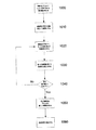
図10の具体例では、ステップ1000で、被験者を仰向けにした状態で第1の指標を求める。前の例と同様に、このステップを実行することにより、基本的な測定値を設定できるようになる。ステップ1010で、被験者は5分〜15分といったような所定の期間、起立した状態を保ち血液滞留を最大にし、それからステップ1020にて、仰向け姿勢に戻り、前述した技法を使用して第2の指標値を求める。
In the specific example of FIG. 10, in
ステップ1030で、処理システム102は第1の指標値と第2の指標値との差を求め、次いでステップ1040で、その差が復帰基準値のような基準値を下回っているかどうか判定する。基準値を下回っていない場合、プロセスはステップ1020に戻り、新しい第2の指標が求められる。
In
基準値は、サンプル集団、被験者に関する前の測定等から導き出すことができる。或いは、基準値は基本的な測定値からの特定の変化率と見なされる。したがって、この例では、基本的な測定値の5〜10%以内に復帰するのにかかる時間を求めることができる。 Reference values can be derived from sample populations, previous measurements on subjects, and the like. Alternatively, the reference value is regarded as a specific rate of change from the basic measurement. Therefore, in this example, it is possible to obtain the time required for returning to within 5 to 10% of the basic measurement value.
第1の指標と第2の指標との差が復帰基準値を下回るまで、ステップ1020〜1040が繰り返される。ステップ1050で、差が滞留基準を下回るのにかかった時間の長さが求められ、ステップ1060でこれがユーザに表示される。
基本的な値(又は基準値)へ復帰するのにかかった時間が基準量(例えば15分)より短い場合は、これは被験者に静脈不全がないことを示している。但し、かかった時間が基準時間を超えた場合、これは被験者に静脈不全があることを示す。 If the time taken to return to a basic value (or reference value) is shorter than a reference amount (eg 15 minutes), this indicates that the subject has no venous insufficiency. However, if the time taken exceeds the reference time, this indicates that the subject has venous insufficiency.
この点に関して、健康な被験者では血液量は比較的迅速に基本的な量に復帰するが、静脈不全を持つ被験者の場合はこれに数分を要する場合がある。したがって、脚の血液滞留が減少するのにかかる時間は静脈不全の有無や重症度を示す。復帰基準を使用すれば、自然な変異を考慮して、適正な期間で測定を実行できるようにすることができる。 In this regard, the blood volume returns to the basic volume relatively quickly in healthy subjects, but this may take several minutes for subjects with venous insufficiency. Thus, the time it takes for leg blood retention to decrease indicates the presence or severity of venous failure. By using the reversion criterion, it is possible to perform the measurement in an appropriate period in consideration of natural variation.
この場合、被験者が基本的な測定値に復帰するのにかかる時間を測定することにより、静脈系が血液滞留を中和する能力に直接相関性を提供する。これにより静脈不全の重症度が直接的に示される。したがって、治療や複雑な装置を必要とすることなく静脈不全の重大度を評価する正確な技法が実現される。 In this case, measuring the time it takes for the subject to return to a basic measurement provides a direct correlation to the ability of the venous system to neutralize blood retention. This directly indicates the severity of venous failure. Thus, an accurate technique is provided that assesses the severity of venous failure without the need for treatment or complex equipment.
次に、図11を参照しながら浮腫とリンパ浮腫を区別するためのプロセスの例について説明する。一例では、このプロセスを使用することにより静脈不全の存在を容易に評価することができる。例えば、被験者の脚で測定が実施され、被験者には浮腫があるがリンパ浮腫はないと判断された場合、この判断結果は被験者に静脈不全があることを示している。或いは、この技法を使用して腕等の他の体節において浮腫とリンパ浮腫を区別することもできる。これにより、被験者の病状に応じて、最適な管理プログラムを容易に特定することができる。 Next, an example of a process for distinguishing between edema and lymphedema will be described with reference to FIG. In one example, this process can be used to easily assess the presence of venous insufficiency. For example, if a measurement is performed on the subject's leg and it is determined that the subject has edema but no lymphedema, the determination results indicate that the subject has venous failure. Alternatively, this technique can be used to distinguish edema and lymphedema in other somites such as arms. Thereby, an optimal management program can be easily specified according to the medical condition of the subject.
したがって、この例では、浮腫とリンパ浮腫を区別できるように体節に一般に適用される技法を説明する。この技法を使用して静脈不全を特定する場合、被験者の脚でプロセスが実行されるが、他の体節にもこのプロセスを適用可能であることを理解されたい。 Therefore, this example describes a technique commonly applied to somites so that edema and lymphedema can be distinguished. When using this technique to identify venous insufficiency, the process is performed on the subject's leg, but it should be understood that the process can be applied to other body segments.
図11の具体的な例では、ステップ1100にて複数の異なる周波数で体節についてインピーダンス値が求められる。この技法を使用して静脈浮腫を特定するのに使用できる指標を求める場合、該当する測定は、通常、被験者を起立姿勢にさせ血液滞留を最大にした状態で実行される。
In the specific example of FIG. 11, in
ステップ1110では、処理システム102が、上記の詳細説明のようにインピーダンスパラメータR0、R∞の値を求める。したがって、この処理の場合は、BIS測定に適用される回帰分析を使用して実行可能である。或いは、プロセスでは、MFBIA及び連立方程式の解を使用して、インピーダンスパラメータ値を求めることが可能である。選択された周波数での個々の測定の組み合わせが使用される他の技法を、適宜、使用することも可能である。したがって、例えば、それぞれ低周波数及び高周波数での単一の測定を、R0及びR∞の推定値として使用することが可能である。
In
ステップ1120では、インピーダンスパラメータ値R0を使用して第1の指標値が求められる。この値は或いは前述した単一の低周波数インピーダンス測定から導出することもできるが、別の例では、後続のステップのために複数の周波数での測定を使用することも可能で、その場合は、追加の単一周波数測定を行う必要性を回避できることを理解されたい。
In
ステップ1130では、体節について、細胞内液と細胞外液との配分を示すインデックスが求められる。一例では、インデックスは細胞外液と細胞内液との比(Ri/Re)を示す。この点について、上記の細胞外液抵抗Reと細胞内液抵抗Riの値を使用すると、インデックスIが次式で与えられる。
In
ステップ1150では、インデックス値が第2の基準値と比較され、その比較の結果により被験者にリンパ浮腫があるかどうかを判断することができる。複数の方法のいずれか1つで、第2の基準値を求めることができる。
In
一例では、インデックスが、別の手足について求められた基準インデックス値と比較される。これは、リンパ浮腫を持たない被験者の場合、異なる体節間であっても通常は細胞内液レベルと細胞外液レベルの度合いが類似しているために、可能となる。通常、異なる体節間では、例えば異なる手足間における生来の違いや手足の優位性に起因して組織内にわずかなばらつきを生じる。これらのばらつきは前述と同様の方法で適切な許容誤差を使用して考慮することができる。追加の方法として、及び/又は、替わりの方法として、サンプル集団や被験者に対して前に行った測定等から導出される基準値のような様々な基準値を使用することができる。 In one example, the index is compared to a reference index value determined for another limb. This is possible for subjects who do not have lymphedema because the levels of intracellular fluid levels and extracellular fluid levels are usually similar, even between different body segments. Usually, there are slight variations in tissues between different body segments due to, for example, innate differences between different limbs and superiority of limbs. These variations can be taken into account using appropriate tolerances in the same manner as described above. As an additional method and / or as an alternative method, various reference values can be used, such as a reference value derived from a sample population, previous measurements, etc. on the subject.
被験者に浮腫及び/又はリンパ浮腫があるかどうかを評価できるように、比較の結果をユーザに表示することができる。
被験者が起立の姿勢をとっている状態で被験者の脚で測定が行われ、被験者にリンパ浮腫ではない浮腫が存在すると予想された場合、これは被験者に静脈不全があることを示している。この場合には、指標値とインデックス値の大きさを基に静脈不全の重症度を評価することができる。或いは、この技法を身体の他の部位で使用して、浮腫とリンパ浮腫を区別することができる。
The results of the comparison can be displayed to the user so that it can be assessed whether the subject has edema and / or lymphedema.
If measurements are made on the subject's legs while the subject is in a standing position and the subject is expected to have edema that is not lymphedema, this indicates that the subject has venous insufficiency. In this case, the severity of venous insufficiency can be evaluated based on the index value and the magnitude of the index value. Alternatively, this technique can be used elsewhere in the body to distinguish between edema and lymphedema.
更なる例では、被験者が仰向け及び起立した姿勢をとっている状態で前述したプロセスを繰り返すことができる。この場合、指標値及びインデックス値の変化が更に、静脈不全の有無又は重症度の評価の助けとなる。 In a further example, the process described above can be repeated with the subject in a supine and upright position. In this case, changes in the index value and the index value further assist in the evaluation of the presence or severity of venous insufficiency.
この例では更に、より複雑なBIS装置が必要であるが、従来技術又は他の技法を使用するよりも、静脈不全の重大度をより正確に示すことが可能である。更に、上記したBIS装置を使用すれば、一部の被験者に適切でない場合がある運動療法を被験者が受ける必要なく、評価を迅速に実行することが可能である。 This example further requires a more complex BIS device, but can more accurately indicate the severity of venous failure than using prior art or other techniques. Furthermore, if the above-described BIS device is used, it is possible to perform the evaluation quickly without requiring the subject to receive exercise therapy that may not be appropriate for some subjects.
上記の例では、「インピーダンス」という用語は一般に測定されたインピーダンス値又はその値から導き出されるインピーダンスパラメータ値を示す。「抵抗」という用語は、リアクタンス測定のアドミタアンス等、インピーダンスに関連する任意の測定値を示す。 In the above example, the term “impedance” generally refers to a measured impedance value or an impedance parameter value derived from that value. The term “resistance” refers to any measurement related to impedance, such as the admittance of reactance measurements.
「処理システム」という用語は、処理を実行することができる任意のコンポーネントを含むことを意図し、1つ又は複数の処理システム及びコンピュータを含めることができる。 The term “processing system” is intended to include any component capable of performing processing, and can include one or more processing systems and computers.
当技術分野の当事者ならば、多くの変形形態及び変更形態が明らかになることを理解できよう。当技術分野の当業者にとって明白となる、かかる変形形態及び変更形態は全て、記載の前に概して示される本発明の思想及び範囲内に包含されると考えられるべきである。 Those skilled in the art will appreciate that many variations and modifications will become apparent. All such variations and modifications that will be apparent to those skilled in the art are to be considered within the spirit and scope of the invention as generally indicated before the description.
前述した種々の例の特徴は、必要に応じて、互いに入れ替えて使用することができる。したがって、例えば、複数の異なる指標を求め、それぞれの閾値と比較することができる。 The features of the various examples described above can be used interchangeably as needed. Therefore, for example, a plurality of different indexes can be obtained and compared with respective threshold values.
更に、上記の例では、ヒトのような被験者に注目したが、上記した測定機器や技法は、いかなる動物にも適用することができ、動物として、これらには限定されないが、霊長類、家畜類、競走馬のような競技用動物などを挙げることができる。 Furthermore, in the above example, attention was paid to a subject such as a human. However, the above-described measuring instruments and techniques can be applied to any animal, and as an animal, but not limited to, primate, livestock And competition animals such as racehorses.
上記した処理は生体指標を求める際に使用でき、生体指標は、ある範囲の病状及び疾患の有無又は重症度を診断するのに使用できる。尚、病状及び疾患として、これに限定されるものではないが、浮腫、リンパ浮腫、身体組成変化等が挙げられる。 The above processing can be used when obtaining a biomarker, and the biomarker can be used to diagnose a range of medical conditions and the presence or severity of a disease. The medical condition and disease include, but are not limited to, edema, lymphedema, and body composition change.
更に、上記の例では、電圧信号を印加して被験者に電流を流す方法に注目したが、これは必須ではなく、電流信号を印加する際にプロセスを使用することもできる。
また、「インピーダンス測定」という用語は、アドミタンスや他の関連する測定を網羅することも理解されたい。
Furthermore, in the above example, attention was paid to a method of applying a voltage signal to flow a current to a subject, but this is not essential, and a process can be used when applying a current signal.
It should also be understood that the term “impedance measurement” covers admittance and other related measurements.
Claims (44)
a)前記被験者の少なくとも1つの脚体節のインピーダンスを示す少なくとも1つのインピーダンス値を求めるステップと、
b)前記少なくとも1つのインピーダンス値を使用して指標を求めるステップであって、前記指標が、前記少なくとも1つの脚体節での細胞外液レベルを示し、静脈不全の評価に使用されるステップと、
を含む方法。 A method for use in an analysis of impedance measurements performed on a subject comprising:
a) determining at least one impedance value indicative of impedance of at least one leg segment of the subject;
b) determining an index using the at least one impedance value, the index indicating an extracellular fluid level in the at least one leg segment and used to assess venous insufficiency; ,
Including methods.
a)前記指標を基準値と比較するステップと、
b)前記比較の結果を示し、静脈不全の有無又は重症度を判定できるようにするステップと、
を含む請求項1に記載の方法。 In the processing system,
a) comparing the indicator to a reference value;
b) showing the result of the comparison, allowing the presence or absence or severity of venous insufficiency to be determined;
The method of claim 1 comprising:
a)前記被験者が第1の姿勢の状態で、第1の指標値を求めるステップと、
b)前記被験者が第2の姿勢の状態で、第2の指標値を求めるステップと、
c)前記第1の液体指標値と前記第2の液体指標値との指標差に基づいて、静脈不全の評価に使用される指標の変化を求めるステップと、
を含む請求項1に記載の方法。 In the processing system,
a) obtaining a first index value when the subject is in a first posture;
b) obtaining a second index value when the subject is in the second posture;
c) determining a change in an index used for evaluating venous insufficiency based on an index difference between the first liquid index value and the second liquid index value;
The method of claim 1 comprising:
a)前記指標の変化を基準値と比較するステップと、
b)前記比較の結果を示し、静脈不全の有無又は重症度を判定できるようにするステップと、
を含む請求項3に記載の方法。 In the processing system,
a) comparing the change in index with a reference value;
b) showing the result of the comparison, allowing the presence or absence or severity of venous insufficiency to be determined;
The method of claim 3 comprising:
a)前記インデックスを基準値と比較するステップと、
b)前記比較の結果を示し、静脈不全の有無又は重症度を判定できるようにするステップと、
を含む請求項5に記載の方法。 In the processing system,
a) comparing the index to a reference value;
b) showing the result of the comparison, allowing the presence or absence or severity of venous insufficiency to be determined;
The method of claim 5 comprising:
b)インデックスが第2の基準値より大きい場合に、静脈不全が存在すると診断するステップを含む請求項6に記載の方法。 7. The method of claim 6, comprising diagnosing venous insufficiency when a) the index is less than the first reference value and b) the index is greater than the second reference value.
a)前記被験者が第1の姿勢の状態で、第1のインデックス値を求めるステップと、
b)前記被験者が第2の姿勢の状態で、第2のインデックス値を求めるステップと、
c)前記第1の液体インデックス値と前記第2の液体インデックス値との差に基づいて、静脈不全の評価に使用されるインデックスの変化を求めるステップと、
を含む請求項5に記載の方法。 In the processing system,
a) obtaining a first index value when the subject is in a first posture;
b) obtaining a second index value when the subject is in the second posture;
c) determining a change in the index used to evaluate venous insufficiency based on the difference between the first fluid index value and the second fluid index value;
The method of claim 5 comprising:
a)前記被験者が第1の姿勢の状態で、第1の指標値を求めるステップと、
b)前記被験者を所定の期間、第2の姿勢にした後で、前記被験者を前記第1の姿勢にして、第2の指標値を求めるステップと、
c)前記第1の液体指標値と前記第2の液体指標値との差を求めるステップであって、前記差が静脈不全の評価に使用されるステップと、
を含む請求項1に記載の方法。 In the processing system,
a) obtaining a first index value when the subject is in a first posture;
b) obtaining the second index value by placing the subject in the first posture after the subject is in the second posture for a predetermined period;
c) determining a difference between the first liquid index value and the second liquid index value, wherein the difference is used to evaluate venous insufficiency;
The method of claim 1 comprising:
a)前記差を監視するステップと、
b)前記差が基準値を下回るまでにかかる所要時間を求めるステップと、
c)前記所要時間を示し、静脈不全の有無又は重症度を判定できるようにするステップと、
を含む請求項9に記載の方法。 In the processing system,
a) monitoring said difference;
b) determining a time required for the difference to fall below a reference value;
c) indicating the time required to allow determination of the presence or severity of venous insufficiency;
The method of claim 9 comprising:
a)前記被験者の治療の前に治療前指標値を求めるステップと、
b)静脈不全についての前記被験者の治療の後に、治療後指標値を求めるステップと、
c)前記治療前指標値と前記治療後指標値との差に基づいて、静脈不全の評価に使用される指標値の変化を求めるステップと、
を含む請求項1に記載の方法。 In the processing system,
a) obtaining a pretreatment index value prior to treatment of the subject;
b) determining a post-treatment index value after treatment of the subject for venous insufficiency;
c) determining a change in the index value used for the evaluation of venous insufficiency based on the difference between the pre-treatment index value and the post-treatment index value;
The method of claim 1 comprising:
a)前記被験者の別の手足について求められた指標又はインデックス、
b)サンプル集団から求められた基準値、及び
c)前記被験者について前に求められた指標又はインデックス
のうちの少なくとも1つである基準値を使用するステップを含む請求項1〜12のいずれか一項に記載の方法。 In the processing system,
a) an index or index determined for another limb of the subject;
13. The method according to any one of the preceding claims, comprising using b) a reference value determined from a sample population, and c) a reference value that is at least one of an index or index previously determined for the subject. The method according to item.
a)指標、
b)インデックス比、
c)インデックス、
d)指標の変化、
e)インデックスの変化、
f)1つ又は複数のインピーダンスパラメータ値、及び
g)比較の結果
のうちの少なくとも1つを表示するステップを含む、請求項1〜13のいずれか一項に記載の方法。 In the processing system,
a) indicators,
b) Index ratio,
c) index,
d) changes in indicators,
e) Index changes,
14. A method according to any one of the preceding claims, comprising the step of displaying at least one of f) one or more impedance parameter values and g) the result of the comparison.
a)100kHz未満、
b)50kHz未満、及び
c)10kHz未満
のうちの少なくとも1つの測定周波数で測定される請求項1〜14のいずれか一項に記載の方法。 The at least one impedance value is
a) less than 100 kHz,
15. A method according to any one of the preceding claims, measured at at least one measurement frequency of b) less than 50 kHz and c) less than 10 kHz.
a)200kHz超、
b)500kHz超、及び
c)1000kHz超
のうちの少なくとも1つの測定周波数で測定されるステップを含む請求項1〜16のいずれか一項に記載の方法。 Measuring at least one second impedance value, wherein the at least one second impedance value comprises:
a) Over 200 kHz,
17. A method according to any one of the preceding claims, comprising the step of measuring at least one measurement frequency of b) greater than 500 kHz and c) greater than 1000 kHz.
a)複数のインピーダンス値を求めるステップと、
b)前記複数のインピーダンス値から少なくとも1つのインピーダンスパラメータ値を求めるステップと、
を含む請求項1〜18のいずれか一項に記載の方法。 In the processing system,
a) obtaining a plurality of impedance values;
b) determining at least one impedance parameter value from the plurality of impedance values;
The method according to claim 1, comprising:
ゼロ周波数での前記抵抗であるR0、
無限周波数での前記抵抗であるR∞、及び
特性周波数での前記抵抗であるZc
のうちの少なくとも1つを含む請求項19に記載の方法。 The impedance parameter value is
R 0 being the resistance at zero frequency,
R ∞ , the resistance at infinite frequency, and Z c, the resistance at characteristic frequency
20. The method of claim 19, comprising at least one of:
a)測定されたインピーダンス値からインピーダンスパラメータR0及びR∞の値を求めるステップと、
b)前記インデックス(I)を次式
を含む請求項20に記載の方法。 In the processing system,
a) obtaining values of impedance parameters R 0 and R ∞ from the measured impedance values;
b) The index (I) is expressed as
21. The method of claim 20, comprising:
前記パラメータ値を次式
式中、
Zが角周波数ωでの測定インピーダンスであり、
τが時定数であり、
αの値が0〜1の範囲にある、
請求項20又は21に記載の方法。 In the processing system,
The parameter value is expressed as
Where
Z is the measured impedance at the angular frequency ω,
τ is the time constant,
the value of α is in the range of 0 to 1,
The method according to claim 20 or 21.
a)第1の電極セットを使用して1つ又は複数の電気信号を前記被験者に印加させるステップと、
b)前記印加された1つ又は複数の信号に応答して、前記被験者に印加された第2の電極セットに発生した電気信号を測定するステップと、
c)前記印加された信号と前記測定された信号とから、少なくとも1つの測定インピーダンス値を求めるステップと、
を含む請求項18に記載の方法。 In a computer system,
a) applying one or more electrical signals to the subject using a first electrode set;
b) measuring an electrical signal generated at a second set of electrodes applied to the subject in response to the applied signal or signals;
c) determining at least one measured impedance value from the applied signal and the measured signal;
The method of claim 18 comprising:
a)前記被験者の少なくとも脚体節のインピーダンスを示す少なくとも1つのインピーダンス値を求め、
b)前記少なくとも脚体節での細胞外液レベルを示し静脈不全の評価に使用される指標を、前記少なくとも1つのインピーダンス値を使用して求める、
ための処理システムを有する装置。 A device for use in analyzing impedance measurements performed on a subject,
a) determining at least one impedance value indicative of impedance of at least the leg segment of the subject;
b) determining an indicator of extracellular fluid level in the at least leg segment and used to assess venous insufficiency using the at least one impedance value;
Apparatus having a processing system for.
b)前記印加された1つ又は複数の信号に応答して、前記被験者に印加された第2の電極セットに発生した電気信号を測定し、且つ
c)前記印加された信号と前記測定された信号とから、少なくとも1つの測定インピーダンス値を求める、
ための処理システムを有する請求項25に記載の装置。 a) causing the subject to apply one or more electrical signals using the first electrode set;
b) in response to the applied signal or signals, measuring an electrical signal generated at a second electrode set applied to the subject; and c) measuring the applied signal and the measured Obtaining at least one measured impedance value from the signal;
26. The apparatus of claim 25, comprising a processing system for:
b)電気信号を検知するためのセンサと、
を有する請求項26に記載の装置。 a) a signal generator for generating an electrical signal;
b) a sensor for detecting an electrical signal;
27. The apparatus of claim 26, comprising:
a)被験者の少なくとも1つの脚体節のインピーダンスを示す少なくとも1つのインピーダンス値を求めるステップと、
b)前記少なくとも1つのインピーダンス値を使用して指標を求めるステップであって、前記指標が、前記少なくとも脚体節での細胞外液レベルを示し、静脈不全の評価に使用されるステップと、
を含む方法。 A method used to assess the presence or severity of venous insufficiency, in a processing system,
a) determining at least one impedance value indicative of the impedance of at least one leg segment of the subject;
b) determining an index using the at least one impedance value, the index indicating an extracellular fluid level in the at least leg segment and used to assess venous insufficiency;
Including methods.
a)前記被験者の少なくとも1つの体節のインピーダンスを示す少なくとも1つのインピーダンス値を求めるステップと、
b)前記少なくとも1つの体節での細胞外液レベルを示す指標を、少なくとも1つのインピーダンス値を使用して求めるステップと、
c)前記少なくとも1つの体節での細胞外液レベルと細胞内液レベルとの比を示すインデックスを、少なくとも1つのインピーダンス値を使用して求めるステップと、
d)前記指標を第1の基準値と比較するステップと、
e)前記インデックスを第2の基準値と比較するステップと、
f)前記比較の結果を示すステップと、
を含む方法。 A method for use in an analysis of impedance measurements performed on a subject comprising:
a) determining at least one impedance value indicative of impedance of at least one body segment of the subject;
b) determining an indicator of extracellular fluid level in the at least one somite using at least one impedance value;
c) determining an index indicating a ratio of extracellular fluid level to intracellular fluid level in the at least one body segment using at least one impedance value;
d) comparing the indicator to a first reference value;
e) comparing the index with a second reference value;
f) showing the result of the comparison;
Including methods.
a)100kHz未満、
b)50kHz未満、及び
c)10kHz未満
のうちの少なくとも1つの測定周波数で測定される請求項24又は25に記載の方法。 The at least one impedance measurement is
a) less than 100 kHz,
26. A method according to claim 24 or 25, measured at at least one measurement frequency of b) less than 50 kHz and c) less than 10 kHz.
a)200kHz超、
b)500kHz超、及び
c)1000kHz超
のうちの少なくとも1つの測定周波数で測定されるステップを含む請求項29〜32のいずれか一項に記載の方法。 Measuring at least one second impedance value, wherein the at least one second impedance value comprises:
a) Over 200 kHz,
33. The method according to any one of claims 29 to 32, comprising measuring at a measurement frequency of at least one of b) greater than 500 kHz and c) greater than 1000 kHz.
a)少なくとも2つのインピーダンス値を求めるステップと、
b)前記少なくとも2つのインピーダンス値から少なくとも1つのインピーダンスパラメータ値を求めるステップと、
を含む請求項29〜34のいずれか一項に記載の方法。 In the processing system,
a) determining at least two impedance values;
b) determining at least one impedance parameter value from the at least two impedance values;
35. The method according to any one of claims 29 to 34, comprising:
a)3つの周波数のそれぞれにて、前記被験者の少なくとも1つの体節の前記インピーダンスに関連して第1及び第2のインピーダンスパラメータの第1及び第2のパラメータ値を求めるステップと、
b)前記第1及び第2のインピーダンスパラメータに関して定義された円を表す連立方程式を解いて円パラメータ値を求めるステップであって、前記連立方程式を前記3つの周波数のそれぞれで前記第1及び第2のパラメータ値を使用して解くステップと、
c)前記円パラメータ値を使用してそれぞれの周波数で第3のインピーダンスパラメータ値を求めるステップと、
d)前記第3のインピーダンスパラメータ値を使用して、前記被験者の前記体節内の相対的な液体レベルを示す指標を求めるステップと、
を含む請求項35に記載の方法。 In the processing system,
a) determining first and second parameter values of first and second impedance parameters in relation to the impedance of at least one body segment of the subject at each of three frequencies;
b) solving a simultaneous equation representing a circle defined with respect to the first and second impedance parameters to obtain a circle parameter value, wherein the simultaneous equation is calculated at the first and second frequencies at the three frequencies, respectively. Solving using the parameter values of
c) determining a third impedance parameter value at each frequency using the circle parameter value;
d) using the third impedance parameter value to determine an index indicative of a relative fluid level in the body segment of the subject;
36. The method of claim 35, comprising:
ゼロ周波数での前記抵抗であるR0、
無限周波数での前記抵抗であるR∞、及び
特性周波数での前記抵抗であるZc
のうちの少なくとも1つを含む請求項35〜37のいずれか一項に記載の方法。 The impedance parameter value is
R 0 being the resistance at zero frequency,
R ∞ , the resistance at infinite frequency, and Z c, the resistance at characteristic frequency
38. A method according to any one of claims 35 to 37, comprising at least one of the following.
a)測定されたインピーダンス値からインピーダンスパラメータR0及びR∞の値を求めるステップと、
b)前記インデックス(I)を次式
を含む請求項38に記載の方法。 In the processing system,
a) obtaining values of impedance parameters R 0 and R ∞ from the measured impedance values;
b) The index (I) is expressed as
40. The method of claim 38, comprising:
前記パラメータ値を次式
式中、
Zが角周波数ωでの測定インピーダンスであり、
τが時定数であり、
αの値が0〜1の範囲にある請求項38又は39に記載の方法。 In the processing system,
The parameter value is expressed as
Where
Z is the measured impedance at the angular frequency ω,
τ is the time constant,
40. A method according to claim 38 or 39, wherein the value of [alpha] is in the range of 0-1.
a)前記被験者の少なくとも1つの体節のインピーダンスを示す少なくとも1つのインピーダンス値を求め、
b)前記少なくとも1つの体節での細胞外液レベルを示す指標を、少なくとも1つのインピーダンス値を使用して求め、
c)前記少なくとも1つの体節での細胞外液レベルと細胞内液レベルとの比を示すインデックスを、少なくとも1つのインピーダンス値を使用して求め、
d)前記指標を第1の基準値と比較し、
e)前記インデックスを第2の基準値と比較し、且つ
f)前記比較の結果を示す、
ための処理システムを有する、装置。 A device for use in analyzing impedance measurements performed on a subject,
a) determining at least one impedance value indicative of impedance of at least one body segment of the subject;
b) determining an indicator of extracellular fluid level in said at least one segment using at least one impedance value;
c) determining an index indicating a ratio of extracellular fluid level to intracellular fluid level in the at least one somatic segment using at least one impedance value;
d) comparing said index with a first reference value;
e) comparing the index with a second reference value; and f) indicating the result of the comparison.
An apparatus having a processing system for.
a)第1の電極セットを使用して1つ又は複数の電気信号を前記被験者に印加させ、
b)前記印加された1つ又は複数の信号に応答して、前記被験者に印加された第2の電極セットに発生した電気信号を測定し、且つ
c)前記印加された信号と前記測定された信号とから、少なくとも1つの測定インピーダンス値を求めるためにある請求項41に記載の装置。 The processing system is
a) causing the subject to apply one or more electrical signals using the first electrode set;
b) in response to the applied signal or signals, measuring an electrical signal generated at a second electrode set applied to the subject; and c) measuring the applied signal and the measured 42. The apparatus of claim 41, for determining at least one measured impedance value from the signal.
b)電気信号を検知するためのセンサと、
を有する請求項33又は34に記載の装置。 a) a signal generator for generating an electrical signal;
b) a sensor for detecting an electrical signal;
35. A device according to claim 33 or 34.
a)前記被験者の少なくとも1つの体節のインピーダンスを示す少なくとも1つのインピーダンス値を求めるステップと、
b)前記少なくとも1つの体節での細胞外液レベルを示す指標を、少なくとも1つのインピーダンス値を使用して求めるステップと、
c)前記少なくとも1つの体節での細胞外液レベルと細胞内液レベルとの比を示すインデックスを、少なくとも1つのインピーダンス値を使用して求めるステップと、
d)前記指標を第1の基準値と比較するステップと、
e)前記インデックスを第2の基準値と比較するステップと、
f)浮腫とリンパ浮腫を区別するのに使用される前記比較の結果を示すステップと、
を含む方法。 A method for use in distinguishing between the presence of edema and lymphedema in a subject, comprising:
a) determining at least one impedance value indicative of impedance of at least one body segment of the subject;
b) determining an indicator of extracellular fluid level in the at least one somite using at least one impedance value;
c) determining an index indicating a ratio of extracellular fluid level to intracellular fluid level in the at least one body segment using at least one impedance value;
d) comparing the indicator to a first reference value;
e) comparing the index with a second reference value;
f) showing the result of the comparison used to distinguish between edema and lymphedema;
Including methods.
Applications Claiming Priority (2)
| Application Number | Priority Date | Filing Date | Title |
|---|---|---|---|
| US2927208P | 2008-02-15 | 2008-02-15 | |
| PCT/AU2009/000163 WO2009100491A1 (en) | 2008-02-15 | 2009-02-12 | Analysing impedance measurements |
Related Child Applications (1)
| Application Number | Title | Priority Date | Filing Date |
|---|---|---|---|
| JP2014215681A Division JP6089016B2 (en) | 2008-02-15 | 2014-10-22 | Method of operating an apparatus for analyzing impedance measurements |
Publications (2)
| Publication Number | Publication Date |
|---|---|
| JP2011511679A true JP2011511679A (en) | 2011-04-14 |
| JP2011511679A5 JP2011511679A5 (en) | 2012-03-29 |
Family
ID=40956556
Family Applications (2)
| Application Number | Title | Priority Date | Filing Date |
|---|---|---|---|
| JP2010546182A Pending JP2011511679A (en) | 2008-02-15 | 2009-02-12 | Impedance measurement analysis |
| JP2014215681A Expired - Fee Related JP6089016B2 (en) | 2008-02-15 | 2014-10-22 | Method of operating an apparatus for analyzing impedance measurements |
Family Applications After (1)
| Application Number | Title | Priority Date | Filing Date |
|---|---|---|---|
| JP2014215681A Expired - Fee Related JP6089016B2 (en) | 2008-02-15 | 2014-10-22 | Method of operating an apparatus for analyzing impedance measurements |
Country Status (5)
| Country | Link |
|---|---|
| EP (1) | EP2242423B1 (en) |
| JP (2) | JP2011511679A (en) |
| AU (1) | AU2009214826B2 (en) |
| CA (1) | CA2714367A1 (en) |
| WO (1) | WO2009100491A1 (en) |
Cited By (2)
| Publication number | Priority date | Publication date | Assignee | Title |
|---|---|---|---|---|
| JP2013506485A (en) * | 2009-10-02 | 2013-02-28 | コーニンクレッカ フィリップス エレクトロニクス エヌ ヴィ | Sending a signal through a medium |
| JP2016055191A (en) * | 2009-12-21 | 2016-04-21 | インぺディメッド リミテッドImpedimed Limited | Analysis of impedance measurement value |
Families Citing this family (15)
| Publication number | Priority date | Publication date | Assignee | Title |
|---|---|---|---|---|
| AUPQ113799A0 (en) | 1999-06-22 | 1999-07-15 | University Of Queensland, The | A method and device for measuring lymphoedema |
| CA2578106C (en) | 2004-06-18 | 2015-09-01 | The University Of Queensland | Oedema detection |
| WO2006056074A1 (en) | 2004-11-26 | 2006-06-01 | Z-Tech (Canada) Inc. | Weighted gradient method and system for diagnosing disease |
| CA2608962C (en) | 2005-07-01 | 2016-12-06 | Scott Chetham | Monitoring system |
| EP1898784B1 (en) | 2005-07-01 | 2016-05-18 | Impedimed Limited | Method and apparatus for performing impedance measurements |
| CA2625631C (en) | 2005-10-11 | 2016-11-29 | Impedance Cardiology Systems, Inc. | Hydration status monitoring |
| JP5372768B2 (en) | 2006-11-30 | 2013-12-18 | インぺディメッド リミテッド | measuring device |
| US10307074B2 (en) | 2007-04-20 | 2019-06-04 | Impedimed Limited | Monitoring system and probe |
| CA2704061C (en) | 2007-11-05 | 2017-06-20 | Impedimed Limited | Impedance determination |
| AU2008207672B2 (en) | 2008-02-15 | 2013-10-31 | Impedimed Limited | Impedance Analysis |
| EP2348986B1 (en) * | 2008-11-10 | 2015-07-08 | Impedimed Limited | Fluid indicator |
| WO2010060152A1 (en) | 2008-11-28 | 2010-06-03 | Impedimed Limited | Impedance measurement process |
| US9615767B2 (en) | 2009-10-26 | 2017-04-11 | Impedimed Limited | Fluid level indicator determination |
| EP2501283B1 (en) | 2009-11-18 | 2016-09-21 | Impedimed Limited | Signal distribution for patient-electrode measurements |
| CN108055823A (en) * | 2015-07-16 | 2018-05-18 | 伊派迪迈德公司 | Fluid levels determine |
Citations (1)
| Publication number | Priority date | Publication date | Assignee | Title |
|---|---|---|---|---|
| WO2007041783A1 (en) * | 2005-10-11 | 2007-04-19 | Impedance Cardiology Systems, Inc. | Hydration status monitoring |
Family Cites Families (11)
| Publication number | Priority date | Publication date | Assignee | Title |
|---|---|---|---|---|
| US3996924A (en) * | 1974-06-19 | 1976-12-14 | Wheeler H Brownell | Occlusive impedance phlebograph and method therefor |
| JP3699640B2 (en) * | 2000-08-01 | 2005-09-28 | 株式会社タニタ | Body water content state determination device by multi-frequency bioimpedance measurement |
| JP3943955B2 (en) * | 2002-02-25 | 2007-07-11 | 株式会社タニタ | Deep vein thrombosis determination device |
| AT413189B (en) * | 2002-10-07 | 2005-12-15 | Cnsystems Medizintechnik Gmbh | MEDICAL ELECTRODE ELEMENT |
| US7783345B2 (en) * | 2002-10-07 | 2010-08-24 | Cnsystems Medizintechnik Gmbh | Impedance-based measuring method for hemodynamic parameters |
| CA2578106C (en) * | 2004-06-18 | 2015-09-01 | The University Of Queensland | Oedema detection |
| US20060111652A1 (en) | 2004-11-22 | 2006-05-25 | Mcleod Kenneth J | Method for enhancing blood and lymph flow in the extremities |
| EP1903938A4 (en) * | 2005-07-01 | 2010-01-20 | Impedance Cardiology Systems I | Pulmonary monitoring system |
| EP1898784B1 (en) * | 2005-07-01 | 2016-05-18 | Impedimed Limited | Method and apparatus for performing impedance measurements |
| CA2608962C (en) * | 2005-07-01 | 2016-12-06 | Scott Chetham | Monitoring system |
| AT502921B1 (en) * | 2005-10-21 | 2012-01-15 | Falko Dr Skrabal | DEVICE FOR MEASURING HEART AND VESSEL FUNCTION (FUNCTION) AND BODY SPACES (SPACES) BY MEANS OF IMPEDANCE MEASUREMENT |
-
2009
- 2009-02-12 CA CA2714367A patent/CA2714367A1/en not_active Abandoned
- 2009-02-12 JP JP2010546182A patent/JP2011511679A/en active Pending
- 2009-02-12 AU AU2009214826A patent/AU2009214826B2/en not_active Ceased
- 2009-02-12 WO PCT/AU2009/000163 patent/WO2009100491A1/en active Application Filing
- 2009-02-12 EP EP09710912.8A patent/EP2242423B1/en not_active Not-in-force
-
2014
- 2014-10-22 JP JP2014215681A patent/JP6089016B2/en not_active Expired - Fee Related
Patent Citations (2)
| Publication number | Priority date | Publication date | Assignee | Title |
|---|---|---|---|---|
| WO2007041783A1 (en) * | 2005-10-11 | 2007-04-19 | Impedance Cardiology Systems, Inc. | Hydration status monitoring |
| JP2009511131A (en) * | 2005-10-11 | 2009-03-19 | インピーダンス・カーディオロジー・システムズ・インコーポレイテッド | Hydration status monitoring |
Cited By (2)
| Publication number | Priority date | Publication date | Assignee | Title |
|---|---|---|---|---|
| JP2013506485A (en) * | 2009-10-02 | 2013-02-28 | コーニンクレッカ フィリップス エレクトロニクス エヌ ヴィ | Sending a signal through a medium |
| JP2016055191A (en) * | 2009-12-21 | 2016-04-21 | インぺディメッド リミテッドImpedimed Limited | Analysis of impedance measurement value |
Also Published As
| Publication number | Publication date |
|---|---|
| JP2015037600A (en) | 2015-02-26 |
| CA2714367A1 (en) | 2009-08-20 |
| EP2242423B1 (en) | 2016-04-13 |
| EP2242423A1 (en) | 2010-10-27 |
| JP6089016B2 (en) | 2017-03-01 |
| EP2242423A4 (en) | 2013-05-22 |
| AU2009214826A1 (en) | 2009-08-20 |
| WO2009100491A1 (en) | 2009-08-20 |
| AU2009214826B2 (en) | 2014-12-18 |
Similar Documents
| Publication | Publication Date | Title |
|---|---|---|
| JP6089016B2 (en) | Method of operating an apparatus for analyzing impedance measurements | |
| US20110060239A1 (en) | Analysing impedance measurements | |
| US20170238837A1 (en) | Analysing impedance measurements | |
| US9392947B2 (en) | Blood flow assessment of venous insufficiency | |
| JP5161772B2 (en) | Impedance parameter value | |
| US9504406B2 (en) | Measurement apparatus | |
| EP2211714B1 (en) | Impedance determination | |
| AU2008241356B2 (en) | Monitoring system and probe | |
| AU2009311270B2 (en) | Fluid indicator | |
| JP2010533040A (en) | Heart monitor system | |
| EP1909642A1 (en) | Index determination | |
| JP2019509153A (en) | Heart failure indicator | |
| AU2011274290B2 (en) | Tissue indicator determination | |
| AU2006301927B2 (en) | Hydration status monitoring | |
| JP2001224566A (en) | Electrode apparatus used for electric characteristic measuring instrument |
Legal Events
| Date | Code | Title | Description |
|---|---|---|---|
| A521 | Request for written amendment filed |
Free format text: JAPANESE INTERMEDIATE CODE: A523 Effective date: 20120210 |
|
| A621 | Written request for application examination |
Free format text: JAPANESE INTERMEDIATE CODE: A621 Effective date: 20120210 |
|
| RD04 | Notification of resignation of power of attorney |
Free format text: JAPANESE INTERMEDIATE CODE: A7424 Effective date: 20120224 |
|
| A977 | Report on retrieval |
Free format text: JAPANESE INTERMEDIATE CODE: A971007 Effective date: 20130711 |
|
| A131 | Notification of reasons for refusal |
Free format text: JAPANESE INTERMEDIATE CODE: A131 Effective date: 20130806 |
|
| A02 | Decision of refusal |
Free format text: JAPANESE INTERMEDIATE CODE: A02 Effective date: 20140624 |