JP2011510217A - Scroll compressor and manufacturing method by positioning housing shell thereof - Google Patents
Scroll compressor and manufacturing method by positioning housing shell thereof Download PDFInfo
- Publication number
- JP2011510217A JP2011510217A JP2010543236A JP2010543236A JP2011510217A JP 2011510217 A JP2011510217 A JP 2011510217A JP 2010543236 A JP2010543236 A JP 2010543236A JP 2010543236 A JP2010543236 A JP 2010543236A JP 2011510217 A JP2011510217 A JP 2011510217A
- Authority
- JP
- Japan
- Prior art keywords
- scroll compressor
- shell section
- region
- housing
- compressor body
- Prior art date
- Legal status (The legal status is an assumption and is not a legal conclusion. Google has not performed a legal analysis and makes no representation as to the accuracy of the status listed.)
- Pending
Links
Images


Classifications
-
- F—MECHANICAL ENGINEERING; LIGHTING; HEATING; WEAPONS; BLASTING
- F01—MACHINES OR ENGINES IN GENERAL; ENGINE PLANTS IN GENERAL; STEAM ENGINES
- F01C—ROTARY-PISTON OR OSCILLATING-PISTON MACHINES OR ENGINES
- F01C21/00—Component parts, details or accessories not provided for in groups F01C1/00 - F01C20/00
- F01C21/007—General arrangements of parts; Frames and supporting elements
-
- F—MECHANICAL ENGINEERING; LIGHTING; HEATING; WEAPONS; BLASTING
- F01—MACHINES OR ENGINES IN GENERAL; ENGINE PLANTS IN GENERAL; STEAM ENGINES
- F01C—ROTARY-PISTON OR OSCILLATING-PISTON MACHINES OR ENGINES
- F01C21/00—Component parts, details or accessories not provided for in groups F01C1/00 - F01C20/00
- F01C21/02—Arrangements of bearings
-
- F—MECHANICAL ENGINEERING; LIGHTING; HEATING; WEAPONS; BLASTING
- F04—POSITIVE - DISPLACEMENT MACHINES FOR LIQUIDS; PUMPS FOR LIQUIDS OR ELASTIC FLUIDS
- F04C—ROTARY-PISTON, OR OSCILLATING-PISTON, POSITIVE-DISPLACEMENT MACHINES FOR LIQUIDS; ROTARY-PISTON, OR OSCILLATING-PISTON, POSITIVE-DISPLACEMENT PUMPS
- F04C18/00—Rotary-piston pumps specially adapted for elastic fluids
- F04C18/02—Rotary-piston pumps specially adapted for elastic fluids of arcuate-engagement type, i.e. with circular translatory movement of co-operating members, each member having the same number of teeth or tooth-equivalents
- F04C18/0207—Rotary-piston pumps specially adapted for elastic fluids of arcuate-engagement type, i.e. with circular translatory movement of co-operating members, each member having the same number of teeth or tooth-equivalents both members having co-operating elements in spiral form
-
- F—MECHANICAL ENGINEERING; LIGHTING; HEATING; WEAPONS; BLASTING
- F04—POSITIVE - DISPLACEMENT MACHINES FOR LIQUIDS; PUMPS FOR LIQUIDS OR ELASTIC FLUIDS
- F04C—ROTARY-PISTON, OR OSCILLATING-PISTON, POSITIVE-DISPLACEMENT MACHINES FOR LIQUIDS; ROTARY-PISTON, OR OSCILLATING-PISTON, POSITIVE-DISPLACEMENT PUMPS
- F04C18/00—Rotary-piston pumps specially adapted for elastic fluids
- F04C18/02—Rotary-piston pumps specially adapted for elastic fluids of arcuate-engagement type, i.e. with circular translatory movement of co-operating members, each member having the same number of teeth or tooth-equivalents
- F04C18/04—Rotary-piston pumps specially adapted for elastic fluids of arcuate-engagement type, i.e. with circular translatory movement of co-operating members, each member having the same number of teeth or tooth-equivalents of internal-axis type
-
- F—MECHANICAL ENGINEERING; LIGHTING; HEATING; WEAPONS; BLASTING
- F04—POSITIVE - DISPLACEMENT MACHINES FOR LIQUIDS; PUMPS FOR LIQUIDS OR ELASTIC FLUIDS
- F04C—ROTARY-PISTON, OR OSCILLATING-PISTON, POSITIVE-DISPLACEMENT MACHINES FOR LIQUIDS; ROTARY-PISTON, OR OSCILLATING-PISTON, POSITIVE-DISPLACEMENT PUMPS
- F04C18/00—Rotary-piston pumps specially adapted for elastic fluids
- F04C18/08—Rotary-piston pumps specially adapted for elastic fluids of intermeshing-engagement type, i.e. with engagement of co-operating members similar to that of toothed gearing
- F04C18/082—Details specially related to intermeshing engagement type pumps
- F04C18/086—Carter
-
- F—MECHANICAL ENGINEERING; LIGHTING; HEATING; WEAPONS; BLASTING
- F04—POSITIVE - DISPLACEMENT MACHINES FOR LIQUIDS; PUMPS FOR LIQUIDS OR ELASTIC FLUIDS
- F04C—ROTARY-PISTON, OR OSCILLATING-PISTON, POSITIVE-DISPLACEMENT MACHINES FOR LIQUIDS; ROTARY-PISTON, OR OSCILLATING-PISTON, POSITIVE-DISPLACEMENT PUMPS
- F04C23/00—Combinations of two or more pumps, each being of rotary-piston or oscillating-piston type, specially adapted for elastic fluids; Pumping installations specially adapted for elastic fluids; Multi-stage pumps specially adapted for elastic fluids
- F04C23/008—Hermetic pumps
-
- F—MECHANICAL ENGINEERING; LIGHTING; HEATING; WEAPONS; BLASTING
- F04—POSITIVE - DISPLACEMENT MACHINES FOR LIQUIDS; PUMPS FOR LIQUIDS OR ELASTIC FLUIDS
- F04C—ROTARY-PISTON, OR OSCILLATING-PISTON, POSITIVE-DISPLACEMENT MACHINES FOR LIQUIDS; ROTARY-PISTON, OR OSCILLATING-PISTON, POSITIVE-DISPLACEMENT PUMPS
- F04C27/00—Sealing arrangements in rotary-piston pumps specially adapted for elastic fluids
- F04C27/007—Sealings for working fluid between radially and axially moving parts
-
- F—MECHANICAL ENGINEERING; LIGHTING; HEATING; WEAPONS; BLASTING
- F04—POSITIVE - DISPLACEMENT MACHINES FOR LIQUIDS; PUMPS FOR LIQUIDS OR ELASTIC FLUIDS
- F04C—ROTARY-PISTON, OR OSCILLATING-PISTON, POSITIVE-DISPLACEMENT MACHINES FOR LIQUIDS; ROTARY-PISTON, OR OSCILLATING-PISTON, POSITIVE-DISPLACEMENT PUMPS
- F04C2230/00—Manufacture
- F04C2230/60—Assembly methods
- F04C2230/603—Centering; Aligning
-
- F—MECHANICAL ENGINEERING; LIGHTING; HEATING; WEAPONS; BLASTING
- F04—POSITIVE - DISPLACEMENT MACHINES FOR LIQUIDS; PUMPS FOR LIQUIDS OR ELASTIC FLUIDS
- F04C—ROTARY-PISTON, OR OSCILLATING-PISTON, POSITIVE-DISPLACEMENT MACHINES FOR LIQUIDS; ROTARY-PISTON, OR OSCILLATING-PISTON, POSITIVE-DISPLACEMENT PUMPS
- F04C2230/00—Manufacture
- F04C2230/70—Disassembly methods
-
- F—MECHANICAL ENGINEERING; LIGHTING; HEATING; WEAPONS; BLASTING
- F04—POSITIVE - DISPLACEMENT MACHINES FOR LIQUIDS; PUMPS FOR LIQUIDS OR ELASTIC FLUIDS
- F04C—ROTARY-PISTON, OR OSCILLATING-PISTON, POSITIVE-DISPLACEMENT MACHINES FOR LIQUIDS; ROTARY-PISTON, OR OSCILLATING-PISTON, POSITIVE-DISPLACEMENT PUMPS
- F04C2240/00—Components
- F04C2240/30—Casings or housings
-
- Y—GENERAL TAGGING OF NEW TECHNOLOGICAL DEVELOPMENTS; GENERAL TAGGING OF CROSS-SECTIONAL TECHNOLOGIES SPANNING OVER SEVERAL SECTIONS OF THE IPC; TECHNICAL SUBJECTS COVERED BY FORMER USPC CROSS-REFERENCE ART COLLECTIONS [XRACs] AND DIGESTS
- Y10—TECHNICAL SUBJECTS COVERED BY FORMER USPC
- Y10T—TECHNICAL SUBJECTS COVERED BY FORMER US CLASSIFICATION
- Y10T29/00—Metal working
- Y10T29/49—Method of mechanical manufacture
- Y10T29/49229—Prime mover or fluid pump making
- Y10T29/49236—Fluid pump or compressor making
- Y10T29/4924—Scroll or peristaltic type
Landscapes
- Engineering & Computer Science (AREA)
- Mechanical Engineering (AREA)
- General Engineering & Computer Science (AREA)
- Rotary Pumps (AREA)
- Applications Or Details Of Rotary Compressors (AREA)
Abstract
スクロール圧縮機は、複数のスクロール圧縮機体の1つを基準として位置決めされるハウジングシェルセクションの位置決めのための特徴を含む。この態様によれば、スクロール圧縮機は、シェルセクションを含むハウジングと、複数のスクロール圧縮機体であって、それぞれの基部と、流体を圧縮するためにそれぞれの基部から突出して軸の周りにおいて互いに係合するスクロールリブとを有する、複数のスクロール圧縮機体と、複数のスクロール圧縮機体の間の相対的な運動を可能とするように作動する駆動ユニットとを備える。シェルセクションは、複数のスクロール圧縮機体の1つを基準として位置決めされることにより、ハウジングの残りの部分に対して軸方向において相対的に位置決めされる。
The scroll compressor includes features for positioning a housing shell section that is positioned relative to one of the plurality of scroll compressor bodies. According to this aspect, the scroll compressor is a housing including a shell section and a plurality of scroll compressor bodies, each base projecting from each base to compress fluid and engaging with each other about an axis. A plurality of scroll compressor bodies having mating scroll ribs and a drive unit that operates to allow relative movement between the plurality of scroll compressor bodies; The shell section is positioned relative to the remainder of the housing in the axial direction by being positioned relative to one of the plurality of scroll compressor bodies.
Description
本発明は、一般には、冷媒を圧縮するためのスクロール圧縮機に関し、より詳細には、かかるスクロール圧縮機のハウジングシェルセクションの位置決めに関する。 The present invention relates generally to scroll compressors for compressing refrigerant, and more particularly to positioning a housing shell section of such a scroll compressor.
スクロール圧縮機は圧縮機の一種であり、冷蔵、空調、産業用の冷却および冷凍の各用途ならびに/または圧縮された流体を使用する他の用途において冷媒を圧縮するために用いられる。このような従来のスクロール圧縮機は公知であり、例えば、Hasemannに発行された米国特許第6,398,530号、Kammhoff等に発行された米国特許第6,814,551号、Kammhoff等に発行された米国特許第6,960,070号およびKammhoff等に発行された米国特許第7,112,046号に例示されているが、上記特許はいずれも、本願出願人と密接な関係にあるBitzer事業体に譲渡されている。本発明は、これらのスクロール圧縮機または他のスクロール圧縮機の設計に組み込み可能な改良を開示していることから、米国特許第6,398,530号、7,112,046号、6,814,551号および6,960,070号は、その開示内容の全体を参照することにより本明細書に組み込まれる。 A scroll compressor is a type of compressor and is used to compress refrigerant in refrigeration, air conditioning, industrial cooling and refrigeration applications and / or other applications that use compressed fluids. Such conventional scroll compressors are known, for example, U.S. Pat. No. 6,398,530 issued to Hasmann, U.S. Pat. No. 6,814,551 issued to Kammmoff et al., Issued to Kammmoff et al. U.S. Pat. No. 6,960,070 and U.S. Pat. No. 7,112,046 issued to Kamhoff et al., All of which are bitzers closely related to the present applicant. Has been transferred to the entity. Since the present invention discloses improvements that can be incorporated into these or other scroll compressor designs, US Pat. Nos. 6,398,530, 7,112,046, 6,814. , 551 and 6,960,070 are hereby incorporated by reference in their entirety.
これらの特許で例示するように、従来、スクロール圧縮機は、該スクロール圧縮機を収容する外側ハウジングを備える。スクロール圧縮機は、第1および第2のスクロール圧縮機部材を有する。第1のスクロール圧縮機部材は、典型的には静止して配置され、外側ハウジング内に固定される。第2のスクロール圧縮機部材は、それぞれの基部の上方に立ち上げられて設けられ、互いに係合する、それぞれに設けられたスクロールリブの間において冷媒を圧縮するために、第1のスクロール圧縮機部材に対して相対的に運動可能に設けられる。従来、可動スクロール圧縮機部材は、冷媒を圧縮するために中心軸の周りの軌道経路(orbital path)を駆動されるように設けられている。通常は、適切な駆動ユニット(典型的には電動モータ)が同一のハウジング内に設けられて、可動スクロール部材を駆動する。 As illustrated in these patents, conventionally, scroll compressors include an outer housing that houses the scroll compressor. The scroll compressor has first and second scroll compressor members. The first scroll compressor member is typically placed stationary and secured within the outer housing. The second scroll compressor member is provided so as to be raised above each base portion, and engages with each other to compress refrigerant between the provided scroll ribs. It is provided to be movable relative to the member. Conventionally, the movable scroll compressor member is provided such that an orbital path around the central axis is driven to compress the refrigerant. Usually, a suitable drive unit (typically an electric motor) is provided in the same housing to drive the movable scroll member.
本発明は、かかるスクロール圧縮機におけるハウジングセクションの位置決めの改良に関する。 The present invention relates to an improved positioning of a housing section in such a scroll compressor.
一の態様において、本発明は、ハウジングセクションが複数のスクロール圧縮機体の1つを基準として軸方向において位置決めされる、スクロール圧縮機を提供する。こうした位置決めは、係合によって、および/または、ハウジングセクションが他のハウジングセクション上を摺動できる最大の範囲を制限する停止制限を設けることによってなされてもよい。この態様によれば、スクロール圧縮機は、シェルセクションを含むハウジングと、複数のスクロール圧縮機体であって、それぞれの基部と、流体を圧縮するためにそれぞれの基部から突出して軸の周りにおいて互いに係合するスクロールリブとを有する、複数のスクロール圧縮機体と、複数のスクロール圧縮機体の間の相対的な運動を可能とするように作動する、駆動ユニットとを備える。シェルセクションは、複数のスクロール圧縮機体の1つを基準として位置決めされることにより、ハウジングの残りの部分に対して軸方向において相対的に位置決めされる。 In one aspect, the present invention provides a scroll compressor in which a housing section is positioned axially with respect to one of a plurality of scroll compressor bodies. Such positioning may be done by engagement and / or by providing a stop limit that limits the maximum extent that the housing section can slide over other housing sections. According to this aspect, the scroll compressor is a housing including a shell section and a plurality of scroll compressor bodies, each base projecting from each base to compress fluid and engaging with each other about an axis. A plurality of scroll compressor bodies having mating scroll ribs and a drive unit that operates to allow relative movement between the plurality of scroll compressor bodies. The shell section is positioned relative to the remainder of the housing in the axial direction by being positioned relative to one of the plurality of scroll compressor bodies.
上記の態様による一の特徴は、複数のスクロール圧縮機体の1つとシェルセクションとの間にシールを設けることであり、このシールは、駆動ユニットと軸方向の位置決め位置との間の軸方向における位置に配置される。上記の態様による他の異なる特徴は、スクロール圧縮機体との当接を可能とするように、シェルセクションの内周領域に沿って金属を薄くすることにより得られる。このような特徴は、スクロール圧縮機の直径(それによる重量および他の問題)を最小限に抑えるための助けとなり、および/または他の利点をもたらす。 One feature according to the above aspect is that a seal is provided between one of the plurality of scroll compressor bodies and the shell section, the seal being positioned in the axial direction between the drive unit and the axial positioning position. Placed in. Another different feature according to the above aspect is obtained by thinning the metal along the inner peripheral area of the shell section so as to allow contact with the scroll compressor body. Such features help to minimize the scroll compressor diameter (and thus the weight and other issues) and / or provide other advantages.
さらに他の態様において、本発明は、1つのハウジングシェルセクションの軸方向における運動が複数のスクロール圧縮機体の1つによって制限されるスクロール圧縮機の製造方法を提供する。スクロール圧縮機の製造方法は、複数のスクロール圧縮機体を組立てるステップであって、複数のスクロール圧縮機体は、それぞれの基部と、それぞれの基部から突出して、流体を圧縮するために軸の周りにおいて互いに係合するそれぞれのスクロールリブとを有する、複数のスクロール圧縮機体を組立てるステップと、複数のスクロール圧縮機体を覆ってハウジングシェルセクションを組み付けるステップと、複数のスクロール圧縮体の1つにより、ハウジングシェルセクションの軸方向における運動を制限するステップと、ハウジングシェルセクションをハウジングの残り部分に固定するステップとを備える。 In yet another aspect, the present invention provides a method of manufacturing a scroll compressor in which the axial movement of one housing shell section is limited by one of a plurality of scroll compressor bodies. A method of manufacturing a scroll compressor is a step of assembling a plurality of scroll compressor bodies, wherein the plurality of scroll compressor bodies project from each base and from each base to mutually communicate around an axis to compress fluid. Assembling a plurality of scroll compressor bodies having respective scroll ribs to be engaged; assembling a housing shell section over the plurality of scroll compressor bodies; and by one of the plurality of scroll compressor bodies, Limiting the axial movement of the housing and securing the housing shell section to the remainder of the housing.
本発明の他の態様、目的及び利点は、添付図面を併せ見れば、以下の詳細な説明によりさらに明らかになるであろう。 Other aspects, objects and advantages of the present invention will become more apparent from the following detailed description when taken in conjunction with the accompanying drawings.
本明細書に組み入れられ、本明細書の一部分を形成する添付図面は、本発明の複数の態様を例示し、記述とともに、本発明の原理の説明に資する。 The accompanying drawings, which are incorporated in and constitute a part of this specification, illustrate multiple aspects of the invention and together with the description, serve to explain the principles of the invention.
本発明は、ある好ましい実施の形態と関連付けて説明されるが、それら実施の形態に限定する意図はない。反対に、意図するところは、全ての代替物、変形、および均等物を、特許請求の範囲に定義されているように本発明の精神と範囲の内に含まれるものとして、カバーすることである。 While the invention will be described in connection with certain preferred embodiments, there is no intent to limit it to those embodiments. On the contrary, the intention is to cover all alternatives, modifications, and equivalents as included within the spirit and scope of the invention as defined in the claims. .
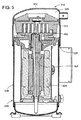
本発明の一の実施の形態は、その内部においてスクロール圧縮機組立体14が駆動ユニット16により駆動されるように設けられた外側ハウジング12を備えるスクロール圧縮機アセンブリ10として説明図に示される。スクロール圧縮機アセンブリは、流体の圧縮が望まれる冷蔵、産業用の冷却、冷凍、空調その他の適切な用途のために、冷媒回路中に配置してもよい。外側ハウジング12を貫通する冷媒流入ポート18と冷媒流出ポート20とを有する冷媒回路への接続用の適切な接続ポートが設けられる。スクロール圧縮機アセンブリ10は、スクロール圧縮機組立体14を作動させるために駆動ユニット16を駆動することにより、冷媒流入ポート18から流入し、圧縮された高圧の状態で冷媒流出ポート20から流出する適切な冷媒または他の流体の圧縮をおこなう。
One embodiment of the present invention is shown in the illustration as a
外側ハウジング12は、様々な形に設けることができる。好ましい実施の形態において、外側ハウジングは、複数のシェルセクション、好ましくは3つのシェルセクション、すなわち円筒状の中央ハウジングセクション24と、上端ハウジングセクション26と、下端ハウジングセクション28とを有する。好ましくは、ハウジングセクション24、26、28は適切な鋼板で成形され、互いに溶接されて外側ハウジング12の恒久的な筺体を形成する。あるいは、ハウジングの分解が望ましい場合には、金属鋳造部品または機械加工部品により構成された他のハウジングの構成とすることができる。
The
中央ハウジングセクション24は、好ましくは円筒状であり、上端ハウジングセクション26および下端ハウジングセクション28と入れ子に重なり合う(telescopically interfit)。これにより、スクロール圧縮機組立体14と駆動ユニット16とを収容する密閉チャンバ30が形成される。上端ハウジングセクション26および下端ハウジングセクション28はそれぞれ略ドーム形に設けられ、中央セクション24と嵌合して外側ハウジング12の上端および下端を閉じるために、それぞれが円筒状の側壁部32、34を有している。図1から分かるように、上側の側壁部32は、中央ハウジングセクション24と入れ子に重なり合い、円形の溶接部を形成するように中央ハウジングセクション24の上端において外側から溶接される。同様に、下端ハウジングセクション28の下側の側壁部34は、中央ハウジングセクション24と入れ子に重なり合い(但し、中央ハウジングセクション24の外側ではなく内側に挿入されるように図示されている)、円形の溶接部を形成するように、外側から溶接される。
The
駆動ユニット16は、好ましくは、上側の軸受部材42および下側の軸受部材44に支持された電動モータアセンブリ40の形態をとるものとしてもよい。モータアセンブリ40は、駆動シャフト46を回転駆動するように動作可能である。電動モータアセンブリ40は一般に、外側の環状のモータハウジング48と、電気コイルを備えるステータ50と、駆動シャフト46と結合して共に回転するロータ52とを有する。ステータ50にエネルギーを加えると、ロータ52が回転駆動され、それによって駆動シャフト46が中心軸54の周りを回転する。
The drive unit 16 may preferably take the form of an
図1および図4を参照すると、下側の軸受部材44は、中央ブシュと開口とを有する略円筒状の中央ハブ58を含み、駆動シャフト46を回転自在に軸支する円筒軸受60を提供する。複数の支持アーム62、典型的には少なくとも3本のアームが、好ましくは等角度間隔で軸受を提供する中央ハブ58から半径方向の外側方向に突出する。これらの支持アーム62は、下端ハウジングセクション28の下側の側壁部34の円形の終端縁部により設けられた円形の着座面64に係合し、これに着座する。このように、下端ハウジングセクション28は、下側の軸受部材44を位置決めし、支持し、着座させる機能を果たすことができ、それによりスクロール圧縮機アセンブリの内部の構成要素を支持する基部としての機能を果たす。
Referring to FIGS. 1 and 4, the lower bearing
一方、下側の軸受部材44は、下側の軸受部材44の板状の外延部68に形成された円形の座部66によって円筒状のモータハウジング48を支持するように設けられ、板状の外延部68は中央ハブ58の上端に沿って外方に突出するように設けられる。また、支持アーム62は、中央ハウジングセクションの内径に対して精密な許容差を設定されるのが好ましい。アーム62は、下側の軸受部材44が中央に位置するように中央ハウジングセクション24の内径面に係合し、それにより中心軸54の位置を維持するものとしてもよい。このことは、下側の軸受部材44と外側ハウジング12との間の締りばめおよびプレスばめによる支持の設定によってなされてもよい(例えば図4を参照)。代替として、図1に示すようなさらに好ましい構成によれば、下側の軸受は下端ハウジングセクション28と係合し、下端ハウジングセクション28は次いで中央セクション24に取り付けられる。同様に、外側のモータハウジング48を、下側の軸受部材44の段付きの座部66に沿って、締りばめおよびプレスばめによって支持してもよい。図示するように、モータハウジングを下側の軸受部材44へ確実に締着するためにネジを使用してもよい。
On the other hand, the
駆動シャフト46には、中心軸54と同軸に直径が次第に小さくなる複数の部分46a〜46dが形成されている。最小の直径部分46dは下側の軸受部材44の内において回転自在に支持され、次に小さい直径部分46cは、駆動シャフト46を下側の軸受部材44で軸方向に支持するための段部72を有している。最大の直径部分46aは、上側の軸受部材42の内において回転自在に支持される。
The
駆動シャフト46は、中心軸54に対してオフセットして設けられるオフセット軸の周りに円筒状の駆動面75を有するオフセット偏心駆動セクション74をさらに含む。このオフセット駆動セクション74は、スクロール圧縮機組立体14の可動スクロール部材のキャビティ内に軸支され、駆動シャフト46が中心軸54の周りを回転する際に、スクロール圧縮機組立体の可動部材が軌道経路を周回するように駆動する。外側ハウジング12の底端部には、これらの軸受面の全てを潤滑するために、好適な油性潤滑剤を有する潤滑剤槽76が設けられている。駆動シャフト46は、油性潤滑剤パイプとインペラ78とを有し、インペラ78は駆動シャフトの回転時にオイルポンプとして機能することにより、潤滑剤槽76から、駆動シャフト46内に画成された内部の潤滑剤通路80へ潤滑油を吐出する。駆動シャフト46の回転中に遠心力が作用し、重力の作用に抗して、潤滑油は潤滑剤通路80を通って上方へ導かれる。潤滑剤通路80は、図示のような多様な放射状の通路を含み、遠心力によって適切な軸受面にオイルを送り込んで、所望されるように摺動面を潤滑する。
The
上側の軸受部材42は中央の軸受ハブ84を有し、ハブ84の内部において、駆動シャフト46の最大の直径部分46aが回転自在に軸支される。軸受ハブ84から外方に延びるのは、外周の支持リム88に連結する支持ウェブ86である。支持ウェブ86に沿って環状段付の着座面90が設けられ、着座面90は円筒状のモータハウジング48の上端と締りばめおよびプレスばめされることにより、軸方向および半径方向に位置決めがなされる。また、上側の軸受部材42にモータハウジング48をネジで締着してもよい。外周の支持リム88も、外側ハウジング12と締りばめおよびプレスばめされる外側の環状段付の着座面92を有してもよい。例えば、外周のリム88は、軸方向において着座面92と係合する。すなわち、直径方向ではなく、軸54と直交する横断面上において係合されることとなる。中心に位置決めするために、中央ハウジングセクション24と支持リム88との間の着座面92の直下には径方向の嵌め合い部が設けられる。具体的には、入れ子になっている中央ハウジングセクション24と上端ハウジングセクション26との間には、上側の軸受部材42の外側における環状段付の着座面92と共に軸方向および半径方向において内部で位置決めをおこなう、環状の段付領域94が画成される。
The
上側の軸受部材42はまた、軸方向のスラスト面96を介した軸受支持により、可動スクロール部材に対する軸方向のスラストの支持を提供する。これは単一の構成要素によって一体的に提供されてもよいが、環状段付の接合部100に沿う上側の軸受部材42の上部と嵌合する別体のカラー部材98によって図示のように提供されている。カラー部材98は中央開口部102を画成する。この中央開口部の大きさは、オフセット偏心駆動セクション74を受け入れ、可動スクロール圧縮部材112の収容部に与えられるオフセット偏心駆動セクション74の偏心軌道運動を十分に許容する大きさに設けられている。
The
スクロール圧縮機組立体14に戻ってさらに詳細に説明すると、スクロール圧縮機組立体は、好ましくは静止した固定スクロール圧縮機体110および可動スクロール圧縮機体112により構成される、第1および第2のスクロール圧縮機体によって提供される。可動スクロール圧縮機体112は、冷媒を圧縮するために、固定スクロール圧縮機体110に対して相対的に軌道運動をおこなうように構成される。固定スクロール圧縮機体は、板状の基部116から軸方向に突出する、渦巻形状に設けられた第1のリブ114を有する。同様に、第2の可動スクロール圧縮機体112は、板状の基部120から軸方向に突出する、同様に渦巻形状に設けられた第2のスクロールリブ118を有する。スクロールリブ114、118は互いに係合し、それぞれが他方の圧縮機体112、110の各々の基部(の面)120、116とシール状態において当接する。その結果、複数の圧縮チャンバ122が、圧縮機体112、110のスクロールリブ114、118と基部120,116との間に形成される。複数のチャンバ122内では、冷媒が漸次に圧縮される。冷媒は、半径方向の外側領域における、スクロールリブ114、118を包囲する流入エリア124を介して、低い初期の圧力において流れる(例えば、図2および図3を参照)。チャンバ122内における漸次の圧縮に続いて(チャンバが漸次に半径方向の内側方向に向けて画成されていくにつれて)、固定スクロール圧縮機体110の基部116の中央に画成された圧縮出口126を通して冷媒が流出する。高圧に圧縮された冷媒は、スクロール圧縮機組立体の運転中に圧縮出口126を通ってチャンバ122から流出できる。
Returning to the
可動スクロール圧縮機体112は、駆動シャフト46の偏心オフセット駆動セクション74と係合する。より具体的には、可動スクロール圧縮機体112の収容部は、内部に設けられる摺動支持面によって偏心オフセット駆動セクション74を摺動可能に収容する、円筒状のブシュである駆動ハブ128を有する。詳細には、オフセット偏心駆動セクション74は、駆動シャフト46が中心軸54を中心として回転する間、中心軸54を中心とする軌道経路を周回する可動スクロール圧縮機体112を運動させるために、円筒状の駆動ハブ128に係合する。このオフセット関係が中心軸54に対する重量の不均衡を招くことを考慮すると、本アセンブリは、決められた角度配向において駆動シャフト46に装着される釣り合い重錘130を備えることが好ましい。釣り合い重錘130は、偏心オフセット駆動セクション74と、軌道経路を周回して駆動される可動スクロール圧縮機体112とが招く重量不均衡を相殺するように機能する(例えば、スクロールリブはとりわけ不均衡である)。釣り合い重錘130は、取付けカラー132とオフセット重量部134とを有し(図2に一番良く示されている釣り合い重錘を参照のこと)、オフセット重量部134は、釣り合い効果をもたらすことにより、均衡するように下側の釣り合い重錘135と協働して、中心軸54周りにおける回転要素の総重量を釣り合わせる。これにより、慣性力を内部において釣り合わせる、または相殺することにより、アセンブリ全体の振動および騒音を軽減することができる。
The movable
図1から図3まで、特には図2を参照すると、スクロール圧縮機組立体の運動をガイドする様子を見ることができる。固定スクロール圧縮機体110に対する可動スクロール圧縮機体112の軌道運動をガイドするために、適切なキー継手140を設けてもよい。キー継手は、スクロール圧縮機の分野では「オルダム継手」と称されることが多い。この実施の形態において、キー継手140は外側のリング体142を有し、また第1の横軸146に沿って直線的に離間する2つの第1のキー144を有し、第1のキー144は、同じく第1の軸146に沿って直線的に離間して整列する2つのキー溝トラック148のそれぞれの内部に近接するとともに、かつ直線的に摺動するように構成されている。キー溝トラック148は、第1の横軸146に沿うキー継手140の直線運動が外側ハウジング12に対する相対的な直線運動であるとともに、中心軸54に対する垂直運動となるように、静止した固定スクロール圧縮機体110によって画成される。キーは、スロット、溝、または、図示するようにキー継手140のリング体142から突出する突起により構成することができる。この第1の横軸146上における運動を制御することが、可動スクロール圧縮機体112の全軌道経路の一部をガイドすることとなる。
With reference to FIGS. 1-3, and in particular with reference to FIG. 2, it can be seen that the movement of the scroll compressor assembly is guided. Appropriate
キー継手は4つの第2のキー152をさらに有し、対向する第2のキー152の対向する対は、第1の横軸146に直交する第2の横軸154に対して実質的に平行且つ直線状に整列する。第2のキー152の2対のセットは、突出する摺動ガイド部156(ガイドフランジ部)を受け入れるように協働し、摺動ガイド部156(ガイドフランジ部)は、可動スクロール圧縮機体112の両側の基部120から突出している。摺動ガイド部156(ガイドフランジ部)は、第2のキー152のセットによる摺動ガイド部156(ガイドフランジ部)の直線的なガイド運動によって直線的に係合して摺動し、交差する第2の横軸に沿って直線移動するようにガイドされる。
The key coupling further includes four
キー継手140により、第1の横軸146および交差する第2の横軸154に沿って、固定スクロール圧縮機体110に対する可動スクロール圧縮機体112の相対的な動きが拘束される。その結果、可動スクロール圧縮機体の平行運動のみが許容されるため、可動スクロール圧縮機体の相対的な回転は防止される。より具体的には、固定スクロール圧縮機体110は、キー継手140の動きを第1の横軸146に沿う直線運動に制限し、一方で、キー継手140は、第1の横軸146に沿って運動する際に、第1の横軸146に沿って可動スクロール圧縮機体112を担持する。さらに、可動スクロール圧縮機体は、第2のキー152によって受け止められて、それらの間を摺動する摺動ガイド部156(ガイドフランジ部)によってもたらされる相対的な摺動により、交差する第2の横軸154に沿ってキー継手140に対して独立して動くことができる。互いに直交する2つの軸146、154における同時運動が可能であるので、可動スクロール圧縮機体112の円筒状の駆動ハブ128の上において、駆動シャフト46の偏心オフセット駆動セクション74によってもたらされる偏心運動は、固定スクロール圧縮機体110に対する可動スクロール圧縮機体112の軌道経路上における相対的な運動に変換される。
The key joint 140 restrains the relative movement of the movable
固定スクロール圧縮機体110をさらに詳細に参照すると、この圧縮機体110は、上側の軸受部材42との間を軸方向および鉛直方向に延びて、可動スクロール圧縮機体112の外周を延在する延長部によって、上側の軸受部材42に固定される。図示の実施の形態において、固定スクロール圧縮機体110は、スクロールリブと同じ側において基部116から突出する、軸方向に突出する複数の脚部158を有する(図2を参照のこと)。これらの脚部158は、上側の軸受部材42の上面に係合し、これに着座する。好ましくは、固定スクロール圧縮機体110を上側の軸受部材42に締着するために、ボルト160(図2参照)が設けられる。各ボルト160は、固定スクロール圧縮機体の脚部158を軸方向に貫通して延在し、上側の軸受部材42の対応するネジ穴に締結される。固定スクロール圧縮機体110をさらに支持して固定するために、固定スクロール圧縮機体の外周は、外側ハウジング12の円筒面の内側に密着して受け入れられる円筒状の表面162を有する。表面162と側壁32との間には隙間を有するために、圧縮機アセンブリを覆う上端ハウジングセクション26の組み付け、およびひいてはO−リングシール164の内蔵が可能となる。O−リングシール164は、圧縮された高圧の流体から外側ハウジング12内の非圧縮部/潤滑剤槽部までの経路における洩れを防ぐために、円筒状の位置決め表面162と外側ハウジング12との間の領域を密封する。半径方向の外側に面する環状溝166内にシール164は保持される。
Referring to the fixed
図1から図3まで、特に図3を参照すると、固定スクロール110の上側(スクロールリブの反対側)には、浮動バッフル部材170が支持されている。バッフル部材170を収容するために、固定スクロール圧縮機体110の上側は環状を成し、さらに詳細には、円筒状の内側のハブ領域172と、その外側において離間する外周のリム領域174とを有し、ハブ領域172と外周のリム領域174とは、基部116の半径方向に延びるディスク領域176を介して連結されている。ハブ172とリム174との間には、バッフル部材170が収容される環状のピストン型のチャンバ178が設けられている。この構成により、バッフル部材170と固定スクロール圧縮機体110との組合せが、外側ハウジング12内において低圧領域から高圧チャンバ180を隔てるように機能する。バッフル部材170が固定スクロール圧縮機体110の外周のリム174と係合し、その内側で半径方向に拘束されている状態が図示されているが、バッフル部材170は代替として、外側ハウジング12の内面へ直に接して、円筒状に位置決めすることもできる。
Referring to FIGS. 1 to 3, particularly FIG. 3, a floating
この実施の形態で示すように、そして特に図3を参照すると、バッフル部材170は、内側のハブ領域184と、ディスク領域186と、外周のリム領域188とを有する。強度の向上のために、ハブ領域184と外周のリム領域188との間のディスク領域186の上面に沿って半径方向に延在する複数のリブ190を一体的に設けるものとしてもよく、複数のリブ190は、好ましくは、中心軸54に対して等角度間隔に配置される。バッフル部材170は、高圧チャンバ180を外側ハウジング12の残りの部分から分離する機能に加えて、高圧チャンバ180で生じた圧力負荷を、固定スクロール圧縮機体110の内側の領域から固定スクロール圧縮機体110の外周の領域へ向けて伝達するように機能する。外周の領域において、圧力負荷は外側ハウジング12へ伝達され、外側ハウジング12においてより直接的に担持される。従って、構成要素に生ずる応力を実質的に回避または少なくとも最小限に抑え、スクロール圧縮機体のような作動部材の変形または撓みを実質的に回避できる。好ましくは、バッフル部材170は、固定スクロール圧縮機体110に対しては、内周の領域に沿って相対的に浮動可能に設けられる。これは、例えば、図示の実施の形態に示すように、固定スクロール圧縮機体およびバッフル部材の、各々のハブ領域に沿った互いに円筒状の摺動面間の円筒状に摺動する接合部192によって達成できる。高圧チャンバ180内の圧縮された高圧の冷媒はバッフル部材170に作用するために、摩擦係合による場合を除き、内側の領域に沿って負荷が伝達されることは実質的にないだろう。その代わりに、固定スクロール圧縮機体110およびバッフル部材170のそれぞれのリム領域が設置される半径方向の外周に、軸方向におけるリング状の接触部194が設けられる。好ましくは、バッフル部材170の最内部の直径部分と固定スクロール圧縮機体110の上側との間に環状の軸方向の隙間196を設ける。環状の軸方向の隙間196は、バッフル部材の半径方向の最内部とスクロール部材との間に画成され、高圧チャンバ180内で圧縮される高圧の冷媒によって生じる圧力負荷に応じてサイズを縮小するように構成される。隙間196は、圧力および荷重が除去された際には、弛緩状態におけるサイズにまで拡大可能である。
As shown in this embodiment, and with particular reference to FIG. 3,
負荷の伝達をさらに効果的に可能とするために、環状の中間圧または低圧チャンバ198がバッフル部材170と固定スクロール圧縮機体110との間に画成される。この中間圧または低圧チャンバは、(例えば、個別の圧縮チャンバ122の一つを固定スクロール圧縮機体を介して画成される流体連通路を通して中間圧または低圧チャンバ198に接続するために、)図示のように低い吸引圧に曝されるか、または中間圧に曝され得る。従って、負荷担持特性は、最良の応力/撓み設定のために選択された低圧または中間圧に基づいて構成され得る。いずれの場合でも、運転中の中間圧または低圧チャンバ198内部の圧力は高圧チャンバ180内部の圧力よりも実質的に低く、それによりバッフル部材170にかかる圧力差および負荷が生じる。
An annular intermediate or
洩れを防ぎ、負荷の伝達をさらに可能とするために、内側および外側のシール204、206を設けてもよく、シール204、206は弾性を有するO−リングシール部材であってもよい。内側シール204は、好ましくは半径方向におけるシール(radial seal)であり、バッフル部材170の内径に沿って画成される半径方向の内側に面する内側溝208内に配設される。同様に、外側のシール206は、外周のリム領域188にバッフル部材170の外径に沿って画成される、半径方向の外側に面する外側溝210内に配設される。半径方向におけるシールを外側の領域に設けて示しているが、代替としてまたは追加として、軸方向におけるシールを軸方向に設けられるリング状の接合部194に沿って設けるものとしてもよい。
Inner and
バッフル部材170は打抜プレス加工された鋼製の部品によるものであってもよいが、好ましくは、図示のように、先に述べた構造的な特性を有するように、拡張された機能をもたらす鋳造および/または機械加工による部材(アルミニウムであってもよい)により構成される。この方式でバッフル部材を作成することにより、かかるバッフルの重負荷打抜プレス加工を回避できる。
The
さらに、バッフル部材170を固定スクロール圧縮機体110に保持することができる。具体的には、図から分かるように、バッフル部材170の内側のハブ領域184の半径方向の内側に突出する環状フランジ214が、ストップ板212と固定スクロール圧縮機体110との間で軸方向に捕捉される。ストップ板212は、ボルト216によって固定スクロール圧縮機体110に締結される。ストップ板212は、固定スクロール圧縮機体110の内側のハブ172の上方で半径方向に突出する外延218を有する。ストップ板の外延218は、バッフル部材170のストッパ兼リテーナとして機能する。この方式における、ストップ板212の役割は、バッフル部材170が固定スクロール圧縮機体110に担持されるように、バッフル部材170を固定スクロール圧縮機体110に保持することである。
Further, the
図示のように、ストップ板212は、逆止弁220の一部を成す。逆止弁は、内側のハブ172の内部において固定スクロール圧縮機体の出口エリアに画成されるチャンバ内に収容された可動バルブプレート要素222を有する。ストップ板212は、従って、可動バルブプレート要素222が内部に配置された逆止弁チャンバ224を閉鎖する。逆止弁チャンバ内には、中心軸54に沿って逆止弁220の動きをガイドする、円筒状のガイド壁面226が設けられる。凹部228がガイド壁226の上側の部分に設けられて、可動バルブプレート要素222が弁座230から離れてリフトされる際に、圧縮された冷媒が逆止弁を通過できるように構成される。開口232がストップ板212に設けられ、スクロール圧縮機組立体から高圧チャンバ180への圧縮ガスの通過を可能とする。逆止弁は、スクロール圧縮機組立体が作動しているときに、可動バルブプレート要素222がその弁座230から離されることによって、圧縮された冷媒が圧縮出口126を通ってスクロール圧縮機組立体から流出できるよう、一方向における流れを許容するように作動する。しかし、駆動ユニットが停止し、スクロール圧縮機組立体が作動を中断すると、高圧チャンバ180内の高圧は可動バルブプレート要素222を弁座230に押し戻す。これにより逆止弁220が閉鎖し、それによってスクロール圧縮機組立体を介する圧縮された冷媒の逆流が防止される。
As shown, the
作動中、スクロール圧縮機アセンブリ10は、ハウジングの流入ポート18で低圧の冷媒を受け入れ、ハウジングの流出ポート20を介して冷媒が流出可能に設けられた高圧チャンバ180へ送り出すために、冷媒を圧縮するように作動する。図4に示すように、内部導管234は、流入ポート18からモータハウジングの入口238を介して、モータハウジング48へ低圧の冷媒を導くことができるように、外側ハウジング12の内側において接続可能に設けられる。このことはモータを横切る低圧の冷媒の流れを可能とするものであり、それにより、モータの運転によって生ずるモータからの熱を冷却および除去することができる。続いて、低圧の冷媒は、モータハウジングを長手方向に、上端に向かって内部の空間を通過するとともに、低圧の冷媒は、中心軸54の周りに等角度間隔で配置された複数のモータハウジングの出口240(図2を参照)を通って流出可能に設けられている。モータハウジングの出口240は、モータハウジング48の内に、上側の軸受部材42の内に、またはモータハウジングと上側の軸受部材との組合せによって(例えば、図2に示すように、それらの間に形成された隙間によって)画成されてもよい。モータハウジングの出口240から流出すると、低圧の冷媒はモータハウジングと外側ハウジングとの間に形成された環状チャンバ242に流入する。そこから、低圧の冷媒は、図3に示すように、上側の軸受部材42と外側ハウジング12との間に隙間を形成するために上側の軸受部材42の両側の凹部によって画成される、一対の対向する外周の貫通ポート244を通過して、上側の軸受部材を通過できる。貫通ポート244は、モータハウジングの出口240に対して角度を隔てて配置されてもよい。上側の軸受部材42を通過すると、低圧の冷媒は最終的にスクロール圧縮機体110、112の流入エリア124に入る。流入エリア124から、低圧の冷媒は、最終的に両側のスクロールリブ114、118(固定スクロール圧縮機体のそれぞれの側に1つずつ設けられた流入口)に入り、チャンバ122によって漸進的に圧縮されて圧縮出口126において最大の圧縮状態に達し、続いて逆止弁220を通過して高圧チャンバ180に流入する。そこから、高圧に圧縮された冷媒は、スクロール圧縮機アセンブリ10からハウジングの冷媒流出ポート20を通過して流出する。
In operation, the
本発明によると、図1から図4までに示す第1の実施の形態は、上側のハウジングセクション26が円筒状の中央のハウジングセクション24上を下方に摺動可能な程度を制限する停止制限を提供する。この停止制限は、固定スクロール圧縮機体110のリム174により提供されるか、あるいは代替として、(例えば、上側のハウジングセクションの円筒状の壁の内側の僅かに傾斜する面と相互作用する)固定スクロール圧縮機体110の外周部により提供される、軸方向における上側の当接縁部であってもよい。いずれの場合も、この第1の実施の形態における固定スクロール圧縮機体110は、上側のシェルハウジングセクション26が円筒状の中央のハウジングセクション24上を軸方向において摺動可能な程度を制限する停止制限を提供するように機能するが、これによって、両ハウジングセクションを入れ子に嵌合するときに、円周溶接が施される部位を制限する。これはまた、固定スクロール圧縮機体と上側のシェルセクションとの間に形成される、高圧チャンバ180のために所定の容量のチャンバを画成するように機能する。
In accordance with the present invention, the first embodiment shown in FIGS. 1-4 provides a stop limit that limits the degree to which the
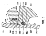
スクロール圧縮機アセンブリ310の代替の実施の形態を図5から図7までに示す。この実施の形態は、固定スクロール圧縮機体312と上側のハウジングシェルセクション314との間に構成上の特徴、すなわち中間(中央)のハウジングシェルセクション316の円筒状の壁に対しても相対的に、上側のハウジングシェルセクション314を位置決めするという特徴、を追加する点を除いて、第1の実施の形態に大きく類似する。したがって、これらの相違点に焦点を当てることにする。ただし、この実施の形態も同様に、入れ子に嵌合する複数のシェルセクションから成る外側ハウジング318と、電動モータ320を含んで設けられる駆動ユニットと、駆動シャフト324を介して電動モータ320により駆動される可動スクロール圧縮機体322とを含み、可動スクロール圧縮機体322と固定スクロール圧縮機体312との相対的な運動を可能として、高圧チャンバ326への冷媒の圧縮を可能とすることを指摘しておく。
An alternative embodiment of the
本発明によれば、この実施の形態において、上側のハウジングシェルセクション314は、固定スクロール圧縮機体312を基準として位置決めされることにより、残りのハウジング部分に対して軸方向において相対的に位置決めされる、第1の実施の形態と同様に停止制限部を設ける。好ましくは、軸方向において当接する協働して機能する段付部332、段付領域342を示す図6および図7の拡大図でより明瞭に示されるように、上側のハウジングシェルセクション314は、固定スクロール圧縮機体312と軸方向において当接することになる。上側のハウジングシェルセクション314は、中間(中央)のハウジングシェルセクション316と入れ子に嵌合し、2つのハウジングシェルセクション314、316を軸方向において正確に位置決めするために、両者間に軸方向における当接部が設けられ、それにより、これら2つのハウジングセクションを固定し、両者間を密閉してシールする円周溶接部328の軸方向における位置を決定する。
According to the present invention, in this embodiment, the upper
上記の段付領域342と協働して機能する段付部332を提供するために、固定スクロール圧縮機体は、大径部334と小径部336とを含むように段付部332により遮られる略円筒状の外周部330を含み、軸方向における当接部338は、これらの2つの部分334と336とを連接する。同様に、上側のハウジングシェルセクション314の延在する円筒状の壁領域の略円筒状の内周領域(内周部)340は、段付領域(段付部)342を含み、半径方向に延在する軸方向における当接領域(当接部)348により連接される大径領域(大径部)344と小径領域(小径部)346とを含む。軸方向における当接領域(当接部)348は、大径領域(大径部)344および小径領域(小径部)346を連接し、これらの間に略画成される(「部」は「領域」とも称され、互換的に用いられる)。対応する段付部332および段付領域342は互いを受け止め合い、対応する軸方向における当接部338および当接領域348は軸方向において係合および当接し、中間(中央)のハウジングシェルセクション316に対して相対的に上側のハウジングシェルセクション314を精確に位置決めすることにより、所定の位置に円周溶接部328を配置し、かつ高圧チャンバ326の所望の容量も定める。好ましくは、図示するように、これは追加の固定具または位置決め装置を必要とせずに実行可能である。代替として、組み立て、位置決めおよび取り付けを可能とするために、上側のハウジングシェルセクション314をスクロール圧縮機アセンブリの残り部分の上に置くものとしてもよい。
In order to provide a stepped
図示するように、固定スクロール圧縮機体312の外周部330に環状の溝350が画成され、固定スクロール圧縮機体312と上側のハウジングシェルセクション314との間をシールするためにリングシール352を環状の溝350内に着座させる。適切なシールを確保するために、そして適切な軸方向における当接を可能とするために、環状の逃げ(クリアランス)隙間354が、上側のシェルセクションの小径領域(小径部)346と固定スクロール圧縮機体の小径部336との間に画成される(例えば図6および図7を参照)。好ましくは、図示するように、溝350とリングシール352とは、上側のハウジングセクションの大径領域(大径部)344と係合する固定スクロール圧縮機体の大径部334が提供し、当接部338、当接領域348の下方に設けられる。
As shown, an
さらなる特徴は、固定スクロール圧縮機体と上側のハウジングシェルセクションとの対応する当接部338、当接領域348は、互いに係合するカム面を提供し、シェルセクションに対して固定スクロール圧縮機体を相対的に心出し(センタリング)する。このことは、図で示すように、軸方向における当接面を互いに円弧面356とすることによって達成してもよい。
A further feature is that the
上側のハウジングシェルセクション314は、金属板材料から形成されるのが好ましい。直径が異なる大径領域344、小径領域346を好適に設けることができるように、金属板材料の厚さを、図6および図7に示すように変更して設けることにより、段付領域342を好適に設け、これを形成してもよい。具体的には、プレス成形に加えて任意の機械仕上げをおこなうことにより、大径領域344および小径領域346を設けることができ、それにより段付領域342を形成する。さらに、固定スクロール圧縮機体312の段付部332を、所望するように、異なる圧縮機ごとに上側のシェルセクションを異なる位置に配置できるように、異なるモデルまたは異なるスクロール圧縮機の設計ごとに、異なる軸方向における位置に機械加工により設けることが可能である。例えば、当接部338をさらに高い位置に機械加工により設けることで、上側のシェルセクションをさらに高い位置に持ち上げることができる。
The upper
本明細書中で引用する公報、特許出願および特許を含むすべての文献は、各文献を個々に、具体的に示し、引用して組み込むかのように、また、その全体を本明細書に記載するかのように、引用して組み込まれる。 All publications, publications, patent applications and patents cited herein are hereby expressly incorporated herein in their entirety, as if each reference was specifically and individually listed and incorporated by reference. Incorporated as if to quote.
本発明の説明に関連して(特に以下の請求項に関連して)用いられる名詞及び同様な指示語の使用は、本明細書中で特に指摘したり、明らかに文脈と矛盾したりしない限り、単数および複数の両方に及ぶものと解釈される。語句「備える」、「有する」、「含む」および「包含する」は、特に断りのない限り、オープンエンドターム(すなわち「〜を含むが限らない」という意味)として解釈される。本明細書中の数値範囲の具陳は、本明細書中で特に指摘しない限り、単にその範囲内に該当する各値を個々に言及するための略記法としての役割を果たすことだけを意図しており、各値は、本明細書中で個々に列挙されたかのように、明細書に組み込まれる。本明細書中で説明されるすべての方法は、本明細書中で特に指摘したり、明らかに文脈と矛盾したりしない限り、あらゆる適切な順番で行うことができる。本明細書中で使用するあらゆる例または例示的な言い回し(例えば「など」)は、特に主張しない限り、単に本発明をよりよく説明することだけを意図し、本発明の範囲に対する制限を設けるものではない。明細書中のいかなる言い回しも、請求項に記載されていない要素を、本発明の実施に不可欠であるものとして示すものとは解釈されないものとする。 The use of nouns and similar directives used in connection with the description of the present invention (especially in connection with the claims below) is not specifically pointed out herein or clearly contradicted by context. , And construed to cover both singular and plural. The phrases “comprising”, “having”, “including” and “including” are to be interpreted as open-ended terms (ie, meaning “including but not limited to”), unless otherwise specified. The use of numerical ranges in this specification is intended only to serve as a shorthand for referring individually to each value falling within that range, unless otherwise indicated herein. Each value is incorporated into the specification as if it were individually listed herein. All methods described herein can be performed in any suitable order unless otherwise indicated herein or otherwise clearly contradicted by context. Any examples or exemplary phrases used herein (eg, “etc.”) are intended only to better describe the invention, unless otherwise stated, and to limit the scope of the invention. is not. No language in the specification should be construed as indicating any non-claimed element as essential to the practice of the invention.
本明細書中では、本発明を実施するため本発明者が知っている最良の形態を含め、本発明の好ましい実施の形態について説明している。当業者にとっては、上記説明を読めば、これらの好ましい実施の形態の変形が明らかとなろう。本発明者は、熟練者が適宜このような変形を適用することを期待しており、本明細書中で具体的に説明される以外の方法で本発明が実施されることを予定している。従って本発明は、準拠法で許されているように、本明細書に添付された請求項に記載の内容の修正および均等物をすべて含む。さらに、本明細書中で特に指摘したり、明らかに文脈と矛盾したりしない限り、すべての変形における上記要素のいずれの組合せも本発明に包含される。 In the present specification, preferred embodiments of the present invention are described, including the best mode known to the inventors for carrying out the invention. Variations of these preferred embodiments will become apparent to those skilled in the art after reading the above description. The present inventor expects skilled workers to apply such modifications as appropriate, and intends to implement the present invention in a manner other than that specifically described herein. . Accordingly, this invention includes all modifications and equivalents of the subject matter recited in the claims appended hereto as permitted by applicable law. Moreover, any combination of the above-described elements in all variations thereof is encompassed by the invention unless otherwise indicated herein or otherwise clearly contradicted by context.
10 スクロール圧縮機アセンブリ
12 外側ハウジング
14 スクロール圧縮機組立体
16 駆動ユニット
18 冷媒流入ポート
20 冷媒流出ポート
24 中央ハウジングセクション
26 上端ハウジングセクション
28 下端ハウジングセクション
30 密閉チャンバ
32 側壁部(上端ハウジングセクション)
34 側壁部(下端ハウジングセクション)
40 電動モータアセンブリ
42 軸受部材(上側)
44 軸受部材(下側)
46 駆動シャフト(電動モータアセンブリ)
46a (最大)直径部分(駆動シャフト)
46b 直径部分(駆動シャフト)
46c 直径部分(駆動シャフト)
46d (最小)直径部分(駆動シャフト)
48 モータハウジング(電動モータアセンブリ)
50 ステータ(電気コイル)(電動モータアセンブリ)
52 ロータ(電動モータアセンブリ)
54 中心軸
58 中央ハブ(軸受部材(下側))
60 円筒軸受(軸受部材(下側))
62 支持アーム(軸受部材(下側))
64 着座面(下端ハウジングセクション)
66 座部(軸受部材(下側))
68 外延部(軸受部材(下側))
72 段部(駆動シャフト)
74 オフセット偏心駆動セクション
75 駆動面(オフセット偏心駆動セクション)
76 潤滑剤槽
78 インペラ(駆動シャフト)
80 潤滑剤通路(駆動シャフト)
84 軸受ハブ(軸受部材(上側))
86 支持ウェブ(軸受部材(上側))
88 支持リム(軸受部材(上側))
90 着座面(軸受部材(上側))
92 着座面(軸受部材(上側))
94 段付領域(上側/中央ハウジングセクション)
96 スラスト面(カラー部材)
98 カラー部材
100 接合部(カラー部材)
102 中央開口部(カラー部材)
110 固定スクロール圧縮機体(スクロール圧縮機組立体)
112 可動スクロール圧縮機体(スクロール圧縮機組立体)
114 第1のスクロールリブ(固定スクロール圧縮機体)
116 基部(固定スクロール圧縮機体)
118 第2のスクロールリブ(可動スクロール圧縮機体)
120 基部(可動スクロール圧縮機体)
122 圧縮チャンバ
124 流入エリア
126 圧縮出口(固定スクロール圧縮機体)
128 駆動ハブ(可動スクロール圧縮機体)
130 釣り合い重錘(上側)
132 取付けカラー(釣り合い重錘(上側))
134 オフセット重量部(釣り合い重錘(上側))
135 釣り合い重錘(下側)
140 キー継手(オルダム継手)
142 リング体(キー継手)
144 第1のキー(キー継手)
146 第1の横軸
148 キー溝トラック(固定スクロール圧縮体)
152 第2のキー(キー継手)
154 第2の横軸
156 摺動ガイド部(可動スクロール圧縮機体)
158 脚部(固定スクロール圧縮機体)
160 ボルト
162 表面(固定スクロール圧縮機体)
164 O−リングシール
166 環状溝(固定スクロール圧縮機体)
170 浮動バッフル部材
172 ハブ領域(固定スクロール圧縮機体)
174 リム領域(固定スクロール圧縮機体)
176 ディスク領域(固定スクロール圧縮機体)
178 ピストン型チャンバ
180 高圧チャンバ
184 ハブ領域(浮動バッフル部材)
186 ディスク領域(浮動バッフル部材)
188 リム領域(浮動バッフル部材)
190 リブ(浮動バッフル部材)
192 接合部
194 接合部
196 隙間
198 中間圧(低圧)チャンバ
204 O−リングシール
206 O−リングシール
208 内側溝(浮動バッフル部材)
210 外側溝(浮動バッフル部材)
212 ストップ板
214 環状フランジ(浮動バッフル部材)
216 ボルト
218 外延(ストップ板)
220 逆止弁
222 可動バルブプレート要素(逆止弁)
224 逆止弁チャンバ(逆止弁)
226 ガイド壁面(逆止弁)
228 凹部(逆止弁)
230 弁座(逆止弁)
232 開口(ストップ板/逆止弁)
234 内部導管
238 入口(モータハウジング)
240 出口(モータハウジング)
242 環状チャンバ
244 貫通ポート(軸受部材(上側))
310 スクロール圧縮機アセンブリ
312 固定スクロール圧縮機体(スクロール圧縮機組立体)
314 上端ハウジングセクション
316 中央ハウジングセクション
318 外側ハウジング
320 電動モータ(駆動ユニット)
322 可動スクロール圧縮機体(スクロール圧縮機組立体)
324 駆動シャフト
326 高圧チャンバ
328 円周溶接部
330 外周部(固定スクロール圧縮機体)
332 段付部(固定スクロール圧縮機体)
334 大径部(固定スクロール圧縮機対)
336 小径部(固定スクロール圧縮機体)
338 当接部(固定スクロール圧縮機体)
340 内周領域(内周部)(上端ハウジングセクション)
342 段付領域(段付部)(上端ハウジングセクション)
344 大径領域(大径部)(上端ハウジングセクション)
346 小径領域(小径部)(上端ハウジングセクション)
348 当接領域(当接部)(上端ハウジングセクション)
350 溝(固定スクロール圧縮機体)
352 リングシール(固定スクロール圧縮機体、上端ハウジングセクション)
354 隙間(固定スクロール圧縮機体、上端ハウジングセクション)
356 円弧面(固定スクロール圧縮機体、上端ハウジングセクション)
DESCRIPTION OF
34 Side wall (lower housing section)
40
44 Bearing member (lower side)
46 Drive shaft (electric motor assembly)
46a (maximum) diameter part (drive shaft)
46b Diameter part (drive shaft)
46c Diameter part (drive shaft)
46d (minimum) diameter part (drive shaft)
48 Motor housing (electric motor assembly)
50 Stator (Electric coil) (Electric motor assembly)
52 Rotor (Electric motor assembly)
54
60 Cylindrical bearing (bearing member (lower side))
62 Support arm (bearing member (lower side))
64 Seating surface (lower housing section)
66 Seat (Bearing member (lower side))
68 Extension part (bearing member (lower side))
72 steps (drive shaft)
74 Offset
76
80 Lubricant passage (drive shaft)
84 Bearing hub (Bearing member (upper side))
86 Support web (bearing member (upper side))
88 Support rim (bearing member (upper side))
90 Seating surface (bearing member (upper side))
92 Seating surface (Bearing member (upper side))
94 Stepped area (upper / central housing section)
96 Thrust surface (colored member)
98
102 Central opening (collar member)
110 Fixed scroll compressor body (scroll compressor assembly)
112 Movable scroll compressor body (scroll compressor assembly)
114 First scroll rib (fixed scroll compressor body)
116 Base (fixed scroll compressor body)
118 Second scroll rib (movable scroll compressor body)
120 base (movable scroll compressor body)
122
128 Drive hub (movable scroll compressor body)
130 counterweight (upper)
132 Mounting collar (balance weight (upper))
134 Offset weight (balance weight (upper))
135 Balance weight (lower side)
140 Key Fitting (Oldham Fitting)
142 Ring body (key joint)
144 First key (key coupling)
146 First
152 Second key (key coupling)
154 Second
158 Leg (fixed scroll compressor body)
164 O-
170 Floating
174 Rim area (fixed scroll compressor body)
176 Disk space (fixed scroll compressor body)
178
186 disk area (floating baffle member)
188 Rim area (floating baffle member)
190 Rib (floating baffle member)
192
210 Outer groove (floating baffle member)
212
220
224 Check valve chamber (check valve)
226 Guide wall (check valve)
228 Concavity (check valve)
230 Valve seat (check valve)
232 Opening (stop plate / check valve)
234
240 outlet (motor housing)
242
310
314
322 Movable scroll compressor body (scroll compressor assembly)
332 Stepped part (fixed scroll compressor body)
334 Large diameter part (fixed scroll compressor pair)
336 Small diameter part (fixed scroll compressor body)
338 Contact part (fixed scroll compressor body)
340 Inner circumference area (inner circumference) (upper housing section)
342 Stepped area (stepped section) (top housing section)
344 Large-diameter region (large-diameter portion) (upper housing section)
346 Small-diameter area (small-diameter section) (upper housing section)
348 Contact area (contact section) (upper housing section)
350 groove (fixed scroll compressor body)
352 ring seal (fixed scroll compressor body, top housing section)
354 Clearance (fixed scroll compressor body, top housing section)
356 Circular surface (fixed scroll compressor body, top housing section)
Claims (27)
複数のスクロール圧縮機体であって、それぞれの基部と、前記それぞれの基部から突出して、流体を圧縮するために軸の周りにおいて互いに係合するそれぞれのスクロールリブとを有する、複数のスクロール圧縮機体と;
前記複数のスクロール圧縮機体の間の相対的な運動を可能とするように作動する、駆動ユニットとを備え;
前記シェルセクションは、前記複数のスクロール圧縮機体の1つを基準として位置決めされて、前記ハウジングの残り部分に対して、軸方向において相対的に位置決めされ;
前記複数のスクロール圧縮機体の1つと前記シェルセクションとの間をシールする、前記駆動ユニットと前記軸方向における位置決め位置との間の軸方向における位置に設けられたシールとをさらに備える;
スクロール圧縮機。 A housing containing a shell section;
A plurality of scroll compressor bodies having respective base portions and respective scroll ribs projecting from the respective base portions and engaging each other around an axis to compress fluid; and ;
A drive unit that operates to allow relative movement between the plurality of scroll compressor bodies;
The shell section is positioned relative to one of the plurality of scroll compressor bodies and is positioned axially relative to the remainder of the housing;
A seal provided at an axial position between the drive unit and the axial positioning position for sealing between one of the plurality of scroll compressor bodies and the shell section;
Scroll compressor.
略円筒状の外周部と;
半径方向に延在する当接部により連接される大径部と小径部とを含むように前記略円筒状の外周部に沿って形成される段付部とを含み;
前記シェルセクションと係合する前記当接部は、前記大径部と前記小径部との間に画成される、請求項3に記載のスクロール圧縮機。 The fixed scroll compressor body is:
A substantially cylindrical outer periphery;
A stepped portion formed along the substantially cylindrical outer peripheral portion so as to include a large diameter portion and a small diameter portion connected by a contact portion extending in the radial direction;
The scroll compressor according to claim 3, wherein the abutting portion that engages with the shell section is defined between the large diameter portion and the small diameter portion.
略円筒状の内周領域と;
半径方向に延在する当接領域により連接される大径領域と小径領域とを含むように前記略円筒状の内周領域に沿って形成される段付領域とを含み;
前記当接領域は前記大径領域と前記小径領域との間に画成され、前記固定スクロール圧縮機体の前記当接部と前記シェルセクションの前記当接領域とは互いに係合する、請求項5に記載のスクロール圧縮機。 The shell section is:
A substantially cylindrical inner peripheral region;
A stepped region formed along the substantially cylindrical inner peripheral region so as to include a large diameter region and a small diameter region connected by a contact region extending in the radial direction;
The contact region is defined between the large diameter region and the small diameter region, and the contact portion of the fixed scroll compressor body and the contact region of the shell section are engaged with each other. Scroll compressor described in 1.
略円筒状の内周領域と;
半径方向に延在する当接領域により連接される大径領域と小径領域とを含むように前記略円筒状の内周領域に沿って形成される段付領域とを含み;
前記当接領域は前記大径領域と前記小径領域との間に画成され、前記当接領域は前記固定スクロール圧縮機体と係合する、請求項3に記載のスクロール圧縮機。 The shell section is:
A substantially cylindrical inner peripheral region;
A stepped region formed along the substantially cylindrical inner peripheral region so as to include a large diameter region and a small diameter region connected by a contact region extending in the radial direction;
The scroll compressor according to claim 3, wherein the contact area is defined between the large diameter area and the small diameter area, and the contact area engages with the fixed scroll compressor body.
前記複数のスクロール圧縮機体を覆ってハウジングシェルセクションを組み付けるステップと;
前記複数のスクロール圧縮体の1つにより、前記ハウジングシェルセクションの軸方向における運動を制限するステップと;
前記ハウジングシェルセクションをハウジングの残り部分に固定するステップと;
前記ハウジングシェルセクションと前記複数のスクロール圧縮機体の1つを、前記制限の下方においてシールするステップとを備える;
スクロール圧縮機の製造方法。 Assembling a plurality of scroll compressor bodies, the plurality of scroll compressor bodies projecting from their respective bases and said respective bases and engaging each other around an axis to compress fluid Assembling a plurality of scroll compressor bodies having ribs;
Assembling a housing shell section over the plurality of scroll compressor bodies;
Limiting axial movement of the housing shell section by one of the plurality of scroll compression bodies;
Securing the housing shell section to the remainder of the housing;
Sealing the housing shell section and one of the plurality of scroll compressor bodies below the restriction;
A method for manufacturing a scroll compressor.
前記ハウジングは第2のシェルセクションをさらに含んで設けられ;
前記最上のハウジングシェルセクションの前記円筒状の側壁部分と前記第2のシェルセクションとを入れ子に嵌合するステップと;
前記最上のハウジングシェルセクションを前記第2のシェルセクションに円周溶接するステップとをさらに備える;
請求項14に記載の方法。 The housing shell section is provided as an uppermost housing shell section having an end covering portion and a cylindrical side wall portion;
The housing further includes a second shell section;
Nesting the cylindrical sidewall portion of the uppermost housing shell section and the second shell section;
Circumferentially welding the uppermost housing shell section to the second shell section;
The method according to claim 14.
前記段付領域を軸方向において当接させるステップとをさらに備える;
請求項19に記載の方法。 Forming a stepped region in both an inner peripheral region of the housing shell section and the outer peripheral portion of the one of the plurality of scroll compressor bodies;
A step of abutting the stepped region in the axial direction;
The method of claim 19.
複数のスクロール圧縮機体であって、固定スクロール圧縮機体と可動スクロール圧縮機体とを含み、それぞれの基部と、前記それぞれの基部から突出して、流体を圧縮するために軸の周りにおいて互いに係合するそれぞれのスクロールリブとを有する、複数のスクロール圧縮機体と;
前記複数のスクロール圧縮機体の間の相対的な運動を可能とするように作動する、駆動ユニットとを備え;
前記シェルセクションは、前記シェルセクションの段付領域を介して前記固定スクロール圧縮機体と軸方向において当接し、前記シェルセクションは略円筒状の内周領域を含み、前記段付領域は、前記略円筒状の内周領域に沿って形成されて、径方向に延在する当接領域によって連接する大径領域と小径領域とを含み、前記当接領域は、前記大径領域と小径領域との間に画成され、前記段付領域は、前記シェルセクションの壁の厚さを薄く設けることによって形成される;
スクロール圧縮機。 A housing containing a shell section;
A plurality of scroll compressor bodies, each including a fixed scroll compressor body and a movable scroll compressor body, each projecting from the respective base and engaging each other around an axis to compress fluid A plurality of scroll compressor bodies having a plurality of scroll ribs;
A drive unit that operates to allow relative movement between the plurality of scroll compressor bodies;
The shell section abuts the fixed scroll compressor body in an axial direction through a stepped region of the shell section, the shell section includes a substantially cylindrical inner peripheral region, and the stepped region includes the substantially cylindrical portion. A large-diameter region and a small-diameter region which are formed along the inner peripheral region of the shape and are connected by a contact region extending in the radial direction. The stepped region is formed by reducing the thickness of the wall of the shell section;
Scroll compressor.
略円筒状の外周部と;
半径方向に延在する当接部により連接される大径部と小径部とを含むように前記略円筒状の外周部に沿って形成される段付部とを含み;
前記シェルセクションと係合する前記当接部は、前記大径部と前記小径部との間に画成される、請求項22に記載のスクロール圧縮機。 The fixed scroll compressor body is:
A substantially cylindrical outer periphery;
A stepped portion formed along the substantially cylindrical outer peripheral portion so as to include a large diameter portion and a small diameter portion connected by a contact portion extending in the radial direction;
The scroll compressor according to claim 22, wherein the abutting portion that engages with the shell section is defined between the large diameter portion and the small diameter portion.
Applications Claiming Priority (2)
| Application Number | Priority Date | Filing Date | Title |
|---|---|---|---|
| US12/015,651 US7878775B2 (en) | 2008-01-17 | 2008-01-17 | Scroll compressor with housing shell location |
| PCT/US2009/031114 WO2009091897A1 (en) | 2008-01-17 | 2009-01-15 | Scroll compressor with housing shell location |
Publications (2)
| Publication Number | Publication Date |
|---|---|
| JP2011510217A true JP2011510217A (en) | 2011-03-31 |
| JP2011510217A5 JP2011510217A5 (en) | 2012-03-01 |
Family
ID=40637748
Family Applications (1)
| Application Number | Title | Priority Date | Filing Date |
|---|---|---|---|
| JP2010543236A Pending JP2011510217A (en) | 2008-01-17 | 2009-01-15 | Scroll compressor and manufacturing method by positioning housing shell thereof |
Country Status (6)
| Country | Link |
|---|---|
| US (1) | US7878775B2 (en) |
| EP (1) | EP2242906A1 (en) |
| JP (1) | JP2011510217A (en) |
| KR (1) | KR20100126301A (en) |
| CN (1) | CN101952553A (en) |
| WO (1) | WO2009091897A1 (en) |
Cited By (1)
| Publication number | Priority date | Publication date | Assignee | Title |
|---|---|---|---|---|
| JPWO2019207784A1 (en) * | 2018-04-27 | 2021-02-12 | 三菱電機株式会社 | Scroll compressor and refrigeration cycle equipment |
Families Citing this family (20)
| Publication number | Priority date | Publication date | Assignee | Title |
|---|---|---|---|---|
| US7878780B2 (en) | 2008-01-17 | 2011-02-01 | Bitzer Kuhlmaschinenbau Gmbh | Scroll compressor suction flow path and bearing arrangement features |
| US8142175B2 (en) | 2008-01-17 | 2012-03-27 | Bitzer Scroll Inc. | Mounting base and scroll compressor incorporating same |
| US9568002B2 (en) | 2008-01-17 | 2017-02-14 | Bitzer Kuehlmaschinenbau Gmbh | Key coupling and scroll compressor incorporating same |
| US7963753B2 (en) * | 2008-01-17 | 2011-06-21 | Bitzer Kuhlmaschinenbau Gmbh | Scroll compressor bodies with scroll tip seals and extended thrust region |
| US7967581B2 (en) * | 2008-01-17 | 2011-06-28 | Bitzer Kuhlmaschinenbau Gmbh | Shaft mounted counterweight, method and scroll compressor incorporating same |
| US8133043B2 (en) | 2008-10-14 | 2012-03-13 | Bitzer Scroll, Inc. | Suction duct and scroll compressor incorporating same |
| US8167595B2 (en) | 2008-10-14 | 2012-05-01 | Bitzer Scroll Inc. | Inlet screen and scroll compressor incorporating same |
| US8328543B2 (en) | 2009-04-03 | 2012-12-11 | Bitzer Kuehlmaschinenbau Gmbh | Contoured check valve disc and scroll compressor incorporating same |
| US8297958B2 (en) * | 2009-09-11 | 2012-10-30 | Bitzer Scroll, Inc. | Optimized discharge port for scroll compressor with tip seals |
| BRPI0905651B1 (en) | 2009-11-03 | 2020-03-10 | Embraco Indústria De Compressores E Soluções Em Refrigeração Ltda | ARRANGEMENT OF ECCENTRIC AXLE ASSEMBLY IN A COOLING COMPRESSOR BLOCK |
| US9458850B2 (en) | 2012-03-23 | 2016-10-04 | Bitzer Kuehlmaschinenbau Gmbh | Press-fit bearing housing with non-cylindrical diameter |
| US8920139B2 (en) | 2012-03-23 | 2014-12-30 | Bitzer Kuehlmaschinenbau Gmbh | Suction duct with stabilizing ribs |
| US9039384B2 (en) | 2012-03-23 | 2015-05-26 | Bitzer Kuehlmaschinenbau Gmbh | Suction duct with adjustable diametric fit |
| US9181949B2 (en) * | 2012-03-23 | 2015-11-10 | Bitzer Kuehlmaschinenbau Gmbh | Compressor with oil return passage formed between motor and shell |
| US10233927B2 (en) | 2012-03-23 | 2019-03-19 | Bitzer Kuehlmaschinenbau Gmbh | Scroll compressor counterweight with axially distributed mass |
| US9441631B2 (en) | 2012-03-23 | 2016-09-13 | Bitzer Kuehlmaschinenbau Gmbh | Suction duct with heat-staked screen |
| US20130251551A1 (en) * | 2012-03-23 | 2013-09-26 | Bitzer Kuehlmaschinenbau Gmbh | Compressor shell with multiple diameters |
| WO2015154036A1 (en) * | 2014-04-03 | 2015-10-08 | Trane International Inc. | Permanent magnet motor |
| CN105443377A (en) * | 2014-06-10 | 2016-03-30 | 丹佛斯(天津)有限公司 | Scroll compressor |
| DE102020203260A1 (en) | 2019-03-28 | 2020-10-01 | Kabushiki Kaisha Toyota Jidoshokki | ELECTRIC COMPRESSOR |
Citations (4)
| Publication number | Priority date | Publication date | Assignee | Title |
|---|---|---|---|---|
| JPH0693982A (en) * | 1992-09-10 | 1994-04-05 | Toshiba Corp | Scroll type compressor |
| JPH1150981A (en) * | 1997-07-31 | 1999-02-23 | Mitsubishi Heavy Ind Ltd | Closed type scroll compressor |
| JP2004044596A (en) * | 2003-07-11 | 2004-02-12 | Daikin Ind Ltd | Scroll compressor |
| US20070092390A1 (en) * | 2005-10-26 | 2007-04-26 | Copeland Corporation | Scroll compressor |
Family Cites Families (20)
| Publication number | Priority date | Publication date | Assignee | Title |
|---|---|---|---|---|
| JPS6073080A (en) * | 1983-09-30 | 1985-04-25 | Toshiba Corp | Scroll type compressor |
| US4655696A (en) * | 1985-11-14 | 1987-04-07 | American Standard Inc. | Anti-rotation coupling for a scroll machine |
| US5219281A (en) * | 1986-08-22 | 1993-06-15 | Copeland Corporation | Fluid compressor with liquid separating baffle overlying the inlet port |
| US4927339A (en) * | 1988-10-14 | 1990-05-22 | American Standard Inc. | Rotating scroll apparatus with axially biased scroll members |
| EP0479412B1 (en) * | 1990-10-01 | 1994-08-24 | Copeland Corporation | Oldham coupling for scroll compressor |
| US5090878A (en) * | 1991-01-14 | 1992-02-25 | Carrier Corporation | Non-circular orbiting scroll for optimizing axial compliancy |
| JPH04117195U (en) | 1991-04-02 | 1992-10-20 | サンデン株式会社 | scroll compressor |
| JP2596301Y2 (en) | 1991-06-28 | 1999-06-14 | サンデン株式会社 | Fluid compressor |
| US5501351A (en) * | 1992-07-17 | 1996-03-26 | Minnesota Mining And Manufacturing Company | Reusable, multiple-piece storage container |
| JPH07174082A (en) * | 1993-12-20 | 1995-07-11 | Sanden Corp | Scroll type fluid machine |
| DE19910460A1 (en) * | 1999-03-10 | 2000-09-21 | Bitzer Kuehlmaschinenbau Gmbh | compressor |
| US6227830B1 (en) * | 1999-08-04 | 2001-05-08 | Scroll Technologies | Check valve mounted adjacent scroll compressor outlet |
| US6761541B1 (en) * | 2000-02-02 | 2004-07-13 | Copeland Corporation | Foot plate for hermetic shell |
| DE10065821A1 (en) * | 2000-12-22 | 2002-07-11 | Bitzer Kuehlmaschinenbau Gmbh | compressor |
| US6488489B2 (en) * | 2001-02-26 | 2002-12-03 | Scroll Technologies | Method of aligning scroll compressor components |
| US6682327B2 (en) * | 2001-02-26 | 2004-01-27 | Scroll Technologies | Method of aligning scroll compressor components |
| US6454538B1 (en) * | 2001-04-05 | 2002-09-24 | Scroll Technologies | Motor protector in pocket on non-orbiting scroll and routing of wires thereto |
| US6439867B1 (en) * | 2001-05-14 | 2002-08-27 | Copeland Corporation | Scroll compressor having a clearance for the oldham coupling |
| DE10248926B4 (en) * | 2002-10-15 | 2004-11-11 | Bitzer Kühlmaschinenbau Gmbh | compressor |
| JP4575069B2 (en) * | 2004-07-30 | 2010-11-04 | 矢崎総業株式会社 | Vehicle power superimposed telecommunications system |
-
2008
- 2008-01-17 US US12/015,651 patent/US7878775B2/en not_active Expired - Fee Related
-
2009
- 2009-01-15 CN CN200980102346XA patent/CN101952553A/en active Pending
- 2009-01-15 KR KR1020107017959A patent/KR20100126301A/en not_active Application Discontinuation
- 2009-01-15 EP EP09702270A patent/EP2242906A1/en not_active Withdrawn
- 2009-01-15 JP JP2010543236A patent/JP2011510217A/en active Pending
- 2009-01-15 WO PCT/US2009/031114 patent/WO2009091897A1/en active Application Filing
Patent Citations (4)
| Publication number | Priority date | Publication date | Assignee | Title |
|---|---|---|---|---|
| JPH0693982A (en) * | 1992-09-10 | 1994-04-05 | Toshiba Corp | Scroll type compressor |
| JPH1150981A (en) * | 1997-07-31 | 1999-02-23 | Mitsubishi Heavy Ind Ltd | Closed type scroll compressor |
| JP2004044596A (en) * | 2003-07-11 | 2004-02-12 | Daikin Ind Ltd | Scroll compressor |
| US20070092390A1 (en) * | 2005-10-26 | 2007-04-26 | Copeland Corporation | Scroll compressor |
Cited By (1)
| Publication number | Priority date | Publication date | Assignee | Title |
|---|---|---|---|---|
| JPWO2019207784A1 (en) * | 2018-04-27 | 2021-02-12 | 三菱電機株式会社 | Scroll compressor and refrigeration cycle equipment |
Also Published As
| Publication number | Publication date |
|---|---|
| KR20100126301A (en) | 2010-12-01 |
| US7878775B2 (en) | 2011-02-01 |
| US20090185930A1 (en) | 2009-07-23 |
| EP2242906A1 (en) | 2010-10-27 |
| CN101952553A (en) | 2011-01-19 |
| WO2009091897A1 (en) | 2009-07-23 |
Similar Documents
| Publication | Publication Date | Title |
|---|---|---|
| JP2011510217A (en) | Scroll compressor and manufacturing method by positioning housing shell thereof | |
| JP2011510214A (en) | Scroll compressor with positioning and support surfaces | |
| JP2011510210A (en) | Compressor for fluid compression and pressure load carrying method of scroll compressor having baffle member | |
| JP2011510211A (en) | Scroll compressor with counterweight and method of attaching counterweight to shaft of scroll compressor assembly | |
| JP2011510209A (en) | Scroll compressor with key coupling | |
| JP2011510212A (en) | Scroll compressor with asymmetric key joint contacts and method for controlling backlash thereof | |
| JP2011510213A (en) | Scroll compressor having suction flow path | |
| JP2011510215A (en) | Scroll compressor for fluid compression and method for supporting thrust load | |
| JP2012505996A (en) | Suction duct and scroll compressor incorporating suction duct | |
| JP2012505997A (en) | Inlet screen and scroll compressor incorporating the inlet screen | |
| JP2012522928A (en) | Contoured check valve disc and scroll compressor incorporating check valve disc | |
| JP2013504713A (en) | Discharge port optimized for scroll compressors with end seals | |
| US9890784B2 (en) | Cast-in offset fixed scroll intake opening |
Legal Events
| Date | Code | Title | Description |
|---|---|---|---|
| A521 | Written amendment |
Free format text: JAPANESE INTERMEDIATE CODE: A523 Effective date: 20120113 |
|
| A621 | Written request for application examination |
Free format text: JAPANESE INTERMEDIATE CODE: A621 Effective date: 20120113 |
|
| A977 | Report on retrieval |
Free format text: JAPANESE INTERMEDIATE CODE: A971007 Effective date: 20130611 |
|
| A131 | Notification of reasons for refusal |
Free format text: JAPANESE INTERMEDIATE CODE: A131 Effective date: 20130625 |
|
| A02 | Decision of refusal |
Free format text: JAPANESE INTERMEDIATE CODE: A02 Effective date: 20131203 |