JP2011509732A - Hair removal device for personal use and method of use thereof - Google Patents
Hair removal device for personal use and method of use thereof Download PDFInfo
- Publication number
- JP2011509732A JP2011509732A JP2010542736A JP2010542736A JP2011509732A JP 2011509732 A JP2011509732 A JP 2011509732A JP 2010542736 A JP2010542736 A JP 2010542736A JP 2010542736 A JP2010542736 A JP 2010542736A JP 2011509732 A JP2011509732 A JP 2011509732A
- Authority
- JP
- Japan
- Prior art keywords
- skin
- applicator
- hair
- hair removal
- illumination source
- Prior art date
- Legal status (The legal status is an assumption and is not a legal conclusion. Google has not performed a legal analysis and makes no representation as to the accuracy of the status listed.)
- Pending
Links
Images


Landscapes
- Radiation-Therapy Devices (AREA)
Abstract
アプリケータ及び体毛除去のための方法が開示される。前記アプリケータは一つ以上の照明源及び少なくとも一つの体毛除去機構を備える。体毛は機械的な手段又はRFの適用によって除去されてもよい。体毛除去機構は交換可能な機構であってもよく、回転ベースの毛抜き電動脱毛器、スプリングタイプの電動脱毛器、レザー、又は電動シェーバのような機構を備える。照明源は、キセノン光、複数LED及びこれらの混合である。体毛除去機構を有するアプリケータをスキャニング動作で前記皮膚のターゲット部分にわたって移動すること、及び前記体毛が適切な照明によって除去される皮膚部分を処理することによって、体毛は除去される。 An applicator and a method for hair removal are disclosed. The applicator includes one or more illumination sources and at least one hair removal mechanism. Hair may be removed by mechanical means or by application of RF. The body hair removal mechanism may be a replaceable mechanism, and includes a mechanism such as a rotation-based hair removal electric epilator, a spring-type electric epilator, leather, or an electric shaver. The illumination source is xenon light, multiple LEDs and a mixture thereof. Hair is removed by moving an applicator having a hair removal mechanism across the target portion of the skin in a scanning motion and treating the skin portion where the hair is removed by appropriate illumination.
Description
本発明の方法及び装置は、個人の美容処置分野に関し、特に体毛除去処置に関する。 The method and apparatus of the present invention relates to the field of personal cosmetic treatment, and more particularly to hair removal treatment.
外見の容貌は実際のところ大勢の人にとって大切である。近年にあって、異なる美容処置のための方法及び装置が開発されてきた。加えて、体毛除去、血行障害処理、皮膚の活性化及び他の処理がある。これらの処置には、所望の効果を達成するのに、より下部の組織ボリュームを、典型的には38−80℃の範囲の十分な高温度に加熱するために、皮膚表面に可視又は赤外線(IR)放射、一般的には光学放射と称される、が照射されるものもある。効果は、毛嚢の弱体化又は毛根破壊である。他の所望の効果は、前に脱毛された皮膚を、一般的に光学放射と称される、レーザ、LED、キセノン光、インテンスパルストライト(Intense Pulsed Light; IPL)、又は白熱光放射によって照射することによって、典型的に達成される、体毛再成長の遅延化である。前記光学放射は、レーザのような単一波長、又は例えば白熱光のような数種の波長を有する。波長は、処置される皮膚部分を対比される部分の色によって最適に選択し、典型的には400から1800nmの範囲とされる。 Appearance is actually important for many people. In recent years, methods and devices for different cosmetic procedures have been developed. In addition, there are body hair removal, blood circulation disorder treatment, skin activation and other treatments. For these treatments, visible or infrared (infrared) on the skin surface to heat the lower tissue volume to a sufficiently high temperature, typically in the range of 38-80 ° C., to achieve the desired effect. Some are irradiated with (IR) radiation, commonly referred to as optical radiation. The effect is weakening of the hair follicle or hair root destruction. Other desired effects are irradiating the previously depigmented skin with a laser, LED, xenon light, Intense Pulsed Light (IPL), or incandescent light radiation, commonly referred to as optical radiation. This is typically achieved by delaying hair regrowth. The optical radiation has a single wavelength, such as a laser, or several wavelengths, such as incandescent light. The wavelength is optimally selected by the color of the part to be treated and the skin part to be treated, and is typically in the range of 400 to 1800 nm.
同時に、より深い皮膚又は組織層の処理のため、多くの高周波(RF)に基づいた方法が開発されてきた。これらの方法にあっては、電極が皮膚に当てられ、断続的又は連続的な波形(CW)の高周波電圧がそれらの電極に印加される。RF電圧の特性は、治療される組織のボリューム内にRF誘導電流を発生するために選択される。RF誘導電流は、治療される組織を所望の温度、典型的には38−80℃の範囲に加熱する。 At the same time, many radio frequency (RF) based methods have been developed for the treatment of deeper skin or tissue layers. In these methods, electrodes are applied to the skin and an intermittent or continuous waveform (CW) high frequency voltage is applied to the electrodes. The characteristics of the RF voltage are selected to generate an RF induced current in the volume of tissue to be treated. The RF induced current heats the tissue to be treated to a desired temperature, typically in the range of 38-80 ° C.
前述した装置は、高価であり、かつ、嵩張る。前述の装置は、資格を有する操作者によって通院用に設定され、さらに、それらの治療における医学的専門職がいることを繰り返し要求する。皮膚の処理のために用いられるプロフェッショナルの装置によって提供されるのと類似した或いは同一の効果を得ることができる、ユーザによる皮膚の処置を可能とし、小型、低コスト、及び装置のユーザ操作による使用の安全性が理容、美容のマーケットに必要とされている。 The apparatus described above is expensive and bulky. The aforementioned devices are set up for hospital visits by qualified operators and further require the presence of medical professionals in their treatment. Allows skin treatment by the user, which can achieve similar or identical effects as provided by professional devices used for skin treatment, small size, low cost, and user operation of the device Safety is needed in the barber and beauty market.
(用語解説)
本願にて用いられている用語「照射源」及び「光源」は、同じ意味を持ち、さらに可視及び不可視の赤外線放射源を含む。
(Glossary)
As used herein, the terms “irradiation source” and “light source” have the same meaning and also include visible and invisible infrared radiation sources.
本明細書にて用いられる、用語「体毛除去」は、再成長の遅延と同様に、治療される皮膚表面からの部分的又は全体的な体毛除去を含む。 As used herein, the term “hair removal” includes partial or total hair removal from the surface of the skin to be treated, as well as delayed regrowth.
用語「皮膚表面」は皮膚の角質層であるような、最も外側の皮膚層に関する。 The term “skin surface” relates to the outermost skin layer, such as the stratum corneum of the skin.
用語「組織」は皮膚の角質層の下部に位置される皮膚層に関する。その皮膚層は、皮膚角質層の直下に位置するか、角質層の下、6又は7mmの深さに位置する。 The term “tissue” relates to the skin layer located below the stratum corneum of the skin. The skin layer is located directly under the skin stratum corneum or at a depth of 6 or 7 mm below the stratum corneum.
本開示は、添付された図面を参照した、非制限的な具体例を提供するものであり、異なる外観を通して同じ部分には類似の参照記号を付与する。図面は大きさの規定を不要とし、方法の原則を表示する配置をそれに代わり強調する。 The present disclosure provides non-limiting examples with reference to the accompanying drawings, in which like parts are given like reference numerals through different appearances. The drawing eliminates the need for size, and instead emphasizes an arrangement that displays the principle of the method.
ここに記載される本装置及び方法の原理及び実施は、図面、及びそれに付随する非制限的な説明、例示的な具現化例を参照して理解される。 The principles and operation of the apparatus and method described herein may be understood with reference to the drawings and the accompanying non-limiting description, exemplary implementations.
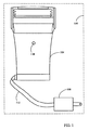
説明は、個人用の体毛除去装置の一具現化例の概略的な模式図である図1を用いてなされる。装置100は、被験者の皮膚上でのスムーズな動作に適用されるアプリケータ104と、充電デバイス108と、アプリケータ104と充電デバイス108とを接続するハーネス112とを備える。ハーネス112は、アプリケータ104と充電デバイス108との間の電気的な伝導を可能とする。装置100は、標準的な電力供給網のコンセントから電力供給を受け取るか、再充電可能又は標準的なバッテリからの電力を受け取る。LED118はアプリケータ104の動作状態を表示する。
The description will be made with reference to FIG. 1 which is a schematic diagram of an embodiment of a personal hair removal device. The
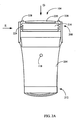
図2は図1の装置のアプリケータの第1の具体例の概略的な模式図である。アプリケータ104(図2A)は、第1の端部208及び第2の端部212を有して、人間工学的に設計された、手にフィットするケーシング204を有する。一つ以上の照明源216、少なくとも一つの体毛除去機構220、及び少なくとも一つは、照明源216及び体毛除去機構220を起動するためのマイクロスイッチ228として示される皮膚感知機構に接触する。マイクロスイッチ228は、第1の端部208に配置され、アプリケータ104を皮膚に適用することによって(図示せず)起こるわずかな圧力によって起動される。押し下げられると、マイクロスイッチ228は一つ以上の照明源216及びアプリケータ104の他の電気及び電子回路を起動する。一具現化例にあって、照明源216及び他の電気及び電子回路は、相互に対して独立的に動作され、例えば、RF電流感知機構のように、固有のオン及びオフスイッチ機構を有する。
FIG. 2 is a schematic diagram of a first example of the applicator of the apparatus of FIG. Applicator 104 (FIG. 2A) has an ergonomically designed hand-
照明源216は、白熱光、キセノン光、レーザダイオード、LED、レーザ又はこれらの組み合わせのようなものである。照明源216は、断続的又は連続的な動作モードにて動作する。照明源216の電力及び動作時間は、皮膚の処置部への潜在的な損傷を避けるために選択される。各照明源216は、アプリケータ104の手にフィットするケージング204のような人間工学的な設計部から取り外せるカートリッジ上のパッケージング224に収納されている。照明源のパッケージング状のカートリッジは、異なる照明源を同一のアプリケータに用いることを許容する。パッケージング224の照明源216の各カートリッジは、スプリング上に取り付けられるか、図2Bにあって矢印240にて示されるアプリケータケーシング204に関して光源216付きのカートリッジ状のパッケージング224の自由な動きを可能とするフレキシブルな取り付けとされる。これは、照明源216付きカートリッジ224に、アプリケータ104が処置される皮膚の部分にわたって動かされるときに、皮膚/ケージングの輪郭244を追随させる。動き方向検出器232は、アプリケータの動き方向を検出し、さらに光源216の適切なスイッチング用の信号を提供する。
The
冷却装備は、アプリケータ104の第2の端部212に配置される部分236に位置されるかもしれない例えばファン(図示せず)である。前記ファンは、電気及び電子回路の動作、さらにはアプリケータの光又はLEDによって発生される熱を除去し、アプリケータの正常な動作状態を可能にする。
The cooling equipment is, for example, a fan (not shown) that may be located in a portion 236 located at the
図2Cは、アプリケータ104の具現化例の第1の端部208の上面部の概略図である。図は、光源216のカートリッジ状のパッケージング224、体毛除去機構220、及びマイクロスイッチ228を示す。
FIG. 2C is a schematic view of the upper surface portion of the
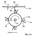
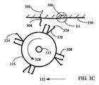
図3Aに示される、一つの具現化例にあって、体毛除去機構220は、軸312の周りを回転するホルダー316に取り付けられる、少なくとも一組の毛抜き308を備える。同じ軸に取り付けられた毛抜き308の近傍は、刃324によって仕切られるレバー320である。代替的に、レバー320は、毛抜き308の後の一定のフォローアップを確実にするために、毛抜き308に堅く結合されてもよい。毛抜き308の位置と皮膚330に関するレバー320の刃324の位置との間には、あらかじめセットされた差異がある。典型的には、刃324は皮膚330に毛抜き308よりも接近している。刃324と毛抜き308の位置における差異は、皮膚、体毛、及び被験者の個人の処置される部分のタイプによって規定される。
In one implementation shown in FIG. 3A, the
体毛304の除去のため、毛抜き308は皮膚330に適用される。ホルダー316は、矢印328で示される方向に回転し、同時に矢印332によって示される方向に皮膚330の表面上を線形に回転しながら移動する。気抜き308は回転を継続するので、毛抜き308は、少なくとも1本の毛幹304(図3B)を持ち上げ、皮膚330から抜き始める。毛抜き308の回転によって生成され、毛幹304に適用されるホルダー316の線形な動きによって支持される引っ張る力は、毛幹304、毛幹及び毛嚢を取り囲む皮膚330を引っ張る。この力は、皮膚330を変形させ、毛嚢を取り囲んでいる皮膚表面の残りを超えて突出する鳥肌340を形成する。刃324は、鳥肌340の頂点に可能な限り接近している体毛304(図3C)を切断する。引っ張り力は、体毛をピンと張るように設定されるが、皮膚から体毛を抜くほどではない。
A
図4は、毛幹又は毛嚢を切断及び収縮させる様子を示す拡大概略図である。毛幹304の切断に続いて、突起340が形成された皮膚330は収縮される。毛幹304の残余部は、毛嚢306の方向のオリジナルの位置に収縮される。毛幹304は、皮膚表面又は皮膚の角質層144よりも深く収縮され、番号404(図4)にて示されるように、体毛の位置にて差が示され、体毛は実質的に皮膚表面の下に存在する。番号408は、組織を示す。
FIG. 4 is an enlarged schematic view showing how the hair shaft or hair follicle is cut and contracted. Following cutting of the
ホルダー316(図3C及び3D)は矢印328で示される方向に回転を続け、さらに矢印332にて示される方向に皮膚330の表面上を線形又は他のタイプの動きにて移動する。毛抜き308は他の毛幹304を掴み、突起340を前述の一具体例と同様の方法にて形成する。次に、毛幹304は、その前の毛幹が切断されたのと同じような方法により切断される。毛抜き308及び刃324は、同じ方向に向けられるか、前後にずらされ、さらに異なる方法に向けられる。毛抜き308及び刃324のいくつかが異なる方向に向けられると、ユーザは以前に処置された皮膚部分及び効果的なとこまで、毛抜き308及び刃324を戻す。毛抜き308及び刃324が同じ方向に向けられると、ユーザは治療ストロークの終わりで、アプリケータを回転し、次の皮膚部分の処置のために、反対方向又は同一の位置にする。
Holder 316 (FIGS. 3C and 3D) continues to rotate in the direction indicated by
代替的に、体毛除去機構220は、例えば、ドイツのBraun GmbHから市販されているモデル3470ソフトパーフェクト(Softperfect)という女性用電気シェーバのような、レザー、シェービング、又は電気シェーバのような周知の機械的な体毛除去機構の任意の一つである。このモデルは、毛をむしりとったり、引き抜く他の取り付け可能なヘッドも備える。類似した、又は同一の機構さえも、もちろん、男性の体毛除去/シェーバに適用可能である。照明ヘッドは、シェーバ又は電動脱毛器又はレーザのいずれか一つのヘッドのみを伴う従来の電動脱毛器に取り付けられて動作される。体毛除去機構は、タスクのために最も適切な機構がアプリケータ上で組み立てられる、交換可能な機構である。
Alternatively, the
複数の照明源216(図2)は、体毛除去機構220と同時に動作する。しかし、複数の照明源は体毛除去機構220が既に除去した体毛の皮膚範囲とは異なる範囲を照明する。照明は、たまに残される毛嚢及び毛根を破壊又は弱体化、機械的な体毛の脱毛に続くべきである。体毛除去機構220の動作への照明源216の同期のため、動き方向センサ、又は複数の光源216の間で切り換わる単なる方向センサ(図示せず)が、アプリケータ104を装備する。方向センサは、例えば、光源を調節するための複数の開口を有する回転する車輪、任意のタイプの機械的なスイッチ、光学的マウス型方向センサ、及び他の異なるタイプである。方向センサによる光源の起動は、アプリケータが最小の速度で皮膚上を移動するときにのみ照明源が動作可能となるので、偶然の皮膚の火傷又は他の治療の副作用を軽減する。さらに、適切な照明源が処置される皮膚部分を照明することがアプリケータの進む方向に基づいて作動するのを確実にすることを可能とする。複数の照明源216は、継続又は断続的な動作モードにあって典型的に動作する。
The plurality of illumination sources 216 (FIG. 2) operate simultaneously with the
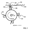
図5は体毛除去機構の第2の具体例の概略的な模式図である。櫛タイプ保護板500は、皮膚330、特に突出部340を回転する刃324(図3)による偶然の損傷から保護する。複数の刃324は、毛抜き308によって引っ張られた体毛306を切断する、固定された刃で置き換えられてもよい。そのような具現化例にあって、ホルダー316は回転に加えて線形の動きをする。代替的に、相互に関して線形に滑走する二つの櫛状の刃は、体毛を切断するために動作される。
FIG. 5 is a schematic diagram of a second specific example of the hair removal mechanism. The comb-
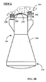
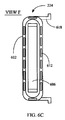
図6はアプリケータの照明カートリッジの具体例の概略的な模式図である。カートリッジ224のプラスチックの筺体602は、白熱光、キセノンフラッシュ光、レーザダイオード、LED、レーザ又はこれらの組み合わせのような照明源を実装する。図6はキセノン光606と、その光によって照射された光輝の大部分を集光し、さらに皮膚の処置部分に向ってその光を方向づけるように構成された反射鏡610とを示す。
FIG. 6 is a schematic diagram of a specific example of the illumination cartridge of the applicator. The
カートリッジ224のプラスチックの筺体602は、カートリッジ224の容易な挿入と、矢印622によって示される方向に沿ってのカートリッジの動きをサポートする二つのガイド618を備える。この開示されたカートリッジの構成は、図2Bに示した、処理される皮膚部分の輪郭244に容易に追従させ、さらに処理される皮膚部分の均一な照射を維持させる。一つの具体例にあって、カートリッジ224の動きは、マイクロスイッチ228の交換に使用される。これは、カートリッジ224に、マイクロスイッチ228の電気的及び電子的回路と同じモードにおいて、アプリケータの電気的及び電子的回路を起動させる。代替的に、ガイド618は、金属化され、さらにはガイド618の下降は電気回路を閉じる。ガイドの一部を透明にし、他の部分を不透明にすることも可能である。そのようなガイドの線形な動きは、光束を変調し、さらにアプリケータ104の電気的及び電子的回路を起動又は不起動する。以下に説明するように、他の検出およびスイッチング機構によるマイクロスイッチの置き換えの付加的な方法が用いられる。
The
反射鏡610は、冷却光606用のフリーな空気の流れを可能にする二つの類似のハーフ部から構成されるように示されている。代替的に、それぞれ空気取り入れ開口608と一体のボディとして形成される反射鏡として用いられてもよい。反射鏡開口608は、光606又は複数のLED(図示せず)の対流性冷却を可能にする空気の通気口又は空気取り入れ開口612のそれぞれと協働する。
The
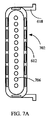
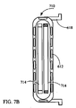
図7は、アプリケータの光源構成の他の具体例の概略的な模式図である。図7Aは、カートリッジ224と同様のカートリッジ702を複数のLED706を伴って示している。各LED706は、単一波長又は複数の波長の光を照射する。複数のLED706は、比較的均一な光束分布を有する光束によって皮膚の処置部を照射するように構成される。図7Bは、キセノン又は他のタイプの光のような二つの光源714付のカートリッジ710を示している。光源714は、同一の光源でも或いは異なる光源でもよい。二つの光源714は、同時か、異なるか又は部分的に重なる期間で、さらには例えば断続的又は継続的な、異なる動作モードで動作される。
FIG. 7 is a schematic diagram of another specific example of the light source configuration of the applicator. FIG. 7A shows a
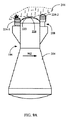
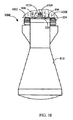
上述されたアプリケータ構成は、体毛除去機構及び照射源の異なる組み合わせをサポートする。つまり、交換可能な体毛除去機構と照射源の特別な構成は、アプリケータの動作モードを決定する。機械的な体毛除去装置の機構は、例えば、回転ベースの毛抜きタイプの電動脱毛器、ばねタイプ電動脱毛器、レザー、又は電動シェーバから、選択される。照明源は、例えば、連続又は断続的な動作源、処置される皮膚部上における所望のスペクトラム及び照射分布を提供する照射源から選択される。これらは、同時に又は部分的に重なる期間にて動作する光源の混合であってもよい。この選択は、異なる処置に適用される事実上無限の組み合わせの多様性を提供する。図8Aに示される一つの他の具現化例にあって、アプリケータ802は、治療される皮膚部に接触し、さらにアプリケータケーシング(図8A)に配置されたRF発生器によって発生される、RFエネルギーを二つの電極806間に位置される皮膚部814(図8B)に提供するように構成される一つ以上のRF電極806を備える。典型的に、アプリケータ802の電気的又は電子的回路は、電力を一つ以上の照明源又はRF源に供給するのを可能にする回路を備える。複数のRF電極806が患者の皮膚(図8B)に触れると、それらのRF電極は、アプリケータ802の電気的及び電子的回路の電流用に経路を提供する。インピーダンス検出機構は、無限の値から測定可能な有限の値までのインピーダンスの変化を検出するとともに、所望の皮膚又は組織に治療効果を提供するのに十分な大きさを有するRFエネルギーの供給を活性化する。RF誘導電流は、参照番号826によって概略的に示される組織ボリュームを加熱する電極806間にて、破線822で示されるように組織818に流れる。このように、RF電極806と皮膚との接触がなければRFはほとんど或いは全く照射されないので、アプリケータの使用は、機械的なスイッチよりも安全である。インピーダンス変化への電気的な反応は、機械的なスイッチングよりも迅速で、さらに一つの電極が皮膚との接触を失うと、RF放射は直ちにスイッチオフされる(全般的に、皮膚との接触が再び確立されれば、照明源及びRFエネルギーを活性化するのを可能とするために非常に低いレベルのRFエネルギーが放射され続けるかもしれない)。任意に、アプリケータ802は、アプリケータ802を完全にスイッチオフするためにオンーオフスイッチを有してもよい。図8Cは、前記アプリケータの第3の具体例の他の概略的な模式図である。この具体例にあって、RF電極806は、カートリッジ224の外側に配置されており、図8DはRF電極806がカートリッジ224の両側に配置されるアプリケータの他の具体例を示す。図8Eは、アプリケータ802のさらに他の具体例、つまりカートリッジ224の両側に配置されるRF電極806付きの一つのカートリッジ224が使用されるところの具体例を示す。
The applicator configuration described above supports different combinations of hair removal mechanisms and irradiation sources. That is, the special configuration of the replaceable hair removal mechanism and the irradiation source determines the operating mode of the applicator. The mechanical hair removal device mechanism is selected from, for example, a rotary-based tweezer-type electric epilator, a spring-type electric epilator, leather, or an electric shaver. The illumination source is selected from, for example, a continuous or intermittent operating source, an illumination source that provides a desired spectrum and illumination distribution on the skin to be treated. These may be a mixture of light sources operating at the same time or partially overlapping periods. This choice provides a virtually unlimited variety of combinations that apply to different treatments. In another alternative embodiment shown in FIG. 8A, the
体毛除去機構、照明部及びそれらの機能性のような前述したアプリケータ104(図2)の全ての部品は、アプリケータ802にも必要な変更を加えて適用可能である。
All the parts of the applicator 104 (FIG. 2) described above, such as the hair removal mechanism, lighting section and their functionality, can also be applied to the
図9は、本発明のアプリケータの第1の具体例を用いた体毛除去処理の概略的な模式図である。アプリケータ104の第1端部228は皮膚244に当てられる。これはマイクロスイッチ228上にわずかな圧力をもたらし、それゆえ体毛除去機構220及び適切な照明源が動作可能とされる(一般的に、体毛除去機構及び照明源の両方は、マイクロスイッチ機構からは独立された他の機構によって動作可能とされる)。アプリケータの使用者は、皮膚244の一部から他の皮膚部への矢印902(図9A)によって示される第1方向におけるスキャニング動作で、アプリケータ104を移動する。前記移動の間、体毛除去機構220は、皮膚244の処置される部分から体毛を除去する。移動方向検出器は動作方向を検出し、さらに体毛が除去される皮膚部分を照射するためにカートリッジ224−1ないに配置される照明源の追跡を起動する。照明源224−1を追跡することによって生成される連続的な照明光束は早期に機械的に除去されるように試みられた皮膚部分を加熱し、毛嚢及び毛根を衰弱させ、さらには多分破壊する。照明光束の一般的な有効な値は、0.5J/cm2から20J/cm2の範囲内である。毛嚢及び毛根の破壊に加えて、照明光束は皮膚治療の効果を早める。
FIG. 9 is a schematic diagram of body hair removal processing using the first specific example of the applicator of the present invention. The
アプリケータ104が矢印906(図6B)によって示される第2の方向に動くと、体毛除去機構220は同じようなやりかたで機能し、さらに機械的に処置される皮膚部分から体毛を除去する。動き方向検出器は方向移動の変化を検出し、先導照明源から体毛が除去される皮膚部分を照射するカートリッジ224−2に配置される追跡照明源になったカートリッジ224−1に配置される照明源をスイッチオフする。照明源はカートリッジ224−1及び224−2に配置される照明源は、体毛除去機構220と同時に(共に)動作してもよい。しかし、カートリッジ224−1及び224−2に配置される照明源は、体毛除去機構220が動作するよりも、皮膚244の異なる部分にて動作する。複数の照明源は、連続モードで動作されると、それらの電力を所望の皮膚効果をもたらすように設定し、さらに皮膚火傷を防ぐ。任意の温度検出器は、皮膚温度を継続的に測定し、したがって、RF+光源を作動しないように調整する。
When the
前述したように、カートリッジ224−1に配置された追跡照明源によって生成された照明光束は、体毛成長を止める前述した効果を、皮膚治癒効果と同様にもたらす。この効果は、照明光の波長及び強度の適切な選択によりさらに高めることができる。 As described above, the illumination light beam generated by the tracking illumination source disposed on the cartridge 224-1 provides the above-described effect of stopping body hair growth as well as the skin healing effect. This effect can be further enhanced by appropriate selection of the wavelength and intensity of the illumination light.
照明光源の追跡及び案内は典型的に、所望の効果を得るための最も適切な異なる光束の値を発生するために動作する。照明光源が図7Aにて示されたようなLEDベースの光源であると、照明光源の追跡及び案内は所望の効果を得るためのより適切な異なる波長を発するために動作する。一般的に、前述のように照明源カートリッジは、所望の処置効果を得るのに最も適切であるように、異なる電力で照明光を動作するため、または異なるスペクトラムを得るために一つ以上の光を備えるように構成される。 Illumination source tracking and guidance typically operates to generate the most appropriate different luminous flux values to achieve the desired effect. If the illumination source is an LED-based light source as shown in FIG. 7A, the illumination source tracking and guidance operates to emit different wavelengths that are more appropriate to achieve the desired effect. In general, as described above, the illumination source cartridge operates with more than one light to operate illumination light at different powers or to obtain different spectra, as is most appropriate to obtain the desired treatment effect. It is comprised so that it may comprise.
図10は本発明の他の具現化例を用いての体毛除去処理の概略的な模式図である。アプリケータ1000は、RF電極806及び皮膚1002の間の接触を形成するように、皮膚1002に当てられる。インピーダンス検出機構は、任意からある値までのインピーダンスの変化を検出し、さらにアプリケータ100の電気的及び電子的回路を起動する。このため、インピーダンス検出機構は、両方の機構を安全な処理を提供するために組み合わせることができるけれども、前述したマイクロスイッチ機構に置き換えることができる。機械的な体毛除去機構は、物理的に体毛を除去する。破線1022で示されるRF誘導電流は組織1006及び特にはボリューム1026を加熱し、残っている毛嚢及び毛根を弱らせ或いは破壊する。前記アプリケータの使用者は、アプリケータ1000を皮膚1002の一部から他の皮膚部にスキャンモーションにて移動し、それぞれの組織ボリューム1026を加熱する。前記移動のコースにあって、体毛除去機構220は加熱された組織ボリュームを覆って配置される皮膚1002部分から体毛を除去する。動き方向検出器232(図2A)は、動き方向を検出し、体毛が除去される皮膚部分を照射するために照明光源224の追跡動作を起動する。照明光源224を追跡することによって生成される照明光束は、毛嚢及び毛幹を弱らせ、さらにはある程度まで、皮膚を加熱し、残っている毛嚢及び毛根を機械的な手段によって動かされることなく、破壊する。毛嚢及び毛根の破壊に加えて、照明光束は皮膚治癒効果を促進する。前述の照明光束及び波長のバリエーション及び照明光源のスイッチングはRFをより深い組織層を加熱するために用いるところの本発明の具体例に適用することができるように変更される。
FIG. 10 is a schematic diagram of body hair removal processing using another embodiment of the present invention.
皮膚処置結果は、処置される皮膚部分の適切な準備によって向上されるかもしれない。処置後の発疹は、クリーム及びローションを適用によって削減できるであろう。図11は、本発明のアプリケータの第4の具体例の概略的な模式図である。アプリケータ1100は、前述した体毛除去機構228、照明源224、RF電極806、およびマイクロスイッチ228に加えて、皮膚および体毛の事前処置デバイス1104及び皮膚及び体毛の事後処置デバイスを供える。皮膚及び体毛の事前処置デバイス1104は、処置される皮膚部分を噴霧剤又は同様の液剤によって清潔にするように動作される。皮膚及び体毛の事後処置デバイス1108は、処置された皮膚部分に亘って、処置が時々皮膚に引き起こすかもしれない炎症を低減するクリーム又は液剤を分散するように動作される。任意の可変長スペーサ1112は、体毛除去機構の配置場所と皮膚との間の所望のギャップを維持するために用いられる。
Skin treatment results may be improved by appropriate preparation of the skin portion to be treated. The rash after treatment could be reduced by applying creams and lotions. FIG. 11 is a schematic diagram of a fourth example of the applicator of the present invention. The
典型的に、前述のアプリケータの任意の一つは、電気的に駆動される。すなわち、体毛除去機構を回転するため、及びアプリケータの他のユニットを動作するためのドライブによって、駆動される。代替的に、アプリケータは、患者の皮膚にわたる滑らかな動きが体毛除去機構への回転動作を提供するように構成される。 Typically, any one of the aforementioned applicators is electrically driven. That is, it is driven by a drive for rotating the hair removal mechanism and for operating other units of the applicator. Alternatively, the applicator is configured such that a smooth movement across the patient's skin provides a rotational movement to the hair removal mechanism.
前記方法のアプリケータは、体毛のフリーな皮膚領域でも機械的な体毛除去のために実現されるのを可能にし、さらに、RFの適用及び皮膚への照射によって体毛の再成長の遅延又は完全な削除が可能となる(同時、又は後続、又は機械的な体毛除去に優先する)。皮膚の治癒処理は、適切な皮膚照射光波長の選択によって促進される。 The applicator of the method allows realization of mechanical hair removal even in free skin areas of the body hair, and further delays or completes hair regrowth by applying RF and irradiating the skin. Deletion is possible (prior to simultaneous or subsequent or mechanical hair removal). The skin healing process is facilitated by selection of an appropriate skin irradiation light wavelength.
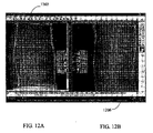
図12は、本発明によって処置される患者の皮膚の一部の写真画像及び患者の皮膚の非処置部分(制御)の画像である。処置された部分1206は、残余の体毛さえも含んでいない。非処置部分1202は、比較の目的のために示されている。
FIG. 12 is a photographic image of a portion of a patient's skin to be treated according to the present invention and an image of a non-treated portion (control) of the patient's skin. Treated
多くの具現化例を説明した。それにもかかわらず、本発明の方法の思想及び範囲からそれることなく、様々な変更がなされることが理解されるでしょう。つまり、他の具現化例は、以下の請求項の範囲内にある。 A number of implementation examples have been described. Nevertheless, it will be understood that various modifications can be made without departing from the spirit and scope of the method of the present invention. That is, other implementations are within the scope of the following claims.
Claims (28)
機械的に交換可能な体毛除去機構と、
アプリケータが患者の皮膚上に当てられさらに皮膚上で動かされるとアプリケータの移動方向に応じて少なくとも一つの照明光源を起動するために構成される方向検出器である複数の検出器の少なくとも一つを伴う、一つ以上の検出器と、
を備える体毛除去用のアプリケータ。 One or more illumination light sources configured to provide illumination light of one or more wavelengths;
A mechanically replaceable hair removal mechanism;
At least one of the plurality of detectors being a direction detector configured to activate at least one illumination source in response to the direction of movement of the applicator when the applicator is applied to the patient's skin and further moved on the skin. One or more detectors with one,
An applicator for removing hair.
体毛が除去されなければならない皮膚部に、RF及び適切な照明のような皮膚加熱機構によって生成される熱を適用することと、
前記皮膚の前記ターゲット部上に伸びる体毛を機械的な手段によって除去すること
とを備える皮膚から体毛を除去するための方法。 Moving an applicator having at least a hair removal and skin heating mechanism across the target portion of the skin in a scanning motion;
Applying heat generated by a skin heating mechanism, such as RF and appropriate lighting, to the skin where hair must be removed;
Removing the body hair extending on the target portion of the skin by mechanical means.
前記方法は、処置される皮膚部分に適用されて前記皮膚にRF放射を行うRF電極の間の有限インピーダンスの存在、少なくとも一つの照明源による処置される皮膚部分、及び処置後のクリームの適用を特徴とする方法。 Applying to the skin a mechanical hair removal mechanism, at least one RF electrode configured to heat the skin, and at least one illumination source configured to illuminate the skin portion to be treated. A method for safely removing hair from skin, comprising:
The method comprises the presence of a finite impedance between RF electrodes that are applied to the treated skin portion to emit RF radiation to the skin, the treated skin portion with at least one illumination source, and the application of the cream after treatment. Feature method.
前記体毛が機械的に除去された前記皮膚部分は適切な波長及び電力による照明光によって照射され、皮膚の発疹を低減するクリーム又はローションは同一の皮膚部分にわたって塗られることを特徴とする方法。 A skin healing method after promoting hair removal,
The method wherein the skin portion from which the body hair has been mechanically removed is irradiated with illumination light of an appropriate wavelength and power, and a cream or lotion that reduces skin rashes is applied over the same skin portion.
前記方法は前記アプリケータが静止であるか又は変位速度が目標値よりも遅い時には、前記動き方向センサが照明光源をスイッチオフすることを特徴とする方法。 A safe method for treatment with illuminating light comprising applying an applicator having at least one illumination source and a motion direction detector to the skin,
The method is characterized in that the motion direction sensor switches off the illumination light source when the applicator is stationary or the displacement rate is slower than a target value.
前記方法は動き方向検出器が前記アプリケータの進む方向に関係して適切な照明源を起動することを特徴とする方法。 A safe method for skin treatment illumination, wherein an applicator having at least one illumination source and a motion direction detector is applied to the skin,
The method is characterized in that the motion direction detector activates an appropriate illumination source in relation to the direction of travel of the applicator.
一つ以上の波長を照明光に与えるように構成される一つ以上の照明源と、
交換可能な機械的な体毛除去機構と、
前記アプリケータが患者の皮膚に当てられ皮膚にわたって変移されると少なくとも一つの照明源を起動するための構成される動き検出器である検出器の少なくとも一つを伴う、一つ以上の検出器と
を備える体毛除去用のアプリケータ。 An applicator for removing hair,
One or more illumination sources configured to provide illumination light with one or more wavelengths;
Replaceable mechanical hair removal mechanism,
One or more detectors with at least one detector that is a motion detector configured to activate at least one illumination source when the applicator is applied to and displaced across the patient's skin; An applicator for removing hair.
Applications Claiming Priority (2)
| Application Number | Priority Date | Filing Date | Title |
|---|---|---|---|
| US2172308P | 2008-01-17 | 2008-01-17 | |
| PCT/IL2009/000033 WO2009090632A2 (en) | 2008-01-17 | 2009-01-08 | A hair removal apparatus for personal use and the method of using same |
Related Child Applications (1)
| Application Number | Title | Priority Date | Filing Date |
|---|---|---|---|
| JP2013223330A Division JP5701960B2 (en) | 2008-01-17 | 2013-10-28 | Hair removal device for personal use and method of use thereof |
Publications (2)
| Publication Number | Publication Date |
|---|---|
| JP2011509732A true JP2011509732A (en) | 2011-03-31 |
| JP2011509732A5 JP2011509732A5 (en) | 2013-08-01 |
Family
ID=43952850
Family Applications (2)
| Application Number | Title | Priority Date | Filing Date |
|---|---|---|---|
| JP2010542736A Pending JP2011509732A (en) | 2008-01-17 | 2009-01-08 | Hair removal device for personal use and method of use thereof |
| JP2013223330A Expired - Fee Related JP5701960B2 (en) | 2008-01-17 | 2013-10-28 | Hair removal device for personal use and method of use thereof |
Family Applications After (1)
| Application Number | Title | Priority Date | Filing Date |
|---|---|---|---|
| JP2013223330A Expired - Fee Related JP5701960B2 (en) | 2008-01-17 | 2013-10-28 | Hair removal device for personal use and method of use thereof |
Country Status (1)
| Country | Link |
|---|---|
| JP (2) | JP2011509732A (en) |
Cited By (4)
| Publication number | Priority date | Publication date | Assignee | Title |
|---|---|---|---|---|
| JP2013180211A (en) * | 2012-03-03 | 2013-09-12 | Smart Gold Development Ltd | Electric heating depilator |
| JP2013236901A (en) * | 2012-05-11 | 2013-11-28 | Psi Co Ltd | Depilatory control device |
| JP2014516751A (en) * | 2011-06-22 | 2014-07-17 | ラディアンシー インク. | Hair loss and hair growth inhibiting device |
| CN110785102A (en) * | 2017-06-23 | 2020-02-11 | 博朗有限公司 | Depilator |
Citations (8)
| Publication number | Priority date | Publication date | Assignee | Title |
|---|---|---|---|---|
| FR2424109B1 (en) * | 1978-04-27 | 1982-12-10 | Philips Nv | |
| JPH11513929A (en) * | 1996-08-16 | 1999-11-30 | フィリップス エレクトロニクス ネムローゼ フェンノートシャップ | Hair removal device with adjustable hair pull-out distance |
| JP2000060629A (en) * | 1998-08-26 | 2000-02-29 | Matsushita Electric Works Ltd | Hair remover |
| JP2001029124A (en) * | 1999-07-19 | 2001-02-06 | Ya Man Ltd | Laser depilation probe |
| JP2003290573A (en) * | 2002-03-29 | 2003-10-14 | Matsushita Electric Works Ltd | Hair treating instrument |
| JP2004509694A (en) * | 2000-09-28 | 2004-04-02 | シネロン・メデイカル・リミテツド | Apparatus and method for treating skin |
| JP2004159666A (en) * | 1999-12-21 | 2004-06-10 | Ya Man Ltd | Laser epilation device |
| JP2006501911A (en) * | 2002-10-05 | 2006-01-19 | ブラウン、ゲゼルシャフト、ミット、ベシュレンクテル、ハフツング | Hair removal equipment |
Family Cites Families (3)
| Publication number | Priority date | Publication date | Assignee | Title |
|---|---|---|---|---|
| JP3340092B2 (en) * | 1999-07-29 | 2002-10-28 | ヤーマン株式会社 | Laser hair removal probe |
| US20070213698A1 (en) * | 2006-03-10 | 2007-09-13 | Palomar Medical Technologies, Inc. | Photocosmetic device |
| JP2004148107A (en) * | 2002-10-11 | 2004-05-27 | Vine:Kk | Lustrous skin device and treatment device |
-
2009
- 2009-01-08 JP JP2010542736A patent/JP2011509732A/en active Pending
-
2013
- 2013-10-28 JP JP2013223330A patent/JP5701960B2/en not_active Expired - Fee Related
Patent Citations (8)
| Publication number | Priority date | Publication date | Assignee | Title |
|---|---|---|---|---|
| FR2424109B1 (en) * | 1978-04-27 | 1982-12-10 | Philips Nv | |
| JPH11513929A (en) * | 1996-08-16 | 1999-11-30 | フィリップス エレクトロニクス ネムローゼ フェンノートシャップ | Hair removal device with adjustable hair pull-out distance |
| JP2000060629A (en) * | 1998-08-26 | 2000-02-29 | Matsushita Electric Works Ltd | Hair remover |
| JP2001029124A (en) * | 1999-07-19 | 2001-02-06 | Ya Man Ltd | Laser depilation probe |
| JP2004159666A (en) * | 1999-12-21 | 2004-06-10 | Ya Man Ltd | Laser epilation device |
| JP2004509694A (en) * | 2000-09-28 | 2004-04-02 | シネロン・メデイカル・リミテツド | Apparatus and method for treating skin |
| JP2003290573A (en) * | 2002-03-29 | 2003-10-14 | Matsushita Electric Works Ltd | Hair treating instrument |
| JP2006501911A (en) * | 2002-10-05 | 2006-01-19 | ブラウン、ゲゼルシャフト、ミット、ベシュレンクテル、ハフツング | Hair removal equipment |
Cited By (4)
| Publication number | Priority date | Publication date | Assignee | Title |
|---|---|---|---|---|
| JP2014516751A (en) * | 2011-06-22 | 2014-07-17 | ラディアンシー インク. | Hair loss and hair growth inhibiting device |
| JP2013180211A (en) * | 2012-03-03 | 2013-09-12 | Smart Gold Development Ltd | Electric heating depilator |
| JP2013236901A (en) * | 2012-05-11 | 2013-11-28 | Psi Co Ltd | Depilatory control device |
| CN110785102A (en) * | 2017-06-23 | 2020-02-11 | 博朗有限公司 | Depilator |
Also Published As
| Publication number | Publication date |
|---|---|
| JP2014050739A (en) | 2014-03-20 |
| JP5701960B2 (en) | 2015-04-15 |
Similar Documents
| Publication | Publication Date | Title |
|---|---|---|
| EP2561819B1 (en) | Hair removal apparatus for personal use | |
| US9271793B2 (en) | Method and apparatus for personal skin treatment | |
| JP5701895B2 (en) | Method and apparatus for personal skin treatment | |
| JP5116488B2 (en) | Skin treatment device | |
| KR20140051261A (en) | Hair removal and re-growth suppression apparatus | |
| EP1139898A2 (en) | Energy application with cooling | |
| JP5701960B2 (en) | Hair removal device for personal use and method of use thereof | |
| JP5520955B2 (en) | Method and apparatus for personal skin treatment | |
| JP2011509732A5 (en) | ||
| CN219070620U (en) | Processing device for performing light-based processing operations | |
| CN116999156A (en) | Processing device for performing light-based processing operations | |
| IL206351A (en) | Hair removal apparatus for personal use and method of using same | |
| ES1073286U (en) | A hair removal apparatus for personal use and the method of using same | |
| AU2012201387B2 (en) | A method and apparatus for personal skin treatment |
Legal Events
| Date | Code | Title | Description |
|---|---|---|---|
| A621 | Written request for application examination |
Free format text: JAPANESE INTERMEDIATE CODE: A621 Effective date: 20111017 |
|
| A977 | Report on retrieval |
Free format text: JAPANESE INTERMEDIATE CODE: A971007 Effective date: 20130426 |
|
| A131 | Notification of reasons for refusal |
Free format text: JAPANESE INTERMEDIATE CODE: A131 Effective date: 20130507 |
|
| A524 | Written submission of copy of amendment under article 19 pct |
Free format text: JAPANESE INTERMEDIATE CODE: A524 Effective date: 20130614 |
|
| A02 | Decision of refusal |
Free format text: JAPANESE INTERMEDIATE CODE: A02 Effective date: 20130716 |