JP2011503968A - A scalable video coding method for fast channel switching and increased error resilience - Google Patents
A scalable video coding method for fast channel switching and increased error resilience Download PDFInfo
- Publication number
- JP2011503968A JP2011503968A JP2010532055A JP2010532055A JP2011503968A JP 2011503968 A JP2011503968 A JP 2011503968A JP 2010532055 A JP2010532055 A JP 2010532055A JP 2010532055 A JP2010532055 A JP 2010532055A JP 2011503968 A JP2011503968 A JP 2011503968A
- Authority
- JP
- Japan
- Prior art keywords
- scalable
- layer
- video
- random access
- access points
- Prior art date
- Legal status (The legal status is an assumption and is not a legal conclusion. Google has not performed a legal analysis and makes no representation as to the accuracy of the status listed.)
- Withdrawn
Links
Images


Classifications
-
- H—ELECTRICITY
- H04—ELECTRIC COMMUNICATION TECHNIQUE
- H04N—PICTORIAL COMMUNICATION, e.g. TELEVISION
- H04N21/00—Selective content distribution, e.g. interactive television or video on demand [VOD]
- H04N21/40—Client devices specifically adapted for the reception of or interaction with content, e.g. set-top-box [STB]; Operations thereof
- H04N21/43—Processing of content or additional data, e.g. demultiplexing additional data from a digital video stream; Elementary client operations, e.g. monitoring of home network or synchronising decoder's clock; Client middleware
- H04N21/438—Interfacing the downstream path of the transmission network originating from a server, e.g. retrieving MPEG packets from an IP network
- H04N21/4383—Accessing a communication channel
-
- H—ELECTRICITY
- H04—ELECTRIC COMMUNICATION TECHNIQUE
- H04N—PICTORIAL COMMUNICATION, e.g. TELEVISION
- H04N19/00—Methods or arrangements for coding, decoding, compressing or decompressing digital video signals
- H04N19/30—Methods or arrangements for coding, decoding, compressing or decompressing digital video signals using hierarchical techniques, e.g. scalability
- H04N19/33—Methods or arrangements for coding, decoding, compressing or decompressing digital video signals using hierarchical techniques, e.g. scalability in the spatial domain
-
- H—ELECTRICITY
- H04—ELECTRIC COMMUNICATION TECHNIQUE
- H04N—PICTORIAL COMMUNICATION, e.g. TELEVISION
- H04N19/00—Methods or arrangements for coding, decoding, compressing or decompressing digital video signals
- H04N19/65—Methods or arrangements for coding, decoding, compressing or decompressing digital video signals using error resilience
- H04N19/68—Methods or arrangements for coding, decoding, compressing or decompressing digital video signals using error resilience involving the insertion of resynchronisation markers into the bitstream
-
- H—ELECTRICITY
- H04—ELECTRIC COMMUNICATION TECHNIQUE
- H04N—PICTORIAL COMMUNICATION, e.g. TELEVISION
- H04N19/00—Methods or arrangements for coding, decoding, compressing or decompressing digital video signals
- H04N19/85—Methods or arrangements for coding, decoding, compressing or decompressing digital video signals using pre-processing or post-processing specially adapted for video compression
- H04N19/89—Methods or arrangements for coding, decoding, compressing or decompressing digital video signals using pre-processing or post-processing specially adapted for video compression involving methods or arrangements for detection of transmission errors at the decoder
-
- H—ELECTRICITY
- H04—ELECTRIC COMMUNICATION TECHNIQUE
- H04N—PICTORIAL COMMUNICATION, e.g. TELEVISION
- H04N21/00—Selective content distribution, e.g. interactive television or video on demand [VOD]
- H04N21/20—Servers specifically adapted for the distribution of content, e.g. VOD servers; Operations thereof
- H04N21/23—Processing of content or additional data; Elementary server operations; Server middleware
- H04N21/236—Assembling of a multiplex stream, e.g. transport stream, by combining a video stream with other content or additional data, e.g. inserting a URL [Uniform Resource Locator] into a video stream, multiplexing software data into a video stream; Remultiplexing of multiplex streams; Insertion of stuffing bits into the multiplex stream, e.g. to obtain a constant bit-rate; Assembling of a packetised elementary stream
- H04N21/2362—Generation or processing of Service Information [SI]
Landscapes
- Engineering & Computer Science (AREA)
- Multimedia (AREA)
- Signal Processing (AREA)
- Compression Or Coding Systems Of Tv Signals (AREA)
Abstract
本発明の装置は、ベースレイヤビデオ符号化信号とエンハンスメントレイヤのビデオ符号化信号とを有するスケーラブルビデオ符号化(SVC)信号を供給するため、ビデオ信号をエンコードし、ベースレイヤビデオ符号化信号は、エンハンスメントレイヤビデオ符号化信号よりも多くのランダムアクセスポイントを有する。The apparatus of the present invention encodes a video signal to provide a scalable video coding (SVC) signal having a base layer video encoded signal and an enhancement layer video encoded signal, the base layer video encoded signal being It has more random access points than the enhancement layer video encoded signal.
Description
本発明は、たとえば地上波放送、セルラー方式、ワイヤレスフィデリティ(Wi−Fi)、サテライト等のような有線及び無線システムといった通信システムに関する。
本出願は、2007年11月5日に提出された米国仮出願第61/001822号の利益を特許請求するものである。
The present invention relates to communication systems such as wired and wireless systems such as terrestrial broadcasting, cellular systems, wireless fidelity (Wi-Fi), satellites, and the like.
This application claims the benefit of US Provisional Application No. 61/001822, filed Nov. 5, 2007.
圧縮されたビデオビットストリームがワイヤレスネットワークのようなエラーを起こしやすい通信チャネルを通して伝送されるとき、ビットストリームの所定の部分は、破壊されるか又は失われる場合がある。係る誤りのあるビットストリームが受信機に到達し、ビデオデコーダによりデコードされるとき、再生の品質はひどく影響される可能性がある。ソースの誤り耐性の符号化は、この問題に対処するために使用される技術である。 When a compressed video bitstream is transmitted over an error-prone communication channel such as a wireless network, certain portions of the bitstream may be destroyed or lost. When such an erroneous bit stream reaches the receiver and is decoded by the video decoder, the quality of the reproduction can be severely affected. Source error resilience coding is a technique used to address this problem.
ビデオブロードキャスト/マルチキャストシステムでは、ある圧縮されたビデオビットストリームは、セッションと呼ばれる指定された期間で同時にユーザのグループに伝送される。ビデオ符号化の予測の性質のため、あるビットストリームへのランダムなアクセスは、ビットストリーム内の所定のランダムアクセスポイントでのみ利用可能であり、これにより、正しい復号化は、これらランダムアクセスポイントから開始してのみ可能である。ランダムアクセスポイントは低い圧縮効率を一般に有するので、あるビットストリーム内には制限された数の係るポイントのみが存在する。結果として、あるユーザが彼の受信機をあるチャネルに同調してセッションに参加するとき、彼は、正しい復号化を開始させるため、受信されたビットストリームにおける次の利用可能なランダムアクセスポイントを待つ必要があり、これは、ビデオコンテンツの再生において遅延を生じさせる。係る遅延は、チューンイン遅延と呼ばれ、システムのユーザの経験に影響を及ぼす重要な要素である。 In a video broadcast / multicast system, a compressed video bitstream is transmitted to a group of users simultaneously for a specified period called a session. Due to the predictive nature of video coding, random access to certain bitstreams is only available at certain random access points in the bitstream, so that correct decoding starts from these random access points Only possible. Since random access points generally have low compression efficiency, there are only a limited number of such points in a bitstream. As a result, when a user joins a session with his receiver tuned to a channel, he waits for the next available random access point in the received bitstream to start the correct decoding There is a need, which causes a delay in the playback of the video content. Such a delay is called a tune-in delay and is an important factor that affects the experience of the user of the system.
ビデオデリバリシステムでは、幾つかの圧縮されたビデオビットストリームは、共通の伝送媒体を共有するエンドユーザに伝送され、この場合、それぞれのビデオビットストリームは、あるプログラムチャネルに対応する。前のケースと同様に、あるユーザがあるチャネルから別のチャネルに切り替えるとき、彼は、復号化を正しく開始するため、そのチャネルから受信されたビットストリームにおける次の利用可能なランダムアクセスポイントを待つ必要がある。係る遅延は、チャネル切り替え遅延と呼ばれ、係るシステムにおけるユーザの経験に影響を及ぼす別の重要なファクタである。 In a video delivery system, several compressed video bitstreams are transmitted to end users that share a common transmission medium, where each video bitstream corresponds to a program channel. As in the previous case, when a user switches from one channel to another, he waits for the next available random access point in the bitstream received from that channel to start decoding correctly. There is a need. Such delay is referred to as channel switching delay and is another important factor that affects the user experience in such systems.
挿入されたランダムアクセスポイントの利点は、ビデオ符号化の観点から圧縮されたビデオビットストリームの誤り耐性を改善することである。たとえば、あるビットストリームに挿入されるランダムアクセスポイントは、デコーダを周期的にリセットし、誤りの伝播を完全に停止し、これにより、エラーに対するビットストリームのロバスト性が改善される。 The advantage of the inserted random access point is that it improves the error resilience of the compressed video bitstream in terms of video coding. For example, a random access point inserted into a bit stream periodically resets the decoder and stops error propagation completely, thereby improving the robustness of the bit stream against errors.
たとえば、H.264/AVCビデオ圧縮標準(たとえばITU-T Recommendation H.264:“Advanced video coding for generic audiovisual services”, ISO/IEC 14496-10(2005):“Information Technology−Coding of audio-visual objects Part 10: Advanced Video Coding”を参照されたい)を考慮して、ランダムアクセスポイント(スイッチングイネーブリングポイントとも呼ばれる)は、IDR(Instantaneous Decoder Reflesh)スライス、イントラ符号化マクロブロック(MB)及びSI(switching I)スライスを含む符号化方法により実現される。 For example, H.M. H.264 / AVC video compression standard (for example, ITU-T Recommendation H.264: “Advanced video coding for generic audiovisual services”, ISO / IEC 14496-10 (2005): “Information Technology-Coding of audio-visual objects Part 10: Advanced In consideration of "Video Coding", random access points (also called switching enabling points) include IDR (Instantaneous Decoder Reflesh) slices, intra-coded macroblocks (MB) and SI (switching I) slices. This is realized by an encoding method.
IDRスライスに関して、IDRスライスは、正しい復号化のために前のスライスに依存しないイントラ符号化MBのみを含む。IDRスライスは、デコーダでデコーディングピクチャバッファをリセットし、これにより、後続のスライスの復号化は、IDRスライスの前のスライスとは独立である。正しい復号化はIDRスライスの直後に利用可能であるので、瞬間的なランダムアクセスポイントとも呼ばれる。一方で、イントラ符号化MBに基づいて段階的なランダムアクセスが実現される。多数の連続する予測ピクチャについて、イントラ符号化MBは組織的に符号化され、これにより、これらのピクチャを符号化した後、後続するピクチャにおけるそれぞれのMBは、ピクチャのうちの1つにおいて、イントラ符号化され、共同で設置される対応物を有する。したがって、ピクチャの復号化は、ピクチャのセットの前の他のスライスに依存しない。同様に、SIスライスは、このタイプの特別に符号化されたスライスをビットストリームに埋め込むことにより、異なるビットストリーム間の切り替えを可能にする。残念なことに、H.264/AVCでは、IDRスライス又はSIスライスの共通の問題点は、符号化効率のロスである。一般に、かなりの量のビットレートオーバヘッドがスイッチングポイントを埋め込むために支払われる必要がある。 With respect to IDR slices, IDR slices contain only intra-coded MBs that do not depend on previous slices for correct decoding. The IDR slice resets the decoding picture buffer at the decoder so that decoding of subsequent slices is independent of the previous slice of IDR slices. Since correct decoding is available immediately after the IDR slice, it is also called an instantaneous random access point. On the other hand, stepwise random access is realized based on the intra-coded MB. For a number of consecutive predicted pictures, intra-coded MBs are systematically coded, so that after coding these pictures, each MB in subsequent pictures is intra-coded in one of the pictures. Encoded and has a co-located counterpart. Thus, picture decoding does not depend on other slices before the set of pictures. Similarly, SI slices allow switching between different bitstreams by embedding specially encoded slices of this type in the bitstream. Unfortunately, H.C. In H.264 / AVC, a common problem with IDR slices or SI slices is loss of coding efficiency. In general, a significant amount of bit rate overhead needs to be paid to embed switching points.
同様に、スケーラブルビデオ符号化(SVC)においてランダムアクセスポイントが使用される。SVCにおいて、依存の表現は、多数のレイヤ表現から構成される場合があり、アクセスユニットは、1つのフレーム番号に対応する全ての依存性の表現から構成される(たとえばY-K.Wang,M.Hannuksela,S.Pateux,A.Eleftheraidis及びS.Wenger,“System and transport interface of SVC”,IEEE Trans. Circuits and Systems for Video Technology,vol.17,no.9,Sept2007,pp.1149-1163; 並びに、H.Schwarz,D.Marpe及びT.Wiegand,“Overview of the scalable video coding extension of the H.264/AVC standard”,IEEE Trans. Circuits and Systems for Video Technology,vol.17,no.9,Sept2007,pp.1103-1120を参照されたい)。 Similarly, random access points are used in scalable video coding (SVC). In SVC, the dependency representation may be composed of multiple layer representations, and the access unit is composed of all dependency representations corresponding to one frame number (for example, YK.Wang, M.Hannuksela). , S.Pateux, A.Eleftheraidis and S.Wenger, “System and transport interface of SVC”, IEEE Trans. Circuits and Systems for Video Technology, vol. 17, no. 9, Sept 2007, pp. 1149-1163; and H. Schwarz, D. Marpe and T. Wiegand, “Overview of the scalable video coding extension of the H.264 / AVC standard”, IEEE Trans. Circuits and Systems for Video Technology, vol. 17, no. 9, Sept 2007, pp.1103-1120).
ランダムアクセスポイントを埋め込むためのSVCの一般的な方法は、IDRスライスを使用してアクセスユニットを完全に符号化することである。図1に例が示される。図1のSVC符号化信号は、2つの依存性の表現を有しており、それぞれの依存性の表現は、1つのレイヤ表現を有する。特に、ベースレイヤは、D=0と関連されており、エンハンスメントレイヤは、D=1と関連される(“D”の値は、当該技術分野において“dependency_id”とも呼ばれる)。図1は、SVC信号のフレームにおいて生じる9つのアクセスユニットを例示する。破線のボックス10により例示されるように、アクセスユニット1は、第一のレイヤのIDRスライス(D=1)及びベースレイヤのIDRスライス(D=0)を有する。後続のアクセスユニットは、2つの予測された(P)スライスを有する。アクセスユニット1,5及び9のみがIDRスライスを有することが図1から観察される。係るように、ランダムアクセスは、これらのアクセスポイントで行われる。しかし、H.264/AVCの場合のように、IDRスライスで符号化されたそれぞれのアクセスユニットは、SVCの符号化効率を減少させる。
A common SVC method for embedding random access points is to fully encode the access unit using IDR slices. An example is shown in FIG. The SVC encoded signal of FIG. 1 has two dependency representations, and each dependency representation has one layer representation. In particular, the base layer is associated with D = 0 and the enhancement layer is associated with D = 1 (the value of “D” is also referred to in the art as “dependency_id”). FIG. 1 illustrates nine access units that occur in a frame of an SVC signal. As illustrated by the
本発明の原理によれば、ビデオ信号を送信する方法は、複数のスケーラブルレイヤを含むビデオ符号化信号を供給するために信号にスケーラブルビデオ符号化を施すステップを含み、スケーラブルレイヤのうちの1つは、他のスケーラブルレイヤよりも多くのランダムアクセスポイントを有するように選択される。また、本方法は、スケーラブルビデオ符号化された信号を送信するステップを含む。結果として、ビデオエンコーダは、圧縮されたビデオビットストリームに更なるスイッチングイネーブルポイントを埋め込むことで、受信機におけるチューンイン遅延及びチャネル切り替え遅延を低減することができる。 In accordance with the principles of the present invention, a method for transmitting a video signal includes applying scalable video coding to a signal to provide a video encoded signal that includes a plurality of scalable layers, wherein one of the scalable layers is provided. Is selected to have more random access points than other scalable layers. The method also includes transmitting a scalable video encoded signal. As a result, the video encoder can reduce tune-in delay and channel switch delay at the receiver by embedding additional switching enable points in the compressed video bitstream.
本発明の例示的な実施の形態では、SVC信号は、ベースレイヤ及びエンハンスメントレイヤを有し、ベースレイヤは、エンハンスメントレイヤよりも多くのランダムアクセスポイントを有するように選択される。
上述された観点で、詳細な説明を読むことから明らかであるように、他の実施の形態及び特徴も可能であり、本発明の原理に含まれる。
In an exemplary embodiment of the invention, the SVC signal has a base layer and an enhancement layer, and the base layer is selected to have more random access points than the enhancement layer.
In view of the above, it will be apparent from reading the detailed description that other embodiments and features are possible and are included in the principles of the invention.
本発明の概念以外に、図に示されるエレメントは、公知であって詳細に説明されない。たとえば、本発明の概念以外に、(直交周波数分割多重化(OFDM)、又は符号化直交周波数分割多重(COFDM)とも呼ばれる)DMT(Discrete Multitone Transmission)に精通していることが想定され、本実施の形態では説明されない。また、テレビジョンブロードキャスティング、テレビジョンレシーバ及びビデオ符号化に精通していることが想定され、本実施の形態では説明されない。たとえば、本発明の概念以外に、NTSC(National Television Systems Committee)、PAL(Phase Alternation Lines)、SECAM(SEquential Couleur Avec Memoire)、及びATSC(Advanced Television Systems Committee)、Chinese Digital Television Systems(GB)20600-2006及びDVB−Hのような現在及び提案されるTV標準の勧告に精通していることが想定される。同様に、本発明の概念以外に、8レベル残留側波帯(8VSB)、直交振幅変調(QAM)のような他の送信の概念、(ロウノイズブロック、チューナ、ダウンコンバータ等のような)無線周波(RF)フロントエンド、復調器、相関器、リークインテグレータ及び平方器のようなレシーバコンポーネントが想定される。さらに、本発明の概念以外に、FLUTE(File Delivery over Unidirectional Transport)プロトコル、ALC(Asynchronous Layered Coding)プロトコル、インターネットプロトコル(IP)及びIPE(Internet Protocol Encapsulator)のようなプロトコルに精通していることが想定され、本実施の形態では記載されない。同様に、本発明の概念以外に、トランスポートビットストリームを生成する(MPEG(Moving Picture Expert Group)−2システム標準(ISO/IEC13818-1)及び上述されたSVCのような)フォーマット及び符号化方法は、公知であり、本実施の形態では説明されない。なお、本発明の概念は、コンベンショナルなプログラミング技術を使用して実現される場合があり、本実施の形態では記載されない。最後に、図面において同じ参照符号は同じエレメントを表している。 Other than the inventive concept, the elements shown in the figures are known and will not be described in detail. For example, in addition to the concept of the present invention, it is assumed that the user is familiar with DMT (Discrete Multitone Transmission) (also called orthogonal frequency division multiplexing (OFDM) or coded orthogonal frequency division multiplexing (COFDM)). It is not explained in the form of. Also, familiarity with television broadcasting, television receivers and video coding is assumed and will not be described in this embodiment. For example, besides the concept of the present invention, NTSC (National Television Systems Committee), PAL (Phase Alternation Lines), SECAM (SEquential Couleur Avec Memoire), and ATSC (Advanced Television Systems Committee), Chinese Digital Television Systems (GB) 20600- Familiarity with current and proposed TV standard recommendations such as 2006 and DVB-H is assumed. Similarly, in addition to the concept of the present invention, other transmission concepts such as 8-level residual sideband (8VSB), quadrature amplitude modulation (QAM), wireless (such as low noise block, tuner, downconverter, etc.) Receiver components such as a frequency (RF) front end, a demodulator, a correlator, a leak integrator and a squarer are envisioned. In addition to the concept of the present invention, the reader is familiar with protocols such as FLUTE (File Delivery over Unidirectional Transport) protocol, ALC (Asynchronous Layered Coding) protocol, Internet Protocol (IP), and IPE (Internet Protocol Encapsulator). It is assumed and is not described in the present embodiment. Similarly, besides the concept of the present invention, a format and encoding method (such as the Moving Picture Expert Group (MPEG) -2 system standard (ISO / IEC13818-1) and the SVC described above) for generating a transport bitstream Are known and will not be described in this embodiment. Note that the concept of the present invention may be realized by using a conventional programming technique, and is not described in this embodiment. Finally, the same reference numerals in the drawings represent the same elements.
上述されたように、レシーバがはじめにオンにされたとき、又はチャネル切り替えの間、或いは、たとえ同じチャネル内でサービスを変えただけの場合であっても、レシーバは、受信されたデータを処理することができる前に、必要とされる初期化データを更に待つ必要がある。結果として、ユーザは、サービス又はプログラムにアクセスできる前に更なる時間量を待つ必要がある。 As mentioned above, the receiver processes the received data when the receiver is first turned on, or during a channel switch, or even if it only changes service within the same channel. Before we can do it, we need to wait further for the required initialization data. As a result, the user needs to wait for an additional amount of time before being able to access the service or program.
SVCでは、SVC信号は、多数の依存性の(空間)レイヤを有し、それぞれの依存性のレイヤは、同じdependency_id値をもつSVC信号の1以上のスケーラブルレイヤから構成される。ベースレイヤは、ビデオ信号の解像度の最小レベルを表す。他のレイヤは、ビデオ信号の解像度の増加するレイヤを表す。たとえば、SVC信号が3つのレイヤを有する場合、ベースレイヤ、レイヤ1及びレイヤ2が存在する。それぞれのレイヤは、異なるdependency_idの値と関連される。レシーバは、(a)ベースレイヤ、(b)ベースレイヤ及びレイヤ1又は(c)ベースレイヤ、レイヤ1及びレイヤ2を処理することができる。たとえば、SVC信号は、ベース信号の解像度をサポートする装置により受信され、このタイプの装置は、受信されたSVC信号の他の2つのレイヤをシンプルに無視する。逆に、最も高い解像度をサポートする装置について、このタイプの装置は、受信されたSVC信号の全ての3つのレイヤを処理することができる。
In SVC, an SVC signal has multiple dependency (spatial) layers, and each dependency layer is composed of one or more scalable layers of SVC signals having the same dependency_id value. The base layer represents the minimum level of resolution of the video signal. The other layers represent layers that increase the resolution of the video signal. For example, if the SVC signal has three layers, there are a base layer,
SVCでは、IDRピクチャの符号化は、それぞれのレイヤに独立に行われる。係るように、本発明の原理によれば、ビデオ信号を送信する方法は、複数のスケーラブルレイヤを含むビデオ符号化信号を供給するために信号にスケーラブルビデオ符号化を施すことを含み、スケーラブルレイヤのうちの1つは、他のスケーラブルレイヤよりも多くのランダムアクセスポイントを有するために選択され、本方法は、スケーラブルビデオ符号化信号を送信することを含む。したがって、ターゲットとされる依存性のレイヤにおいて多くのIDRスライスが符号化されるとき、ビデオエンコーダは、レシーバにおけるチューンイン遅延及びチャネル切り替え遅延を低減することができる。 In SVC, IDR picture encoding is performed independently for each layer. Thus, in accordance with the principles of the present invention, a method for transmitting a video signal includes performing scalable video coding on a signal to provide a video encoded signal that includes a plurality of scalable layers, One of them is selected to have more random access points than the other scalable layers, and the method includes transmitting a scalable video encoded signal. Thus, when many IDR slices are encoded in the targeted dependency layer, the video encoder can reduce tune-in delay and channel switch delay at the receiver.
本発明の例示的な実施の形態では、SVC信号は、ベースレイヤとエンハンスメントレイヤを含み、ベースレイヤは、エンハンスメントレイヤよりも多くのランダムアクセスポイントを有するように選択される。本発明の概念は多くのランダムアクセスポイントを有するようにベースレイヤを選択する文脈において例示されるが、本発明の概念は、そのように限定されず、別のスケーラブルレイヤを代わりに選択することができる。 In an exemplary embodiment of the invention, the SVC signal includes a base layer and an enhancement layer, and the base layer is selected to have more random access points than the enhancement layer. Although the inventive concept is illustrated in the context of selecting a base layer to have many random access points, the inventive concept is not so limited, and another scalable layer can be selected instead. it can.
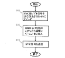
本発明の原理に係る例示的なフローチャートは、図2に示される。図3にも注意が向けられ、図3は、本発明の原理に係るビデオ信号を符号化する例示的な装置200を示す。本発明の概念に関連する部分のみが示される。装置200は、プロセッサに基づいたシステムであり、図3における破線のボックスの形式で示されるプロセッサ240とメモリ245とにより表されるように、1以上のプロセッサと関連するメモリとを有する。この文脈では、コンピュータプログラム又はソフトウェアは、プロセッサ240による実行のためにメモリ245に記憶され、たとえばSVCエンコーダ205を実現する。プロセッサ240は、1以上のプログラム内蔵式制御プロセッサを表し、これらは、送信機の機能の専用とされる必要がなく、たとえば、プロセッサ240は、送信機の他の機能を制御する場合がある。メモリ245は、たとえばランダムアクセスメモリ(RAM)、リードオンリメモリ(ROM)等といった記憶装置を表し、送信機の内部及び/又は外部にあり、必要に応じて揮発性及び/又は不揮発性である。
An exemplary flowchart according to the principles of the present invention is shown in FIG. Attention is also directed to FIG. 3, which shows an
装置200は、SVCエンコーダ205及び変調器210を有する。ビデオ信号204は、SVCエンコーダ205に印加される。SVCエンコーダは、本発明の原理に従ってビデオ信号204をエンコードし、SVC信号206を変調器210に供給する。変調器210は、(共に図3に示されない)アップコンバータ及びアンテナを介して送信のために変調された信号211を供給する。
The
図2を参照して、ステップ105では、図3のプロセッサ240は、ビデオ信号204を、ベースレイヤと少なくとも1つの他のレイヤを有するSVC信号206にエンコードする。特に、ステップ110では、IDRスライスがSVC信号206の他のレイヤよりも頻繁にベースレイヤに挿入されるように、プロセッサ240は、(たとえば図3における破線の形式で示される信号207を介して)図3のSVCエンコーダ205を制御する。特に、異なる空間レイヤで異なるIDRインターバルを規定する符号化パターンIBBP又はIPPPのように規定する符号化パラメータは、SVCエンコーダ205に印加される。ステップ115で、図3の変調器210は、SVC信号を送信する。
Referring to FIG. 2, at
図4を参照して、図2のフローチャートに従う図3のSVCエンコーダ205により形成される例示的なSVC信号206が示される。この例では、SVC信号206は、ベースレイヤ(D=0)及びエンハンスメントレイヤ(D=1)である2つのレイヤを有する。図4から観察されるように、ベースレイヤは、アクセスユニット1,4,7及び9においてIDRスライスを有し、エンハンスメントレイヤは、アクセスユニット1及び9においてIDRスライスを有する。係るように、矢印301により例示されるように時間TcでSVC信号206を伝送するチャネルに受信装置が切り替えたとき(最初の同調)、受信装置は、SVC信号206のベースレイヤの復号化を開始し、低減された解像度のビデオピクチャをユーザに供給することができる前に、矢印302により表されるように時間Twを待つ必要がある。したがって、レシーバは、より多くのランダムアクセスポイントを有するベースレイヤのビデオ符号化信号を即座に復号化することで、チューイン遅延とチャネル切り替え遅延とを低減することができる。図4から更に観察されるように、レシーバは、エンハンスメントレイヤを復号化し、より高い解像度のビデオピクチャをユーザに供給することができる前に、矢印303により表されるように時間Tdを待つ必要がある。
Referring to FIG. 4, an
両方のレイヤが同じIDR周波数を有する図1に示される例と比較したとき、本発明の概念は、制限されたパフォーマンスのロスによる低いビットレートで、同じセットの機能の改善を実現する能力を提供する。これは、ベースレイヤがビットストリームの全体のビットレートのごく一部のみを採用するときに特に当てはまる。たとえば、ベースレイヤ(D=0)としてのCIF(Common Intermediate Format)(720×288)の解像度、エンハンスメントレイヤ(D=1)としてのSD(Standard Definition)(720×480)の解像度について、ベースレイヤは、全体のビットレートの僅かなパーセンテージ(たとえば25%前後)のみを採用する。したがって、CIF解像度でIDR周波数を増加することで、ビットレートのオーバヘッドは、エンハンスメントレイヤのみで又は両方のレイヤでIDR周波数を増加することに比較して少ない。 Compared to the example shown in FIG. 1 where both layers have the same IDR frequency, the inventive concept provides the ability to achieve the same set of functional improvements at a lower bit rate due to limited performance loss To do. This is especially true when the base layer employs only a fraction of the overall bit rate of the bitstream. For example, for the resolution of CIF (Common Intermediate Format) (720 × 288) as the base layer (D = 0) and the resolution of SD (Standard Definition) (720 × 480) as the enhancement layer (D = 1), the base layer Only employs a small percentage of the overall bit rate (eg around 25%). Therefore, by increasing the IDR frequency at the CIF resolution, the bit rate overhead is small compared to increasing the IDR frequency only in the enhancement layer or in both layers.
SVCでは、エンハンスメントレイヤがベースレイヤ上に有するレイヤ間の予測の依存性のため、最初のターゲットとされる依存性の表現期間のパフォーマンスのロスを緩和することができる。たとえば、上述されたように、図4では、チャネル切り替え又は周波数の同調(チューンイン)がアクセスユニット番号3で生じたとき、デコーダは、アクセスユニット番号9までベースレイヤビットストリームを正しく復号化する。しかし、デコーダは、エンハンスメントレイヤの品質でビデオを再構成するのを助けるため、対応するエンハンスメントレイヤのアクセスユニットに含まれる情報を利用することができる。
In SVC, because of the prediction dependency between layers that the enhancement layer has on the base layer, it is possible to mitigate performance loss during the first target dependency expression period. For example, as described above, in FIG. 4, when channel switching or frequency tuning (tune-in) occurs at
なお、復号化の複雑度を低減するため、シングルループ復号化がSVC標準で規定されている。シングルループ復号化を可能にするため、エンコーダは、制約されたレイヤ間予測を採用する。これにより、エンハンスメントレイヤマクロブロック(MB)についてレイヤ間のイントラ予測の使用のみが可能とされ、このエンハンスメントレイヤマクロブロックに対して、共に位置される参照レイヤ信号がイントラ符号化される。参照レイヤのイントラ符号化されたMBを再構築するとき、インター符号化されたMBの再構築を回避するため、上位レイヤのレイヤ間予測のために使用される全てのレイヤは、制約されたイントラ予測を使用して符号化されることが更に必要とされる。 Note that single-loop decoding is defined in the SVC standard in order to reduce decoding complexity. To enable single-loop decoding, the encoder employs constrained inter-layer prediction. As a result, only intra-layer intra prediction can be used for the enhancement layer macroblock (MB), and the reference layer signals positioned together are intra-coded for the enhancement layer macroblock. When reconstructing the intra-coded MB of the reference layer, in order to avoid reconstructing the inter-coded MB, all layers used for higher layer inter-layer prediction must be constrained intra It is further required to be encoded using prediction.
本発明の原理によれば、IDRピクチャにおける増加は、ベースレイヤにおけるイントラ符号化されたMBの数を増加させる。それが有益であるとき、ベースレイヤIDRピクチャにおけるイントラ符号化されたMBは制約されたイントラ予測により強制的に符号化される。結果的に、エンハンスメントレイヤは、ベースレイヤからのレイヤ間のイントラ予測のため、より多くのイントラ符号化されたMBを有することができ、これにより、その符号化効率が潜在的に改善される。ベースレイヤでの係る符号化されたIDRピクチャにより、エンハンスメントレイヤでの高い符号化効率を得ることができる。ゲインは、ベースレイヤで符号化された余分のIDRピクチャのため、ビットレートの増加を相殺する。 In accordance with the principles of the present invention, an increase in IDR pictures increases the number of intra-coded MBs in the base layer. When it is beneficial, intra-coded MBs in base layer IDR pictures are forced to be coded with constrained intra prediction. As a result, the enhancement layer can have more intra-coded MBs due to intra-layer intra prediction from the base layer, which potentially improves its coding efficiency. With such an encoded IDR picture at the base layer, a high coding efficiency at the enhancement layer can be obtained. The gain cancels the bit rate increase due to extra IDR pictures encoded in the base layer.
ここで図5を参照して、本発明の原理に係るSVC信号を受信する例示的な装置が示される。本発明の概念に係る部分のみが示される。装置350は、(たとえば図3の装置200により送信された信号の受信されたバージョンである)受信された信号311により表されるように、本発明の原理に従うSVC信号を伝送する信号を受信する。装置350は、たとえば携帯電話、モバイルTV、セットトップボックス、デジタルTV(DTV)等を表す。装置350は、受信機355、プロセッサ360及びメモリ365を有する。かかるように、装置350は、プロセッサに基づいたシステムである。受信機355は、SVC信号を伝達するチャネルに同調するフロントエンド及び復調器を表す。受信機355は、信号311を受信し、そこから信号356を回復する。この信号356は、プロセッサ360により処理され、すなわちプロセッサ360は、SVC復号化を実行する。たとえば、本発明の原理に係るチャネル切り替え及びチャネルチューンインのための図6に示されるフローチャートによれば、プロセッサ360は、パス366を介してメモリ365に復号化されたビデオを供給する。復号化されたビデオは、装置350の一部であるか、又は装置350とは個別のディスプレイ(図示せず)に印加するためにメモリ365に記憶される。
Referring now to FIG. 5, an exemplary apparatus for receiving an SVC signal according to the principles of the present invention is shown. Only the part according to the concept of the present invention is shown.
図6を参照して、装置350における使用のために本発明の原理に係る例示的なフローチャートが示される。チャネルの切り替え又はあるチャネルへの同調に応じて、プロセッサ360は、最初の目標とされる依存性のレイヤへの復号化を設定する。この例では、これは、ステップ405において受信されたSVC信号のベースレイヤにより表される。しかし、本発明の概念はそのように限定されず、他の依存性のレイヤは、他の依存性のレイヤよりも多くのランダムアクセスポイントを有する限り、「最初にターゲットとされるレイヤ」として指定される。ステップ410では、プロセッサ360は、受信されたアクセスユニット(当該技術分野では、受信されたSVC NAL(Network Abstraction Layer)ユニットとも呼ばれる)からベースレイヤフレームを受信し、ステップ415では、受信されたベースレイヤフレームがIDRスライスであるかをチェックする。IDRスライスではない場合、プロセッサ360は、次のベースレイヤフレームを受信するためにステップ410に戻る。しかし、受信されたベースレイヤフレームがIDRスライスである場合、プロセッサ360は、低減された解像度であるがビデオ信号を供給するSVCベースレイヤの復号化を開始する。次いで、プロセッサ360は、ステップ425で、受信されたアクセスユニットからエンハンスメントレイヤのフレームを受信し、ステップ430で、受信されたエンハンスメントレイヤのフレームがIDRスライスであるかをチェックする。IDRスライスではない場合、プロセッサ360は、次のエンハンスメントレイヤのフレームを受信するためにステップ425に戻る。しかし、受信されたエンハンスメントレイヤフレームがIDRスライスである場合、プロセッサ360は、より高い解像度でビデオ信号を供給するため、ステップ435におけるSVCエンハンスメントレイヤの復号化を開始する。言い換えれば、現在の復号化レイヤの値よりも大きいdependency_idの値をもつ依存性のレイヤにおけるIDRスライスの検出に応じて、受信機は、検出されたIDRスライスをもつ依存性のレイヤにおける符号化ビデオを復号化する。さもなければ、受信機は、現在の依存性のレイヤを復号化し続ける。なお、ベースレイヤからのIDRがないとしても、エンハンスメントレイヤからのIDRがあれば、エンハンスメントレイヤの復号化を開始することができる。
Referring to FIG. 6, an exemplary flowchart according to the principles of the present invention for use in
なお、図6のフローチャートは、装置350による上位レイヤの処理を表す。たとえば、ステップ420においてベースレイヤの復号化がひとたび開始されると、これは、ステップ425及び430においてプロセッサ350がIDRスライスについてエンハンスメントレイヤをチェックするとしても、プロセッサ350により継続される。同様に、ステップ415において、ベースレイヤがIDRスライスについてチェックされ、次いで、ステップ430において、エンハンスメントレイヤがIDRスライスについてチェックされる。これらは、たとえばチャネル切り替え又はチューンインが図4の矢印309により表される時間で生じた場合に同じアクセスユニットからであり、この場合、次のアクセスユニット9は、両方のレイヤにおいてIDRスライスを有する。最後に、ベースレイヤと1つのエンハンスメントレイヤの文脈で例示されたが、図6のフローチャートは、1を超えるエンハンスメントレイヤに容易に拡張することができる。
Note that the flowchart of FIG. 6 represents the upper layer processing by the
上述されたように、本発明の原理によれば、スケーラブルビデオ符号化のピクチャタイプのコンフィギュレーションの方法が記載された。本発明の概念は、MPEG−SVCにより生成される圧縮されたビットストリームの誤り耐性を改善する(たとえば、ITU−T Recommendation H.264 Amendment 3: “Advanced video coding for generic audiovisual services: Scalable Video Coding”)。さらに、上述されたシステムが本発明の原理に従って符号化された係るビットストリームを伝送するとき、チューンイン遅延及びチャネル切り替え遅延を低減することができる。なお、本発明の概念は2レイヤの空間スケーラブルSVCビットストリームの環境で記載されたが、本発明の概念はそのように限定されず、SVC標準で規定されるSNR(信号対雑音比)スケーラビリティと同様に多数のスケーラブルレイヤに適用することができる。 As described above, according to the principles of the present invention, a picture type configuration method for scalable video coding has been described. The inventive concept improves the error resilience of compressed bitstreams generated by MPEG-SVC (eg, ITU-T Recommendation H.264 Amendment 3: “Advanced video coding for generic audiovisual services: Scalable Video Coding” ). Furthermore, when the system described above transmits such a bitstream encoded according to the principles of the present invention, tune-in delay and channel switching delay can be reduced. Although the concept of the present invention has been described in a two-layer spatial scalable SVC bitstream environment, the concept of the present invention is not so limited, and the SNR (signal-to-noise ratio) scalability defined by the SVC standard Similarly, it can be applied to a number of scalable layers.
上述の内容を考慮して、上述した内容は本発明の原理を単に例示したものであって、当業者は、本明細書に明示的に記載されていないが、本発明の原理を実施するものであって、本発明の範囲及び精神に含まれるものである様々な代替となる構成を創作することができる。たとえば、個別の機能エレメントの文脈で例示されるが、これら機能エレメントは、1以上の集積回路(IC)で実施される場合がある。同様に、個別のエレメントとして図示されているが、一部又は全部のエレメントは、たとえば図2及び図6等に示される1以上のステップに対応する関連するソフトウェアを実行するデジタルシグナルプロセッサであるプログラム内蔵型制御プロセッサで実現される場合がある。さらに、本発明の原理は、たとえばサテライト、ワイヤレスフィデリティ(Wi−Fi)、セルラー等といった他のタイプの通信システムに適用可能である。確かに、本発明の概念は、静止型受信機又は移動型受信機にも適用可能である。したがって、様々な変更が例示的な実施の形態になされ、特許請求の範囲により定義される本発明の精神及び範囲から逸脱することなしに他の構成が創作される場合があることを理解されたい。 In view of the foregoing, the foregoing is merely illustrative of the principles of the invention and is provided by those skilled in the art to implement the principles of the invention although not expressly described herein. However, various alternative configurations can be created that are within the scope and spirit of the present invention. For example, although illustrated in the context of individual functional elements, these functional elements may be implemented in one or more integrated circuits (ICs). Similarly, although illustrated as individual elements, some or all of the elements are programs that are digital signal processors that execute associated software corresponding to one or more steps shown, for example, in FIGS. May be implemented with a built-in control processor. Furthermore, the principles of the present invention are applicable to other types of communication systems such as satellites, wireless fidelity (Wi-Fi), cellular, etc. Certainly, the concept of the present invention can be applied to a stationary receiver or a mobile receiver. Accordingly, it should be understood that various modifications may be made to the exemplary embodiments and other configurations may be created without departing from the spirit and scope of the invention as defined by the claims. .
Claims (8)
複数のスケーラブルレイヤを有するビデオ符号化信号を供給するため、信号にスケーラブルビデオ符号化を施すステップと、前記複数のスケーラブルレイヤのうちの1つは、他のスケーラブルレイヤよりも多くのランダムアクセスポイントを有するために選択され、
スケーラブルビデオ符号化信号を送信するステップと、
を含む方法。 A method for transmitting a video signal,
Applying a scalable video coding to the signal to provide a video encoded signal having a plurality of scalable layers, and one of the plurality of scalable layers has more random access points than the other scalable layers; Selected to have and
Transmitting a scalable video encoded signal;
Including methods.
請求項1記載の方法。 The selected scalable layer is a base layer of the video encoded signal.
The method of claim 1.
複数のスケーラブルレイヤを含むスケーラブルビデオ符号化信号を受信するステップと、
多くのランダムアクセスポイントを有する依存性のレイヤに対する復号化を設定するステップと、前記依存性のレイヤは、現在の復号化レイヤであり、
IDR(Instantaneous Decoder Refresh)スライスについて前記多くのランダムアクセスポイントを有するスケーラブルレイヤからのフレームをチェックするステップと、
前記多くのランダムアクセスポイントを有するスケーラブルレイヤにおけるIDRスライスの検出に応じて、前記多くのランダムアクセスポイントを有するスケーラブルレイヤにおける前記符号化されたビデオを復号化するステップと、
IDRスライスの他のスケーラブルレイヤからのフレームをチェックするステップと、
前記現在の復号化レイヤの値よりも大きいdependency_idの値をもつ依存性のレイヤにおけるIDRスライスの検出に応じて、前記依存性のレイヤにおける符号化されたビデオを復号化するステップと、
を含む方法。 A method for use in an apparatus for performing channel switching or tuning to a channel, comprising:
Receiving a scalable video encoded signal including a plurality of scalable layers;
Configuring decoding for a dependency layer having many random access points, the dependency layer being a current decoding layer;
Checking frames from the scalable layer with said many random access points for IDR (Instantaneous Decoder Refresh) slices;
Decoding the encoded video in the scalable layer with many random access points in response to detection of an IDR slice in the scalable layer with many random access points;
Checking frames from other scalable layers of the IDR slice;
Decoding the encoded video in the dependency layer in response to detecting an IDR slice in the dependency layer having a dependency_id value greater than the current decoding layer value;
Including methods.
請求項3記載の方法。 The scalable layer having many random access points is a base layer of the scalable video encoded signal.
The method of claim 3.
前記ビデオ符号化された信号の送信において使用される変調器と、
を含む装置。 A scalable video encoder that provides a video encoded signal having a plurality of scalable layers, and one of the plurality of scalable layers is selected to have more random access points than the other scalable layers;
A modulator used in transmission of the video encoded signal;
Including the device.
請求項5記載の装置。 The scalable layer selected is a base layer of the video encoded signal.
The apparatus of claim 5.
前記他のスケーラブルレイヤからのランダムアクセスポイントが利用可能になるまで、前記チャネルへの切り替え又は前記チャネルへの同調に応じて、多くのランダムアクセスポイントを有するために選択されたスケーラブルレイヤを復号化するプロセッサと、
を有する装置。 Receiving means for supplying a scalable video encoded signal from a channel; and the scalable video encoded signal includes a plurality of scalable layers selected so that one scalable layer has more random access points than the other scalable layers Have
Decode the scalable layer selected to have many random access points in response to switching to the channel or tuning to the channel until random access points from the other scalable layer become available A processor;
Having a device.
請求項7記載の装置。 The selected scalable layer is a base layer of the scalable video encoded signal.
The apparatus of claim 7.
Applications Claiming Priority (2)
| Application Number | Priority Date | Filing Date | Title |
|---|---|---|---|
| US182207P | 2007-11-05 | 2007-11-05 | |
| PCT/US2008/012303 WO2009061363A2 (en) | 2007-11-05 | 2008-10-30 | A scalable video coding method for fast channel change and increased error resilience |
Publications (2)
| Publication Number | Publication Date |
|---|---|
| JP2011503968A true JP2011503968A (en) | 2011-01-27 |
| JP2011503968A5 JP2011503968A5 (en) | 2011-09-22 |
Family
ID=40626379
Family Applications (1)
| Application Number | Title | Priority Date | Filing Date |
|---|---|---|---|
| JP2010532055A Withdrawn JP2011503968A (en) | 2007-11-05 | 2008-10-30 | A scalable video coding method for fast channel switching and increased error resilience |
Country Status (8)
| Country | Link |
|---|---|
| US (1) | US20100232520A1 (en) |
| EP (1) | EP2210420A2 (en) |
| JP (1) | JP2011503968A (en) |
| KR (1) | KR20100097124A (en) |
| CN (1) | CN101849417A (en) |
| CA (1) | CA2704490A1 (en) |
| MX (1) | MX2010004935A (en) |
| WO (1) | WO2009061363A2 (en) |
Cited By (1)
| Publication number | Priority date | Publication date | Assignee | Title |
|---|---|---|---|---|
| JP2016518764A (en) * | 2013-04-05 | 2016-06-23 | クゥアルコム・インコーポレイテッドQualcomm Incorporated | Cross-layer registration in multi-layer video coding |
Families Citing this family (25)
| Publication number | Priority date | Publication date | Assignee | Title |
|---|---|---|---|---|
| CN102106156B (en) * | 2008-07-26 | 2013-06-19 | 汤姆逊许可证公司 | Real-time transport protocol (RTP) packetization method for fast channel change applications using scalable video coding (SVC) |
| JP5667773B2 (en) * | 2010-03-18 | 2015-02-12 | キヤノン株式会社 | Information creating apparatus and control method thereof |
| KR101151018B1 (en) * | 2010-06-18 | 2012-05-30 | 동국대학교 산학협력단 | Appratus and method for transfering bitstream |
| CN103024592B (en) * | 2011-09-22 | 2015-11-25 | 华为技术有限公司 | The method of video data burst, Apparatus and system |
| US9131245B2 (en) | 2011-09-23 | 2015-09-08 | Qualcomm Incorporated | Reference picture list construction for video coding |
| CN103200399B (en) * | 2012-01-04 | 2016-08-31 | 北京大学 | The method and device of control video quality fluctuation based on scalable video |
| US9219913B2 (en) * | 2012-06-13 | 2015-12-22 | Qualcomm Incorporated | Inferred base layer block for TEXTURE—BL mode in HEVC based single loop scalable video coding |
| US9912941B2 (en) | 2012-07-02 | 2018-03-06 | Sony Corporation | Video coding system with temporal layers and method of operation thereof |
| US20140003534A1 (en) * | 2012-07-02 | 2014-01-02 | Sony Corporation | Video coding system with temporal scalability and method of operation thereof |
| US10110890B2 (en) | 2012-07-02 | 2018-10-23 | Sony Corporation | Video coding system with low delay and method of operation thereof |
| US9491459B2 (en) * | 2012-09-27 | 2016-11-08 | Qualcomm Incorporated | Base layer merge and AMVP modes for video coding |
| KR101388591B1 (en) * | 2012-11-07 | 2014-04-24 | 한라대학교산학협력단 | Fec packet allocating method and apparataus, and server and client apparatus employing the same |
| KR20150096410A (en) | 2012-12-17 | 2015-08-24 | 톰슨 라이센싱 | Robust digital channels |
| US9936226B2 (en) | 2012-12-17 | 2018-04-03 | Thomson Licensing | Robust digital channels |
| US9648353B2 (en) * | 2013-04-04 | 2017-05-09 | Qualcomm Incorporated | Multiple base layer reference pictures for SHVC |
| US9596486B2 (en) | 2013-04-05 | 2017-03-14 | Qualcomm Incorporated | IRAP access units and bitstream switching and splicing |
| US9674533B2 (en) | 2013-04-05 | 2017-06-06 | Qualcomm Incorporated | Picture alignments in multi-layer video coding |
| US9807421B2 (en) * | 2013-04-05 | 2017-10-31 | Sharp Kabushiki Kaisha | NAL unit type restrictions |
| US10003815B2 (en) | 2013-06-03 | 2018-06-19 | Qualcomm Incorporated | Hypothetical reference decoder model and conformance for cross-layer random access skipped pictures |
| US10547834B2 (en) * | 2014-01-08 | 2020-01-28 | Qualcomm Incorporated | Support of non-HEVC base layer in HEVC multi-layer extensions |
| JP6348188B2 (en) | 2014-06-18 | 2018-06-27 | テレフオンアクチーボラゲット エルエム エリクソン(パブル) | Robust encoding and decoding of pictures in video |
| KR101895176B1 (en) * | 2014-06-18 | 2018-09-04 | 텔레폰악티에볼라겟엘엠에릭슨(펍) | Dependent random access point pictures |
| US10542288B2 (en) * | 2014-06-18 | 2020-01-21 | Telefonaktiebolaget Lm Ericsson (Publ) | Random access in a video bitstream |
| US11184624B2 (en) * | 2016-05-19 | 2021-11-23 | Qualcomm Incorporated | Regional random access in pictures |
| WO2021188451A1 (en) * | 2020-03-16 | 2021-09-23 | Bytedance Inc. | Random access point access unit in scalable video coding |
Family Cites Families (3)
| Publication number | Priority date | Publication date | Assignee | Title |
|---|---|---|---|---|
| CN1973550B (en) * | 2004-07-07 | 2010-08-18 | 汤姆森许可贸易公司 | Fast channel change in digital video broadcast systems over DSL using redundant video streams |
| KR100643291B1 (en) * | 2005-04-14 | 2006-11-10 | 삼성전자주식회사 | Apparatus and method of video encoding and decoding for minimizing random access delay |
| KR101407571B1 (en) * | 2006-03-27 | 2014-06-16 | 세종대학교산학협력단 | Scalable video encoding and decoding method using switching pictures and apparatus thereof |
-
2008
- 2008-10-30 KR KR1020107011966A patent/KR20100097124A/en not_active Application Discontinuation
- 2008-10-30 JP JP2010532055A patent/JP2011503968A/en not_active Withdrawn
- 2008-10-30 EP EP08847636A patent/EP2210420A2/en not_active Withdrawn
- 2008-10-30 WO PCT/US2008/012303 patent/WO2009061363A2/en active Application Filing
- 2008-10-30 US US12/734,279 patent/US20100232520A1/en not_active Abandoned
- 2008-10-30 CN CN200880114758A patent/CN101849417A/en active Pending
- 2008-10-30 CA CA2704490A patent/CA2704490A1/en not_active Abandoned
- 2008-10-30 MX MX2010004935A patent/MX2010004935A/en not_active Application Discontinuation
Cited By (1)
| Publication number | Priority date | Publication date | Assignee | Title |
|---|---|---|---|---|
| JP2016518764A (en) * | 2013-04-05 | 2016-06-23 | クゥアルコム・インコーポレイテッドQualcomm Incorporated | Cross-layer registration in multi-layer video coding |
Also Published As
| Publication number | Publication date |
|---|---|
| MX2010004935A (en) | 2010-05-24 |
| CA2704490A1 (en) | 2009-05-14 |
| WO2009061363A2 (en) | 2009-05-14 |
| WO2009061363A3 (en) | 2009-08-13 |
| EP2210420A2 (en) | 2010-07-28 |
| KR20100097124A (en) | 2010-09-02 |
| US20100232520A1 (en) | 2010-09-16 |
| CN101849417A (en) | 2010-09-29 |
Similar Documents
| Publication | Publication Date | Title |
|---|---|---|
| JP2011503968A (en) | A scalable video coding method for fast channel switching and increased error resilience | |
| JP5155449B2 (en) | Real-time transport protocol (RTP) packetization method for fast channel change applications using scalable video coding (SVC) | |
| US20110110418A1 (en) | Scalable video coding method for fast channel change to increase coding efficiency | |
| US8340183B2 (en) | Digital multimedia channel switching | |
| US8396082B2 (en) | Time-interleaved simulcast for tune-in reduction | |
| CN101438520B (en) | Multi-program viewing in a wireless apparatus | |
| US20110109810A1 (en) | Method an apparatus for fast channel change using a scalable video coding (svc) stream | |
| US20100150249A1 (en) | Staggercasting with no channel change delay | |
| US20080301742A1 (en) | Time-interleaved simulcast for tune-in reduction | |
| KR20180113977A (en) | Methodologies and apparatus for reducing delays in receiving, processing, or switching content | |
| US20140245361A1 (en) | Multilevel satellite broadcasting system for providing hierarchical satellite broadcasting and operation method of the same | |
| KR20070006006A (en) | System for digital multimedia broadcast performance improvement with watermark and error concealment | |
| Jain et al. | Digital television and video compression | |
| Roy | Implementation of a Personal Digital Radio Recorder for Digital Multimedia Broadcasting by Adapting the Open-Source Personal Digital Video Recorder Software MythTV | |
| EP2151075A2 (en) | Time-interleaved simulcast for tune-in reduction |
Legal Events
| Date | Code | Title | Description |
|---|---|---|---|
| A521 | Written amendment |
Free format text: JAPANESE INTERMEDIATE CODE: A523 Effective date: 20110808 |
|
| A621 | Written request for application examination |
Free format text: JAPANESE INTERMEDIATE CODE: A621 Effective date: 20110808 |
|
| A761 | Written withdrawal of application |
Free format text: JAPANESE INTERMEDIATE CODE: A761 Effective date: 20120417 |