JP2011503541A - Small magnet and RF coil for magnetic resonance relaxation measurements - Google Patents
Small magnet and RF coil for magnetic resonance relaxation measurements Download PDFInfo
- Publication number
- JP2011503541A JP2011503541A JP2010532083A JP2010532083A JP2011503541A JP 2011503541 A JP2011503541 A JP 2011503541A JP 2010532083 A JP2010532083 A JP 2010532083A JP 2010532083 A JP2010532083 A JP 2010532083A JP 2011503541 A JP2011503541 A JP 2011503541A
- Authority
- JP
- Japan
- Prior art keywords
- probe head
- magnetic field
- region
- coil
- excitable
- Prior art date
- Legal status (The legal status is an assumption and is not a legal conclusion. Google has not performed a legal analysis and makes no representation as to the accuracy of the status listed.)
- Pending
Links
Images


Classifications
-
- G—PHYSICS
- G01—MEASURING; TESTING
- G01R—MEASURING ELECTRIC VARIABLES; MEASURING MAGNETIC VARIABLES
- G01R33/00—Arrangements or instruments for measuring magnetic variables
- G01R33/20—Arrangements or instruments for measuring magnetic variables involving magnetic resonance
- G01R33/44—Arrangements or instruments for measuring magnetic variables involving magnetic resonance using nuclear magnetic resonance [NMR]
- G01R33/448—Relaxometry, i.e. quantification of relaxation times or spin density
-
- G—PHYSICS
- G01—MEASURING; TESTING
- G01N—INVESTIGATING OR ANALYSING MATERIALS BY DETERMINING THEIR CHEMICAL OR PHYSICAL PROPERTIES
- G01N24/00—Investigating or analyzing materials by the use of nuclear magnetic resonance, electron paramagnetic resonance or other spin effects
- G01N24/08—Investigating or analyzing materials by the use of nuclear magnetic resonance, electron paramagnetic resonance or other spin effects by using nuclear magnetic resonance
-
- G—PHYSICS
- G01—MEASURING; TESTING
- G01R—MEASURING ELECTRIC VARIABLES; MEASURING MAGNETIC VARIABLES
- G01R33/00—Arrangements or instruments for measuring magnetic variables
- G01R33/20—Arrangements or instruments for measuring magnetic variables involving magnetic resonance
- G01R33/24—Arrangements or instruments for measuring magnetic variables involving magnetic resonance for measuring direction or magnitude of magnetic fields or magnetic flux
- G01R33/243—Spatial mapping of the polarizing magnetic field
-
- G—PHYSICS
- G01—MEASURING; TESTING
- G01R—MEASURING ELECTRIC VARIABLES; MEASURING MAGNETIC VARIABLES
- G01R33/00—Arrangements or instruments for measuring magnetic variables
- G01R33/20—Arrangements or instruments for measuring magnetic variables involving magnetic resonance
- G01R33/28—Details of apparatus provided for in groups G01R33/44 - G01R33/64
- G01R33/30—Sample handling arrangements, e.g. sample cells, spinning mechanisms
- G01R33/302—Miniaturized sample handling arrangements for sampling small quantities, e.g. flow-through microfluidic NMR chips
-
- G—PHYSICS
- G01—MEASURING; TESTING
- G01R—MEASURING ELECTRIC VARIABLES; MEASURING MAGNETIC VARIABLES
- G01R33/00—Arrangements or instruments for measuring magnetic variables
- G01R33/20—Arrangements or instruments for measuring magnetic variables involving magnetic resonance
- G01R33/28—Details of apparatus provided for in groups G01R33/44 - G01R33/64
- G01R33/30—Sample handling arrangements, e.g. sample cells, spinning mechanisms
- G01R33/307—Sample handling arrangements, e.g. sample cells, spinning mechanisms specially adapted for moving the sample relative to the MR system, e.g. spinning mechanisms, flow cells or means for positioning the sample inside a spectrometer
-
- G—PHYSICS
- G01—MEASURING; TESTING
- G01R—MEASURING ELECTRIC VARIABLES; MEASURING MAGNETIC VARIABLES
- G01R33/00—Arrangements or instruments for measuring magnetic variables
- G01R33/20—Arrangements or instruments for measuring magnetic variables involving magnetic resonance
- G01R33/28—Details of apparatus provided for in groups G01R33/44 - G01R33/64
- G01R33/38—Systems for generation, homogenisation or stabilisation of the main or gradient magnetic field
- G01R33/3806—Open magnet assemblies for improved access to the sample, e.g. C-type or U-type magnets
-
- G—PHYSICS
- G01—MEASURING; TESTING
- G01R—MEASURING ELECTRIC VARIABLES; MEASURING MAGNETIC VARIABLES
- G01R33/00—Arrangements or instruments for measuring magnetic variables
- G01R33/20—Arrangements or instruments for measuring magnetic variables involving magnetic resonance
- G01R33/28—Details of apparatus provided for in groups G01R33/44 - G01R33/64
- G01R33/38—Systems for generation, homogenisation or stabilisation of the main or gradient magnetic field
- G01R33/383—Systems for generation, homogenisation or stabilisation of the main or gradient magnetic field using permanent magnets
-
- G—PHYSICS
- G01—MEASURING; TESTING
- G01R—MEASURING ELECTRIC VARIABLES; MEASURING MAGNETIC VARIABLES
- G01R33/00—Arrangements or instruments for measuring magnetic variables
- G01R33/20—Arrangements or instruments for measuring magnetic variables involving magnetic resonance
- G01R33/28—Details of apparatus provided for in groups G01R33/44 - G01R33/64
- G01R33/32—Excitation or detection systems, e.g. using radio frequency signals
- G01R33/34—Constructional details, e.g. resonators, specially adapted to MR
- G01R33/34046—Volume type coils, e.g. bird-cage coils; Quadrature bird-cage coils; Circularly polarised coils
- G01R33/34053—Solenoid coils; Toroidal coils
-
- G—PHYSICS
- G01—MEASURING; TESTING
- G01R—MEASURING ELECTRIC VARIABLES; MEASURING MAGNETIC VARIABLES
- G01R33/00—Arrangements or instruments for measuring magnetic variables
- G01R33/20—Arrangements or instruments for measuring magnetic variables involving magnetic resonance
- G01R33/44—Arrangements or instruments for measuring magnetic variables involving magnetic resonance using nuclear magnetic resonance [NMR]
- G01R33/46—NMR spectroscopy
- G01R33/465—NMR spectroscopy applied to biological material, e.g. in vitro testing
Abstract
【課題】持ち運びおよび/または埋め込みおよび/または一回きりの使用が可能な、小型かつ安価な磁気共鳴システム用のプローブヘッド、および当該プローブヘッドを組み立てる方法を提供する。
【解決手段】本発明の磁気共鳴システム用のプローブヘッドは、磁場を生成する磁石または磁場生成手段、サンプル領域が収まり得る空間、対応する検出領域が励起可能領域と少なくとも部分的に重複するように構成かつ位置決めされたRFコイルを備えている。磁場は不均一であり、サンプル領域が収まる空間およびRFコイルは、サンプル領域の位置に対応した磁場分布にとって最適であるRFパルスの周波数帯域幅に応じて、構成かつ位置決めされる。このようにして、検出領域またはサンプル領域に送入されたサンプルから、緩和測定パラメータを得る。
【選択図】図1PROBLEM TO BE SOLVED: To provide a probe head for a small and inexpensive magnetic resonance system that can be carried and / or embedded and / or used once, and a method for assembling the probe head.
A probe head for a magnetic resonance system according to the present invention includes a magnet or magnetic field generating means for generating a magnetic field, a space in which a sample region can be accommodated, and a corresponding detection region at least partially overlapping an excitable region. A constructed and positioned RF coil is provided. The magnetic field is non-uniform and the space in which the sample region fits and the RF coil are configured and positioned according to the frequency bandwidth of the RF pulse that is optimal for the magnetic field distribution corresponding to the location of the sample region. In this way, relaxation measurement parameters are obtained from the sample delivered to the detection region or sample region.
[Selection] Figure 1
Description
本願は、2007年11月6日出願の米国特許仮出願第61/002,022号の優先権および利益、ならびに2007年12月21日出願の米国特許仮出願第61/008,991号の優先権および利益を主張する。これら先行する特許出願の全内容は、参照により本明細書に組み込んだものとする。 This application claims the priority and benefit of US Provisional Patent Application No. 61 / 002,022 filed on November 6, 2007, and the priority and benefit of US Patent Provisional Application No. 61 / 008,991 filed on December 21, 2007. Insist. The entire contents of these prior patent applications are hereby incorporated by reference.
本発明は、持ち運び型の磁気共鳴緩和計に用いられる小型のプローブヘッド、およびこれを組み立てる方法に関する。 The present invention relates to a small probe head used in a portable magnetic resonance relaxation meter and a method for assembling the probe head.
核磁気共鳴(NMR)システムは、サンプルに含まれる原子核の核磁気共鳴を利用するものであり、サンプルおよびサンプル成分に関する多種多様な情報を提供できるシステムとして知られている。このようなシステムには、例えば、磁気共鳴画像(MRI)装置、磁気共鳴分光計、磁気共鳴緩和計などが含まれる。核磁気共鳴現象を発生させるには、磁場の存在下でのRF電磁波による励起が必要である。したがって、核磁気共鳴(NMR)システムは、磁石とRFコイルを一般的に備える。磁石とRFコイルは、システムにおける別々の構成品とされるか、またはプローブヘッド内で組み合わせて使用される。 A nuclear magnetic resonance (NMR) system utilizes nuclear magnetic resonance of nuclei contained in a sample, and is known as a system that can provide a wide variety of information about a sample and sample components. Such systems include, for example, magnetic resonance imaging (MRI) devices, magnetic resonance spectrometers, magnetic resonance relaxometers, and the like. In order to generate a nuclear magnetic resonance phenomenon, excitation by an RF electromagnetic wave in the presence of a magnetic field is necessary. Thus, a nuclear magnetic resonance (NMR) system typically comprises a magnet and an RF coil. The magnet and RF coil are either separate components in the system or used in combination within the probe head.
磁気共鳴システムにおいて好ましい磁石とは、磁場均一性および磁場強度がともに優れた磁石である。これらの要件を満たす公知の磁石は、典型的に、大型および/または高価である。よって、このような磁石は、持ち運び型の装置および/または埋め込み型の装置に適しておらず、および/または使い捨てプローブヘッドの一部分として適していない。これらの理由から、持ち運びおよび/または埋め込みおよび/または一回きりの使用が可能な、小型かつ安価な磁気共鳴システム用のプローブヘッドが望まれている。 A preferable magnet in the magnetic resonance system is a magnet excellent in both magnetic field uniformity and magnetic field strength. Known magnets that meet these requirements are typically large and / or expensive. Thus, such magnets are not suitable for portable and / or implantable devices and / or are not suitable as part of a disposable probe head. For these reasons, a probe head for a magnetic resonance system that is small and inexpensive that can be carried and / or implanted and / or used once is desired.
本発明にかかるプローブヘッドおよびプローブヘッドを組み立てる方法により、現行の磁気共鳴(MR)システムの持ち運び性に関する課題、および/または埋込みに関する課題、および/または磁気共鳴(MR)システム用のプローブヘッドとしての使い捨て性に関する課題を解決することができる。本発明が提供するプローブヘッドは、特に磁気共鳴緩和測定に適しているが、これに限定されない。 As a probe head and a method of assembling a probe head according to the present invention, the problems relating to portability and / or implantation of current magnetic resonance (MR) systems and / or as probe heads for magnetic resonance (MR) systems The problem about disposableness can be solved. The probe head provided by the present invention is particularly suitable for magnetic resonance relaxation measurement, but is not limited thereto.
一実施態様は、磁気共鳴緩和計に用いられる小型のプローブヘッドである。このプローブヘッドは、(a)磁場を生成する少なくとも1つの磁石または磁場生成手段と;(b)サンプル領域が収まり得る空間とを備え、前記サンプル領域は対応する励起可能領域を含んでおり;さらに、(c)対応する検出領域を有しており、その検出領域が励起可能領域と少なくとも部分的に重複するように構成かつ位置決めされたRFコイルとを備えている。前記生成される磁場は不均一であり、前記サンプル領域が収まる空間および前記RFコイルは、前記サンプル領域の位置に対応した磁場分布にとって最適であるRFパルスに応じて、構成(すなわち、これに適合するように構成され)かつ位置決めされている。このようなプローブヘッドは、前記検出領域に含まれるサンプルから、緩和測定パラメータが得られるように最適化されている。 One embodiment is a small probe head used in a magnetic resonance relaxometer. The probe head comprises (a) at least one magnet or magnetic field generating means for generating a magnetic field; and (b) a space in which the sample region can be accommodated, the sample region including a corresponding excitable region; And (c) an RF coil having a corresponding detection region and configured and positioned so that the detection region at least partially overlaps the excitable region. The generated magnetic field is inhomogeneous and the space in which the sample region fits and the RF coil are configured (ie adapted to this) depending on the RF pulse that is optimal for the magnetic field distribution corresponding to the location of the sample region. And is positioned. Such a probe head is optimized so that relaxation measurement parameters can be obtained from a sample included in the detection region.
別の実施態様は、磁気共鳴緩和測定用のプローブヘッドである。この小型のプローブヘッドは、(a)ヨークに取り付けられた2つの磁石または磁場生成手段と、(b)サンプル領域が収まり得る空間とを備え、一方の磁石または磁場生成手段のS極面が他方の磁石または磁場生成手段のN極面に対向して前記磁石間または前記磁場生成手段間にギャップを形成し、このギャップ内に磁場を生成するとともに、前記サンプル領域は対応する励起可能領域を含んでおり;さらに、(c)RFコイルとを備えており、前記RFコイルは、前記ギャップ内に存在し、ある長さのRFパルスを発生するように構成されており、かつ、対応する検出領域を有しており、その検出領域が前記ギャップ内において前記励起可能領域と少なくとも部分的に重複するように位置決めかつ構成されている。前記生成される磁場は不均一である。さらに、前記サンプル領域が収まる空間および前記RFコイルは、前記サンプル領域の位置に対応した磁場分布にとって最適であるRFパルスの周波数帯域幅に応じて、構成かつ位置決めされている。このようにして、前記プローブヘッドは、前記サンプル領域に含まれるサンプルから、緩和測定パラメータが得られるように最適化されている。 Another embodiment is a probe head for measuring magnetic resonance relaxation. This small probe head includes (a) two magnets or magnetic field generating means attached to a yoke, and (b) a space in which a sample region can be accommodated, and the S pole surface of one magnet or magnetic field generating means is the other. A gap is formed between the magnets or between the magnetic field generating means so as to face the N pole surface of the magnet or the magnetic field generating means, and a magnetic field is generated in the gap, and the sample region includes a corresponding excitable region. And (c) an RF coil, the RF coil being in the gap, configured to generate an RF pulse of a length, and a corresponding detection region And the detection region is positioned and configured to at least partially overlap the excitable region in the gap. The generated magnetic field is inhomogeneous. Further, the space in which the sample region is accommodated and the RF coil are configured and positioned according to the frequency bandwidth of the RF pulse that is optimal for the magnetic field distribution corresponding to the position of the sample region. In this way, the probe head is optimized to obtain relaxation measurement parameters from the sample contained in the sample region.
さらに、本発明は、磁気共鳴緩和測定用のプローブヘッドを組み立てる方法を提供する。一実施態様は、磁気共鳴緩和計に用いられるプローブヘッドの組立方法である。この方法は、(a)磁場を生成する少なくとも1つの磁石または磁場生成手段を用意するステップと、(b)RFコイルを用意するステップと、(c)前記RFコイルを、その対応する検出領域が励起可能領域と少なくとも部分的に重複するように位置決めするステップと、(d)関連する励起可能領域を有するサンプル領域が収まり得る空間を位置決めするステップと、(e)前記サンプル領域のための空間および前記RFコイルを、前記検出領域の位置に対応した磁場分布にとって最適であるRFパルスに応じて構成するステップとを備えている。このようにして、前記プローブヘッドは、前記サンプル領域に含まれるサンプルから、緩和測定パラメータが得られるように最適化されている。 Furthermore, the present invention provides a method for assembling a probe head for measuring magnetic resonance relaxation. One embodiment is a method for assembling a probe head used in a magnetic resonance relaxation meter. The method includes (a) preparing at least one magnet or magnetic field generating means for generating a magnetic field, (b) preparing an RF coil, and (c) the RF coil having a corresponding detection region. Positioning to at least partially overlap the excitable region; (d) positioning a space in which a sample region having an associated excitable region can fit; (e) a space for the sample region; Configuring the RF coil in accordance with an RF pulse that is optimal for a magnetic field distribution corresponding to the position of the detection region. In this way, the probe head is optimized so that relaxation measurement parameters can be obtained from the sample contained in the sample region.
さらなる実施態様は、持ち運び式の磁気共鳴緩和測定に用いる小型のプローブヘッドを組み立てる方法である。この方法は、(a)2つの磁石または磁場生成手段をヨークに取り付けて、一方の磁石または磁場生成手段のS極面を他方の磁石または磁場生成手段のN極面に対向させて磁石間または磁場生成手段間にギャップを形成し前記ギャップにおいて磁場を生成するステップと、(b)対応する励起可能領域を含むサンプル領域が収まり得る空間を位置決めするステップと、(c)対応する検出領域を有したRFコイルを、前記ギャップ内に位置決めするステップとを備え、前記RFコイルは所定の長さのRFパルスを発生するように構成され、かつ、その検出領域が前記ギャップ内において励起可能領域と少なくとも部分的に重複するように構成されている。このようにして、前記プローブヘッドは、前記サンプル領域に含まれるサンプルから、緩和測定パラメータが得られるように最適化されている。 A further embodiment is a method of assembling a small probe head for use in portable magnetic resonance relaxation measurements. In this method, (a) two magnets or magnetic field generating means are attached to a yoke, and the S pole face of one magnet or magnetic field generating means is opposed to the N pole face of the other magnet or magnetic field generating means. Forming a gap between the magnetic field generating means and generating a magnetic field in the gap; (b) positioning a space in which a sample region including a corresponding excitable region can be accommodated; and (c) having a corresponding detection region. Positioning the RF coil in the gap, wherein the RF coil is configured to generate an RF pulse of a predetermined length, and its detection area is at least an excitable area within the gap. It is comprised so that it may overlap partially. In this way, the probe head is optimized to obtain relaxation measurement parameters from the sample contained in the sample region.
前述の内容は、添付の図面に示した本発明の例示的な実施態様についての以下の詳細な説明から明らかになるであろう。図面における同一の符合は、異なる図をとおして同一の箇所(構成要素)を表すものとする。図面は必ずしも正確な縮尺ではなく、むしろ、本発明の実施態様を示すことに重点を置いている。 The foregoing will become apparent from the following detailed description of exemplary embodiments of the invention illustrated in the accompanying drawings. The same reference numerals in the drawings represent the same portion (component) through different drawings. The drawings are not necessarily to scale, emphasis instead being placed upon illustrating embodiments of the invention.
本発明にかかるプローブヘッドは、磁石および/または磁場生成手段と、少なくとも1つのRFコイルとを備えている。また、本発明にかかるプローブヘッドは、磁石とRFコイルの従来の組合せよりも遥かに小型かつ低コストである。 The probe head according to the present invention includes a magnet and / or a magnetic field generating means and at least one RF coil. The probe head according to the present invention is much smaller and less expensive than the conventional combination of a magnet and an RF coil.
プローブヘッドの重量と寸法は、持ち運び型のMR機器にとって重要なファクター(因子)である。例えば、軽量化や小型化は、システムの開発、製造、コストや設置に大きな意味合いを持つ。小型のプローブは、例えば、生体内に埋め込み可能な装置、材料試験用の埋込み型センサ、オンラインプロセスモニタリング(on-line process monitoring)用のセンサなどに活用することができる。さらに、本発明が提供する小型のプローブヘッドは低コストで作製できるので、使い捨て可能なプローブヘッドが役立つような用途にも利用することができる。 The weight and dimensions of the probe head are important factors for portable MR equipment. For example, weight reduction and downsizing have great implications for system development, manufacturing, cost and installation. The small probe can be used for, for example, a device that can be implanted in a living body, an implantable sensor for material testing, a sensor for on-line process monitoring. Furthermore, since the small probe head provided by the present invention can be manufactured at low cost, it can be used for applications where a disposable probe head is useful.
本発明の特徴の1つとして、磁石とラジオ周波数(RF)コイルを備えた磁気共鳴(MR)プローブヘッドのコンパクト化が挙げられる。詳細には、本発明は、プローブヘッドを用いた磁気共鳴シグナルレベル(特に、磁気共鳴緩和パラメータおよび磁気共鳴緩和時間)の測定を可能としながら、そのプローブヘッドの構成品の寸法を大幅に減少させるという課題に取り組んだものである。その結果、従来の磁気共鳴(MR)分光計の代わりに、緩和測定に特化したプローブヘッドを設計(製作)することにより、大幅な小型化および劇的なコスト削減の実現に至った。 One feature of the present invention is the compactness of a magnetic resonance (MR) probe head having a magnet and a radio frequency (RF) coil. In particular, the present invention significantly reduces the dimensions of the probe head components while allowing measurement of magnetic resonance signal levels (particularly magnetic resonance relaxation parameters and magnetic resonance relaxation times) using the probe head. It tackles the problem. As a result, instead of a conventional magnetic resonance (MR) spectrometer, a probe head specialized for relaxation measurement was designed (manufactured), thereby realizing a significant reduction in size and dramatic cost reduction.
磁石の形態およびヨークの設計は、初めに磁石およびヨーク構成による磁場強度の分布を理論的に推測することにより、必要に応じて決定できる。適切な磁場強度については、後で説明する。これは、当該技術分野で知られている一般的な分析方法を用いることで達成できる。 The magnet configuration and yoke design can be determined as needed by first theoretically estimating the magnetic field strength distribution due to the magnet and yoke configuration. An appropriate magnetic field strength will be described later. This can be achieved by using common analytical methods known in the art.
一実施態様では、少なくとも1つの磁石または磁場生成手段が、ギャップにおいて磁場を生成するように形成および/または構成されている。ある実施態様では、RFコイルが、このような構成のギャップ内に部分的または全体的に収まるように位置決めされている。 In one embodiment, at least one magnet or magnetic field generating means is formed and / or configured to generate a magnetic field in the gap. In some embodiments, the RF coil is positioned to partially or fully fit within the gap of such a configuration.
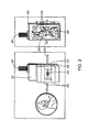
磁石の所与の形態として、例えば、図1、図2および図3に概略的に示したような2つの対向する永久磁石の形態、ならびに図4に示したハルバッハ磁石の形態が挙げられる。x方向、y方向およびz方向の磁場は、当該技術分野で知られている一般的な方法を用いることで測定できる。例えば、ガウスメータプローブを磁石に対して一定位置に固定し、この磁石を三軸ステージを用いて段階的に移動させながら磁場強度を位置の関数として(位置に対する磁場強度の変化を)記録することにより、磁場マップを得ることができる。 The given form of magnet includes, for example, the form of two opposing permanent magnets as schematically shown in FIGS. 1, 2 and 3, and the form of the Halbach magnet shown in FIG. The magnetic fields in the x, y, and z directions can be measured using common methods known in the art. For example, by fixing the gauss meter probe at a fixed position with respect to the magnet, and recording the magnetic field strength as a function of position (change in magnetic field strength with respect to the position) while moving the magnet stepwise using a three-axis stage. A magnetic field map can be obtained.
磁場(例えば、算出または測定した磁場マップ)と、緩和測定に用いるRFパルスの長さ(パルス幅)とに基づき、RFコイルまたはRFコイルアレイを設計(構成)すると同時に、当該RFコイルまたはRFコイルアレイの適切な位置を決定することができる。パルスの長さと励起周波数帯域幅は負の相関関係にある。例えば、2マイクロ秒(μs)のパルスは500キロヘルツ(kHz)の励起周波数帯域幅に相当する(詳細については後述する)。励起周波数帯域幅により、1)ある体積空間を占めるサンプル領域に対し、そのサンプル領域の一部または全体を励起するのに必要となる磁場均一性、および/または2)所与の磁石または磁石アレイについて、その磁石または磁石アレイの磁場の存在下で、ある長さのRFパルスを用いて励起することのできる領域(体積空間)を計算することができる。 The RF coil or RF coil array is designed (configured) based on the magnetic field (for example, the calculated or measured magnetic field map) and the length (pulse width) of the RF pulse used for relaxation measurement, and at the same time, the RF coil or RF coil An appropriate location for the array can be determined. The pulse length and the excitation frequency bandwidth are negatively correlated. For example, a pulse of 2 microseconds (μs) corresponds to an excitation frequency bandwidth of 500 kilohertz (kHz) (details will be described later). Depending on the excitation frequency bandwidth, 1) for a sample region occupying a volume space, the magnetic field uniformity required to excite part or all of that sample region, and / or 2) a given magnet or magnet array , The region (volume space) that can be excited using a certain length of RF pulse in the presence of the magnetic field of the magnet or magnet array can be calculated.
一般的に、励起周波数帯域幅が、必要となる磁場均一性を決める。サンプルにとって適切なまたは所望される大きさの磁場均一性を有する局所的な領域(体積空間)(例えば、サンプルの流体性または標本サイズによって変化し得る)で達成する磁石を設計(構成)した後、サンプル領域に含まれる励起可能な全てのスピンを励起できるコイルを設計(構成)する。したがって、本発明では、ある磁石形態について適切とされる励起周波数帯域幅に基づき、磁石・コイルの設計およびプローブヘッドの構造設計が行われる。 In general, the excitation frequency bandwidth determines the required magnetic field uniformity. After designing (constructing) a magnet that achieves a local region (volume space) with a magnetic field homogeneity that is appropriate or desired for the sample (eg, may vary depending on the fluidity of the sample or the specimen size) Design (configure) a coil that can excite all excitable spins contained in the sample region. Therefore, in the present invention, the magnet / coil design and the probe head structural design are performed based on the excitation frequency bandwidth appropriate for a certain magnet configuration.
本発明にかかるプローブヘッドは、(a)少なくとも1つの磁場を生成する磁石または磁場生成手段、および(b)サンプル領域が収まり得る空間を備え、前記サンプル領域は対応する励起可能領域を含んでおり;さらに、(c)対応する検出領域を有するRFコイルを備え、RFコイルの検出領域が前記励起可能領域と少なくとも部分的に重複するように構成かつ位置決めされている。前記磁石または磁場生成手段が生成する磁場は不均一である。前記サンプル領域が収まる前記空間および前記RFコイルは、サンプル領域の位置に対応した磁場分布にとって最適であるRFパルスの周波数帯域幅に応じて構成かつ位置決めされている。このようにして、前記プローブヘッドは、検出領域に含まれるサンプルから緩和測定パラメータを得られるように最適化されている。 The probe head according to the present invention comprises (a) a magnet or magnetic field generating means for generating at least one magnetic field, and (b) a space in which the sample region can be accommodated, wherein the sample region includes a corresponding excitable region. Further comprising (c) an RF coil having a corresponding detection region, the detection region of the RF coil being configured and positioned to at least partially overlap the excitable region. The magnetic field generated by the magnet or the magnetic field generating means is not uniform. The space in which the sample region is accommodated and the RF coil are configured and positioned according to the frequency bandwidth of the RF pulse that is optimal for the magnetic field distribution corresponding to the position of the sample region. In this way, the probe head is optimized so that relaxation measurement parameters can be obtained from the sample contained in the detection region.
本明細書で用いる「励起可能領域」という用語は、磁石および/または磁場生成手段が生成する磁場の存在下で、所与の長さのRFパルスの適用により高エネルギー状態に遷移する、サンプル領域内の水分子の水素核が占める体積空間のことを指す。 As used herein, the term “excitable region” refers to a sample region that transitions to a high energy state by the application of RF pulses of a given length in the presence of a magnetic field generated by a magnet and / or magnetic field generating means. The volume space occupied by hydrogen nuclei of water molecules inside.
奇数の原子質量または奇数の原子番号を持つ全ての原子核(例えば、水分子の水素核)は、固有の核磁気モーメントを有している。このような原子核を静磁場に置くと、その運動量は少なくとも2つの異なる方向を取り得る。スピン1/2核(例えば、1H)の場合、磁場に対して平行方向または逆平行方向を取り得る。同じ静磁場に水素核の大集団を置いた場合、平行方向の水素核の数が逆平行方向の水素核の数よりも若干多くなる(常温で磁場0.5テスラ(T)の条件下において、その比率は1,000,003:1,000,000である)。これは、平行方向のほうがエネルギー的に若干好ましいからである。平行状態から逆平行状態への遷移は、核が共鳴周波数(磁場強度によって変わる)と呼ばれる周波数の電磁エネルギーを吸収することによって生じる。一般的に、磁場中の異なる箇所に位置する水素核は、異なる磁場強度に曝されるので、励起に必要な共鳴周波数が互いに異なる。したがって、従来のシステムでは、サンプルに含まれる大部分の水素核を十分に励起して有効な緩和測定値を得るのに、広い範囲の周波数が必要であった。所与のパルスの長さは、それに対応する励起周波数帯域幅を有し、所与の磁場において、RFパルスを介した大量の水素核の励起を行う。励起後に生じたシグナルは、当該技術分野で知られている一般的な方法によって検出することができる。
All nuclei (eg, hydrogen nuclei of water molecules) having an odd atomic mass or an odd atomic number have a unique nuclear magnetic moment. When such a nucleus is placed in a static magnetic field, its momentum can take at least two different directions. In the case of
一実施態様において、本発明にかかるプローブヘッドに備えられるRFコイルは、約0.4マイクロ秒(μs)から約10マイクロ秒の長さのパルスを供給するように構成されている。典型的に、約0.5マイクロ秒から約4マイクロ秒の長さのパルスが用いられる。より典型的には、約1マイクロ秒から約4マイクロ秒の長さのパルスが用いられる。さらに典型的には、約1マイクロ秒から約3マイクロ秒の長さのパルスが用いられる。 In one embodiment, the RF coil included in the probe head according to the present invention is configured to provide a pulse having a length of about 0.4 microseconds (μs) to about 10 microseconds. Typically, pulses with a length of about 0.5 microseconds to about 4 microseconds are used. More typically, pulses with a length of about 1 microsecond to about 4 microseconds are used. More typically, pulses with a length of about 1 microsecond to about 3 microseconds are used.
本明細書で用いる「プローブヘッド」という用語は、核磁気共鳴システムのセンシング装置(検知装置)またはプローブ装置のことを指す。プローブヘッドは、哺乳動物の体内に部分的にまたは完全に埋め込まれてよい。一般的に、本発明にかかるプローブヘッドは、(a)磁場を生成する少なくとも1つの磁石および/または磁場生成手段、ならびに(b)対応する検出領域を有しており、その検出領域が励起可能領域と少なくとも部分的に重複するように位置決めされたRFコイル、を備えている。 As used herein, the term “probe head” refers to a sensing device or a probe device of a nuclear magnetic resonance system. The probe head may be partially or fully implanted in the mammalian body. In general, a probe head according to the invention has (a) at least one magnet and / or magnetic field generating means for generating a magnetic field, and (b) a corresponding detection region, which can be excited. An RF coil positioned to at least partially overlap the region.
一実施態様において、プローブヘッドは、サンプル領域および/またはポートが収まり得る空間を備えている。ある実施態様では、サンプル領域およびポートが収まり得る空間を、RFコイル(RF回路の一部)としてもよい。この場合、RFコイルは、例えば、開口部(すなわち、サンプル領域が収まり得る空間)を形成しながらサンプル領域を取り囲むように巻かれ、その開口部内にサンプル領域を配置できるようにする。別の実施態様では、サンプル領域および/またはポートが収まり得る空間を、RFコイルの開口部とは異なるが、例えば、検出領域の一部または全体を取り囲むように形成されたRFコイルに適合させてもよい。このような場合の一例として、RFコイル内のガラスキャピラリーが挙げられる。 In one embodiment, the probe head includes a space in which the sample region and / or port can fit. In one embodiment, the space in which the sample region and port can fit may be an RF coil (part of the RF circuit). In this case, for example, the RF coil is wound so as to surround the sample region while forming an opening (that is, a space in which the sample region can be accommodated), so that the sample region can be disposed in the opening. In another embodiment, the space in which the sample region and / or port can be accommodated is different from the opening of the RF coil, but is adapted, for example, to an RF coil formed to surround part or all of the detection region. Also good. An example of such a case is a glass capillary in an RF coil.
ある実施態様では、RFコイルが、約500マイクロリットル(μl)未満の体積空間を取り囲むように巻かれている。別の実施態様では、RFコイルが、約100マイクロリットル未満の体積空間を取り囲むように巻かれている。さらに別の実施態様では、RFコイルが、約10マイクロリットル未満の体積空間を取り囲むように巻かれている。さらに別の実施態様では、RFコイルが、約5マイクロリットル未満の体積空間を取り囲むように巻かれている。特定の実施態様では、RFコイルが、約1.6マイクロリットル未満の体積空間を取り囲むように巻かれている。さらに別の実施態様では、RFコイルが、約0.4マイクロリットル未満の体積空間を取り囲むように巻かれている。 In one embodiment, the RF coil is wound to enclose a volume space of less than about 500 microliters (μl). In another embodiment, the RF coil is wound to enclose a volume space of less than about 100 microliters. In yet another embodiment, the RF coil is wound to enclose a volume space of less than about 10 microliters. In yet another embodiment, the RF coil is wound to enclose a volume space of less than about 5 microliters. In certain embodiments, the RF coil is wound to enclose a volume space of less than about 1.6 microliters. In yet another embodiment, the RF coil is wound to enclose a volume space of less than about 0.4 microliters.
また、埋め込み可能なプローブヘッドの場合、一般的に、サンプル領域を形成する部分の材質(特に、生体サンプルまたは生体組織と接し得るあらゆる部分の材質)は、生体適合性を有する。すなわち、前記材質は、装置が適切に動作できることおよび埋め込み対象となる動物が生物学的に機能することの双方を保証する材料で構成されており、および/または、必要に応じて、埋め込みが可能となるような生体不活性、生体模倣性または生体活性を付与するための、当該技術分野で知られている生理学的に許容可能なコーティング剤で被覆されている。適切な材料には、チタン、不活性シリコーンエラストマー、セラミクス、ガラス、高分子材料、ポリ−β−ヒドロキシブチレート(PHB)などが含まれる。1つ以上のサンプル領域および対応するポートを、当該技術分野で知られている方法を用いて形成してもよい。適切な方法には、型成形法または射出成形法や、2光子3次元リソグラフィ(two-photon three-dimensional lithography)などの微細加工方法(例えば、数ミリメートル未満のサイズのサンプル用容器を形成するための方法)が含まれる。プローブヘッドは、その構成品(例えば、RFコイルおよび磁石など)を取り囲む「ハウジング」を備えていてもよい。ある実施態様では、前記ハウジングに、プローブヘッドの少なくとも1つの構成品(例えば、磁石、磁場生成手段、RFコイルなど)が取り付けられる。 In the case of an implantable probe head, in general, the material of the part forming the sample region (particularly, the material of any part that can come into contact with the biological sample or biological tissue) is biocompatible. That is, the material is composed of a material that guarantees that the device can operate properly and that the animal to be implanted functions biologically, and / or can be implanted if necessary. It is coated with a physiologically acceptable coating agent known in the art for imparting such a bioinert, biomimetic or bioactivity. Suitable materials include titanium, inert silicone elastomers, ceramics, glass, polymeric materials, poly-β-hydroxybutyrate (PHB), and the like. One or more sample regions and corresponding ports may be formed using methods known in the art. Suitable methods include microfabrication methods such as molding or injection molding and two-photon three-dimensional lithography (eg to form sample containers of a size less than a few millimeters). Method). The probe head may include a “housing” that surrounds its components (eg, RF coils, magnets, etc.). In one embodiment, at least one component of the probe head (eg, magnet, magnetic field generating means, RF coil, etc.) is attached to the housing.
本明細書で用いる「ポート」という用語は、最も単純な意味では、上述したような開口部を指すが、サンプル領域への分析物または試薬の選択的な送入および/または排出を可能にする構造または装置を指す用語としても用いられ得る。 As used herein, the term “port”, in its simplest sense, refers to an opening as described above, but allows for selective delivery and / or drainage of analytes or reagents to the sample region. It may also be used as a term referring to a structure or device.
ある実施態様において、プローブヘッドは1つ以上の分離したサンプル領域を備えている。別の実施態様では、プローブヘッドは約1から約100個のサンプル領域を備えている。さらに別の実施態様では、プローブヘッドは約1から約10個のサンプル領域を備えている。さらに別の実施態様では、プローブヘッドは2個のサンプル領域を備えている。さらに別の実施態様では、プローブヘッドは1個のサンプル領域を備えている。 In certain embodiments, the probe head comprises one or more separate sample regions. In another embodiment, the probe head comprises about 1 to about 100 sample areas. In yet another embodiment, the probe head comprises about 1 to about 10 sample regions. In yet another embodiment, the probe head comprises two sample areas. In yet another embodiment, the probe head comprises a single sample region.
プローブヘッドが2個以上のサンプル領域を備える場合、そのプローブヘッドを、対応する検出領域を有するRFコイルを備えるものとしてもよく、この検出領域は、各サンプル領域の少なくとも一部を包含するように構成されてもよい。あるいは、プローブヘッドは、複数のRFコイルおよび/またはRF回路を備えていてもよく、それらは各サンプル領域につき1つ、または複数のサンプル領域からなる各サブグループにつき1つの割合で備えられていてもよい。ある実施態様において、プローブヘッドは少なくとも2つのRFコイルを備えている。また、本発明にかかるNMRシステムのプローブヘッドは、上述したような磁石または磁場生成手段を備えていてもよい。 When the probe head includes two or more sample regions, the probe head may include an RF coil having a corresponding detection region, and the detection region includes at least a part of each sample region. It may be configured. Alternatively, the probe head may include multiple RF coils and / or RF circuits, one for each sample region, or one for each subgroup of sample regions. Also good. In certain embodiments, the probe head comprises at least two RF coils. Moreover, the probe head of the NMR system according to the present invention may include a magnet or a magnetic field generating unit as described above.
プローブヘッドが、複数の分離したサンプル領域と、これらのサンプル領域を同時に精査するためのRFコイルを1つしか備えていない場合には、分離したサンプルチャンバ(分離領域)からの磁気共鳴シグナルまたは情報を区別するために、多重化方法(multiplexing method)を用いてもよい。例えば、利用可能な多重化方法の1つとして、多指数関数の緩和曲線(multi-exponential relaxation curve)から減衰定数の数値(例えば、スピン−スピン緩和定数T2の数値)を抽出する方法(T.J. LoweryらのAnal. Chem. (2008), 80, 1118-1123を参照されたい)が挙げられる。本発明にかかるプローブヘッドを用いて得られた緩和データは、次の等式で表される減衰指数関数曲線にフィッティングすることができる: Magnetic probe signals or information from separate sample chambers (separation regions) if the probe head comprises a plurality of separate sample regions and only one RF coil for probing these sample regions simultaneously A multiplexing method may be used to distinguish between the two. For example, as one of the multiplexing methods that can be used, a method of extracting a decay constant value (eg, a spin-spin relaxation constant T 2 value) from a multi-exponential relaxation curve (TJ) (TJ Lowery et al., Anal. Chem. (2008), 80, 1118-1123). The relaxation data obtained using the probe head according to the present invention can be fitted to an attenuation exponential curve expressed by the following equation:

式中、f(t)は時間tに対する信号強度を表し、Aiはi番目の成分の振幅係数を表し、(T)iはi番目の成分の減衰定数(例えば、T2)を表す。 In the equation, f (t) represents the signal intensity with respect to time t, A i represents the amplitude coefficient of the i-th component, and (T) i represents the attenuation constant (eg, T 2 ) of the i-th component.
上述の緩和現象において検出されるシグナルは、個々の成分(i=1,2,3,4…n)の合計であり、それぞれ、単指数関数、二重指数関数、三重指数関数、四重指数関数…多重指数関数と称される。科学や工学の分野では多重指数関数的プロセス(multi-exponential process)を解析する必要性が普遍的に存在するため、各係数についてのAiおよび(T)iの推測値を迅速に得るための数学的手法が幾つか確立されている(Istratov, A. A. & Vyvenko, O. F. 1999.「指数関数を用いた物理的現象の解析」Rev. Sci. Inst. 70(2): 1233-1257)。 The signal detected in the above relaxation phenomenon is the sum of the individual components (i = 1, 2, 3, 4... N), which are respectively a single exponential function, a double exponential function, a triple exponential function, and a quadruple exponent. Function: It is called a multiple exponential function. Since there is a universal need to analyze multi-exponential processes in science and engineering, mathematics to quickly obtain an estimate of Ai and (T) i for each coefficient Several methods have been established (Istratov, AA & Vyvenko, OF 1999. “Analysis of physical phenomena using exponential functions” Rev. Sci. Inst. 70 (2): 1233-1257).
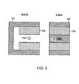
本明細書で用いられる「磁石」という用語は、周辺における少なくともある程度の体積空間に磁場を生成する、任意の材料または材料の任意の組合せを指す。一般的に、この磁石は永久磁石である。適切な材料には、NdFeB、FeCoなどが含まれるが、これらに限定されない。複数の磁石を用いて、新たな磁石、すなわち、磁石アレイを形成するように構成してもよい。この磁石アレイとして、例えば、C字形状ヨークを備えた永久磁石、ハルバッハ磁石(円筒形状やその他の形状)、U字形磁石、トロイド磁石(ドーナツ型磁石)などが挙げられる。 As used herein, the term “magnet” refers to any material or any combination of materials that generates a magnetic field in at least some volumetric space in the periphery. Generally, this magnet is a permanent magnet. Suitable materials include but are not limited to NdFeB, FeCo, and the like. A plurality of magnets may be used to form a new magnet, that is, a magnet array. Examples of the magnet array include a permanent magnet having a C-shaped yoke, a Halbach magnet (cylindrical shape and other shapes), a U-shaped magnet, a toroid magnet (donut-shaped magnet), and the like.
本発明にかかるシステムの磁石、磁石形態および磁場生成手段は、磁気が弱くてもよく、および/または不均一な磁場を生成してもよい。典型的には、本発明にかかる磁石および/または磁石形態が生成する最大の磁場強度は、約0.2テスラ(T)から約2テスラである。より典型的には、約0.3テスラから約1.5テスラである。さらに典型的には、約0.3テスラから約1.5テスラである。さらに典型的には、約0.4テスラから約1.1テスラである。さらに典型的には、約0.2テスラから約1.1テスラである。さらに典型的には、約0.2テスラから約0.8テスラである。最も典型的には、約0.45テスラから約0.85テスラである。ある実施態様において、前記磁場強度は約2テスラ未満である。別の実施態様では、前記磁場強度は約1.1テスラ未満である。さらに別の実施態様では、前記磁場強度は約0.8テスラ未満である。 The magnet, magnet configuration and magnetic field generating means of the system according to the present invention may be weakly magnetized and / or generate a non-uniform magnetic field. Typically, the maximum magnetic field strength produced by the magnets and / or magnet forms according to the present invention is from about 0.2 Tesla (T) to about 2 Tesla. More typically, it is about 0.3 Tesla to about 1.5 Tesla. More typically from about 0.3 Tesla to about 1.5 Tesla. More typically, it is about 0.4 Tesla to about 1.1 Tesla. More typically, it is about 0.2 Tesla to about 1.1 Tesla. More typically, it is about 0.2 Tesla to about 0.8 Tesla. Most typically, it is about 0.45 Tesla to about 0.85 Tesla. In certain embodiments, the magnetic field strength is less than about 2 Tesla. In another embodiment, the magnetic field strength is less than about 1.1 Tesla. In yet another embodiment, the magnetic field strength is less than about 0.8 Tesla.
本明細書で用いる「不均一な磁場」という用語は、分光法において必要とされる磁場よりも均一性の低い磁場に対する表現である。均一性は、測定対象となる空間によって変化する。本願の場合、磁場均一性は約10,000ppm〜約10ppmであってもよい。ある実施態様では、磁場均一性は約50ppm〜5,000ppmであってもよい。特定の実施態様では、磁場均一性は約100ppm〜約1,000ppmであってもよい。 As used herein, the term “inhomogeneous magnetic field” is a representation for a magnetic field that is less uniform than that required in spectroscopy. The uniformity varies depending on the space to be measured. For the present application, the magnetic field uniformity may be from about 10,000 ppm to about 10 ppm. In certain embodiments, the magnetic field uniformity may be between about 50 ppm and 5,000 ppm. In certain embodiments, the magnetic field uniformity may be from about 100 ppm to about 1,000 ppm.
また、一般的に、本発明にかかるシステムで用いる磁場は実質的に静磁場であり、すなわち、時間が経っても実質上変化しない。温度変動等による磁場の変化は、この「実質上」の変化に含めないものとする。 In general, the magnetic field used in the system according to the present invention is substantially a static magnetic field, that is, it does not substantially change over time. Changes in the magnetic field due to temperature fluctuations and the like are not included in this “substantially” change.
本発明にかかる小型のプローブヘッドは、生体磁気共鳴(インビボ(in-vivo)でのNMR)測定に用いることができるが、これに限定されない。哺乳動物の体内に完全に埋め込まれる小型のプローブヘッドの場合、そのプローブヘッドは、好ましくは、埋込みの侵襲性を軽減するために小型の磁石を備えている。典型的には、埋込み用の磁石は全方向の寸法が約2インチ(inch)(約5.08センチメートル)未満である。より典型的には、埋込み用の磁石は全方向の寸法が約1インチ(inch)(約2.54センチメートル)未満である。最も典型的には、埋込み用の磁石は全方向の寸法が約0.5インチ(inch)(約1.27センチメートル)未満である。 The small probe head according to the present invention can be used for biomagnetic resonance (in-vivo NMR) measurement, but is not limited thereto. In the case of a small probe head that is completely implanted in the body of the mammal, the probe head preferably includes a small magnet to reduce the invasiveness of the implantation. Typically, an embedding magnet has an omnidirectional dimension of less than about 2 inches (about 5.08 centimeters). More typically, embedded magnets have an omnidirectional dimension of less than about 1 inch (about 2.54 centimeters). Most typically, embedded magnets have dimensions less than about 0.5 inches (about 1.27 centimeters) in all directions.
本発明にかかるプローブヘッドは、インビトロ(生体外)(in-vitro)で用いられてもよく、例えば、小型および/または持ち運び型の磁気共鳴システムの一部として使用されてもよい。典型的には、このようなシステムに用いるプローブヘッドの磁石は全方向の寸法が約2インチ(inch)(約5.08センチメートル)未満である。より典型的には、前記磁石は全方向の寸法が約1インチ(約2.54センチメートル)未満である。最も典型的には、前記磁石は全方向の寸法が約0.5インチ(約1.27センチメートル)未満である。各方向の寸法は、互いの寸法とは無関係に決定されてもよい。 The probe head according to the present invention may be used in-vitro, for example, as part of a small and / or portable magnetic resonance system. Typically, the probe head magnets used in such systems have an omnidirectional dimension of less than about 2 inches (about 5.08 centimeters). More typically, the magnet has an omnidirectional dimension of less than about 1 inch (about 2.54 centimeters). Most typically, the magnet has an omnidirectional dimension of less than about 0.5 inch (about 1.27 centimeters). The dimensions in each direction may be determined independently of each other's dimensions.
本発明で用いる「磁場生成手段」という用語は、周辺における少なくともある程度の体積空間に磁場を生成する手段(装置)を指す。一般的に、磁場生成手段は電源を必要とし、電源が入った状態のときに、目標の磁場を生成する。磁場生成手段には、一例として、金属棒を備えた電磁石や金属棒を備えていない電磁石などが含まれるが、これらに限定されない(1994年の雑誌「Sensors and Actuators」に掲載されたCardotらの記事を参照のこと)。 The term “magnetic field generating means” used in the present invention refers to means (apparatus) for generating a magnetic field in at least some volume space around the periphery. In general, the magnetic field generating means requires a power source, and generates a target magnetic field when the power is on. Examples of magnetic field generating means include, but are not limited to, electromagnets with or without metal bars (Cardot et al. Published in the 1994 magazine “Sensors and Actuators”). See article).
磁場生成手段を用いるプローブヘッドは、哺乳動物の体内に埋め込み可能に構成することもできる。しかしながら、磁場生成手段は磁石よりも大型な場合が多く、かつ、磁石よりも複雑である(例えば、電源を必要とする)。したがって、より一般的には、磁場生成手段を用いる場合、プローブヘッドは、哺乳動物の体外で使い捨て使用される。 The probe head using the magnetic field generating means can be configured to be implantable in the body of a mammal. However, the magnetic field generating means is often larger than the magnet and more complicated than the magnet (for example, requires a power source). Therefore, more generally, when using the magnetic field generating means, the probe head is used disposable outside the body of the mammal.
本発明にかかるシステムの磁石または磁場生成手段は、磁気共鳴シグナルの測定を可能にする十分な磁場強度の磁場をサンプル領域において生成するように選択かつ位置決めされる。所与の体積空間(例えば、サンプル領域)における磁石または磁場生成手段の磁場強度は、当該技術分野で知られている方法を用いて算出および/または近似することができる。一般的に、磁場強度は、磁石または磁場生成手段の性質、およびサンプル領域に対する磁石または磁場生成手段の位置によって変化する。また、サンプル領域における磁石または磁場生成手段の磁場強度は、当該技術分野で知られている方法や装置(例えば、ガウスメータ、テスラメータ、ホール効果プローブなど)によって測定することができる。典型的には、サンプル領域内の磁場強度が約0.2テスラ(Tesla)から約2テスラの範囲内であれば、磁気共鳴シグナルを測定するのに十分である。より典型的には、サンプル領域内の磁場強度が約0.2テスラから約1テスラの範囲内であれば、磁気共鳴シグナルを測定するのに十分である。さらに典型的には、サンプル領域内の磁場強度が約0.2テスラから約0.8テスラの範囲内であれば、磁気共鳴シグナルを測定するのに十分である。最も典型的には、サンプル領域内の磁場強度が約0.3テスラから約0.65テスラの範囲内であれば、磁気共鳴シグナルを測定するのに十分である。 The magnet or magnetic field generating means of the system according to the invention is selected and positioned to generate a magnetic field of sufficient magnetic field strength in the sample region that allows measurement of the magnetic resonance signal. The magnetic field strength of the magnet or magnetic field generating means in a given volume space (eg sample region) can be calculated and / or approximated using methods known in the art. In general, the magnetic field strength varies depending on the nature of the magnet or magnetic field generating means and the position of the magnet or magnetic field generating means relative to the sample region. Further, the magnetic field strength of the magnet or the magnetic field generating means in the sample region can be measured by a method or apparatus known in the art (for example, a gauss meter, a tesla meter, a Hall effect probe, etc.). Typically, a magnetic field strength in the sample region in the range of about 0.2 Tesla to about 2 Tesla is sufficient to measure the magnetic resonance signal. More typically, a magnetic field strength in the sample region in the range of about 0.2 Tesla to about 1 Tesla is sufficient to measure the magnetic resonance signal. More typically, a magnetic field strength in the sample region in the range of about 0.2 Tesla to about 0.8 Tesla is sufficient to measure the magnetic resonance signal. Most typically, a magnetic field strength in the sample region in the range of about 0.3 Tesla to about 0.65 Tesla is sufficient to measure the magnetic resonance signal.
本発明にかかるプローブヘッドに適した磁石および磁場生成手段は、特定の寸法に限定されない。しかしながら、特に、埋め込み可能な携帯用(手持ち式)のプローブヘッドについては、小型の磁石が望ましい。典型的には、本発明にかかるプローブヘッドの少なくとも1つの磁石または磁場生成手段の各々について、その全方向の寸法は約2インチ(約5.08センチメートル)未満である。より典型的には、前記少なくとも1つの磁石または磁場生成手段の各々について、その全方向の寸法は約1インチ(約2.54センチメートル)未満である。最も典型的には、前記少なくとも1つの磁石または磁場生成手段の各々について、その全方向の寸法は約0.5インチ(約1.27センチメートル)未満である。 Magnets and magnetic field generating means suitable for the probe head according to the present invention are not limited to specific dimensions. However, in particular for portable (hand-held) probe heads that can be implanted, small magnets are desirable. Typically, for each of the at least one magnet or magnetic field generating means of the probe head according to the invention, its omnidirectional dimension is less than about 2 inches (about 5.08 centimeters). More typically, for each of the at least one magnet or magnetic field generating means, its omnidirectional dimension is less than about 1 inch (about 2.54 centimeters). Most typically, for each of the at least one magnet or magnetic field generating means, its omni-directional dimension is less than about 0.5 inches (about 1.27 centimeters).
本発明にかかるプローブヘッドは、磁気共鳴システムの一部として磁気共鳴シグナルを検知/測定するにあたり、そのプローブヘッドの中に(詳細には、1つ以上のサンプル領域内に)検知用試薬(検知剤)を収容するものであってもよい。 The probe head according to the present invention has a detection reagent (detection) in the probe head (specifically, in one or more sample regions) for detecting / measuring a magnetic resonance signal as part of the magnetic resonance system. (Agent) may be accommodated.
本明細書で用いる「検知剤」という用語は、サンプル特性を検知するか、サンプル特性に反応(応答)するか、またはサンプル特性に影響される物質であって、これにより、サンプル特性の存在および/または程度を、そのサンプルに関連する磁気共鳴シグナルの存在、変化または大きさと相関させる(結び付ける)物質のことを指す。本明細書で用いる「サンプル特性」という用語は、所与のサンプルにおける任意の化学的特性および/または物理的特性を指す。適切なサンプル特性として、分析物の濃度(すなわち、サンプルに含まれるターゲットの分子、イオンやラジカル)、pH値、イオン強度、含水状態(例えば、組織や生体液の含水状態、すなわち、組織や生体液に含まれる水の濃度)、温度などが挙げられるが、これらに限定されない。 As used herein, the term “detecting agent” refers to a substance that senses, reacts to, or is affected by a sample characteristic, thereby determining the presence of the sample characteristic and Refers to a substance that correlates (or associates) a degree with / or the presence, change or magnitude of a magnetic resonance signal associated with the sample. As used herein, the term “sample property” refers to any chemical and / or physical property in a given sample. Appropriate sample characteristics include analyte concentration (ie, target molecules, ions and radicals contained in the sample), pH value, ionic strength, and moisture content (eg, moisture content of tissues and biological fluids, ie, tissue and biological conditions). Examples include, but are not limited to, the concentration of water contained in body fluid), temperature, and the like.
適切な検知剤として、乾燥試薬組成物、磁性粒子、応答性ポリマー、磁気共鳴造影剤などが挙げられるが、これらに限定されない。 Suitable detection agents include, but are not limited to, dry reagent compositions, magnetic particles, responsive polymers, magnetic resonance contrast agents, and the like.
適切な乾燥試薬組成物には、例えば、ビオチン被覆乾燥ナノ粒子(biotinylated coated nanoparticle)(T.J. LoweryらのAnal. Chem. (2008), 80, 1118-1123を参照されたい)が含まれるが、これに限定されない。ビオチン被覆乾燥ナノ粒子は、例えば、0.083mMのFe液、10mMのリン酸緩衝生理食塩水、および20mg/mlのデキストランで構成されるpH7.4の216μLのナノ粒子組成物として配合され得る。乾燥試薬組成物は、磁性粒子溶液(例えば、ビオチン被覆ナノ粒子溶液)を容器(例えば、ガラス製チューブ)に入れて、この容器を凍結乾燥装置(例えば、米国ニューヨーク州ガーディナーのVirTis社製の凍結乾燥装置)で凍結乾燥させる(例えば、−80℃で24時間)ことによって調製できる。この乾燥試薬組成物をサンプル用容器の分離領域内に充填する際には、その1つ以上の各分離領域に対し、凍結時に使用した容器から当該乾燥試薬組成物を移しかえるようにしてもよい。 Suitable dry reagent compositions include, for example, biotinylated coated nanoparticles (see TJ Lowery et al., Anal. Chem. (2008), 80, 1118-1123). It is not limited to. Biotin-coated dry nanoparticles can be formulated, for example, as a 216 μL nanoparticle composition at pH 7.4 composed of 0.083 mM Fe solution, 10 mM phosphate buffered saline, and 20 mg / ml dextran. In the dry reagent composition, a magnetic particle solution (for example, a biotin-coated nanoparticle solution) is placed in a container (for example, a glass tube), and the container is freeze-dried (for example, manufactured by VirTis, Gardiner, NY, USA). It can be prepared by lyophilization (for example, at −80 ° C. for 24 hours). When filling the dry reagent composition into the separation region of the sample container, the dry reagent composition may be transferred from the container used at the time of freezing to each of the one or more separation regions. .
本発明で用いる「磁性粒子」という用語は、サンプル特性に反応(応答)するか、またはサンプル特性に影響される粒子であって、これにより、サンプル特性の存在および/または程度を、そのサンプルに関連する磁気共鳴シグナルの存在、変化または大きさと相関させる(結び付ける)粒子のことを指す。一般的に、磁性粒子は凝集することで応答する。また、典型的には、磁性粒子の平均粒径は1nm(ナノメートル)〜5μm(マイクロメートル)程度である。磁性粒子は、常磁性または超常磁性を有するものであってもよい。磁性粒子は、その表面に結合部位を有していてもよい。好ましくは、前記結合部位は、分析物の存在またはその濃度に応じて、磁性粒子の凝集度を変化させるものである。磁性粒子は、Fe、Si、Sn、An、Ti、Bi、ZrおよびZnのうちの少なくとも1つの酸化物および/または水酸化物を含んでいてもよい。好ましくは、磁性粒子は、超常磁性であり、かつ、約1nm〜約100nmの結晶子サイズを有している。ナノスケールの磁性粒子(磁性ナノ粒子)は、好ましくは、金属酸化物のコアを有しており、かつ、コアの直径が、約1nm〜約25nm、約3nm〜約10nm、または約5nmである。前記結合部位は、次の1つ以上の種類、例えば、アミノ酸、核酸、オリゴヌクレオチド、治療剤、治療剤の代謝産物、ペプチド、ポリペプチド、タンパク質、炭水化物、多糖体、ウイルス、および細菌、に結合し得る。例えば、一実施態様において、前記結合部位は、1種、2種、またはそれ以上の種類のオリゴヌクレオチドおよび/または1種、2種またはそれ以上の種類のタンパク質に結合し得る。前記結合部位を有しているのは、1つ以上の磁性粒子と結合しているか、もしくは1つ以上の磁性粒子に関連付けられた(つまり、磁性粒子に対して親和性を示している)ポリマーまたはポリマーの一部であってもよい。好ましくは、前記結合部位は官能性基を含んでおり、例えば、前記結合部位は、次の1つ以上の種類、例えば、アミノ基、カルボキシ基、スルフヒドリル基、アミン基、イミン基、エポキシ基、ヒドロキシ基、チオール基、アクリレート基、およびイソシアノ基、を含んでいてもよい。 As used herein, the term “magnetic particle” is a particle that responds (responds) to or is influenced by sample properties, thereby indicating the presence and / or extent of sample properties to the sample. Refers to a particle that correlates (associates) with the presence, change or magnitude of an associated magnetic resonance signal. In general, magnetic particles respond by aggregating. Further, typically, the average particle size of the magnetic particles is about 1 nm (nanometer) to 5 μm (micrometer). The magnetic particles may be paramagnetic or superparamagnetic. The magnetic particle may have a binding site on its surface. Preferably, the binding site changes the degree of aggregation of the magnetic particles depending on the presence or concentration of the analyte. The magnetic particles may contain at least one oxide and / or hydroxide of Fe, Si, Sn, An, Ti, Bi, Zr and Zn. Preferably, the magnetic particles are superparamagnetic and have a crystallite size of about 1 nm to about 100 nm. The nanoscale magnetic particles (magnetic nanoparticles) preferably have a metal oxide core and the core diameter is from about 1 nm to about 25 nm, from about 3 nm to about 10 nm, or about 5 nm. . The binding site binds to one or more of the following types, such as amino acids, nucleic acids, oligonucleotides, therapeutic agents, therapeutic metabolites, peptides, polypeptides, proteins, carbohydrates, polysaccharides, viruses, and bacteria. Can do. For example, in one embodiment, the binding site may bind to one, two or more types of oligonucleotides and / or one, two or more types of proteins. The binding site has a polymer that is bound to or associated with one or more magnetic particles (ie, exhibits affinity for the magnetic particles) Or it may be a part of the polymer. Preferably, the binding site comprises a functional group, for example, the binding site is one or more of the following types, for example, an amino group, a carboxy group, a sulfhydryl group, an amine group, an imine group, an epoxy group, A hydroxy group, a thiol group, an acrylate group, and an isocyano group may be included.
分析物は、タンパク質、ペプチド、ポリペプチド、アミノ酸、核酸、オリゴヌクレオチド、治療剤、治療剤の代謝産物、RNA、DNA、抗体、生物、ウイルス、細菌、炭水化物、多糖体、およびグルコースからなる群の一種以上を含んでいてもよい。分析物は、また、例えば、脂質、気体(例えば、酸素、二酸化炭素など)、電解質(例えば、ナトリウム、カリウム、塩化物、重炭酸塩、血中尿素窒素(BUN)、クレアチニン、グルコース、マグネシウム、リン酸塩、リン酸エステル、カルシウム、アンモニア、乳酸塩、乳酸エステル)、リポタンパク質、コレステロール、脂肪酸、糖タンパク質、プロテオグリカン、およびリポ多糖体からなる群の一種以上を含んでいてもよい。 The analyte is a protein, peptide, polypeptide, amino acid, nucleic acid, oligonucleotide, therapeutic agent, therapeutic metabolite, RNA, DNA, antibody, organism, virus, bacteria, carbohydrate, polysaccharide, and glucose One or more types may be included. Analytes can also include, for example, lipids, gases (eg, oxygen, carbon dioxide, etc.), electrolytes (eg, sodium, potassium, chloride, bicarbonate, blood urea nitrogen (BUN), creatinine, glucose, magnesium, (Phosphate, phosphate, calcium, ammonia, lactate, lactate), lipoprotein, cholesterol, fatty acid, glycoprotein, proteoglycan, and lipopolysaccharide may be included.
例えば、磁性粒子は、糖化ヘモグロビンに応答するものとされる。例えば、アミノCLIOナノ粒子(すなわち、アミノ基修飾された架橋デキストランで被覆された酸化鉄ナノ粒子)を、一般的な液相化学下でボロン酸化合物で修飾したものであってもよい。ボロン酸化合物(例えば、ボロン酸、フェニルボロン酸、ボロン酸、ボロネート(ボロン酸塩およびボロン酸エステル)など)は、HbA1cと称される、他の種類の糖化ヘモグロビンとの違いに基づいて命名された特定の種類の糖化ヘモグロビンに対して親和性を有する。ヘモグロビンは、4つのサブユニット、すなわち、2本のα鎖と2本のβ鎖で構成されており、HbA1cは2箇所の結合部位を有する。これにより、HbA1cは、ボロン酸修飾された超常磁性酸化鉄粒子の凝集を促進する。ボロン酸化合物は、ヘモグロビンに結合したグルコースのシス−ジオール部位を介してサンプル中のHbA1cと反応し、五員環構造を形成する。ボロネート基は、様々な化学的性質により、固相体と共有結合し得るか、または固相体に静電的に結び付き得る。アミノCLIOナノ粒子などの固相体は、一般的な液相化学反応を用いてボロン酸化合物で修飾することができる。アミノCLIOナノ粒子は、アミノ基修飾された架橋デキストランで被覆された酸化鉄ナノ粒子である。デキストランポリマー被覆が付与する可溶性によって、このナノ粒子の液相化学反応が可能となる。適切なボロン酸化合物には、4−カルボキシフェニルボロン酸、3−ニトロ−5−カルボキシフェニルボロン酸、m−アミノフェニルボロン酸(APBA)が含まれるが、これらに限定されない。 For example, the magnetic particles are supposed to respond to glycated hemoglobin. For example, amino CLIO nanoparticles (that is, iron oxide nanoparticles coated with amino group-modified crosslinked dextran) may be modified with a boronic acid compound under general liquid phase chemistry. Boronic acid compounds (eg, boronic acid, phenylboronic acid, boronic acid, boronates (boronates and boronic esters), etc.) are named based on differences from other types of glycated hemoglobin, referred to as HbA1c. It has affinity for certain types of glycated hemoglobin. Hemoglobin is composed of four subunits, that is, two α chains and two β chains, and HbA1c has two binding sites. Thereby, HbA1c promotes aggregation of superparamagnetic iron oxide particles modified with boronic acid. The boronic acid compound reacts with HbA1c in the sample via a cis-diol site of glucose bound to hemoglobin to form a five-membered ring structure. The boronate group can be covalently linked to the solid phase or electrostatically attached to the solid phase, due to various chemical properties. Solid phase bodies such as amino CLIO nanoparticles can be modified with boronic acid compounds using common liquid phase chemical reactions. Amino CLIO nanoparticles are iron oxide nanoparticles coated with amino group-modified cross-linked dextran. The solubility imparted by the dextran polymer coating allows a liquid phase chemical reaction of the nanoparticles. Suitable boronic acid compounds include, but are not limited to, 4-carboxyphenylboronic acid, 3-nitro-5-carboxyphenylboronic acid, m-aminophenylboronic acid (APBA).
本明細書で用いる「ナノセンサ」という用語は、常磁性の粒子または超常磁性の粒子であって、一般的には、ナノメートルスケールの粒子であり、磁性のコアとその周囲のポリマーマトリクス層とで構成されるか、かつ/または標的化合物もしくは分析物に対する結合部位または親和性基を、誘導体としてまたは官能基として有している。適切なナノセンサには、応答性ポリマーで被覆された磁性ナノ粒子が含まれる。これらナノセンサは、磁性ナノ粒子の能力を利用して、核磁気共鳴(NMR)で検出可能な核スピン(以降、その一例である「水分子の水素原子」を代表例として用いる)をディフェーズして、ナノ粒子の凝集を利用せずに検出を行う。各ナノ粒子のポリマーマトリクス層は、検出対象の分析物および/または条件に曝されると膨張または収縮する。この結果生じるナノ粒子の粒径の変化は、ナノ粒子の近傍で自由拡散する水分子のディフェーズに影響を及ぼし、これにより、核磁気共鳴(NMR)で検出可能な1つ以上の特性に影響を与える。公知の基準サンプルを用いて、核磁気共鳴(NMR)で検出される特性を較正することにより、本発明にかかるプローブヘッドを用いた核磁気共鳴(NMR)法で、検出対象の条件および/または分析物が試験サンプル中に存在するか否かを検出することができる。 As used herein, the term “nanosensor” is a paramagnetic particle or a superparamagnetic particle, generally a nanometer-scale particle, comprising a magnetic core and a surrounding polymer matrix layer. It is configured and / or has a binding site or affinity group for the target compound or analyte as a derivative or as a functional group. Suitable nanosensors include magnetic nanoparticles coated with a responsive polymer. These nanosensors use the capability of magnetic nanoparticles to dephase nuclear spins that can be detected by nuclear magnetic resonance (NMR) (hereinafter, the “hydrogen atom of water molecule” as an example). Thus, detection is performed without using aggregation of nanoparticles. The polymer matrix layer of each nanoparticle expands or contracts when exposed to the analyte and / or conditions to be detected. The resulting change in nanoparticle size affects the dephasing of water molecules that freely diffuse in the vicinity of the nanoparticle, thereby affecting one or more properties that can be detected by nuclear magnetic resonance (NMR). give. By calibrating the characteristics detected by nuclear magnetic resonance (NMR) using a known reference sample, in the nuclear magnetic resonance (NMR) method using the probe head according to the present invention, the conditions to be detected and / or It can be detected whether the analyte is present in the test sample.
検出対象の核が水分子の水素原子である場合、好ましくは、前記ポリマーマトリクスは、ポリマーの「メッシュ」を備えた刺激応答性ヒドロゲルまたは分子応答性ヒドロゲルの形態を取る。この「メッシュ」は結合部位によって架橋結合しているので、対象の分析物の物理的もしくは化学的刺激または物理的パラメータの変化に応じて、ポリマーマトリクスの体積、透過性および水素原子含有量が変化する。これは、ポリマーマトリクスを、親水性のポリマーネットワーク(ポリマー網目構造体)として構成することによって実現できる。この親水性のポリマーネットワークは、結合部位をペンダント基またはポリマー主鎖の一部として含んでおり、その結合部位は、分析物の成分と1つ以上の共有結合もしくは水素結合を形成するか、分析物の成分とのファンデルワールス相互作用によるか、または分析物の成分との物理的絡み合いにより、水の透過性(および/または環境中の他の分子の透過性)に変化を引き起こす。分析物の存在によってポリマーの架橋密度に変化が生じ、これが溶液中のポリマーの体積分率(体積パーセント)を変化させる。架橋密度の変化は、さらに、ナノ粒子の粒径を変化させ、これにより、ナノ粒子の拡散時間が変化する。以下の比例関係式から分かるように、拡散時間および比体積は、溶液について測定されるT2緩和度(1/T2)と比例する。 Where the nuclei to be detected are hydrogen atoms of water molecules, preferably the polymer matrix takes the form of a stimulus responsive hydrogel or a molecule responsive hydrogel with a polymer “mesh”. Because this “mesh” is cross-linked by binding sites, the volume, permeability and hydrogen atom content of the polymer matrix change in response to physical or chemical stimuli or changes in physical parameters of the analyte of interest. To do. This can be realized by configuring the polymer matrix as a hydrophilic polymer network (polymer network structure). This hydrophilic polymer network contains a binding site as a pendant group or part of the polymer backbone, and the binding site forms one or more covalent or hydrogen bonds with the analyte components or analyzes Changes in water permeability (and / or permeability of other molecules in the environment) are caused by van der Waals interactions with the constituents of the substance or by physical entanglement with the constituents of the analyte. The presence of the analyte causes a change in the crosslink density of the polymer, which changes the volume fraction (volume percent) of the polymer in solution. The change in crosslink density further changes the particle size of the nanoparticles, thereby changing the diffusion time of the nanoparticles. As can be seen from the proportional relationship below, the diffusion time and specific volume are proportional to the T 2 relaxation (1 / T 2 ) measured for the solution.
![]()
![]()
式中、Vpは溶液中の粒子の比体積であり、Rは粒子半径であり、Dは水の拡散定数である。R2/Dは拡散時間τdに等しい。水の拡散時間とは、ある粒子を超える場所まで水分子が拡散するのに必要な時間のことを指し、発生するT2緩和の大きさに比例する。 Where Vp is the specific volume of particles in the solution, R is the particle radius, and D is the diffusion constant of water. R 2 / D is equal to the diffusion time τ d . Water diffusion time refers to the time required for water molecules to diffuse beyond a certain particle, and is proportional to the amount of T 2 relaxation that occurs.
前記結合部位は、次の1つ以上の種類:ケミカルバインダ(化学結合剤)、電気活性メディエータ、電子対供与体および電子対受容体、であってもよい。結合部位は、アミノ基、カルボキシ基、スルフヒドリル基、アミン基、イミン基、エポキシ基、ヒドロキシ基、チオール基、アクリレート基およびイソシアノ基のうち少なくとも1種以上であってもよい。例えば、結合部位は、pHを検知する酢酸部分(例えば、ポリ(アクリル酸)における酢酸部分)、またはジオールの存在(例えば、グルコースのジオール部分)を検知するフェニルボロン酸であってもよい。あるいは、結合部位は、結合対(binding pair)または結合性ペンダント(binding pendant)であり、例えば、同種抗原の存在下でクロスリンカーとして作用する抗体、または同種抗体の存在下でクロスリンカーとして作用する抗原などが挙げられ、これらは競合的なアフィニティ(親和性)反応により、マトリクスに出入りする水分子の水素原子の量および比体積の変化を調節する。これは、一般的に、分析対象の物理的パラメータの変化に応じてマトリクスポリマーの架橋度が調節されることで、水の透過性(磁性粒子近傍のマトリクスに出入りする水およびマトリクス領域内における水の並進拡散の量および速度を含む)が制御されることにより行われる。例えば、結合対は、低親和性リガンドに結合したリガンド結合タンパク質(例えば、炭水化物に結合したコンカナバリンA)であってもよい。この系にグルコースを投入することにより、低親和性リガンドがグルコースに置換され、マトリクスの架橋が変化する。別の例として、マトリクス固定化抗原またはマトリクス固定化標的と結合することでマトリクスを架橋する、マトリクス固定化抗体、マトリクス固定化抗体断片またはマトリクス固定化ペプチドが挙げられる。この結合よりも親和性の高い分析物の存在により、その架橋マトリクスが乱され、マトリクスの膨張が生じる。 The binding site may be one or more of the following types: chemical binders, electroactive mediators, electron pair donors and electron pair acceptors. The binding site may be at least one of amino group, carboxy group, sulfhydryl group, amine group, imine group, epoxy group, hydroxy group, thiol group, acrylate group and isocyano group. For example, the binding site may be an acetic acid moiety that senses pH (eg, an acetic acid moiety in poly (acrylic acid)) or a phenylboronic acid that senses the presence of a diol (eg, the diol moiety of glucose). Alternatively, the binding site is a binding pair or binding pendant, eg, an antibody that acts as a crosslinker in the presence of a cognate antigen, or a crosslinker in the presence of a cognate antibody. Antigens and the like, which regulate changes in the amount of hydrogen atoms and specific volume of water molecules entering and leaving the matrix by a competitive affinity reaction. In general, the degree of cross-linking of the matrix polymer is adjusted in accordance with changes in the physical parameters to be analyzed, so that water permeability (water entering and exiting the matrix in the vicinity of the magnetic particles and water in the matrix region) is adjusted. (Including the amount and speed of translational diffusion). For example, the binding pair may be a ligand binding protein bound to a low affinity ligand (eg, concanavalin A bound to a carbohydrate). By introducing glucose into this system, the low affinity ligand is replaced by glucose and the cross-linking of the matrix changes. Another example is a matrix-immobilized antibody, matrix-immobilized antibody fragment or matrix-immobilized peptide that crosslinks the matrix by binding to a matrix-immobilized antigen or matrix-immobilized target. The presence of analytes with higher affinity than this binding disrupts the cross-linked matrix and causes matrix expansion.
上記のような応答性を有するマトリクスは、1種以上のモノマーおよび/またはポリマーを含む材質のマトリクスであってもよい。この1種以上のモノマーおよび/またはポリマーの官能基は、前記結合部位をナノ粒子に結び付けるか、または前記結合部位とナノ粒子とを安定な親和性状態に保持することによって(可逆的な)複合体を形成させる。前記ポリマーとして、天然ポリマー、合成ポリマー、天然ポリマーと合成ポリマーの組合せ、形状記憶ポリマー、ブロックコポリマー(PEO(ポリエチレンオキシド)、PPO(ポリプロピレンオキシド))、またはこれら各種類の誘導体が挙げられる。例えば、前記マトリクスポリマーとして、ポリ(N−イソプロピルアクリルアミド)が挙げられる。前記マトリクスポリマーは、例えば、他にも、ポリ(N−イソプロピルアクリルアミド)(PNIAAm)、ポリ(N,N−ジエチルアクリルアミド)(PDEAAm)、ポリ(N−イソプロピルアクリルアミド−ブチルメタクリレート)コポリマー(P(NIAAm−co−BMA))、PEO−PPO−PEO(例えば、プルロニック(登録商標))、N,N−ジエチルアミノエチルメタクリレート(DEA)、2−ヒドロキシプロピルメタクリレート(HPMA)、ポリ−(メタクリル酸−エチレングリコール)グラフトコポリマー、ポリ(2−グルコシルオキシエチルメタクリレート)、ポリ(N−ビニル−2−ピロリドン−3(アクリルアミド)フェニルボロン酸)コポリマー、およびN−(S)−sec−ブチルアクリルアミドからなる群のうちの少なくとも1種以上であってもよい(あるいは、前記マトリクスポリマーは、この群のうちの少なくとも1種以上を含むものであってもよい)。前記官能基は、適切な化学官能基であれば何でもよく、例えば、カルボキシ基、アミノ基やスルフヒドリル基などである。また、1種以上の特定の部位は、前記官能基との(可逆的な)複合体化によって、物理的吸着および/もしくは水素結合によって、またはファンデルワールス相互作用によって、ナノ粒子に対して取り付けられてもよい。上記のような応答性を有するポリマー(応答性ポリマー)からなるマトリクスは、物理的刺激および/または化学的刺激を受けることによって、ポリマー層の比体積に影響を及ぼし、核磁気共鳴(NMR)測定可能な特性(例えば、T2緩和度)の検出可能な変化を引き起こす。 The matrix having responsiveness as described above may be a matrix made of a material including one or more monomers and / or polymers. The functional group of the one or more monomers and / or polymers can be combined (reversible) by linking the binding site to the nanoparticle or holding the binding site and the nanoparticle in a stable affinity state. Form the body. Examples of the polymer include a natural polymer, a synthetic polymer, a combination of a natural polymer and a synthetic polymer, a shape memory polymer, a block copolymer (PEO (polyethylene oxide), PPO (polypropylene oxide)), or a derivative of each of these types. For example, poly (N-isopropylacrylamide) is mentioned as the matrix polymer. Other examples of the matrix polymer include poly (N-isopropylacrylamide) (PNIAAm), poly (N, N-diethylacrylamide) (PDEAAm), and poly (N-isopropylacrylamide-butyl methacrylate) copolymer (P (NIAAm). -Co-BMA)), PEO-PPO-PEO (for example, Pluronic (registered trademark)), N, N-diethylaminoethyl methacrylate (DEA), 2-hydroxypropyl methacrylate (HPMA), poly- (methacrylic acid-ethylene glycol) ) Graft copolymers, poly (2-glucosyloxyethyl methacrylate), poly (N-vinyl-2-pyrrolidone-3 (acrylamide) phenylboronic acid) copolymers, and N- (S) -sec-butylacrylamide May be at least one or more of the Ranaru group (or said matrix polymer may include at least one or more of the group). The functional group may be any suitable chemical functional group, such as a carboxy group, an amino group, or a sulfhydryl group. One or more specific sites may also be attached to the nanoparticles by (reversible) complexation with the functional groups, by physical adsorption and / or hydrogen bonding, or by van der Waals interactions. May be. A matrix composed of a polymer having a response as described above (responsive polymer) affects the specific volume of the polymer layer by receiving physical and / or chemical stimulation, and nuclear magnetic resonance (NMR) measurement. Causes a detectable change in a possible property (eg, T 2 relaxation).
「応答性ポリマー」(本明細書において「スマートポリマー」とも称す)という用語は、例えば、pH、イオン強度、特定の分析物(分子や生体分子)などに対する感受性が高いポリマーのことを指す。応答性ポリマーの場合、サンプル(例えば、生体液)中の変化に応じて、ポリマーの水和レベル、架橋密度や他の特性などが変化する。ポリマーの状態が変化することにより、埋め込まれたRFコイルによって検出可能な磁気共鳴シグナルにも変化が生じる。適切なスマートポリマーは、例えば、Gemeinhart, RA, Chen J, Park, H, Park, Kによる2000年の「高速応答性を有する超多孔質ヒドロゲルのpH感度」J. Biomater. Sci. Polym. Ed.11: 1371-1380;Murakami Y, Maeda, Mによる2005年の「収縮/膨張可能なDNA応答性ヒドロゲル」Biomacromolecules, 6: 2927-2929;Miyata, T, Uragami, T, Nakamae, Kらによる2002年の「生体分子応答性ヒドロゲル」Adv Drug Deliv Rev, 54: 79-98;Zhang, R, Bowyer, A, Eisenthal, R, Hubble, Jらによる2006年の「抗原応答性ヒドロゲルに基づくスマート膜」Biotechnol Bioeng;などに記載されており、当該技術分野で知られている。 The term “responsive polymer” (also referred to herein as “smart polymer”) refers to a polymer that is highly sensitive to, for example, pH, ionic strength, specific analytes (molecules and biomolecules), and the like. In the case of a responsive polymer, the hydration level, crosslink density, and other characteristics of the polymer change in response to changes in the sample (eg, biological fluid). Changing the state of the polymer also changes the magnetic resonance signal detectable by the embedded RF coil. Suitable smart polymers are described, for example, by Gemeinhart, RA, Chen J, Park, H, Park, K, 2000, “pH Sensitivity of Superporous Hydrogels with Fast Response”, J. Biomater. Sci. Polym. Ed. 11: 1371-1380; 2005 “Shrinkable / swellable DNA-responsive hydrogel” by Murakami Y, Maeda, M. Biomacromolecules, 6: 2927-2929; 2002 by Miyata, T, Uragami, T, Nakamae, K et al. “Biomolecule-responsive hydrogels” by Adv Drug Deliv Rev, 54: 79-98; Zhang, R, Bowyer, A, Eisenthal, R, Hubble, J et al. 2006 “Smart membranes based on antigen-responsive hydrogels” Biotechnol Bioeng; and the like and are known in the art.
本発明にかかるプローブヘッドは、RFコイルを備えている。 The probe head according to the present invention includes an RF coil.
本明細書で用いる「RFコイル」という用語は、磁気共鳴システムの一部であるプローブヘッドを用いた分析時に、対応する検出領域における磁気共鳴シグナルを感知および/または検出するのに適したコイルであって、任意で、さらに、分析対象のサンプルに対し、対応する長さのRFパルスを適用(印加)および/または発生することのできるコイルを指す。適切なRFコイルの種類には、平面コイルおよび「立体型(whole volume)」コイルが含まれ、この「立体型」コイルとして、対向式サドルコイル、ソレノイドコイル、ヘルムホルツコイルなどが挙げられる。一般的には、本発明にかかるシステムで用いられるプローブヘッドは、ソレノイドコイルを備える。 As used herein, the term “RF coil” is a coil suitable for sensing and / or detecting magnetic resonance signals in a corresponding detection region during analysis using a probe head that is part of a magnetic resonance system. And optionally further refers to a coil capable of applying (applying) and / or generating a corresponding length of RF pulses to the sample to be analyzed. Suitable types of RF coils include planar coils and “whole volume” coils, which include opposed saddle coils, solenoid coils, Helmholtz coils, and the like. Generally, the probe head used in the system according to the present invention comprises a solenoid coil.
本明細書で用いる「検出領域」という用語は、所与の磁気共鳴システムの一部である所与のRFコイルに関連した体積空間であって、そのRFコイルによって磁気共鳴シグナルを原則的に検出することができる体積空間を指す。本明細書で用いる「検出可能」または「検出することができる」という用語は、バックグラウンドのノイズレベルから識別可能または識別することができる、という意味を指し、すなわち、所与の磁気共鳴システムの一部である所与のRFコイルにより、バックグラウンドのノイズレベルからシグナルを識別できた場合、磁気共鳴シグナルを「検出可能」または「検出することができる」といえる。所与のRFコイル−磁気共鳴システムの組合せにおける検出領域は、当該技術分野で知られている方法を用いて算出および/または近似および/または測定することができる。しかしながら、一般的には、検出領域を近似すれば十分である。例えば、ソレノイドコイルの場合、一般的に、検出領域は実質上コイルで取り囲まれた領域であり、典型的には、この領域は略円筒形状である。ある実施態様において、RFコイルは円筒形状である。つまり、ソレノイドコイルの場合、検出領域のだいたいの近似は、閉じた円筒形状の体積空間であり、極めて簡単に計算することができる。他の種類のRFコイルについても、同様の近似計算手法が当該技術分野で知られている(例えば、Mispelter, J., Lupu, M., Briquet, A.の「生物物理学実験および生物医学実験用のNMRプローブヘッド」2006 Imperial College Press, Londonを参照されたい)。別の実施態様では、RFコイルは、略円筒形状のコイル領域を取り囲むように巻かれており、かつ、その対応する検出領域は、実質上、この円筒形状の領域である。さらに別の実施態様では、RFコイルは、そのコイル領域が励起可能領域の約80パーセントから約100パーセントに相当するように位置決めされている。さらに別の実施態様では、RFコイルは、そのコイル領域が励起可能領域の実質上全体に相当するように位置決めされている。 As used herein, the term “detection region” is the volume space associated with a given RF coil that is part of a given magnetic resonance system, by which the magnetic resonance signal is principally detected. Refers to the volume space that can be. As used herein, the term “detectable” or “can be detected” refers to the meaning that it is distinguishable or distinguishable from background noise levels, ie, for a given magnetic resonance system. A given RF coil that is part can be said to be “detectable” or “detectable” if the signal can be distinguished from the background noise level. The detection region in a given RF coil-magnetic resonance system combination can be calculated and / or approximated and / or measured using methods known in the art. However, in general, it is sufficient to approximate the detection area. For example, in the case of a solenoid coil, the detection region is generally a region substantially surrounded by the coil, and typically this region is substantially cylindrical. In certain embodiments, the RF coil is cylindrical. That is, in the case of a solenoid coil, the approximate approximation of the detection region is a closed cylindrical volume space, which can be calculated very easily. Similar approximation methods are known in the art for other types of RF coils (see, for example, Biophysics and Biomedical Experiments by Mispelter, J., Lupu, M., Briquet, A. (See 2006 Imperial College Press, London). In another embodiment, the RF coil is wound to surround a generally cylindrical coil region, and its corresponding detection region is substantially this cylindrical region. In yet another embodiment, the RF coil is positioned such that its coil area represents from about 80 percent to about 100 percent of the excitable region. In yet another embodiment, the RF coil is positioned such that its coil area represents substantially the entire excitable area.
本明細書で用いる「感受領域」という用語は、励起可能領域と検出領域との重複する領域であって、RFコイルを用いて磁気共鳴シグナルを検出することができる領域のことを指す。感受領域は、充填率(例えば、RFコイルの検出領域がサンプル領域内を占める割合)によって決まる。 As used herein, the term “sensitive region” refers to a region in which an excitable region and a detection region overlap, and a magnetic resonance signal can be detected using an RF coil. The sensitive area is determined by the filling rate (for example, the ratio of the detection area of the RF coil in the sample area).
ある実施態様では、充填率は約10パーセントから約100パーセントである。別の実施態様では、充填率は約50パーセントから約100パーセントである。さらに別の実施態様では、充填率は約80パーセントである。さらに別の実施態様では、充填率は実質上100パーセントである。さらに別の実施態様では、充填率は、少なくとも約0.1、少なくとも約0.5、少なくとも約0.75、少なくとも約0.9、または約1である。 In some embodiments, the fill factor is from about 10 percent to about 100 percent. In another embodiment, the fill factor is from about 50 percent to about 100 percent. In yet another embodiment, the fill factor is about 80 percent. In yet another embodiment, the fill factor is substantially 100 percent. In yet another embodiment, the fill factor is at least about 0.1, at least about 0.5, at least about 0.75, at least about 0.9, or about 1.
典型的には、検出領域は励起可能領域の約10パーセントから約100パーセントに相当する。より典型的には、プローブヘッド内の所与のRFコイルの検出領域は、励起可能領域の約50パーセントから約100パーセントに相当する。さらに典型的には、検出領域は励起可能領域の約80パーセントに相当する。最も典型的には、検出領域は励起可能領域の実質上全体に相当する。 Typically, the detection region represents about 10 percent to about 100 percent of the excitable region. More typically, the detection area of a given RF coil in the probe head represents about 50 percent to about 100 percent of the excitable region. More typically, the detection region represents about 80 percent of the excitable region. Most typically, the detection region represents substantially the entire excitable region.
また、典型的には、励起可能領域は検出領域の約10パーセントから約100パーセントに相当する。より典型的には、励起可能領域は検出領域の約50パーセントから約100パーセントに相当する。さらに典型的には、励起可能領域は検出領域の約80パーセントから約100パーセントに相当する。最も典型的には、励起可能領域は検出領域の実質上全体に相当する。 Also, typically, the excitable region corresponds to about 10 percent to about 100 percent of the detection region. More typically, the excitable region corresponds to about 50 percent to about 100 percent of the detection region. More typically, the excitable region corresponds to about 80 percent to about 100 percent of the detection region. Most typically, the excitable region corresponds to substantially the entire detection region.
また、プローブヘッド内の所与のサンプル領域について、典型的には、そのサンプル領域は励起可能領域の約10パーセントから約100パーセントに相当する。より典型的には、そのサンプル領域は励起可能領域の約50パーセントから約100パーセントに相当する。さらに典型的には、そのサンプル領域は励起可能領域の約80パーセントから約100パーセントに相当する。さらに典型的には、そのサンプル領域は励起可能領域の実質上全体に相当する。最も典型的には、そのサンプル領域は励起可能領域の実質上全体に相当し、かつ、検出領域がそのサンプル領域の実質上全体に相当する。 Also, for a given sample region within the probe head, typically that sample region represents about 10 percent to about 100 percent of the excitable region. More typically, the sample area corresponds to about 50 percent to about 100 percent of the excitable region. More typically, the sample area corresponds to about 80 percent to about 100 percent of the excitable region. More typically, the sample area corresponds to substantially the entire excitable area. Most typically, the sample region corresponds to substantially the entire excitable region and the detection region corresponds to substantially the entire sample region.
ある実施態様では、サンプル領域は励起可能領域の実質上全体に相当し、かつ、検出領域がそのサンプル領域の実質上全体に相当する。さらに別の実施態様では、サンプル領域は感受領域の約10パーセントから約100パーセントに相当する。 In some embodiments, the sample region corresponds to substantially the entire excitable region and the detection region corresponds to substantially the entire sample region. In yet another embodiment, the sample area represents about 10 percent to about 100 percent of the sensitive area.
約0.2テスラ(Tesla)から1.1テスラの範囲の磁場に対しては、典型的に、約500マイクロリットル(μl)未満の対応する検出領域を有するRFコイルが用いられる。より典型的には、約100マイクロリットル未満の対応する検出領域を有するRFコイルが用いられる。さらに典型的には、約10マイクロリットル未満の対応する検出領域を有するRFコイルが用いられる。さらに典型的には、約5マイクロリットル未満の対応する検出領域を有するRFコイルが用いられる。最も典型的には、約1.6マイクロリットル未満の対応する検出領域を有するRFコイルが用いられる。ある実施態様では、約1.6マイクロリットル未満の対応する検出領域を有するRFコイルが用いられ、かつ、サンプル領域が約0.4マイクロリットルに設定される。 For magnetic fields in the range of about 0.2 Tesla to 1.1 Tesla, RF coils having a corresponding detection area of less than about 500 microliters (μl) are typically used. More typically, an RF coil having a corresponding detection area of less than about 100 microliters is used. More typically, an RF coil having a corresponding detection area of less than about 10 microliters is used. More typically, an RF coil having a corresponding detection area of less than about 5 microliters is used. Most typically, an RF coil having a corresponding detection area of less than about 1.6 microliters is used. In one embodiment, an RF coil having a corresponding detection area of less than about 1.6 microliters is used and the sample area is set to about 0.4 microliters.
本発明にかかる所与のプローブヘッドのRFコイルは、磁場の存在下でサンプルの磁気共鳴シグナルを感知および/または検出し、感知したシグナルを処理手段に供給する。この処理手段は、プローブヘッド内に設けられていても、プローブヘッド内に設けられていなくてもよい。いずれにせよ、プローブヘッドは、感知したシグナルを処理手段に供給するための、当該技術分野で知られている任意の部品、例えば、回路、論理回路、電源や他の部品(例えば、キャパシタ)などを備えている。例えば、本発明にかかるプローブヘッドは、RFコイルと処理手段とを外部ピックアップコイルを介して互いに誘導性結合(誘導性カップリング)させた磁気共鳴システムにおいて用いられる場合、一般的に、そのRFコイルが、1つ以上の同調用キャパシタを回路内に設けたRF回路の一部をなすように構成される。一実施態様では、プローブヘッドは、さらに、少なくとも1つのキャパシタを備えており、RFコイルとこの少なくとも1つのキャパシタとがRF回路の一部をなしている。 The RF coil of a given probe head according to the invention senses and / or detects the magnetic resonance signal of the sample in the presence of a magnetic field and supplies the sensed signal to the processing means. This processing means may be provided in the probe head or may not be provided in the probe head. In any case, the probe head can be any component known in the art for supplying the sensed signal to the processing means, such as a circuit, logic circuit, power supply, or other component (eg, capacitor). It has. For example, when a probe head according to the present invention is used in a magnetic resonance system in which an RF coil and a processing means are inductively coupled to each other via an external pickup coil (inductive coupling), generally, the RF coil Are configured to form part of an RF circuit having one or more tuning capacitors in the circuit. In one embodiment, the probe head further comprises at least one capacitor, and the RF coil and the at least one capacitor form part of the RF circuit.
本発明の一実施態様は、(a)磁場を生成する少なくとも1つの磁石;および(b)対応する検出領域を有しており、その検出領域が励起可能領域の約80パーセントから約100パーセントに相当するように構成および位置決めされたRFコイル;を備えたプローブヘッドであり、前記磁場の磁場強度を約1.1テスラ(Tesla)未満とした、磁気共鳴緩和測定用のプローブヘッドである。 One embodiment of the present invention has (a) at least one magnet that generates a magnetic field; and (b) a corresponding detection region, the detection region from about 80 percent to about 100 percent of the excitable region. A probe head for measuring magnetic resonance relaxation, wherein the magnetic field strength of the magnetic field is less than about 1.1 Tesla.
本発明の別の実施態様は、(a)磁場を生成する少なくとも1つの永久磁石;および(b)対応する検出領域を有しており、その検出領域が励起可能領域の約80パーセントから約100パーセントに相当するように構成および位置決めされたRFコイル;を備えたプローブヘッドであり、前記磁場の磁場強度を約1.1テスラ(Tesla)未満とした、磁気共鳴緩和測定用のプローブヘッドである。 Another embodiment of the present invention has (a) at least one permanent magnet that generates a magnetic field; and (b) a corresponding detection region, the detection region being about 80 percent to about 100 of the excitable region. A probe head for measuring magnetic resonance relaxation, wherein the magnetic field strength of the magnetic field is less than about 1.1 Tesla. .
本発明のさらに別の実施態様は、(a)磁場を生成する少なくとも1つの永久磁石;および(b)対応する検出領域を有しており、その検出領域が励起可能領域の実質上全体に相当するように構成および位置決めされたRFコイル;を備えたプローブヘッドであり、前記磁場の磁場強度を約1.1テスラ(Tesla)未満とした、磁気共鳴緩和測定用のプローブヘッドである。 Yet another embodiment of the present invention has (a) at least one permanent magnet that generates a magnetic field; and (b) a corresponding detection region, the detection region substantially corresponding to the entire excitable region. A probe head for measuring magnetic resonance relaxation, wherein the magnetic field strength of the magnetic field is less than about 1.1 Tesla.
本発明のさらに別の実施態様は、(a)磁場を生成する少なくとも1つの永久磁石;および(b)対応する検出領域を有しており、その検出領域が励起可能領域の実質上全体に相当するように構成および位置決めされたRFコイル;を備えているとともに;さらにサンプル領域を備えたプローブヘッドであり、前記磁場の磁場強度を約1.1テスラ(Tesla)未満とし、前記サンプル領域を前記励起可能領域の約10パーセントから約100パーセントとした、磁気共鳴緩和測定用のプローブヘッドである。 Yet another embodiment of the present invention has (a) at least one permanent magnet that generates a magnetic field; and (b) a corresponding detection region, the detection region substantially corresponding to the entire excitable region. A probe head further comprising a sample region, wherein the magnetic field strength of the magnetic field is less than about 1.1 Tesla, and the sample region is This is a probe head for measuring magnetic resonance relaxation, which is about 10 percent to about 100 percent of the excitable region.
本発明のさらに別の実施態様は、(a)磁場を生成する少なくとも1つの永久磁石;および(b)対応する検出領域を有しており、その検出領域が励起可能領域の実質上全体に相当するように構成および位置決めされたRFコイル;を備えているとともに;さらにサンプル領域を備えたプローブヘッドであり、前記磁場の磁場強度を約1.1テスラ(Tesla)未満とし、前記サンプル領域を前記励起可能領域の約50パーセントから約100パーセントとした、磁気共鳴緩和測定用のプローブヘッドである。 Yet another embodiment of the present invention has (a) at least one permanent magnet that generates a magnetic field; and (b) a corresponding detection region, the detection region substantially corresponding to the entire excitable region. A probe head further comprising a sample region, wherein the magnetic field strength of the magnetic field is less than about 1.1 Tesla, and the sample region is This is a probe head for measuring magnetic resonance relaxation, which is about 50 percent to about 100 percent of the excitable region.
本発明のさらに別の実施態様は、(a)磁場を生成する少なくとも1つの永久磁石;および(b)対応する検出領域を有しており、その検出領域が励起可能領域と少なくとも部分的に重複するように構成および位置決めされたRFコイル;を備えているとともに;さらにサンプル領域を備えたプローブヘッドであり、前記磁場の磁場強度を約1.1テスラ(Tesla)未満とし、前記サンプル領域を前記励起可能領域の実質上全体に相当するように設定し、かつ、前記検出領域を前記サンプル領域の実質上全体に相当するように設定した、磁気共鳴緩和測定用のプローブヘッドである。 Yet another embodiment of the present invention has (a) at least one permanent magnet that generates a magnetic field; and (b) a corresponding detection region, the detection region at least partially overlapping the excitable region. A probe head further comprising a sample region, wherein the magnetic field strength of the magnetic field is less than about 1.1 Tesla, and the sample region is The probe head for magnetic resonance relaxation measurement is set so as to correspond to substantially the entire excitable region, and the detection region is set to correspond to substantially the entire sample region.
本発明のさらに別の実施態様は、(a)磁場を生成する少なくとも1つの永久磁石;および(b)対応する検出領域を有しており、その検出領域が励起可能領域と少なくとも部分的に重複するように構成および位置決めされたRFコイル;を備えているとともに;さらにサンプル領域を備えたプローブヘッドであり、前記磁場の磁場強度を約1.1テスラ(Tesla)未満とし、前記励起可能領域と前記検出領域との重複する領域を感受領域とし、サンプル領域を前記感受領域の約10パーセントから約100パーセントとした、磁気共鳴緩和測定用のプローブヘッドである。 Yet another embodiment of the present invention has (a) at least one permanent magnet that generates a magnetic field; and (b) a corresponding detection region, the detection region at least partially overlapping the excitable region. And a probe head further comprising a sample region, wherein the magnetic field strength of the magnetic field is less than about 1.1 Tesla, and the excitable region; A probe head for magnetic resonance relaxation measurement, wherein a region overlapping with the detection region is a sensitive region, and a sample region is about 10% to about 100% of the sensitive region.
本発明のさらに別の実施態様は、(a)磁場を生成する少なくとも1つの永久磁石;および(b)対応する検出領域を有しており、その検出領域が励起可能領域と少なくとも部分的に重複するように構成および位置決めされたRFコイル;を備えたプローブヘッドであり、前記磁場の磁場強度を約1.1テスラ(Tesla)未満とし;当該プローブヘッドは、さらに、サンプル領域を形成する構造体を備えており、前記励起可能領域と前記検出領域との重複する領域を感受領域とし、前記サンプル領域を前記感受領域の約50パーセントから約100パーセントとした、磁気共鳴緩和測定用のプローブヘッドである。 Yet another embodiment of the present invention has (a) at least one permanent magnet that generates a magnetic field; and (b) a corresponding detection region, the detection region at least partially overlapping the excitable region. An RF coil configured and positioned to provide a magnetic field strength of said magnetic field less than about 1.1 Tesla; said probe head further comprising a structure forming a sample region A probe head for magnetic resonance relaxation measurement, wherein the region where the excitable region and the detection region overlap is a sensitive region, and the sample region is about 50 percent to about 100 percent of the sensitive region. is there.
本発明のさらに別の実施態様は、(a)磁場を生成する少なくとも1つの永久磁石;および(b)対応する検出領域を有しており、その検出領域が励起可能領域と少なくとも部分的に重複するように構成および位置決めされたRFコイル;を備えているとともに;さらにサンプル領域を備えたプローブヘッドであり、前記磁場の磁場強度を約1.1テスラ(Tesla)未満とし、前記励起可能領域と前記検出領域との重複する領域を感受領域とし、前記サンプル領域を前記感受領域の実質上全体に相当するように設定した、磁気共鳴緩和測定用のプローブヘッドである。 Yet another embodiment of the present invention has (a) at least one permanent magnet that generates a magnetic field; and (b) a corresponding detection region, the detection region at least partially overlapping the excitable region. And a probe head further comprising a sample region, wherein the magnetic field strength of the magnetic field is less than about 1.1 Tesla, and the excitable region; A probe head for magnetic resonance relaxation measurement, wherein a region overlapping with the detection region is set as a sensitive region, and the sample region is set to substantially correspond to the entire sensitive region.
本発明のさらに別の実施態様は、(a)磁場を生成する2つの永久磁石;および(b)対応する検出領域を有しており、その検出領域が励起可能領域と少なくとも部分的に重複するように構成および位置決めされたRFコイル;を備えたプローブヘッドであり、前記磁場の磁場強度を約1.1テスラ(Tesla)未満とし、前記RFコイルが、サンプル領域を取り囲むようにサンプル用チューブまたはキャピラリーの周りに巻かれており、前記RFコイルと前記サンプル用チューブまたは前記キャピラリーとが、前記サンプル用チューブ内または前記キャピラリー内のサンプル領域を取り囲んでいる、磁気共鳴緩和測定用のプローブヘッドである。ある実施態様では、前記励起可能領域と前記検出領域との重複する領域が感受領域とされ、前記サンプル領域は前記感受領域の約50パーセントから約100パーセントに相当する。 Yet another embodiment of the present invention has (a) two permanent magnets that generate a magnetic field; and (b) a corresponding detection region, the detection region at least partially overlapping the excitable region. An RF coil configured and positioned such that the magnetic field strength of the magnetic field is less than about 1.1 Tesla and the RF coil surrounds the sample region or A probe head for magnetic resonance relaxation measurement, wound around a capillary, wherein the RF coil and the sample tube or the capillary surround a sample region in the sample tube or the capillary. . In one embodiment, a region where the excitable region and the detection region overlap is a sensitive region, and the sample region corresponds to about 50 percent to about 100 percent of the sensitive region.
本発明のさらに別の実施態様は、(a)磁場を生成する2つの永久磁石;および(b)(1)対応する検出領域を有するRFコイルと(2)キャパシタとを含むRF回路;を備えたプローブヘッドであり、前記RFコイルは、その検出領域が励起可能領域と少なくとも部分的に重複するように構成および位置決めされており、前記磁場の磁場強度を約1.1テスラ(Tesla)未満とし、前記RFコイルが、サンプル領域を取り囲むようにサンプル用チューブまたはキャピラリーの周りに巻かれており、前記RFコイルと前記サンプル用チューブまたは前記キャピラリーとが、前記サンプル用チューブ内または前記キャピラリー内のサンプル領域を取り囲んでおり、前記励起可能領域と前記検出領域との重複する領域を感受領域とし、前記サンプル領域を前記感受領域の約50パーセントから約100パーセントとした、磁気共鳴緩和測定用のプローブヘッドである。 Yet another embodiment of the invention comprises: (a) two permanent magnets that generate a magnetic field; and (b) (1) an RF coil having a corresponding detection region and (2) an RF circuit including a capacitor. The RF coil is configured and positioned such that its detection region at least partially overlaps the excitable region, and the magnetic field strength of the magnetic field is less than about 1.1 Tesla. The RF coil is wound around a sample tube or capillary so as to surround the sample region, and the RF coil and the sample tube or the capillary are in the sample tube or the sample in the capillary. A region that surrounds the region and overlaps the excitable region and the detection region as a sensitive region; The volume includes between about 50 percent to about 100 percent of the sensitive volume is a probe head for magnetic resonance relaxation measurements.
本発明のさらに別の実施態様は、(a)ヨークに取り付けられ、磁場を生成する2つの永久磁石;および(b)(1)対応する検出領域を有するRFコイルと(2)キャパシタとを含むRF回路;を備えたプローブヘッドであり、前記RFコイルは、その検出領域が励起可能領域と少なくとも部分的に重複するように構成および位置決めされており、前記磁場の磁場強度を約1.1テスラ(Tesla)未満とし、前記RFコイルが、サンプル領域を取り囲むようにサンプル用チューブまたはキャピラリーの周りに巻かれており、前記RFコイルと前記サンプル用チューブまたは前記キャピラリーとが、前記サンプル用チューブ内または前記キャピラリー内のサンプル領域を取り囲んでおり、前記励起可能領域と前記検出領域との重複する領域を感受領域とし、前記サンプル領域を前記感受領域の約50パーセントから約100パーセントとした、磁気共鳴緩和測定用のプローブヘッドである。本発明の別の詳細な実施態様は、先行する段落で説明したプローブヘッドであって、約0.4マイクロ秒から約10マイクロ秒、約1マイクロ秒から約4マイクロ秒、もしくは約1.5マイクロ秒から約2.5マイクロ秒の長さのパルスを使用可能なブローブヘッドであるか、または各磁石の全方向の寸法を、他の磁石とは無関係に、約2インチ(inch)(約5.08センチメートル)未満、約1インチ(約2.54センチメートル)未満、もしくは約0.5インチ(約1.27センチメートル)未満としたプローブヘッドである。本発明のさらに別の実施態様は、先行する段落や後述する実施例において説明しているプローブヘッドを組み立てる方法を含む。一実施態様は、磁気共鳴緩和計用のプローブヘッドを組み立てる方法である。この方法は、(a)磁場を生成する少なくとも1つの磁石または磁場生成手段を用意するステップと、(b)RFコイルを用意するステップと、(c)前記RFコイルを、その対応する検出領域が励起可能領域と少なくとも部分的に重複するように位置決めするステップと、(d)関連する励起可能領域を有するサンプル領域が収まり得る空間を、位置決めするステップと、(e)前記サンプル領域のための空間および前記RFコイルを、前記検出領域の位置に対応した磁場分布にとって最適であるRFパルスに応じて構成するステップとを備えている。このようにして、前記プローブヘッドは、前記サンプル領域に含まれるサンプルから、緩和測定パラメータが得られるように最適化されている。 Yet another embodiment of the invention includes (a) two permanent magnets attached to the yoke and generating a magnetic field; and (b) (1) an RF coil having a corresponding detection region and (2) a capacitor. An RF circuit, wherein the RF coil is configured and positioned such that its detection region at least partially overlaps the excitable region, and the magnetic field strength of the magnetic field is about 1.1 Tesla. (Tesla), and the RF coil is wound around a sample tube or capillary so as to surround the sample region, and the RF coil and the sample tube or capillary are in the sample tube or Surrounding the sample region in the capillary, the region where the excitable region and the detection region overlap is sensed. And region, the sample volume includes between about 50 percent to about 100 percent of the sensitive volume is a probe head for magnetic resonance relaxation measurements. Another detailed embodiment of the present invention is the probe head described in the preceding paragraph, wherein the probe head is about 0.4 microseconds to about 10 microseconds, about 1 microsecond to about 4 microseconds, or about 1.5 microseconds. A probe head capable of using pulses of microseconds to about 2.5 microseconds in length, or the omnidirectional dimensions of each magnet, regardless of the other magnets, of about 2 inches (about A probe head that is less than about 5.08 centimeters), less than about 1 inch (about 2.54 centimeters), or less than about 0.5 inch (about 1.27 centimeters). Yet another embodiment of the present invention includes a method of assembling a probe head as described in the preceding paragraphs and examples described below. One embodiment is a method of assembling a probe head for a magnetic resonance relaxation meter. The method includes (a) preparing at least one magnet or magnetic field generating means for generating a magnetic field, (b) preparing an RF coil, and (c) the RF coil having a corresponding detection region. Positioning to at least partially overlap the excitable region; (d) positioning a space in which a sample region having an associated excitable region can fit; and (e) a space for the sample region. And configuring the RF coil in accordance with an RF pulse that is optimal for a magnetic field distribution corresponding to the position of the detection region. In this way, the probe head is optimized to obtain relaxation measurement parameters from the sample contained in the sample region.
別の実施態様は、持ち運び式の磁気共鳴緩和測定に用いる小型のプローブヘッドを組み立てる方法である。この方法は、(a)2つの磁石または磁場生成手段をヨークに取り付けて、一方の磁石または磁場生成手段のS極面を他方の磁石または磁場生成手段のN極面に対向させて磁石間または磁場生成手段間にギャップを形成し前記ギャップにおいて磁場を生成するステップと、(b)対応する励起可能領域を含むサンプル領域が収まり得る空間を位置決めするステップと、(c)対応する検出領域を有したRFコイルを、前記ギャップ内に位置決めするステップとを備え、前記RFコイルは所定の長さのRFパルスを発生するように構成され、かつ、その検出領域が前記ギャップ内において励起可能領域と少なくとも部分的に重複するように構成されている。このようにして、前記プローブヘッドは、前記サンプル領域に含まれるサンプルから、緩和測定パラメータが得られるように最適化されている。 Another embodiment is a method of assembling a small probe head for use in portable magnetic resonance relaxation measurements. In this method, (a) two magnets or magnetic field generating means are attached to a yoke, and the S pole face of one magnet or magnetic field generating means is opposed to the N pole face of the other magnet or magnetic field generating means. Forming a gap between the magnetic field generating means and generating a magnetic field in the gap; (b) positioning a space in which a sample region including a corresponding excitable region can be accommodated; and (c) having a corresponding detection region. Positioning the RF coil in the gap, wherein the RF coil is configured to generate an RF pulse of a predetermined length, and its detection area is at least an excitable area within the gap. It is comprised so that it may overlap partially. In this way, the probe head is optimized to obtain relaxation measurement parameters from the sample contained in the sample region.
さらなる実施態様において、持ち運び型の磁気共鳴緩和計に用いられる小型のプローブヘッドを組み立てる方法は、さらに、前記少なくとも1つの磁石または磁場生成手段の磁場マップを用意および/または算出および/または測定するステップを備えており、前記RFコイルを用意するステップが、前記磁場マップに基づいて、対応する前記検出領域が前記励起可能領域と少なくとも同体積になるような寸法を有するRFコイルを選択または製造することを含んでいる。 In a further embodiment, the method of assembling a small probe head for use in a portable magnetic resonance relaxometer further comprises preparing and / or calculating and / or measuring a magnetic field map of the at least one magnet or magnetic field generating means. And the step of preparing the RF coil selects or manufactures an RF coil having a dimension such that the corresponding detection region has at least the same volume as the excitable region based on the magnetic field map. Is included.
さらなる別の実施態様において、持ち運び型の磁気共鳴緩和計に用いられる小型のプローブヘッドを組み立てる方法は、さらに、前記少なくとも1つの磁石または磁場生成手段の磁場マップを用意、算出または測定するステップを備えており、前記RFコイルを位置決めするステップが、前記磁場マップに基づいて、RFコイルを、その対応する前記検出領域が前記励起可能領域と少なくとも部分的に重複するように位置決めすることを含んでいる。 In still another embodiment, the method of assembling a small probe head for use in a portable magnetic resonance relaxometer further comprises preparing, calculating or measuring a magnetic field map of the at least one magnet or magnetic field generating means. Positioning the RF coil based on the magnetic field map includes positioning the RF coil such that its corresponding detection region at least partially overlaps the excitable region. .
さらなる別の実施態様において、持ち運び型の磁気共鳴緩和計に用いられる小型のプローブヘッドを組み立てる方法は、さらに、前記少なくとも1つの磁石または磁場生成手段の磁場マップを用意、算出または測定するステップを備えており、前記RFコイルを用意するステップが、前記磁場マップに基づいて、対応する前記検出領域が前記励起可能領域と少なくとも同体積になるような寸法を有するRFコイルを選択または製造することを含み、前記RFコイルを位置決めするステップが、前記磁場マップに基づいて、RFコイルを、その対応する前記検出領域が前記励起可能領域と少なくとも部分的に重複するように位置決めすることを含んでいる。 In still another embodiment, the method of assembling a small probe head for use in a portable magnetic resonance relaxometer further comprises preparing, calculating or measuring a magnetic field map of the at least one magnet or magnetic field generating means. And preparing the RF coil includes selecting or manufacturing an RF coil having a dimension such that the corresponding detection region is at least the same volume as the excitable region based on the magnetic field map. Positioning the RF coil based on the magnetic field map includes positioning the RF coil such that its corresponding detection region at least partially overlaps the excitable region.
[実施例1]
図2のプローブヘッド(以降「Abe」プローブヘッドと称す)を、特注加工のC字形状ヨーク208(寸法:0.688’’×0.5’’×0.438’’、材質:鋼)(記号の(’’)は「インチ」を表す)、特注加工の電子装置用筐体201(寸法:1’’×0.5’’×0.5’’、材質:アルミニウム)、コイルホルダ202(寸法:0.19’’×0.19’’’、材質:テフロン(登録商標))、磁石位置決め手段(寸法:0.438’’×0.5’’×0.063’’、材質:テフロン)、サンプル用チューブ203(寸法:外径1mm、内径0.5mm、長さ0.6インチ(約1.52センチメートル)、材質:テフロン)、および10回巻RFコイル204(ゲージ32番(米国ワイヤゲージ規格)のエナメル被覆銅線であり、ロックタイト瞬間接着剤を用いてサンプル用チューブに手巻きで取り付けたもの)から製作した。同調回路(共振回路)を、10〜120pF(ピコファラッド)の整合用の可変キャパシタ206、2つの固定キャパシタ205と10〜120pFの可変キャパシタ206との組合せ、およびバルクヘッド型SMAコネクタ207を用いて製作した。
[Example 1]
The probe head of FIG. 2 (hereinafter referred to as “Abe” probe head) is a custom-made C-shaped yoke 208 (dimension: 0.688 ″ × 0.5 ″ × 0.438 ″, material: steel) (the symbol (“ ) Represents “inch”), custom-machined
図1および図5に概略的に示した構成と同じく、前記鋼製のヨーク208に、市販の安価なNdFeB永久磁石200を2つ取り付けた(図1および図5には、C字形状ヨーク101に取り付けられた2個の磁石100、および磁石と磁石の間に配置されたRFコイル102が示されている)。この磁石の寸法は1/4’’×1/8’’×1/2’’であり、そのうちの1/8’’軸に沿って着磁されていた。支持ヨークを含むアレイの最大寸法は1/2’’であった。鋼製のヨークにより、磁石ブロック間の磁束が流れ易くなるため、高磁気パーミアンスの経路を形成すると考えられる。2つの磁石片の間のギャップにおける中央部分を中心として、3方向の軸に沿って磁場を測定することにより、磁場マップを作成した。図6および図7にその磁場分布を示す。
As in the configuration schematically shown in FIGS. 1 and 5, two commercially available inexpensive NdFeB
磁気マップに基づいて、ソレノイドRFコイル204を、感受領域(例えば、短いRFパルスで励起される励起可能領域と検出領域との重複する領域)が最大限になるように設計(構成)および位置決めした。このような構成は、当該RFコイルを、RFパルスの周波数帯域幅によって決まる体積空間(図6のボックスで囲んだ領域600、すなわち、直径:約1mm、長さ:約2mmの領域)を取り囲むように巻くことで実現した。当該RFコイルは、このような寸法を用いて製作された。このようにして、1マイクロリットル(1立方ミリメートル)の感受領域を有し、磁石間のギャップの約20%を占めるコイルが得られた。このコンセプトをさらに活用するのであれば、一案として、例えば、磁石の各側に2つ以上のブロック(磁石など、何らかの磁場を生成する手段)を設けることが考えられる。こうすることで、磁場分布のさらなる制御が可能となり、同程度の感受領域を維持しつつも、さらなる小型化を達成することができる。
Based on the magnetic map, the
Abeプローブヘッドを、Tomco社のパルスアンプを装備しProspaソフトウェア(ニュージーランド国ウェリントンのMagritek社製)で制御されたKEA分光装置(図示せず;ニュージーランド国ウェリントンのMagritek社製)に取り付けた。前記同調回路は、そのProspaソフトウェアによる「ゆらぎ(wobble)」マクロを用いて、当該技術分野で知られている一般的な手順であるいわゆるラーモア周波数に調整した。同じくProspaソフトウェアの「cpmgadd」マクロおよび「cpmgint」マクロで制御された一般的なCPMG法のパルスシーケンスを用いて当該技術分野で知られている一般的な手順であるシグナルを得た。図8に、一般的なCPMG法のパルスシーケンスを用いて得られた信号減衰曲線を示す。 The Abe probe head was attached to a KEA spectrometer (not shown; manufactured by Magritek of Wellington, New Zealand) equipped with a Tomco pulse amplifier and controlled by Prospa software (manufactured by Magritek of Wellington, New Zealand). The tuning circuit was adjusted to the so-called Larmor frequency, which is a common procedure known in the art, using a “wobble” macro by its Prospa software. A general CPMG method pulse sequence, also controlled by the Procpa software “cpmgadd” and “cpmgint” macros, was used to obtain a signal that is a general procedure known in the art. FIG. 8 shows a signal attenuation curve obtained by using a general CPMG method pulse sequence.
サンプルは、溶融シリカガラス製のキャピラリーを装着したシリンジによって充填した。一連の硫酸銅(CuSO4)溶液およびナノ粒子含有アッセイ溶液を分析した。このナノ粒子アッセイ溶液は、hCGタンパク質のβサブユニットに結合する抗体修飾ナノ粒子を成分として含むものであった(Kim, G. Y., Josephson, L., Langer, R., Cima, M. J.らの「ヒト絨毛膜ゴナドトロピンの磁気緩和スイッチ検出」2007, Bioconjugate Chemistry 18(6), 2024-2028)。ナノ鉄粒子:0.14mM、およびhCGのβサブユニット:0μg/mLをリン酸緩衝生理食塩水(pH7.4緩衝液)に含ませた溶液、ならびにナノ鉄粒子:0.14mM、およびhCGのβサブユニット:1μg/mLをリン酸緩衝生理食塩水(pH7.4緩衝液)に含ませた溶液の2種類を調整した。これらの溶液のT2を測定するために、Bruker社のminispec(溶液300マイクロリットルを使用)およびAbeプローブヘッド(溶液0.4マイクロリットルを使用)を用いた。いずれの測定結果も、hCGの投入に起因するT2の減少を示した。しかし、Abeの磁石を用いた場合のT2の絶対値は、Bruker社のminispecを用いた場合のT2の絶対値よりも小さかった。この理由として、Abeプローブヘッドを用いて測定したT2値が、拡散、温度および刺激エコー(スティミュレーテッドエコー)の影響を含んだ実効T2値(effective T2 value)であったためと考えられる。しかしながら、最も重要な結果は、hCGの投入に起因する変化がT2測定値に現れ、かつ、この情報が、コストおよびサイズともに前記Bruker社のminispecを何桁も下回るAbeプローブヘッドを用いて上手く得られたことである。 The sample was filled by a syringe equipped with a fused silica glass capillary. A series of copper sulfate (CuSO 4 ) solutions and nanoparticle-containing assay solutions were analyzed. This nanoparticle assay solution contained antibody-modified nanoparticles that bind to the β subunit of the hCG protein as components (Kim, GY, Josephson, L., Langer, R., Cima, MJ et al. “Human Magnetic relaxation switch detection of chorionic gonadotropin "2007, Bioconjugate Chemistry 18 (6), 2024-2028). Nano iron particles: 0.14 mM and hCG β subunit: 0 μg / mL in phosphate buffered saline (pH 7.4 buffer), and nano iron particles: 0.14 mM, and hCG Two types of solutions containing β subunit: 1 μg / mL in phosphate buffered saline (pH 7.4 buffer) were prepared. To measure the T 2 of these solutions, Bruker minispec (using 300 microliters of solution) and Abe probe head (using 0.4 microliters of solution) were used. All the measurement results showed a decrease in T 2 due to the introduction of hCG. However, the absolute value of T 2 when using an Abe magnet was smaller than the absolute value of T 2 when using a Bruker minispec. The reason for this probably because T 2 values measured using Abe probe head is diffused at a temperature of and stimulation echo (stimulated federated echo) effective T 2 value including the influence of the (Effective T 2 value) It is done. However, the most important results, changes due to introduction of hCG appear to T 2 measurements, and this information is successfully using the Bruker Corporation Abe probe head below orders of magnitude the minispec of both cost and size It is obtained.
[実施例2]
磁石の形態およびヨークの設計は、初めに磁石・ヨーク構成による磁場強度の変化を理論的に推測することにより決定できる。これを、一般的な分析方法を用いて行った。この方法に従い、2つのNdFeB永久磁石301(寸法:1’’×1’’×0.5’’)を含む磁石アセンブリを製作した(図3の「磁石・ヨーク複合体(またはT2ヨーク)」を参照されたい)。ヨーク300は、一般的な加工方法によって鋼材から製作された。ガウスメータプローブを磁石に対して一定位置に固定し、この磁石を三軸ステージを用いて段階的に移動させながら磁場強度を位置の関数として(位置に対する磁場強度の変化を)記録することにより、x方向(幅方向)、y方向(法線方向)およびz方向(奥行き方向)の磁場を測定した。x方向、y方向およびz方向に沿った各方向の強度は、そのうちの2つをゼロに固定した状態で残りの一方向を段階的に変化させることで測定した。同様のプロセスを、組付前のハルバッハ磁石に対して行った(図4は、ハルバッハ磁石400の磁場を、ガウスメータプローブ401を用いて測定している際の様子を示している)。
[Example 2]
The magnet configuration and yoke design can be determined by theoretically inferring the change in magnetic field strength due to the magnet / yoke configuration. This was done using common analytical methods. According to this method, a magnet assembly including two NdFeB permanent magnets 301 (dimensions: 1 ″ × 1 ″ × 0.5 ″) was manufactured (see “Magnet / Yoke Composite (or T2 Yoke)” in FIG. 3). I want to be) The
磁石・ヨーク複合体およびハルバッハ磁石の各形態の磁場について、その磁場に関して測定した数値を、横軸に位置、縦軸に磁場強度をとったグラフとして図9に示した。データは、2次関数(y=ax2+bx+c)を用いてフィッティングした。このグラフの情報は、RFコイルを製作(設計)する際に用いた。詳細には、そのRFコイルの各方向の寸法の長さを、2マイクロ秒(μs)のRFパルスで励起可能な体積空間に対応するように製作(設計)した。例えば、2マイクロ秒のパルスは、500キロヘルツ(kHz)の周波数帯域幅を励起する(周波数帯域幅=(パルスの長さ)−1)。図3に示した磁石・ヨーク複合体の場合、磁場均一領域は、535ミリテスラの磁場強度を有する。この領域における水素核の共鳴周波数は、次の等式から算出できる。 For the magnetic field of each form of the magnet / yoke composite and the Halbach magnet, numerical values measured with respect to the magnetic field are shown in FIG. 9 as a graph with the horizontal axis representing the position and the vertical axis representing the magnetic field strength. The data was fitted using a quadratic function (y = ax 2 + bx + c). The information on this graph was used when manufacturing (designing) the RF coil. Specifically, the length of each dimension of the RF coil was manufactured (designed) so as to correspond to a volume space that can be excited by an RF pulse of 2 microseconds (μs). For example, a 2 microsecond pulse excites a frequency bandwidth of 500 kilohertz (kHz) (frequency bandwidth = (pulse length) −1 ). In the case of the magnet-yoke composite shown in FIG. 3, the magnetic field uniform region has a magnetic field strength of 535 millitesla. The resonance frequency of the hydrogen nucleus in this region can be calculated from the following equation.
![]()
![]()
式中、fは共鳴周波数(ヘルツ;Hz)であり、γは1H核の磁気回転比(267.522×10⁶rad s-1 T-1)であり、B0は磁場(テスラ)である。 In the formula, f is a resonance frequency (hertz; Hz), γ is a gyromagnetic ratio of 1 H nucleus (267.522 × 10 6 rad s −1 T −1 ), and B 0 is a magnetic field (Tesla).
上記の等式から、磁石・ヨーク複合体の共鳴周波数は22.8メガヘルツ(MHz)である。この等式は、サンプルを励起させることのできる磁場領域の範囲を決定する際にも利用できる。この等式をB0の等式に変化させて、fに500キロヘルツ(kHz)を代入すると、ΔB0=11ミリテスラが算出される。この数値を用いて、2マイクロ秒(μs)のパルスで励起可能なサンプル空間の各方向の寸法を求めることができる。図9のグラフは、これを図3および図4の各磁石に適用する場合の様子を表している。まず磁石・ヨーク複合体の場合、図9のグラフに対し、11ミリテスラ(mT)に相当する高さを有する点線ボックスを、そのいずれかの縁部が「幅方向」のフィッティング曲線の極小値に位置するように、且つ、反対側の縁部の2つのコーナー(角)が「幅方向」のフィッティング曲線と交差するように配置することにより、点線ボックスの適切な幅を決定することができる。この点線ボックスの幅(5ミリメートル(mm)未満)は、感受領域が最大になるように励起コイル(RFコイル)が取り囲む領域の、「幅方向」における寸法に相当する。図9には、ハルバッハ磁石の「法線方向」についても、これと同様の点線ボックスが示されている。このような測定を行う場合に他の解析方法を用いてもよいが、共通する一般的な概念としては、まずΔB0をとり、磁場マップを用いてΔB0を各方向の寸法の算出に利用するということである。 From the above equation, the resonance frequency of the magnet-yoke composite is 22.8 megahertz (MHz). This equation can also be used to determine the range of the magnetic field region in which the sample can be excited. By changing this equation to the equation of B 0 and substituting 500 kilohertz (kHz) for f, ΔB 0 = 11 millitesla is calculated. Using this numerical value, the dimension in each direction of the sample space that can be excited by a pulse of 2 microseconds (μs) can be obtained. The graph in FIG. 9 shows a state in which this is applied to each magnet in FIGS. 3 and 4. First, in the case of a magnet-yoke composite, a dotted line box having a height corresponding to 11 millitesla (mT) with respect to the graph in FIG. By placing them so that the two corners (corners) of the opposite edge intersect the “widthwise” fitting curve, the appropriate width of the dotted box can be determined. The width of this dotted box (less than 5 millimeters (mm)) corresponds to the dimension in the “width direction” of the region surrounded by the excitation coil (RF coil) so that the sensitive region is maximized. FIG. 9 shows a dotted box similar to the “normal direction” of the Halbach magnet. Other analysis methods may be used for such measurement, but a common general concept is to first take ΔB 0 and use ΔB 0 to calculate dimensions in each direction using a magnetic field map. Is to do.
図10および図11に、プローブヘッドを完成させるためのRF回路を示す。図10はハルバッハ磁石用に製作したRF回路であり、図11は磁石・ヨーク複合体用に製作したRF回路である。コイル1000は、市販されているインダクタからカスタムメイド(特注製造)されたコイル(実施例1のように、インダクタを手で巻いたものでもよい)であり、このコイル1000は、キャパシタ1003およびバルクヘッド型SMAコネクタ1002を含むRF回路の一部とされ、サンプル用チューブ1001を介してサンプルが輸送されるサンプル領域を取り囲み、支持プレート1004に支持されていた。磁気共鳴シグナルを、このようなプローブヘッドを用いて上手く測定することができた(データは図示せず)。
10 and 11 show an RF circuit for completing the probe head. FIG. 10 shows an RF circuit manufactured for a Halbach magnet, and FIG. 11 shows an RF circuit manufactured for a magnet / yoke composite. The
Claims (94)
(a)磁場を生成する少なくとも1つの磁石または磁場生成手段と、
(b)サンプル領域が収まり得る空間と、
を備え、前記サンプル領域は対応する励起可能領域を含んでおり、さらに、
(c)対応する検出領域を有しており、その検出領域が前記励起可能領域と少なくとも部分的に重複するように構成かつ位置決めされたRFコイル、
を備えており、
前記磁場は不均一であり、前記サンプル領域が収まる空間および前記RFコイルは、前記サンプル領域の位置に対応した磁場分布にとって最適であるRFパルスの周波数帯域幅に応じて、構成かつ位置決めされており、
前記検出領域に含まれるサンプルから、緩和測定パラメータが得られるように最適化された、小型のプローブヘッド。 A small probe head used in a portable magnetic resonance relaxation meter,
(A) at least one magnet or magnetic field generating means for generating a magnetic field;
(B) a space in which the sample region can fit;
The sample region includes a corresponding excitable region, and
(C) an RF coil having a corresponding detection region, the detection region configured and positioned to at least partially overlap the excitable region;
With
The magnetic field is inhomogeneous and the space in which the sample area fits and the RF coil are configured and positioned according to the frequency bandwidth of the RF pulse that is optimal for the magnetic field distribution corresponding to the position of the sample area ,
A small probe head optimized to obtain relaxation measurement parameters from a sample included in the detection region.
前記ハウジングに、前記少なくとも1つの磁石または磁場生成手段、および前記RFコイルが取り付けられている、小型のプローブヘッド。 In claim 1, further comprising a housing,
A small probe head, wherein the housing is provided with the at least one magnet or magnetic field generating means and the RF coil.
この少なくとも1つのキャパシタと前記RFコイルとがRF回路の一部をなしている、小型のプローブヘッド。 The method of claim 1, further comprising at least one capacitor,
A small probe head in which the at least one capacitor and the RF coil form part of an RF circuit.
(a)ヨークに取り付けられた2つの磁石または磁場生成手段と、
(b)サンプル領域が収まり得る空間と、
を備え、一方の磁石または磁場生成手段のS極面が他方の磁石または磁場生成手段のN極面に対向して前記磁石間または前記磁場生成手段間にギャップを形成し、このギャップ内に磁場を生成するとともに、前記サンプル領域は対応する励起可能領域を含んでおり、さらに、
(c)前記ギャップ内に存在し、ある長さのRFパルスを発生するように構成されており、かつ、対応する検出領域を有しており、その検出領域が前記ギャップ内において前記励起可能領域と少なくとも部分的に重複するように位置決めされたRFコイル、
を備えており、
前記磁場は不均一であり、前記サンプル領域が収まる空間および前記RFコイルは、前記サンプル領域の位置に対応した磁場分布にとって最適であるRFパルスの周波数帯域幅に応じて、構成かつ位置決めされており、
前記サンプル領域に含まれるサンプルから、緩和測定パラメータが得られるように最適化された、小型のプローブヘッド。 A small probe head used in a portable magnetic resonance relaxation meter,
(A) two magnets or magnetic field generating means attached to the yoke;
(B) a space in which the sample region can fit;
And the S pole surface of one magnet or the magnetic field generating means faces the N pole surface of the other magnet or the magnetic field generating means to form a gap between the magnets or between the magnetic field generating means, and a magnetic field in the gap And the sample region includes a corresponding excitable region, and
(C) exists in the gap, is configured to generate an RF pulse having a certain length, and has a corresponding detection region, and the detection region is the excitable region in the gap. An RF coil positioned to at least partially overlap with
With
The magnetic field is inhomogeneous and the space in which the sample area fits and the RF coil are configured and positioned according to the frequency bandwidth of the RF pulse that is optimal for the magnetic field distribution corresponding to the position of the sample area ,
A small probe head optimized to obtain relaxation measurement parameters from a sample contained in the sample region.
(a)磁場を生成する少なくとも1つの磁石または磁場生成手段を用意するステップと、
(b)RFコイルを用意するステップと、
(c)前記RFコイルを、その対応する検出領域が、サンプル領域に関連する励起可能領域と少なくとも部分的に重複するように位置決めするステップと、
(d)関連する励起可能領域を有するサンプル領域が収まり得る空間を、位置決めするステップと、
(e)前記サンプル領域のための空間および前記RFコイルを、前記サンプル領域の位置に対応した磁場分布にとって最適であるRFパルスの周波数帯域幅に応じて構成するステップと、
を備え、
前記プローブヘッドは、前記サンプル領域に含まれるサンプルから、緩和測定パラメータが得られるように最適化されている、小型プローブヘッド組立方法。 A method of assembling a small probe head used in a portable magnetic resonance relaxation meter,
(A) providing at least one magnet or magnetic field generating means for generating a magnetic field;
(B) preparing an RF coil;
(C) positioning the RF coil such that its corresponding detection region at least partially overlaps an excitable region associated with the sample region;
(D) positioning a space in which a sample region with an associated excitable region can fit;
(E) configuring the space for the sample region and the RF coil according to the frequency bandwidth of the RF pulse that is optimal for the magnetic field distribution corresponding to the location of the sample region;
With
A method of assembling a small probe head, wherein the probe head is optimized so that relaxation measurement parameters can be obtained from a sample included in the sample region.
(f)前記少なくとも1つの磁石または磁場生成手段の磁場マップを用意、算出または測定するステップ、
を備え、
前記RFコイルを用意するステップが、前記磁場マップに基づいて、対応する前記検出領域が前記励起可能領域と少なくとも同体積になるような寸法を有するRFコイルを選択または製造することを含む、小型プローブヘッド組立方法。 54. The method of claim 53, further comprising:
(F) preparing, calculating or measuring a magnetic field map of the at least one magnet or magnetic field generating means;
With
Providing the RF coil includes selecting or manufacturing an RF coil having a dimension such that the corresponding detection region is at least the same volume as the excitable region based on the magnetic field map. Head assembly method.
(f)前記少なくとも1つの磁石または磁場生成手段の磁場マップを用意、算出または測定するステップ、
を備え、
前記RFコイルを位置決めするステップが、前記磁場マップに基づいて、RFコイルを、その対応する前記検出領域が前記励起可能領域と少なくとも部分的に重複するように位置決めすることを含む、小型プローブヘッド組立方法。 54. The method of claim 53, further comprising:
(F) preparing, calculating or measuring a magnetic field map of the at least one magnet or magnetic field generating means;
With
Positioning the RF coil includes positioning the RF coil based on the magnetic field map such that its corresponding detection region at least partially overlaps the excitable region. Method.
(f)前記少なくとも1つの磁石または磁場生成手段の磁場マップを用意、算出または測定するステップ、
を備え、
前記RFコイルを用意するステップが、前記磁場マップに基づいて、対応する前記検出領域が前記励起可能領域と少なくとも同体積になるような寸法を有するRFコイルを選択または製造することを含み、
前記RFコイルを位置決めするステップが、前記磁場マップに基づいて、RFコイルを、その対応する前記検出領域が前記励起可能領域と少なくとも部分的に重複するように位置決めすることを含む、小型プローブヘッド組立方法。 54. The method of claim 53, further comprising:
(F) preparing, calculating or measuring a magnetic field map of the at least one magnet or magnetic field generating means;
With
Providing the RF coil comprises selecting or manufacturing an RF coil having a dimension based on the magnetic field map such that the corresponding detection region is at least as large as the excitable region;
Positioning the RF coil includes positioning the RF coil based on the magnetic field map such that its corresponding detection region at least partially overlaps the excitable region. Method.
ハウジングに、前記少なくとも1つの磁石または磁場生成手段、および前記RFコイルを収容するステップ、
を備える、小型プローブヘッド組立方法。 54. The method of claim 53, further comprising:
Housing the at least one magnet or magnetic field generating means and the RF coil in a housing;
A small probe head assembling method.
少なくとも1つのキャパシタを用意するステップ、
を備えており、この少なくとも1つのキャパシタと前記RFコイルとがRF回路の一部をなすように構成することを含む、小型プローブヘッド組立方法。 54. The method of claim 53, further comprising:
Providing at least one capacitor;
A method of assembling a miniature probe head, comprising configuring the at least one capacitor and the RF coil to form part of an RF circuit.
(a)2つの磁石または磁場生成手段をヨークに取り付けて、一方の磁石または磁場生成手段のS極面を他方の磁石または磁場生成手段のN極面に対向させて磁石間または磁場生成手段間にギャップを形成し前記ギャップにおいて磁場を生成するステップと、
(b)対応する励起可能領域を含むサンプル領域が収まり得る空間を位置決めするステップと、
(c)対応する検出領域を有したRFコイルを、前記ギャップ内に位置決めするステップと、
を備え、前記RFコイルは所定の長さのRFパルスを発生するように構成され、かつ、その検出領域が前記ギャップ内において励起可能領域と少なくとも部分的に重複するように構成されており、
前記プローブヘッドは、前記サンプル領域に含まれるサンプルから、緩和測定パラメータが得られるように最適化されている、小型プローブヘッド組立方法。 A method of assembling a small probe head used in a portable magnetic resonance relaxation meter,
(A) Two magnets or magnetic field generating means are attached to the yoke, and the S pole surface of one magnet or magnetic field generating means is opposed to the N pole surface of the other magnet or magnetic field generating means, and between magnets or between magnetic field generating means Forming a gap in the gap and generating a magnetic field in the gap;
(B) positioning a space in which a sample region containing a corresponding excitable region can fit;
(C) positioning an RF coil having a corresponding detection region within the gap;
The RF coil is configured to generate an RF pulse of a predetermined length, and the detection region is configured to at least partially overlap the excitable region within the gap;
A method of assembling a small probe head, wherein the probe head is optimized so that relaxation measurement parameters can be obtained from a sample included in the sample region.
Applications Claiming Priority (3)
| Application Number | Priority Date | Filing Date | Title |
|---|---|---|---|
| US202207P | 2007-11-06 | 2007-11-06 | |
| US899107P | 2007-12-21 | 2007-12-21 | |
| PCT/US2008/012592 WO2009061481A1 (en) | 2007-11-06 | 2008-11-06 | Small magnet and rf coil for magnetic resonance relaxometry |
Publications (2)
| Publication Number | Publication Date |
|---|---|
| JP2011503541A true JP2011503541A (en) | 2011-01-27 |
| JP2011503541A5 JP2011503541A5 (en) | 2011-12-22 |
Family
ID=40626087
Family Applications (1)
| Application Number | Title | Priority Date | Filing Date |
|---|---|---|---|
| JP2010532083A Pending JP2011503541A (en) | 2007-11-06 | 2008-11-06 | Small magnet and RF coil for magnetic resonance relaxation measurements |
Country Status (6)
| Country | Link |
|---|---|
| US (2) | US8519708B2 (en) |
| EP (1) | EP2217951A4 (en) |
| JP (1) | JP2011503541A (en) |
| AU (1) | AU2008325088A1 (en) |
| CA (1) | CA2704674A1 (en) |
| WO (1) | WO2009061481A1 (en) |
Cited By (2)
| Publication number | Priority date | Publication date | Assignee | Title |
|---|---|---|---|---|
| US10296889B2 (en) | 2008-09-30 | 2019-05-21 | Apple Inc. | Group peer-to-peer financial transactions |
| US10380573B2 (en) | 2008-09-30 | 2019-08-13 | Apple Inc. | Peer-to-peer financial transaction devices and methods |
Families Citing this family (35)
| Publication number | Priority date | Publication date | Assignee | Title |
|---|---|---|---|---|
| EP2201398A1 (en) | 2007-09-28 | 2010-06-30 | T2 Biosystems, Inc. | Nmr diagnostics by means of a plastic sample container |
| AU2009308841B2 (en) | 2008-10-29 | 2014-07-17 | T2 Biosystems, Inc. | NMR detection of coagulation time |
| US8563298B2 (en) | 2010-10-22 | 2013-10-22 | T2 Biosystems, Inc. | NMR systems and methods for the rapid detection of analytes |
| EP2630517B1 (en) | 2010-10-22 | 2016-03-16 | T2 Biosystems, Inc. | Nmr systems and methods for the rapid detection of analytes |
| US8409807B2 (en) | 2010-10-22 | 2013-04-02 | T2 Biosystems, Inc. | NMR systems and methods for the rapid detection of analytes |
| US9182465B2 (en) | 2011-03-04 | 2015-11-10 | Siemens Aktiengesellschaft | MRT gradient system with integrated main magnetic field generation |
| US9599627B2 (en) | 2011-07-13 | 2017-03-21 | T2 Biosystems, Inc. | NMR methods for monitoring blood clot formation |
| US10620205B2 (en) | 2011-09-21 | 2020-04-14 | T2 Biosystems, Inc. | NMR methods for endotoxin analysis |
| EP3524692A1 (en) | 2012-04-20 | 2019-08-14 | T2 Biosystems, Inc. | Compositions and methods for detection of candida species |
| EP2929047A4 (en) | 2012-12-07 | 2016-08-03 | T2 Biosystems Inc | Methods for monitoring tight clot formation |
| EP2932289A1 (en) * | 2012-12-17 | 2015-10-21 | General Electric Company | In-vitro magnetic resonance detection of a target substance |
| EP2923229A4 (en) * | 2013-03-01 | 2016-12-07 | Halliburton Energy Services Inc | Downhole differentiation of light oil and oil-based filtrates by nmr with oleophilic nanoparticles |
| US9658176B2 (en) | 2013-03-15 | 2017-05-23 | Monsanto Technology Llc | High-throughput sorting of small objects via oil and/or moisture content using low-field nuclear magnetic resonance |
| EP3038527B1 (en) * | 2013-09-05 | 2023-11-08 | Massachusetts Institute of Technology | Rapid, non-invasive determination of hydration state or vascular volume of a subject |
| US9300774B2 (en) * | 2014-01-03 | 2016-03-29 | Choon-Teak Oh | Mobile terminal and its case with hall IC driving shield magnet |
| US11300531B2 (en) | 2014-06-25 | 2022-04-12 | Aspect Ai Ltd. | Accurate water cut measurement |
| US10094897B2 (en) | 2014-07-25 | 2018-10-09 | Gersh Z. Taicher | Nuclear magnetic resonance apparatus and methods |
| US10197564B2 (en) | 2014-07-25 | 2019-02-05 | Gersh Z. Taicher | Nuclear magnetic resonance apparatus and methods |
| BR112017004357A2 (en) | 2014-09-05 | 2017-12-05 | Hyperfine Res Inc | noise suppression methods and apparatus |
| US9999380B1 (en) | 2014-09-22 | 2018-06-19 | Verily Life Sciences Llc | Segmented magnets |
| US10349870B1 (en) | 2014-09-22 | 2019-07-16 | Verily Life Sciences Llc | Magnetic switching |
| US9817094B2 (en) | 2014-11-05 | 2017-11-14 | Gersh Z. Taicher | Nuclear magnetic resonance apparatus and methods |
| US9964501B2 (en) | 2014-11-05 | 2018-05-08 | Gersh Z. Taicher | Nuclear magnetic resonance apparatus and methods |
| US10082594B2 (en) | 2015-04-07 | 2018-09-25 | Baker Hughes, A Ge Company, Llc | Magnet arrays for magnetic resonance measurements |
| US10228336B2 (en) * | 2015-09-01 | 2019-03-12 | Chevron U.S.A. Inc. | Mobile NMR sensor for analyzing subsurface samples |
| US10492709B2 (en) | 2015-11-19 | 2019-12-03 | Verily Life Sciences Llc | Magnetic probes for in vivo capture and detection of extracellular vesicles |
| WO2017127731A1 (en) | 2016-01-21 | 2017-07-27 | T2 Biosystems, Inc. | Nmr methods and systems for the rapid detection of bacteria |
| US10627464B2 (en) | 2016-11-22 | 2020-04-21 | Hyperfine Research, Inc. | Low-field magnetic resonance imaging methods and apparatus |
| US10539637B2 (en) | 2016-11-22 | 2020-01-21 | Hyperfine Research, Inc. | Portable magnetic resonance imaging methods and apparatus |
| US20180184973A1 (en) * | 2016-12-29 | 2018-07-05 | Krishna Nayak | Magnetic measurement of fat fraction |
| US10345251B2 (en) * | 2017-02-23 | 2019-07-09 | Aspect Imaging Ltd. | Portable NMR device for detecting an oil concentration in water |
| US20210141036A1 (en) * | 2017-07-06 | 2021-05-13 | Terence Cosgrove | Portable nmr probe and nmr apparatus |
| US20190022665A1 (en) * | 2017-07-24 | 2019-01-24 | Dexter Magnetic Technologies, Inc. | Device for Magnetic Bead Resuspension |
| US10775458B2 (en) * | 2018-03-05 | 2020-09-15 | Texas Tech University System | Method and system for non-invasive measurement of metabolic health |
| DE102020202830A1 (en) * | 2020-03-05 | 2021-09-09 | Siemens Healthcare Gmbh | Magnetic resonance tomograph and method for operation with dynamic B0 compensation |
Citations (7)
| Publication number | Priority date | Publication date | Assignee | Title |
|---|---|---|---|---|
| JPH0950913A (en) * | 1995-08-07 | 1997-02-18 | Sumitomo Special Metals Co Ltd | Magnetic field generating device for controlling magnetic fluid |
| JP2002325743A (en) * | 2001-05-02 | 2002-11-12 | Shin Etsu Chem Co Ltd | Magnetic circuit structure for mri |
| JP2004305744A (en) * | 2003-04-04 | 2004-11-04 | Ge Medical Systems Global Technology Co Llc | Method and apparatus for adjusting center magnetic field of magnetic field generator for mri |
| JP2006030743A (en) * | 2004-07-20 | 2006-02-02 | Konica Minolta Business Technologies Inc | Image forming apparatus |
| WO2007020537A2 (en) * | 2005-07-05 | 2007-02-22 | Commissariat A L'energie Atomique | Apparatus for high resolution nmr spectroscopy and/or imaging with an improved filling factor and rf field amplitude |
| JP2007097761A (en) * | 2005-10-03 | 2007-04-19 | Neomax Co Ltd | Magnetic field generator |
| US20070116602A1 (en) * | 2005-08-31 | 2007-05-24 | Bioplex Systems Inc. | NMR device for detection of analytes |
Family Cites Families (85)
| Publication number | Priority date | Publication date | Assignee | Title |
|---|---|---|---|---|
| JPS5913521B2 (en) | 1975-06-19 | 1984-03-30 | メイトウサンギヨウ カブシキガイシヤ | Method for producing magnetic iron oxide/dextran complex |
| US4452773A (en) | 1982-04-05 | 1984-06-05 | Canadian Patents And Development Limited | Magnetic iron-dextran microspheres |
| US4574240A (en) * | 1983-07-19 | 1986-03-04 | The Regents Of The University Of California | Method for flow measurement using nuclear magnetic resonance |
| US4920061A (en) | 1984-03-02 | 1990-04-24 | The University Of Texas System | Biological magnetic colloids |
| US4638253A (en) * | 1984-10-29 | 1987-01-20 | General Electric Company | Mutual inductance NMR RF coil matching device |
| US5262176A (en) | 1986-07-03 | 1993-11-16 | Advanced Magnetics, Inc. | Synthesis of polysaccharide covered superparamagnetic oxide colloids |
| US5055788A (en) * | 1986-08-27 | 1991-10-08 | Schlumberger Technology Corporation | Borehole measurement of NMR characteristics of earth formations |
| US4875486A (en) | 1986-09-04 | 1989-10-24 | Advanced Techtronics, Inc. | Instrument and method for non-invasive in vivo testing for body fluid constituents |
| US5136095A (en) | 1987-05-19 | 1992-08-04 | Syntex (U.S.A.) Inc. | Reversible agglutination mediators |
| JP3020271B2 (en) | 1988-11-21 | 2000-03-15 | ダイナル・エイ・エス | Nucleic acid probe |
| US5049819A (en) | 1989-06-30 | 1991-09-17 | Auburn International, Inc. | Magnetic resonance analysis in real time, industrial usage mode |
| JP2726520B2 (en) | 1989-10-20 | 1998-03-11 | 名糖産業株式会社 | Organic magnetic composite |
| US5254460A (en) | 1990-05-03 | 1993-10-19 | Advanced Magnetics, Inc. | Solvent mediated relaxation assay system |
| US5164297A (en) | 1990-05-03 | 1992-11-17 | Advanced Magnetics Inc. | Solvent mediated relaxation assay system |
| IL98744A0 (en) | 1990-07-06 | 1992-07-15 | Gen Hospital Corp | Method of studying biological tissue using monocrystalline particles |
| ATE161546T1 (en) | 1991-06-11 | 1998-01-15 | Meito Sangyo Kk | OXIDIZED COMPOSITION CONTAINING A WATER SOLUBLE CARBOXYPOLYSACCHARIDE AND MAGNETIC IRON OXIDE |
| US5445971A (en) | 1992-03-20 | 1995-08-29 | Abbott Laboratories | Magnetically assisted binding assays using magnetically labeled binding members |
| US5445970A (en) | 1992-03-20 | 1995-08-29 | Abbott Laboratories | Magnetically assisted binding assays using magnetically labeled binding members |
| US5637469A (en) | 1992-05-01 | 1997-06-10 | Trustees Of The University Of Pennsylvania | Methods and apparatus for the detection of an analyte utilizing mesoscale flow systems |
| JP3362192B2 (en) | 1994-12-06 | 2003-01-07 | 味の素株式会社 | Test methods and test drugs |
| US6097188A (en) | 1995-01-31 | 2000-08-01 | The Board Of Trustees Of The University Of Illinois | Microcoil based micro-NMR spectrometer and method |
| US6884357B2 (en) | 1995-02-21 | 2005-04-26 | Iqbal Waheed Siddiqi | Apparatus and method for processing magnetic particles |
| US6500343B2 (en) | 1995-02-21 | 2002-12-31 | Iqbal W. Siddiqi | Method for mixing and separation employing magnetic particles |
| US5592083A (en) * | 1995-03-08 | 1997-01-07 | Quantum Magnetics, Inc. | System and method for contraband detection using nuclear quadrupole resonance including a sheet coil and RF shielding via waveguide below cutoff |
| US5572132A (en) | 1995-08-15 | 1996-11-05 | Pulyer; Yuly M. | MRI probe for external imaging |
| US6297062B1 (en) | 1996-03-07 | 2001-10-02 | Bio-Magnetics Ltd. | Separation by magnetic particles |
| EP0920627B1 (en) | 1996-06-07 | 2004-05-12 | Immunivest Corporation | Magnetic separation employing external and internal gradients |
| US6361944B1 (en) | 1996-07-29 | 2002-03-26 | Nanosphere, Inc. | Nanoparticles having oligonucleotides attached thereto and uses therefor |
| EP1818417B1 (en) | 1996-07-29 | 2014-02-12 | Nanosphere, Inc. | Nanoparticles having oligonucleotides attached thereto and uses therefor |
| WO1998008899A1 (en) | 1996-08-30 | 1998-03-05 | Meito Sangyo Kabushiki Kaisha | Polysaccharide derivative/magnetic metal oxide composite |
| US5910728A (en) * | 1996-11-12 | 1999-06-08 | Beth Israel Deaconess Medical Center | Simultaneous acquisition of spatial harmonics (SMASH): ultra-fast imaging with radiofrequency coil arrays |
| FR2758884B1 (en) | 1997-01-30 | 1999-04-02 | Bio Merieux | METHOD FOR ISOLATING, IN PARTICULAR DETECTING OR QUANTIFYING AN ANALYTE IN A MEDIUM |
| DE19822123C2 (en) | 1997-11-21 | 2003-02-06 | Meinhard Knoll | Method and device for the detection of analytes |
| US6194900B1 (en) | 1998-06-19 | 2001-02-27 | Agilent Technologies, Inc. | Integrated miniaturized device for processing and NMR detection of liquid phase samples |
| AU3007300A (en) * | 1999-02-26 | 2000-09-14 | Purdue Research Foundation | Nuclear magnetic resonance analysis of multiple samples |
| WO2000061191A2 (en) | 1999-04-09 | 2000-10-19 | Advanced Magnetics, Inc. | Heat stable coated colloidal iron oxides |
| JP2003503699A (en) | 1999-06-25 | 2003-01-28 | ナノスフェアー インコーポレイテッド | Oligonucleotide-Attached Nanoparticles and Methods of Use |
| JP2003528289A (en) | 1999-08-06 | 2003-09-24 | インスティテュート・フュア・ディアグノスティクフォルシュンク・ゲゼルシャフト・ミット・ベシュレンクテル・ハフツング・アン・デア・フライエン・ウニヴエアズィテート・ベルリン | A method for detecting binding reactions using measurements of the relaxation of the birefringence of magnetic particles |
| AU1694301A (en) | 1999-09-14 | 2001-04-17 | Biomedical Apherese Systeme Gmbh | Magnetic nanoparticles having biochemical activity, method for the production thereof and their use |
| US6294342B1 (en) | 1999-09-29 | 2001-09-25 | Abbott Laboratories | Magnetically assisted binding assays utilizing a magnetically responsive reagent |
| US6254830B1 (en) | 1999-11-05 | 2001-07-03 | The Board Of Governors For Higher Education, State Of Rhode Island And Providence Plantations | Magnetic focusing immunosensor for the detection of pathogens |
| FR2800635B1 (en) | 1999-11-05 | 2002-07-26 | Bio Merieux | COMPOSITE NANOSPHERES, DERIVATIVE CONJUGATES, METHOD OF PREPARATION AND USES THEREOF |
| AU2001228228A1 (en) * | 2000-01-19 | 2001-07-31 | Millennium Technology Inc. | C-shaped magnetic resonance imaging system |
| US6548264B1 (en) | 2000-05-17 | 2003-04-15 | University Of Florida | Coated nanoparticles |
| US6456072B1 (en) | 2000-05-26 | 2002-09-24 | The Board Of Trustees Of The University Of Illinois | Method and apparatus for simultaneous acquisition of high resolution NMR spectra from multiple samples |
| US6788061B1 (en) | 2000-08-01 | 2004-09-07 | The Board Of Trustees Of The University Of Illinois | Microcoil based micro-NMR spectrometer and method |
| US6489767B1 (en) * | 2000-09-06 | 2002-12-03 | Quantum Magnetics, Inc. | Apparatus for and method of single-sided magnetic resonance imaging with palm-size probe |
| WO2002056049A2 (en) | 2000-12-01 | 2002-07-18 | Protasis Corp | Microfluidic device with multiple microcoil nmr detectors |
| US6940378B2 (en) * | 2001-01-19 | 2005-09-06 | Halliburton Energy Services | Apparatus and method for magnetic resonance measurements in an interior volume |
| DE10113661A1 (en) | 2001-03-21 | 2002-09-26 | Philips Corp Intellectual Pty | Catheter for magnetic resonance imaging has an excitation transmitter at its distal end which excites vibration within the area surrounding it that is readily imaged by the MR imaging device |
| US7200430B2 (en) | 2001-03-29 | 2007-04-03 | The Regents Of The University Of California | Localized two-dimensional shift correlated MR spectroscopy of human brain |
| FR2824563B1 (en) | 2001-05-10 | 2004-12-03 | Bio Merieux | COMPOSITE PARTICLES, DERIVATIVES, PREPARATION METHOD AND APPLICATIONS |
| WO2002098364A2 (en) | 2001-06-06 | 2002-12-12 | The General Hospital Corporation | Magnetic-nanoparticle conjugates and methods of use |
| US6809519B2 (en) * | 2001-07-12 | 2004-10-26 | Shin-Etsu Chemical Co., Ltd. | Inclined magnetic field generation coil and magnetic field generator for MRI |
| FR2832507B1 (en) | 2001-11-20 | 2004-02-20 | Stago Diagnostica | METHOD OF DETECTING ANALYTE (S) USING COLLOIDAL MAGNETIC PARTICLES |
| US7018849B2 (en) | 2002-01-15 | 2006-03-28 | Piasio Roger N | Process for (A) separating biological/ligands from dilute solutions and (B) conducting an immunochromatographic assay thereof employing superparamagnetic particles throughtout |
| CA2418229A1 (en) | 2002-05-16 | 2003-11-16 | Rohan Dharmakumar | Microbubble construct for sensitivity enhanced mr manometry |
| US6798200B2 (en) | 2002-06-03 | 2004-09-28 | Long-Sheng Fan | Batch-fabricated gradient and RF coils for submicrometer resolution magnetic resonance imaging and manipulation |
| US20040018611A1 (en) | 2002-07-23 | 2004-01-29 | Ward Michael Dennis | Microfluidic devices for high gradient magnetic separation |
| AU2003303954A1 (en) | 2002-10-25 | 2004-10-11 | Emory University | Multifunctional magnetic nanoparticle probes for intracellular molecular imaging and monitoring |
| US7217542B2 (en) | 2002-10-31 | 2007-05-15 | Hewlett-Packard Development Company, L.P. | Microfluidic system for analyzing nucleic acids |
| US20080305048A1 (en) | 2003-12-10 | 2008-12-11 | The General Hospital Corporation | Self-Assembling Nanoparticle Conjugates |
| US20060020371A1 (en) | 2004-04-13 | 2006-01-26 | President And Fellows Of Harvard College | Methods and apparatus for manipulation and/or detection of biological samples and other objects |
| CN1957251B (en) | 2004-05-18 | 2010-11-03 | 皇家飞利浦电子股份有限公司 | Magnetic rotation to improve signal-over-background in biosensing |
| WO2006030743A1 (en) | 2004-09-13 | 2006-03-23 | Keio University | Method and apparatus for locally measuring amount of proton solvent in specimen |
| US7781228B2 (en) * | 2005-04-07 | 2010-08-24 | Menon & Associates, Inc. | Magnetic resonance system and method to detect and confirm analytes |
| EP1880228B1 (en) | 2005-05-09 | 2011-07-06 | The General Hospital Corporation | Water relaxation-based sensors |
| FR2894970B1 (en) | 2005-12-15 | 2008-01-25 | Biomerieux Sa | PROCESS FOR THE PREPARATION OF COMPOSITE PARTICLES, COMPOSITE PARTICLES OBTAINED AND THEIR USE IN A DIAGNOSTIC TEST |
| US7345479B2 (en) | 2005-12-29 | 2008-03-18 | Intel Corporation | Portable NMR device and method for making and using the same |
| US20070166730A1 (en) | 2006-01-19 | 2007-07-19 | Menon & Associates, Inc. | Magnetic resonance system and method to detect and confirm analytes |
| US7525310B2 (en) | 2006-03-04 | 2009-04-28 | Raju Viswanathan | Signal acquisition and processing method and apparatus for magnetic resonance imaging |
| US7417426B2 (en) | 2006-03-11 | 2008-08-26 | Xigo Nanotools Llc | Compact and portable low-field pulsed NMR dispersion analyzer |
| WO2008010111A2 (en) | 2006-06-21 | 2008-01-24 | Spinomix S.A. | A device and method for manipulating and mixing magnetic particles in a liquid medium |
| US8339135B2 (en) | 2006-08-21 | 2012-12-25 | Stc.Unm | Biological detector and method |
| TWI322793B (en) | 2006-10-02 | 2010-04-01 | Chung Cheng Inst Of Technology Nat Defense University | Functionalized magnetizable microspheres and preparation thereof |
| CA2669045A1 (en) | 2006-11-08 | 2008-05-15 | T2 Biosystems, Inc. | Nmr systems for in vivo detection of analytes |
| CN101558305A (en) | 2006-12-12 | 2009-10-14 | 皇家飞利浦电子股份有限公司 | Microelectronic sensor device for detecting label particles |
| EP2130057A1 (en) | 2007-03-27 | 2009-12-09 | Abqmr, Inc. | System and method for detecting labeled entities using microcoil magnetic mri |
| US8067938B2 (en) | 2007-05-03 | 2011-11-29 | Abqmr, Inc. | Microcoil NMR detectors |
| WO2009017697A2 (en) | 2007-07-26 | 2009-02-05 | T2 Biosystems, Inc. | Diagnostic information generation and use |
| WO2009026251A1 (en) | 2007-08-17 | 2009-02-26 | The General Hospital Corporation | Detecting ions and measuring ion concentrations |
| EP2201398A1 (en) | 2007-09-28 | 2010-06-30 | T2 Biosystems, Inc. | Nmr diagnostics by means of a plastic sample container |
| JP2011508213A (en) | 2007-12-21 | 2011-03-10 | ティツー・バイオシステムズ・インコーポレーテッド | Magnetic resonance system with implantable components and method of use |
| US20110275985A1 (en) | 2008-07-03 | 2011-11-10 | T2 Biosystems, Inc. | Magnetic nanosensor compositions and bioanalytical assays therefor |
| AU2009308841B2 (en) | 2008-10-29 | 2014-07-17 | T2 Biosystems, Inc. | NMR detection of coagulation time |
-
2008
- 2008-11-06 AU AU2008325088A patent/AU2008325088A1/en not_active Abandoned
- 2008-11-06 JP JP2010532083A patent/JP2011503541A/en active Pending
- 2008-11-06 WO PCT/US2008/012592 patent/WO2009061481A1/en active Application Filing
- 2008-11-06 EP EP08848455A patent/EP2217951A4/en not_active Withdrawn
- 2008-11-06 US US12/741,789 patent/US8519708B2/en active Active
- 2008-11-06 CA CA2704674A patent/CA2704674A1/en not_active Abandoned
-
2013
- 2013-08-23 US US13/974,477 patent/US9632154B2/en active Active
Patent Citations (7)
| Publication number | Priority date | Publication date | Assignee | Title |
|---|---|---|---|---|
| JPH0950913A (en) * | 1995-08-07 | 1997-02-18 | Sumitomo Special Metals Co Ltd | Magnetic field generating device for controlling magnetic fluid |
| JP2002325743A (en) * | 2001-05-02 | 2002-11-12 | Shin Etsu Chem Co Ltd | Magnetic circuit structure for mri |
| JP2004305744A (en) * | 2003-04-04 | 2004-11-04 | Ge Medical Systems Global Technology Co Llc | Method and apparatus for adjusting center magnetic field of magnetic field generator for mri |
| JP2006030743A (en) * | 2004-07-20 | 2006-02-02 | Konica Minolta Business Technologies Inc | Image forming apparatus |
| WO2007020537A2 (en) * | 2005-07-05 | 2007-02-22 | Commissariat A L'energie Atomique | Apparatus for high resolution nmr spectroscopy and/or imaging with an improved filling factor and rf field amplitude |
| US20070116602A1 (en) * | 2005-08-31 | 2007-05-24 | Bioplex Systems Inc. | NMR device for detection of analytes |
| JP2007097761A (en) * | 2005-10-03 | 2007-04-19 | Neomax Co Ltd | Magnetic field generator |
Cited By (2)
| Publication number | Priority date | Publication date | Assignee | Title |
|---|---|---|---|---|
| US10296889B2 (en) | 2008-09-30 | 2019-05-21 | Apple Inc. | Group peer-to-peer financial transactions |
| US10380573B2 (en) | 2008-09-30 | 2019-08-13 | Apple Inc. | Peer-to-peer financial transaction devices and methods |
Also Published As
| Publication number | Publication date |
|---|---|
| EP2217951A4 (en) | 2011-05-18 |
| EP2217951A1 (en) | 2010-08-18 |
| US20130342205A1 (en) | 2013-12-26 |
| US9632154B2 (en) | 2017-04-25 |
| US20100308822A1 (en) | 2010-12-09 |
| AU2008325088A1 (en) | 2009-05-14 |
| WO2009061481A1 (en) | 2009-05-14 |
| US8519708B2 (en) | 2013-08-27 |
| CA2704674A1 (en) | 2009-05-14 |
Similar Documents
| Publication | Publication Date | Title |
|---|---|---|
| US9632154B2 (en) | Small magnet and RF coil for magnetic resonance relaxometry | |
| US10184907B2 (en) | Magnetic nanosensor compositions and bioanalytical assays therefor | |
| EP2385386B1 (en) | Magnetic resonance sensors for monitoring of an analyte concentration | |
| AU2008343871B2 (en) | Magnetic resonance system with implantable components and methods of use thereof | |
| Issadore et al. | Miniature magnetic resonance system for point-of-care diagnostics | |
| Haun et al. | Magnetic nanoparticle biosensors | |
| EP1615558B1 (en) | Method for the spatially resolved determination of physical, chemical and biological properties or state variables | |
| US9874564B2 (en) | Detection of targets using magnetic resonance | |
| US20160274208A1 (en) | System and method for magnetic resonance imaging | |
| Demas et al. | Magnetic resonance for in vitro medical diagnostics: superparamagnetic nanoparticle-based magnetic relaxation switches | |
| JP2010540929A (en) | Diagnosis with NMR equipment using plastic sample containers | |
| Loewa et al. | Cellular uptake of magnetic nanoparticles quantified by magnetic particle spectroscopy | |
| Sukerkar et al. | Polystyrene microsphere–ferritin conjugates: A robust phantom for correlation of relaxivity and size distribution | |
| Lowery | Nanomaterials-based magnetic relaxation switch biosensors | |
| WO2013049457A1 (en) | Micro-magnetic resonance system and method for managing anlaysis data | |
| WO2023081650A1 (en) | Implantable biosensor containing a magnetic nanoparticle assay for in vivo analyte detection | |
| Min et al. | Diagnostic magnetic resonance technology | |
| Kumar | Characterization Tools for Biosensing and Medical Diagnosis | |
| Ling | Nuclear magnetic resonance readable sensors |
Legal Events
| Date | Code | Title | Description |
|---|---|---|---|
| A521 | Written amendment |
Free format text: JAPANESE INTERMEDIATE CODE: A523 Effective date: 20111104 |
|
| A621 | Written request for application examination |
Free format text: JAPANESE INTERMEDIATE CODE: A621 Effective date: 20111104 |
|
| A977 | Report on retrieval |
Free format text: JAPANESE INTERMEDIATE CODE: A971007 Effective date: 20121205 |
|
| A131 | Notification of reasons for refusal |
Free format text: JAPANESE INTERMEDIATE CODE: A131 Effective date: 20130924 |
|
| A601 | Written request for extension of time |
Free format text: JAPANESE INTERMEDIATE CODE: A601 Effective date: 20131220 |
|
| A602 | Written permission of extension of time |
Free format text: JAPANESE INTERMEDIATE CODE: A602 Effective date: 20140106 |
|
| A521 | Written amendment |
Free format text: JAPANESE INTERMEDIATE CODE: A523 Effective date: 20140324 |
|
| A131 | Notification of reasons for refusal |
Free format text: JAPANESE INTERMEDIATE CODE: A131 Effective date: 20141007 |
|
| A02 | Decision of refusal |
Free format text: JAPANESE INTERMEDIATE CODE: A02 Effective date: 20150324 |