JP2011258178A - Numerical control device for multispindle processing machine - Google Patents
Numerical control device for multispindle processing machine Download PDFInfo
- Publication number
- JP2011258178A JP2011258178A JP2011016952A JP2011016952A JP2011258178A JP 2011258178 A JP2011258178 A JP 2011258178A JP 2011016952 A JP2011016952 A JP 2011016952A JP 2011016952 A JP2011016952 A JP 2011016952A JP 2011258178 A JP2011258178 A JP 2011258178A
- Authority
- JP
- Japan
- Prior art keywords
- axis
- tool
- rotation
- axes
- interpolation
- Prior art date
- Legal status (The legal status is an assumption and is not a legal conclusion. Google has not performed a legal analysis and makes no representation as to the accuracy of the status listed.)
- Granted
Links
Images
Classifications
-
- G—PHYSICS
- G05—CONTROLLING; REGULATING
- G05B—CONTROL OR REGULATING SYSTEMS IN GENERAL; FUNCTIONAL ELEMENTS OF SUCH SYSTEMS; MONITORING OR TESTING ARRANGEMENTS FOR SUCH SYSTEMS OR ELEMENTS
- G05B19/00—Programme-control systems
- G05B19/02—Programme-control systems electric
- G05B19/18—Numerical control [NC], i.e. automatically operating machines, in particular machine tools, e.g. in a manufacturing environment, so as to execute positioning, movement or co-ordinated operations by means of programme data in numerical form
- G05B19/41—Numerical control [NC], i.e. automatically operating machines, in particular machine tools, e.g. in a manufacturing environment, so as to execute positioning, movement or co-ordinated operations by means of programme data in numerical form characterised by interpolation, e.g. the computation of intermediate points between programmed end points to define the path to be followed and the rate of travel along that path
- G05B19/4103—Digital interpolation
-
- G—PHYSICS
- G05—CONTROLLING; REGULATING
- G05B—CONTROL OR REGULATING SYSTEMS IN GENERAL; FUNCTIONAL ELEMENTS OF SUCH SYSTEMS; MONITORING OR TESTING ARRANGEMENTS FOR SUCH SYSTEMS OR ELEMENTS
- G05B2219/00—Program-control systems
- G05B2219/30—Nc systems
- G05B2219/49—Nc machine tool, till multiple
- G05B2219/49286—Two rotations gives cartesian coordinates, compact construction
Landscapes
- Engineering & Computer Science (AREA)
- Computing Systems (AREA)
- Theoretical Computer Science (AREA)
- Human Computer Interaction (AREA)
- Manufacturing & Machinery (AREA)
- Physics & Mathematics (AREA)
- General Physics & Mathematics (AREA)
- Automation & Control Theory (AREA)
- Numerical Control (AREA)
Abstract
Description
本発明は、工作機械を制御する数値制御装置に関し、特に、テーブルに取り付けられたワーク(加工物)に対して少なくとも直線軸3軸および回転軸3軸でテーブルまたは工具ヘッドを回転する機構によって加工する多軸加工機を制御する数値制御装置に関する。 The present invention relates to a numerical control device that controls a machine tool, and in particular, machining by a mechanism that rotates a table or a tool head with at least three linear axes and three rotation axes with respect to a workpiece (workpiece) attached to a table. The present invention relates to a numerical control device that controls a multi-axis machining machine.
直線軸3軸(X,Y,Z軸)に加えて回転軸2軸を持つ5軸加工機が普及してきている。前記5軸加工機には、工具ヘッド側に回転軸2軸を持つヘッド回転型、テーブル側に回転軸2軸を持つテーブル回転型、工具ヘッド側に回転軸1軸とテーブル側に回転軸1軸を持つ混合型がある。そして、指令プログラム座標系上で、直線軸位置によって工具先端点を指令して、工具方向指令によってワーク(加工物)に対する相対的な工具方向を指令して、ワークの加工を制御する工具先端点制御の制御技術が知られている(特許文献1参照)。 In addition to three linear axes (X, Y, Z axes), five-axis processing machines having two rotation axes have become widespread. The 5-axis processing machine includes a head rotation type having two rotation axes on the tool head side, a table rotation type having two rotation axes on the table side, one rotation axis on the tool head side, and a rotation axis 1 on the table side. There are mixed types with axes. Then, on the command program coordinate system, the tool tip point is commanded by the linear axis position, the tool direction command is used to command the relative tool direction with respect to the workpiece (workpiece), and the workpiece tip point is controlled. A control technology for control is known (see Patent Document 1).
しかし、前記5軸加工機においては回転軸が大きく動作する特異点が存在する。そのため、例えば、特許文献2には、特異点に近づいたかどうかを判断し、特異点に近づいた場合はバーチャル軸を発生させて特異点近くでの回転軸の大きな動作を避ける方法が開示されている。
However, in the 5-axis machine, there is a singular point where the rotation axis operates greatly. Therefore, for example,
特許文献2に開示される方法では、次のような問題があると考えられる。
第1に、バーチャル軸を発生させて移動量を求めてもバーチャル軸は実際に存在する軸ではないので実際に動作はしない。そのため、回転軸の大きな動作は回避できても、加工点においては誤差が発生すると考えられる。
第2に、特異点に近づいたかどうかを判断するため、ほとんど同じ経路であっても、一方は特異点近くと判断され、他方は特異点近くと判断されないケースがありうる。その場合、ほとんど同じ加工経路なのにも関わらず、工具の動作が大きく相違することになる。
その結果、加工面に筋目がついたり段差ができたりする可能性がある。
The method disclosed in
First, even if a virtual axis is generated and the amount of movement is obtained, the virtual axis does not actually operate because it is not an actually existing axis. Therefore, even if a large operation of the rotating shaft can be avoided, it is considered that an error occurs at the machining point.
Secondly, in order to determine whether or not a singular point has been approached, there may be cases where one is determined to be close to a singular point and the other is not determined to be close to a singular point even though the routes are almost the same. In this case, the operation of the tool is greatly different in spite of almost the same machining path.
As a result, the processed surface may be streaked or have a step.
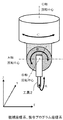
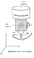
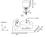
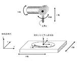
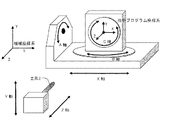
最近、図1,図2に示されるような3軸の回転軸を持ったヘッド回転型多軸加工機用の工具ヘッドが用いられるようになっている。また、テーブル回転2軸とヘッド回転1軸を有する混合型多軸加工機(図3参照)も用いられるようになっている。さらに、テーブル回転1軸とヘッド回転2軸を有する混合型多軸加工機(図4参照)や、テーブル回転3軸を有するテーブル回転型多軸加工機(図5参照)も機械構成としては考えられる。しかし、上述したような多軸構成の工作機械に対して、数値制御で工具先端点制御を行う技術思想はなかった。
そこで、本発明の課題は、上記のような回転軸を3軸備えた多軸加工機において、工具先端点制御を行う数値制御装置として、特に、指令プログラム座標系上で直線軸位置によって工具先端点位置を指令するとともに、ワーク(加工物)に対する相対的な工具方向指令を指令して加工を制御する工具先端点制御において、回転軸2軸を備えた5軸加工機で回避することが困難であった特異点近くでの回転軸の大きな動作を、加工誤差を発生することなく回避することであり、また、ほとんど同じ加工経路であっても、一方は特異点近くと判断され、他方は特異点近くと判断されないケースで、ほとんど同じ加工経路であるにも関わらず、大きく動作が相違することを防止することができる数値制御装置を提供することである。換言すれば、ほとんど同じ加工経路であれば特異点近くでの回転軸の大きな動作を回避した経路もほとんど同じとすることが可能な数値制御装置を本発明は提供することである。
Recently, a tool head for a rotary head type multi-axis machine having a three-axis rotation axis as shown in FIGS. 1 and 2 has been used. Further, a mixed multi-axis machine (see FIG. 3) having two table rotation axes and one head rotation axis is also used. Further, a mixed multi-axis machining machine (see FIG. 4) having a table rotation 1 axis and a
Accordingly, an object of the present invention is to provide a tool tip according to a linear axis position on a command program coordinate system as a numerical control device that performs tool tip point control in a multi-axis machining machine having three rotation axes as described above. In the tool tip point control that controls the machining by commanding a point position and commanding a relative tool direction command with respect to the workpiece (workpiece), it is difficult to avoid it with a 5-axis machine with two rotation axes This is to avoid the large movement of the rotating shaft near the singular point without causing a machining error. Even in almost the same machining path, one is judged to be near the singular point and the other is To provide a numerical control device capable of preventing a large difference in operation in a case where it is not determined to be close to a singular point even though the machining paths are almost the same. In other words, the present invention is to provide a numerical control apparatus capable of making the path that avoids a large motion of the rotating shaft near the singular point almost the same if the machining paths are almost the same.
上記のような回転軸を3軸備えた多軸加工機において、上記課題を実現するために、工具先端点制御を行う数値制御装置として、下記の特徴を備えた数値制御装置を本発明は提供する。 The present invention provides a numerical control device having the following characteristics as a numerical control device that performs tool tip point control in order to realize the above-mentioned problem in a multi-axis machining machine having three rotation axes as described above. To do.
本願の請求項1に係る発明は、テーブルに取り付けられたワークに対して少なくとも直線軸3軸および回転軸3軸でテーブルまたは工具ヘッドを回転する機構によって加工する多軸加工機において、指令プログラム座標系上で指令直線軸位置によって工具先端点位置を指令するとともに工具方向指令を指令して加工を行う数値制御装置において、補間周期毎に前記工具方向指令を補間し補間工具方向ベクトルを求め、該補間工具方向ベクトルから前記回転軸3軸の複数解を演算する回転軸複数解演算部と、前記複数解を合成して前記回転軸3軸の回転軸位置を演算する回転軸位置演算部と、補間周期毎に指令された前記工具先端点位置を補間し補間工具先端点位置を求め前記補間工具先端点位置、工具長補正量および前記回転軸3軸の回転軸位置から機械座標系上の前記直線軸3軸の直線軸位置を演算する直線軸位置演算部を有し、前記回転軸3軸について前記回転軸位置演算部で求めた前記回転軸位置へ移動し前記直線軸3軸について前記直線軸位置演算部で求めた前記直線軸位置へ移動することを特徴とする数値制御装置である。
請求項2に係る発明は、前記直線軸位置演算部は、前記補間工具方向ベクトルに前記工具長補正量を積算し前記補間工具先端点位置に加算し機械座標系上の前記直線軸3軸の直線軸位置を演算する直線軸位置演算部である請求項1に記載の数値制御装置である。
請求項3に係る発明は、前記回転軸位置演算部は、前記複数解を合成して前記回転軸3軸の回転軸位置を演算すると共に、該演算した回転軸3軸の回転軸位置から求められる工具方向ベクトルである検証工具方向ベクトルを求める回転軸位置演算部であり、前記直線軸位置演算部は、前記検証工具方向ベクトルに前記工具長補正量を積算し前記補間工具先端点位置に加算し機械座標系上の前記直線軸3軸の直線軸位置を演算する直線軸位置演算部である請求項1に記載の数値制御装置である。
請求項4に係る発明は、前記直線軸位置演算部は、前記工具長補正量、前記回転軸3軸の回転軸位置および前記補間工具先端点位置から後述する数10−3式によって機械座標系上の前記直線軸3軸の直線軸位置を演算する直線軸位置演算部である請求項1に記載の数値制御装置である。
The invention according to claim 1 of the present application is directed to a command program coordinate system in a multi-axis processing machine that processes a workpiece mounted on a table by a mechanism that rotates a table or a tool head with at least three linear axes and three rotation axes. In a numerical controller that performs machining by commanding a tool tip point position and commanding a tool direction command on the system, an interpolation tool direction vector is obtained by interpolating the tool direction command at each interpolation cycle, A rotation axis multiple solution calculation unit that calculates a plurality of solutions of the three rotation axes from an interpolation tool direction vector; a rotation axis position calculation unit that calculates the rotation axis position of the three rotation axes by combining the plurality of solutions; The tool tip point position commanded at each interpolation cycle is interpolated to obtain the interpolation tool tip point position, the interpolation tool tip point position, the tool length correction amount, and the three rotation axes of the rotation axis A linear axis position calculation unit that calculates a linear axis position of the three linear axes on the machine coordinate system from the position, and moves the three rotation axes to the rotation axis position obtained by the rotation axis position calculation unit. The numerical control device is characterized in that the three linear axes move to the linear axis position obtained by the linear axis position calculation unit.
In the invention according to
According to a third aspect of the present invention, the rotation axis position calculation unit calculates the rotation axis position of the three rotation shafts by combining the plurality of solutions and obtains the calculated rotation axis position of the three rotation axes. A rotation axis position calculation unit for obtaining a verification tool direction vector, which is a tool direction vector to be obtained, and the linear axis position calculation unit adds the tool length correction amount to the verification tool direction vector and adds it to the interpolation tool tip point position The numerical controller according to claim 1, wherein the numerical controller is a linear axis position calculation unit that calculates linear axis positions of the three linear axes on the machine coordinate system.
According to a fourth aspect of the present invention, the linear axis position calculation unit is configured to calculate a machine coordinate system from the tool length correction amount, the rotation axis position of the three rotation axes, and the interpolation tool tip point position according to Formula 10-3 described later. The numerical control device according to claim 1, wherein the numerical control device is a linear axis position calculation unit that calculates linear axis positions of the three linear axes above.
請求項5に係る発明は、前記複数解は、第1回転軸は動作しないとした場合の第1回転軸固定解、第2回転軸は動作しないとした場合の第2回転軸固定解、第3回転軸は動作しないとした場合の第3回転軸固定解であることを特徴とする請求項1〜4のいずれか1つに記載の数値制御装置である。
請求項6に係る発明は、前記複数解は、第1回転軸は1周期前の補間周期で求めた第1回転軸の移動量分移動するとした場合の第1回転軸固定解、第2回転軸は1周期前の補間周期で求めた第2回転軸の移動量分移動するとした場合の第2回転軸固定解、第3回転軸は1周期前の補間周期で求めた第3回転軸の移動量分移動するとした場合の第3回転軸固定解であることを特徴とする請求項1〜4のいずれか1つに記載の数値制御装置である。
In the invention according to claim 5, the plurality of solutions are a first rotating shaft fixed solution when the first rotating shaft is not operated, a second rotating shaft fixed solution when the second rotating shaft is not operated, 5. The numerical controller according to claim 1, wherein the numerical control device is a third rotating shaft fixed solution when the three rotating shafts do not operate.
In the invention according to claim 6, the plurality of solutions are the first rotation axis fixed solution and the second rotation when the first rotation axis is moved by the movement amount of the first rotation axis obtained in the interpolation cycle one cycle before. When the axis moves by the amount of movement of the second rotation axis obtained in the previous interpolation cycle, the third rotation axis is fixed, and the third rotation axis is the third rotation axis obtained in the previous interpolation cycle. 5. The numerical control device according to claim 1, wherein the numerical control device is a third rotating shaft fixed solution when moving by a moving amount.
請求項7に係る発明は、前記回転軸位置演算部は、前記複数解に対して移動量が小さいことを大きくする評価する評価値を計算し、前記複数解による移動量に前記評価値を積算して合成する回転軸位置演算部であることを特徴とする請求項1〜6のいずれか1つに記載の数値制御装置である。
請求項8に係る発明は、前記回転軸位置演算部は、求めた回転軸3軸の前記回転軸位置から前記検証工具方向ベクトルを求め前記補間工具方向ベクトルとの差が設定されたトレランス以内かどうかを検証し前記トレランス以内でなければ前記評価値について移動量が小さいことをより大きく評価するように再演算する回転軸位置の演算を繰り返す回転軸位置演算部であることを特徴とする請求項1〜7のいずれか1つに記載の数値制御装置である。
In the invention according to
According to an eighth aspect of the present invention, the rotation axis position calculation unit obtains the verification tool direction vector from the calculated rotation axis positions of the three rotation axes, and whether the difference from the interpolation tool direction vector is within a set tolerance. The rotation axis position calculation unit repeats the calculation of the rotation axis position for recalculation so as to evaluate whether the movement amount is small for the evaluation value if it is not within the tolerance. It is a numerical control apparatus as described in any one of 1-7.
請求項9に係る発明は、前記多軸加工機は、前記回転軸3軸で工具ヘッドを回転する多軸加工機であることを特徴とする請求項1〜8のいずれか1つに記載の数値制御装置である。
請求項10に係る発明は、前記多軸加工機は、前記回転軸3軸のうち回転軸2軸でテーブルを回転し他の回転軸1軸で工具ヘッドを回転する多軸加工機であることを特徴とする請求項1〜8のいずれか1つに記載の数値制御装置である。
The invention according to claim 9 is the multi-axis processing machine according to any one of claims 1 to 8, wherein the multi-axis processing machine is a multi-axis processing machine that rotates a tool head with the three rotation axes. It is a numerical control device.
The invention according to claim 10 is that the multi-axis machine is a multi-axis machine that rotates the table with two rotation axes among the three rotation axes and rotates the tool head with another rotation axis. The numerical control apparatus according to claim 1, wherein:
請求項11に係る発明は、前記多軸加工機は、前記回転軸3軸のうち回転軸2軸で工具ヘッドを回転し他の回転軸1軸でテーブルを回転する多軸加工機であることを特徴とする請求項1〜8のいずれか1つに記載の数値制御装置である。
請求項12に係る発明は、前記多軸加工機は、前記回転軸3軸でテーブルを回転する多軸加工機であることを特徴とする請求項1〜8のいずれか1つに記載の数値制御装置である。
According to an eleventh aspect of the present invention, the multi-axis processing machine is a multi-axis processing machine that rotates a tool head with two rotation axes among the three rotation axes and rotates a table with one rotation axis. The numerical control apparatus according to claim 1, wherein:
The invention according to
請求項13に係る発明は、前記工具方向指令は工具方向ベクトルによって指令されることを特徴とする請求項1〜12のいずれか1つに記載の数値制御装置である。
請求項14に係る発明は、前記工具方向指令は回転軸2軸の位置によって指令されることを特徴とする請求項1〜12のいずれか1つに記載の数値制御装置である。
請求項15に係る発明は、前記工具方向指令は回転軸3軸の位置によって指令されることを特徴とする請求項1〜12のいずれか1つに記載の数値制御装置である。
The invention according to claim 13 is the numerical control apparatus according to any one of claims 1 to 12, wherein the tool direction command is commanded by a tool direction vector.
The invention according to claim 14 is the numerical control device according to any one of claims 1 to 12, wherein the tool direction command is commanded by a position of two rotary shafts.
The invention according to
本発明により、回転軸を3軸備えた多軸加工機において、工具先端点制御を行う数値制御装置を提供できる。
特に、指令プログラム座標系上で直線軸位置によって工具先端点位置を指令するとともに、ワーク(加工物)に対する相対的な工具方向指令を指令して加工を制御する工具先端点制御において、回転軸2軸を備えた5軸加工機で回避することが困難であった特異点近くでの回転軸の大きな動作を、加工誤差を発生することなく回避でき、また、ほとんど同じ加工経路であっても、一方は特異点近くと判断され、他方は特異点近くと判断されないケースで、ほとんど同じ加工経路であるにも関わらず、大きく動作が相違することを防止することができる数値制御装置を提供できる。換言すれば、本発明により、ほとんど同じ加工経路であれば特異点近くでの回転軸の大きな動作を回避した加工経路もほとんど同じとすることが可能な数値制御装置を提供できる。
According to the present invention, it is possible to provide a numerical control device that performs tool tip point control in a multi-axis machine with three rotation axes.
In particular, in the tool tip point control in which the tool tip point position is commanded by the linear axis position on the command program coordinate system and the tool is commanded relative to the workpiece (workpiece) to control the machining, the
以下、本発明の実施形態を図面と共に説明する。
本発明は、工具先端点位置と工具方向が指令された時の工具先端点制御における回転軸の制御にその特長がある。そのため、工具先端点制御における工具方向の指令とそれに対する回転軸の制御について主に説明する。
Hereinafter, embodiments of the present invention will be described with reference to the drawings.
The present invention is characterized in the control of the rotation axis in the tool tip point control when the tool tip point position and the tool direction are commanded. Therefore, the tool direction command in the tool tip point control and the control of the rotation axis corresponding thereto will be mainly described.
一般に、ワークに対する相対的な工具方向(i,j,k)Tが与えられた時、それに対する回転軸3軸位置は解析的かつ一意には求まらない。これは、一般に逆運動学計算と呼ばれている。
そこで、本発明では、ある補間周期における工具方向(i,j,k)TからA,B,C軸位置を求める計算を概略的には次のように行う。ここでは、第1回転軸をA軸,第2回転軸をB軸,第3回転軸をC軸とする。ここで「T」は転置であるが、自明の場合は特に記載しない。
In general, when a tool direction (i, j, k) T relative to a workpiece is given, the position of the three rotation axes relative to the tool direction cannot be determined analytically and uniquely. This is generally called inverse kinematic calculation.
Therefore, in the present invention, the calculation for obtaining the A, B, and C axis positions from the tool direction (i, j, k) T in a certain interpolation period is roughly performed as follows. Here, the first rotation axis is the A axis, the second rotation axis is the B axis, and the third rotation axis is the C axis. Here, “ T ” is transposition, but it is not particularly described in the case of self-evident.
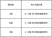
図6は、1軸を固定させ、残り2軸の位置を求めることを説明する図である。図6に示されるように、A,B,C軸位置のうち1軸を固定させ、残り2軸の位置を求める。1軸を固定させれば、残り2軸の位置は解析的かつ一意に求めることができる。 FIG. 6 is a diagram illustrating that one axis is fixed and the positions of the remaining two axes are obtained. As shown in FIG. 6, one of the A, B, and C axis positions is fixed, and the positions of the remaining two axes are obtained. If one axis is fixed, the positions of the remaining two axes can be obtained analytically and uniquely.
第1回転軸固定解(A軸固定解)、第2回転軸固定解(B軸固定解)、第3回転軸固定解(C時固定解)に対して、移動量が小さいことを大きく評価する評価値を計算し、それぞれの解による移動量に積算して合成する。ここで、第1回転軸固定解(A軸固定解)、第2回転軸固定解(B軸固定解)、第3回転軸固定解(C時固定解)には、三角関数計数から発生する2πラジアンごとの周期解や正負の解があるので、それらの解のうち直前の補間周期におけるA,B,C軸位置により近い解を選択しておく。なお、第1回転軸(A軸),第2回転軸(B軸),第3回転軸(C軸)を備えた多軸加工機の構成の例としては、図1,図2,図3,図4,図5に示したとおりである。ここでは、A軸はX軸周りの回転軸、B軸はY軸周りの回転軸、C軸はZ軸周りの回転軸とする。 Largely evaluated that the amount of movement is small compared to the first rotating shaft fixed solution (A-axis fixed solution), the second rotating shaft fixed solution (B-axis fixed solution), and the third rotating shaft fixed solution (C-time fixed solution). The evaluation value to be calculated is calculated and integrated by adding to the movement amount by each solution. Here, the first rotation axis fixed solution (A axis fixed solution), the second rotation axis fixed solution (B axis fixed solution), and the third rotation axis fixed solution (C time fixed solution) are generated from trigonometric function counting. Since there are periodic solutions and positive and negative solutions every 2π radians, a solution closer to the A, B, and C axis positions in the immediately preceding interpolation cycle is selected from these solutions. Examples of the configuration of the multi-axis processing machine provided with the first rotation axis (A axis), the second rotation axis (B axis), and the third rotation axis (C axis) are shown in FIGS. FIG. 4 and FIG. Here, the A axis is the rotation axis around the X axis, the B axis is the rotation axis around the Y axis, and the C axis is the rotation axis around the Z axis.
このことにより、回転軸3軸の座標系における移動量のできるだけ小さい回転軸3軸の位置が得られる。その結果、特異点近傍における回転軸の大きな動作を防ぐことができる。 As a result, the position of the three rotation shafts with the smallest possible movement amount in the coordinate system of the three rotation shafts is obtained. As a result, a large operation of the rotating shaft in the vicinity of the singular point can be prevented.
また、本発明においては、特に特異点近傍という範囲を設定する必要はない。そのため、ほとんど同じ経路であっても一方は特異点近くと判断され、他方は特異点近くと判断されないケースでほとんど同じ経路なのにもかかわらず大きく動作が相違するということも発生しない。つまり、ほとんど同じ経路であれば、特異点近くでの回転軸の動作はほとんど同じことになる。 In the present invention, it is not particularly necessary to set a range near the singular point. For this reason, even if the paths are almost the same, it is determined that one is close to a singular point and the other is not determined to be close to a singular point. That is, if the paths are almost the same, the operation of the rotating shaft near the singular point is almost the same.
●本発明の第1の実施形態
第1の実施形態として、工具方向が工具方向ベクトル(ic,jc,kc)として指令される例を説明する。
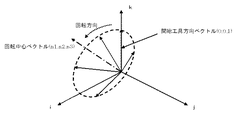
図1,図2のヘッド回転型多軸加工機を想定する。各回転軸中心は交差する。A,B軸は−90度〜90度が可動範囲、C軸は何回転でも動作可能とする。A軸位置をa(ラジアン)、B軸位置をb(ラジアン)、C軸位置をc(ラジアン)で表す。a=b=c=0の時に工具方向は図1,図2のようなZ軸方向とする。機械座標系は機械に固定された座標系であり、指令プログラム座標系は指令プログラムにおける指令位置を表す座標系である。指令プログラムにおいて、指令プログラム座標系上での工具先端点位置が直線軸X,Y,Z軸の指令位置(xc,yc,zc)で指令され、工具方向指令が指令工具方向ベクトル(ic,jc,kc)で指令され、補間周期毎に補間されて補間工具先端点位置(xi,yi,zi)および補間工具方向ベクトル(i,j,k)が求められる。ここで、(i,j,k)は単位ベクトルとする。
First Embodiment of the Invention As a first embodiment, an example in which a tool direction is commanded as a tool direction vector (ic, jc, kc) will be described.
The head rotating type multi-axis machining machine shown in FIGS. 1 and 2 is assumed. Each rotation axis center intersects. The A and B axes can be operated in a range of −90 degrees to 90 degrees, and the C axis can be operated any number of rotations. The A-axis position is represented by a (radian), the B-axis position is represented by b (radian), and the C-axis position is represented by c (radian). When a = b = c = 0, the tool direction is the Z-axis direction as shown in FIGS. The machine coordinate system is a coordinate system fixed to the machine, and the command program coordinate system is a coordinate system representing command positions in the command program. In the command program, the tool tip point position on the command program coordinate system is commanded by command positions (xc, yc, zc) of the linear axes X, Y, and Z axes, and the tool direction command is a command tool direction vector (ic, jc). , Kc) and is interpolated at every interpolation period to obtain the interpolation tool tip point position (xi, yi, zi) and the interpolation tool direction vector (i, j, k). Here, (i, j, k) is a unit vector.
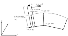
図7は、図1,図2に示されるヘッド回転型多軸加工機の補間工具方向ベクトルを説明する図である。図中、(xp,yp,zp)は後述する直線軸位置である。
補間工具方向ベクトル(i,j,k)とa,b,cの間には数1式の関係が成り立つ。
この変換式は機械構成に依存する。
FIG. 7 is a diagram for explaining an interpolation tool direction vector of the head rotary multi-axis machine shown in FIGS. 1 and 2. In the figure, (xp, yp, zp) is a linear axis position described later.
The relationship of Formula 1 is established between the interpolation tool direction vector (i, j, k) and a, b, c.
This conversion formula depends on the machine configuration.

(i,j,k)が与えられた時に(a,b,c)は解析的に一意に求めることはできない。そこで、A軸位置を固定させた場合のA軸固定解(第1回転軸固定解)、B軸位置を固定させた場合のB軸固定解(第2回転軸固定解)、C軸位置を固定させた場合のC軸固定解(第3回転軸固定解)を求める。各軸の固定のさせ方としては、前回の補間周期で求められた各軸位置を採用する。あるいは、前回の補間周期での各軸移動量が今回の補間周期でも同じであるとした場合の各軸位置を採用する方法などがある。また、前々回の補間周期と前回の補間周期での移動量の差を加速度としてさらに加えるなど多様な方法がある。
ここでは、A軸位置を固定させた場合、B軸位置を固定させた場合、C軸位置を固定させた場合をそれぞれ説明する。
When (i, j, k) is given, (a, b, c) cannot be uniquely determined analytically. Therefore, the A-axis fixed solution (first rotating shaft fixed solution) when the A-axis position is fixed, the B-axis fixed solution (second rotating shaft fixed solution) when the B-axis position is fixed, and the C-axis position. A C-axis fixed solution (third rotation axis fixed solution) when fixed is obtained. As a method of fixing each axis, the position of each axis obtained in the previous interpolation cycle is employed. Alternatively, there is a method of adopting the position of each axis when the movement amount of each axis in the previous interpolation cycle is the same in the current interpolation cycle. In addition, there are various methods such as adding the difference of the movement amount between the previous interpolation cycle and the previous interpolation cycle as acceleration.
Here, a case where the A-axis position is fixed, a case where the B-axis position is fixed, and a case where the C-axis position is fixed will be described.
<A軸固定解(第1回転軸固定解)>
aは前回の補間周期で求められたA軸位置とする。あるいは前回の補間周期でのA軸移動量が今回の補間周期でも同じであるとすることにより固定し、それをa1とする。つまり、前回の補間周期で求められたA軸位置をa0,前回の補間周期でのA軸移動量をΔa0とすると、a1=a0とする、あるいは、a1=a0+Δa0とすることによりaを固定する。
<A-axis fixed solution (first rotary shaft fixed solution)>
a is the A-axis position obtained in the previous interpolation cycle. Alternatively, it is fixed by assuming that the A-axis movement amount in the previous interpolation cycle is the same in the current interpolation cycle, and is set as a1. That is, if the A-axis position obtained in the previous interpolation cycle is a0, and the A-axis movement amount in the previous interpolation cycle is Δa0, a1 = a0 or a1 = a0 + Δa0 to fix a. .
第1回転軸固定解のb,cをb1,c1とすると、数1式を解くことによってa1,i,j,kから数2式のように計算できる。nは整数である。
Assuming that b and c of the first rotation axis fixed solution are b1 and c1, by calculating equation 1, it can be calculated from equation a1, i, j, k as
ここで、+,−の符号や整数nの決定は、b1,c1が前回の補間周期におけるB,C軸位置に近い解となるように決定する。または、前回の補間周期におけるA軸固定解のB,C軸位置に近い解となるように決定することもできる。
また、b1計算におけるcos-1の( )中の分母、分子の両方が0(ゼロ)の場合は不定となり、また、cos-1の( )中の絶対値が1より大である場合は解なしとなる。
その場合、b1は前回の補間周期でのB軸位置とする、あるいは後述する第1回転軸固定解の評価値を0とする。c1計算についても同様である。
Here, the signs of + and-and the integer n are determined so that b1 and c1 are close to the B and C axis positions in the previous interpolation cycle. Alternatively, it can be determined to be a solution close to the B and C axis positions of the A axis fixed solution in the previous interpolation cycle.
In addition, if both the denominator and numerator of cos -1 in () in b1 calculation are 0 (zero), it is undefined. If the absolute value of cos -1 in () is greater than 1, None.
In this case, b1 is the B-axis position in the previous interpolation cycle, or the evaluation value of the first rotation axis fixed solution described later is set to 0. The same applies to the c1 calculation.
このような、軸位置を固定する方法、+,−の符号や整数値の決定、および不定、解なしに対する処理は第2回転軸固定解、第3回転軸固定解の計算においても同様である。 The method for fixing the shaft position, the determination of the sign of +, − and the integer value, and the processing for indefinite and no solution are the same in the calculation of the second rotation axis fixed solution and the third rotation axis fixed solution. .
<B軸固定解(第2回転軸固定解)>
bは前回の補間周期で求められたB軸位置とする、あるいは前回の補間周期でのB軸移動量が今回の補間周期でも同じであるとすることにより固定し、それをb2とする。第2回転軸固定解のa,cをa2,c2とすると、数1式を解くことによってb2,i,j,kから数3式のように計算できる。mは整数である。
<B-axis fixed solution (second rotary shaft fixed solution)>
b is the B-axis position obtained in the previous interpolation cycle, or fixed by assuming that the B-axis movement amount in the previous interpolation cycle is the same in the current interpolation cycle, and this is b2. Assuming that a and c of the second rotation axis fixed solution are a2 and c2, by calculating equation 1, it can be calculated from equation b3, i, j, k as equation 3. m is an integer.
<C軸固定解(第3回転軸固定解)>
cは前回の補間周期で求められたC軸位置とする、あるいは前回の補間周期でのC軸移動量が今回の補間周期でも同じであるとすることにより固定し、それをc3とする。第3回転軸固定解のa,bをa3,b3とすると、数1式を解くことによってc3,i,j,kから数4式のように計算することができる。
<C-axis fixed solution (third rotary shaft fixed solution)>
Let c be the C-axis position obtained in the previous interpolation cycle, or fix the C-axis movement amount in the previous interpolation cycle to be the same in the current interpolation cycle, and let it be c3. Assuming that a and b of the third rotating shaft fixed solution are a3 and b3, it is possible to calculate from c3, i, j, and k as shown in Equation 4 by solving Equation 1.
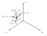
A,B,C軸の固定する位置を前回の補間周期で求められたA,B,C軸位置(a0,b0,c0)として計算した場合の各回転軸固定解をA,B,C軸を座標として図示すると図8のようになる。 Each rotation axis fixed solution when calculating the fixed positions of the A, B, and C axes as the A, B, and C axis positions (a0, b0, c0) obtained in the previous interpolation cycle is the A, B, and C axes. Is shown as coordinates as shown in FIG.
次に、第1回転軸固定解、第2回転軸固定解、第3回転軸固定解に対するそれぞれの仮評価値V1’,V2’,V3’を求める。仮評価値は各解による各軸(A,B,C軸)合成移動量が小さいことを大きく評価する値とする。例えば、数5式の計算によって求められる計算値を仮評価値とする。ここで、a0,b0,c0は前回の補間周期におけるA,B,C軸位置である。wは移動量が小さいことをどの程度大きく評価するかを示すべき乗値(べき乗数)である。 Next, provisional evaluation values V1 ', V2', V3 'for the first rotating shaft fixed solution, the second rotating shaft fixed solution, and the third rotating shaft fixed solution are obtained. The provisional evaluation value is a value that greatly evaluates that the combined movement amount of each axis (A, B, C axis) by each solution is small. For example, a calculated value obtained by the calculation of Equation 5 is used as a temporary evaluation value. Here, a0, b0, and c0 are the A, B, and C axis positions in the previous interpolation cycle. w is a power value (power multiplier) indicating how much the small movement amount is evaluated.
これらの仮評価値は一つの例であり、各解による各軸(A,B,C軸)合成移動量が小さいことを大きく評価する値であれば他の計算式もありえる。例えば、V1’の計算において、数6式のように定数BV1を加えてもよいし、分母を各移動量の絶対値にしてもよいし、分子を定数NV1にしてもよい。V2’,V3’についても同様である。 These provisional evaluation values are only an example, and other calculation formulas may be used as long as they are values that greatly evaluate that the combined movement amount of each axis (A, B, C axis) by each solution is small. For example, in the calculation of V1 ', a constant BV1 may be added as shown in Equation 6, the denominator may be an absolute value of each movement amount, and the numerator may be a constant NV1. The same applies to V2 'and V3'.
仮評価値V1’, V2’,V3’を正規化したものを評価値V1,V2,V3とする。そして、数7式のように、評価値V1,V2,V3を第1回転軸固定解、第2回転軸固定解、第3回転軸固定解による移動量に積算し合成する。
The normalized evaluation values V1 ', V2', V3 'are defined as evaluation values V1, V2, V3. Then, as shown in
これによって、今回の補間周期におけるA,B,C軸の移動すべき回転軸位置(a,b,c)が求まる。ただし、第1回転軸固定解、第2回転軸固定解、第3回転軸固定解は数1式に対する解であるが、数7式で求めたa,b,cは厳密には数1式の解ではない。そのため、a,b,cを数1式に代入してi,j,kを求めて検証する。数7式で求めたa,b,cを数1式に代入して求めたi,j,kを検証工具方向ベクトル(iv,jv,kv)とすると、数8式のようにDを求め、あらかじめ設定されているトレランスD0と比較し、トレランスD0よりも小さければa,b,cを今回の補間周期におけるA,B,C軸の移動すべき位置とする。トレランスD0よりも大きければ、wを大きくして再度数5式、数6式、数7式、数8式の計算を行い、DがトレランスD0より小さくなるまで繰り返す。ここで、wを大きくするには、w=w+dwと一定値dwを加算する、w=kw*wと1より大の係数kwを積算するなどの方法がある。
As a result, the rotation axis positions (a, b, c) to which the A, B, C axes should move in the current interpolation cycle are obtained. However, the first rotating shaft fixed solution, the second rotating shaft fixed solution, and the third rotating shaft fixed solution are solutions to Equation 1, but a, b, and c obtained by
![]()
![]()
次に、工具2の動作に関するシミュレーション例を説明する。
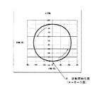
開始工具方向ベクトル(0,0,1)とし、それを回転中心ベクトル(n1,n2,n3)の周りに少しずつ回転させながら工具方向ベクトルとして指令するとする。工具方向ベクトル(0,0,1)の時がA軸、B軸位置が0となりC軸位置が不定となる特異点である。ここで、n1,n2,n3は数9式のように与えるとする。工具方向ベクトルは図9のように変化する。
Next, a simulation example regarding the operation of the
It is assumed that the start tool direction vector (0, 0, 1) is used, and the tool direction vector is commanded while being gradually rotated around the rotation center vector (n1, n2, n3). The tool direction vector (0, 0, 1) is a singular point where the A-axis and B-axis positions are 0 and the C-axis position is indefinite. Here, n1, n2, and n3 are given as shown in Equation 9. The tool direction vector changes as shown in FIG.
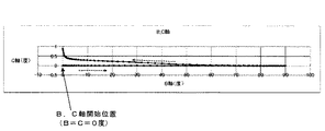
このように指令される指令工具方向ベクトル(ic,jc,kc)に対して本発明を適用した場合、A,B軸の動作を図示すると図10のようになり、B,C軸の動作を図示すると、図11のようになる。特異点近傍での回転軸、特にC軸の大きな動作は発生していない。ここで、図10は、A,B軸の動作を説明する図である。また、図11は、B,C軸の動作を説明する図である。 When the present invention is applied to the commanded tool direction vector (ic, jc, kc) commanded in this way, the operations of the A and B axes are shown in FIG. When illustrated, it is as shown in FIG. There is no significant movement of the rotation axis, particularly the C axis, near the singular point. Here, FIG. 10 is a diagram for explaining the operations of the A and B axes. FIG. 11 is a diagram for explaining the operations of the B and C axes.
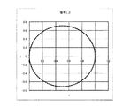
また、指令される指令工具方向ベクトル(ic,jc,kc)、およびそれを補間した補間工具方向ベクトル(i,j,k)のi,j成分を図示した図が図12であり、それに対して作成されたA,B,C軸位置から検証工具方向ベクトル(iv,jv,kv)を再度作成してiv,jv成分を図示した図が図13である。図13に示されるように、正しく工具方向ベクトルが再生されているので指令とおりの加工が行われる。 FIG. 12 is a diagram illustrating the commanded tool direction vector (ic, jc, kc) to be commanded and the i and j components of the interpolated tool direction vector (i, j, k) obtained by interpolating the commanded tool direction vector (ic, jc, kc). FIG. 13 is a diagram illustrating the iv and jv components by re-creating the verification tool direction vector (iv, jv, kv) from the A, B, and C axis positions created in this way. As shown in FIG. 13, since the tool direction vector is correctly reproduced, machining as instructed is performed.
直線軸3軸については、プログラム指令上で指令された工具先端点位置(xc,yc,zc)を補間周期毎に補間し補間工具先端点位置(xi,yi,zi)を求め、上記で求められている補間工具方向ベクトル(i,j,k)または検証工具方向ベクトル(iv,jv,kv)に工具長補正量(Th)を積算し補間工具先端点位置に加算し直線軸3軸の直線軸位置(xp,yp,zp)を演算する(図7参照)。直線軸位置(xp,yp,zp)は工具ヘッドの回転中心である。数10−1式は補間工具方向ベクトル(i,j,k)に工具長補正量(Th)を積算して得られるその直線軸3軸の直線軸位置(xp,yp,zp)の演算を示す。数10−2式は検証工具方向ベクトル(iv,jv,kv)に工具長補正量(Th)を積算して得られるその直線軸3軸の直線軸位置(xp,yp,zp)の演算を示す。なお、数10−3式のように、A軸位置、B軸位置、C軸位置が0の時の工具長補正ベクトル(Th*(0,0,1))にa,b,cによるマトリックスを積算してその直線軸3軸の直線軸位置(xp,yp,zp)を得る方法もあるが、数7式で求められた(a,b,c)を数1式に代入して求めたのが(iv,jv,kv)であるから、数10−3式は数10−2式と全く同等である。つまり、数10−3式のように、A軸位置、B軸位置、C軸位置が0の時の工具長補正ベクトル(Th*(0,0,1))にa,b,cによるマトリックスを積算してその直線軸3軸の直線軸位置(xp,yp,zp)を得る方法は、数10−2式のように検証工具方向ベクトル(iv,jv,kv)に工具長補正量(Th)を積算してその直線軸3軸の直線軸位置(xp,yp,zp)を得る方法と同等である。
For the three linear axes, the tool tip point position (xc, yc, zc) commanded on the program command is interpolated for each interpolation cycle to obtain the interpolated tool tip point position (xi, yi, zi). The tool length correction amount (Th) is added to the interpolation tool direction vector (i, j, k) or verification tool direction vector (iv, jv, kv) that has been added, and added to the tip position of the interpolation tool. The linear axis position (xp, yp, zp) is calculated (see FIG. 7). The linear axis position (xp, yp, zp) is the rotation center of the tool head. Equation 10-1 calculates the linear axis position (xp, yp, zp) of the three linear axes obtained by adding the tool length correction amount (Th) to the interpolation tool direction vector (i, j, k). Show. Equation (10-2) calculates the linear axis position (xp, yp, zp) of the three linear axes obtained by integrating the tool length correction amount (Th) to the verification tool direction vector (iv, jv, kv). Show. As shown in Equation 10-3, the tool length correction vector (Th * (0,0,1)) when the A-axis position, B-axis position, and C-axis position are 0 is a matrix of a, b, and c. There is also a method of obtaining the linear axis position (xp, yp, zp) of the three linear axes by subtracting the values, but substituting (a, b, c) obtained by
●本発明の第2の実施形態
第1の実施形態では、工具方向が指令工具方向ベクトル(ic,jc,kc)として指令される例を述べたが、従来の5軸加工機における工具先端点制御では回転軸2軸によって工具方向が指令される場合も多い。例えば、図1におけるA軸を持たない従来の5軸加工機を想定した場合、B,C軸の指令によって工具方向を指令し工具先端点制御による加工を行う場合も多い。そのように工具方向指令がB,C軸の指令(bc,cc)で指令された場合、それを数11式のように指令工具方向ベクトル(ic,jc,kc)に変換し工具方向として指令工具方向ベクトル(ic,jc,kc)が指令されたとみなして第1の実施形態と同じ処理を行うことによって第、第1の実施形態と同様に回転軸3軸を制御することもできる。したがって、B,C軸指令による従来の5軸加工機の工具先端点制御の指令プログラムに対しても、第1の実施形態と同様に回転軸3軸を制御することもできる。
Second Embodiment of the Present Invention In the first embodiment, the example in which the tool direction is commanded as the command tool direction vector (ic, jc, kc) has been described. However, the tool tip point in a conventional 5-axis machine In control, the tool direction is often commanded by two rotation axes. For example, assuming a conventional 5-axis machine with no A-axis in FIG. 1, there are many cases where machining is performed by tool tip point control by commanding the tool direction by commands of the B and C axes. When the tool direction command is commanded by the B and C axis commands (bc, cc), it is converted into a command tool direction vector (ic, jc, kc) as shown in Equation 11 and commanded as the tool direction. By assuming that the tool direction vector (ic, jc, kc) has been commanded and performing the same processing as in the first embodiment, it is possible to control the three rotation axes as in the first embodiment. Therefore, it is also possible to control the three rotary shafts in the same manner as in the first embodiment with respect to the command program for controlling the tool tip of the conventional 5-axis machine with the B and C axis commands.
A,C軸の回転軸2軸を持った5軸加工機や、A,B軸の回転軸2軸を備えた5軸加工機の指令プログラムに対しても同様である。 The same applies to a command program for a five-axis machine having two rotation axes of A and C and a five-axis machine having two rotation axes of A and B.
●本発明の第3の実施形態
本発明の第1の実施形態では、工具方向が指令工具方向ベクトル(ic,jc,kc)として指令される例を述べたが、回転軸3軸によって工具方向が指令される場合にも対応可能である。
工具方向指令はA,B,C軸の指令(ac,bc,cc)で指令された場合、それを数12式のように指令工具方向ベクトル(ic,jc,kc)に変換し、工具方向として指令工具方向ベクトル(ic,jc,kc)が指令されたとみなして本発明の第1の実施形態と同じ処理を行うことによって、回転軸3軸によって工具方向指令が指令される工具先端点制御の指令プログラムに対しても、本発明の第1の実施形態と同様に回転軸3軸を制御することができる。
Third Embodiment of the Present Invention In the first embodiment of the present invention, the example in which the tool direction is commanded as the command tool direction vector (ic, jc, kc) has been described. It is possible to cope with the case where the command is issued.
When the tool direction command is commanded by A, B, and C axis commands (ac, bc, cc), it is converted into a command tool direction vector (ic, jc, kc) as shown in
同様に、工具方向をロール・ピッチ・ヨー角で指令する、オイラー角で指令するなどの様々な指令方法にも対応可能である。 Similarly, various command methods such as commanding the tool direction by roll, pitch, and yaw angle, and commanding by Euler angle can be supported.
●本発明の第4の実施形態
図3の混合型多軸加工機(テーブル回転2軸+工具ヘッド回転1軸)を想定する。テーブル回転2軸の回転中心は交差し、指令プログラム座標系は回転テーブル上に存在しその原点はテーブル回転2軸の回転中心と一致する。指令プログラム座標系は回転テーブルの回転とともに回転する。指令工具方向ベクトル(ic,jc,kc)は指令プログラム座標系で指令される。A,B軸は−90度〜90度が可動範囲、C軸は何回転でも動作可能とする。A軸位置をa(ラジアン),B軸位置をb(ラジアン),C軸位置をc(ラジアン)で表す。a=b=c=0の時に工具方向は図3のようなZ軸方向とする。
Fourth Embodiment of the Present Invention Assume the mixed multi-axis machine (
指令プログラムにおいて指令プログラム座標系上での工具先端点位置が、直線軸X,Y,Z軸の指令位置(xc,yc,zc)で指令され工具方向指令が指令工具方向ベクトル(ic,jc,kc)で指令され、補間周期毎に補間されて補間工具先端点位置(xi,yi,zi)および補間工具方向ベクトル(i,j,k)が求められる。補間工具方向ベクトル(i,j,k)とa,b,cの間には数13式のような関係が成り立つ。なお、この変換式は機械構成に依存する。 In the command program, the tool tip point position on the command program coordinate system is commanded by command positions (xc, yc, zc) of the linear axes X, Y, and Z, and the tool direction command is commanded to the command tool direction vector (ic, jc, kc) and is interpolated at every interpolation period to obtain the interpolation tool tip point position (xi, yi, zi) and the interpolation tool direction vector (i, j, k). The relationship shown in Equation 13 is established between the interpolation tool direction vector (i, j, k) and a, b, c. This conversion formula depends on the machine configuration.
後は、本発明の第1の実施形態と同様であるので、記載を省略する。また、第4の実施形態である図3の混合型多軸加工機(テーブル回転2軸+工具ヘッド回転1軸)においても、本発明の第2の実施形態、および本発明の第3の実施形態のように指令工具方向ベクトルの代わりに回転軸の指令で工具方向を指令する指令方法を同様に適用できる。この点は後述の第5の実施形態、第6の実施形態においても同様である。
ただし、直線軸位置(xp,yp,zp)の演算については、第1の実施形態における数10式に対して、テーブル上にある指令プログラム座標系から機械座標系に変換するためにC軸、A軸のテーブル回転軸分の逆変換を行う。(Ptx,Pty,Ptz)は機械座標系上の指令プログラム座標系原点位置である。数14式は数10−1式に対する式である。数10−2式に対する式とするには、数14式の(i,j,k)を(iv,jv,kv)とすればよい。数14式で示されるような直線軸位置(xp,yp,zp)の演算において、テーブル上にある指令プログラム座標系から機械座標系への変換の演算を行うことについては第5の実施形態、第6の実施形態も同様である。
Since the rest is the same as that of the first embodiment of the present invention, the description is omitted. Also in the mixed type multi-axis processing machine (
However, with respect to the calculation of the linear axis position (xp, yp, zp), the C axis in order to convert from the command program coordinate system on the table to the machine coordinate system with respect to Equation 10 in the first embodiment, Reverse conversion is performed for the table rotation axis of the A axis. (Ptx, Pty, Ptz) is the command program coordinate system origin position on the machine coordinate system. Expression 14 is an expression for Expression 10-1. In order to obtain an equation for the equation 10-2, (i, j, k) in the equation 14 may be changed to (iv, jv, kv). In the calculation of the linear axis position (xp, yp, zp) as shown in the equation 14, the fifth embodiment is described for calculating the conversion from the command program coordinate system on the table to the machine coordinate system. The same applies to the sixth embodiment.
●本発明の第5の実施形態
図4の混合型多軸加工機(テーブル回転1軸+工具ヘッド回転2軸)を想定する。ヘッド回転2軸の回転中心は交差し、指令プログラム座標系は回転テーブル上に存在しその原点はテーブル回転軸の回転中心と一致する。指令プログラム座標系は回転テーブルの回転とともに回転する。指令工具方向ベクトル(ic,jc,kc)は指令プログラム座標系上で指令される。A,B軸は−90度〜90度が可動範囲、C軸は何回転でも動作可能とする。A軸位置をa(ラジアン),B軸位置をb(ラジアン),C軸位置をc(ラジアン)で表す。a=b=c=0の時に工具方向は図3のようなZ軸方向とする。
Fifth Embodiment of the Present Invention Assume the mixed multi-axis processing machine (table rotation 1 axis +
指令プログラムにおいて指令プログラム座標系上での工具先端点位置が直線軸X,Y,Z軸の指令位置(xc,yc,zc)で指令され工具方向指令が指令工具方向ベクトル(ic,jc,kc)で指令され補間周期毎に補間されて補間工具先端点位置(xi,yi,zi)および補間工具方向ベクトル(i,j,k)が求められる。補間工具方向ベクトル(i,j,k)とa,b,cの間には数15式のような関係が成り立つ。
In the command program, the tool tip point position on the command program coordinate system is commanded by command positions (xc, yc, zc) of the linear axes X, Y, and Z axes, and the tool direction command is commanded by the command tool direction vector (ic, jc, kc). ) And the interpolation tool tip position (xi, yi, zi) and the interpolation tool direction vector (i, j, k) are obtained by interpolation every interpolation cycle. The relationship shown in
後は、第1の実施形態、および第4の実施形態と同様であるので、記載を省略する。 Since the subsequent steps are the same as those in the first embodiment and the fourth embodiment, description thereof is omitted.
●本発明の第6の実施形態
図5のテーブル回転型多軸加工機を想定する。テーブル回転軸3軸の回転中心は交差し、指令プログラム座標系は回転テーブル上に存在しその原点はテーブル回転軸の回転中心と一致する。指令プログラム座標系は回転テーブルの回転とともに回転する。指令工具方向ベクトル(ic,jc,kc)は指令プログラム座標系で指令される。A,B軸は−90度〜90度が可動範囲、C軸は何回転でも動作可能とする。A軸位置をa(ラジアン),B軸位置をb(ラジアン),C軸位置をc(ラジアン)で表す。a=b=c=0の時に工具方向は図3のようなZ軸方向とする。
[Sixth Embodiment of the Present Invention] Assume the table rotary type multi-axis machine of FIG. The rotation centers of the three table rotation axes intersect, the command program coordinate system exists on the rotation table, and its origin coincides with the rotation center of the table rotation axis. The command program coordinate system rotates with the rotation of the rotary table. The command tool direction vector (ic, jc, kc) is commanded in the command program coordinate system. The A and B axes can be operated in a range of −90 degrees to 90 degrees, and the C axis can be operated any number of rotations. The A-axis position is represented by a (radian), the B-axis position is represented by b (radian), and the C-axis position is represented by c (radian). When a = b = c = 0, the tool direction is the Z-axis direction as shown in FIG.
指令プログラムにおいて指令プログラム座標系上での工具先端点位置が直線軸X,Y,Z軸の指令位置(xc,yc,zc)で指令され工具方向指令が指令工具方向ベクトル(ic,jc,kc)で指令され補間周期毎に補間され補間工具先端点位置(xi,yi,zi)および補間工具方向ベクトル(i,j,k)が求められる。補間工具方向ベクトル(i,j,k)とa,b,cの間には数16式のような関係が成り立つ。この変換式は機械構成に依存する。 In the command program, the tool tip point position on the command program coordinate system is commanded by command positions (xc, yc, zc) of the linear axes X, Y, and Z axes, and the tool direction command is commanded by the command tool direction vector (ic, jc, kc). ) And the interpolation tool tip point position (xi, yi, zi) and the interpolation tool direction vector (i, j, k) are obtained by interpolation every interpolation cycle. The relationship shown in Expression 16 is established between the interpolation tool direction vector (i, j, k) and a, b, c. This conversion formula depends on the machine configuration.
後は、第1の実施形態、および第4の実施形態と同様の計算であるので、記載を省略する。 Since the subsequent calculations are the same as those in the first embodiment and the fourth embodiment, description thereof is omitted.
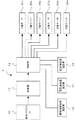
図14は、回転軸3軸を備えた多軸加工機を制御する数値制御装置の機能ブロック図である。数値制御装置1は、指令プログラム10を解析部12で解析し補間部14で補間し各軸サーボ20x,20y,20z,20a,20b,20cを駆動する。本発明に係る回転軸複数解演算部15、回転軸位置演算部17、直線軸位置演算部19は図14に示されるように補間部に属する。
FIG. 14 is a functional block diagram of a numerical control apparatus that controls a multi-axis machining apparatus having three rotation axes. The numerical control apparatus 1 analyzes the command program 10 with the
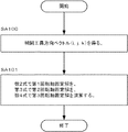
図15は、本発明に係る回転軸複数解演算部を説明するフロチャートである。以下、各ステップに従って説明する。
●[ステップSA100]補間工具方向ベクトル(i,j,k)を得る。
●[ステップSA101]数2式で第1回転軸固定解を、第3式で第2回転軸固定解を、第4式で第3回転軸固定解を演算し、処理を終了する。
FIG. 15 is a flowchart for explaining the rotating shaft multiple solution calculation unit according to the present invention. Hereinafter, it demonstrates according to each step.
[Step SA100] An interpolation tool direction vector (i, j, k) is obtained.
[Step SA101] The first rotating shaft fixed solution is calculated by
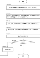
図16は、本発明に係る回転軸位置演算部を説明するフロチャートである。以下、各ステップに従って説明する。
●[ステップSB100]前回の補間周期での回転軸補間位置(a0,b0,c0)を得る。
●[ステップSB101]数5式で、第1回転軸固定解、第2回転軸固定解、第3回転軸固定解に対する仮評価値V1’,V2’,V3’を演算する。
●[ステップSB102]V1’,V2’,V3’を正規化し、各評価値V1,V2,V3を演算する。
●[ステップSB103]数7式でA,B,C軸の移動すべき回転軸位置(a,b,c)を演算する。
●[ステップSB104]数8式でDを演算する。
●[ステップSB105]DはD0より小さいか否か判断し、小さい場合には処理を終了し、小さくない場合にはステップSB106へ移行する。
●[ステップSB106]w=w+dwを演算し、ステップSB101へ戻り処理を継続する。
FIG. 16 is a flowchart illustrating the rotation axis position calculation unit according to the present invention. Hereinafter, it demonstrates according to each step.
[Step SB100] The rotation axis interpolation position (a0, b0, c0) in the previous interpolation cycle is obtained.
[Step SB101] The provisional evaluation values V1 ′, V2 ′, and V3 ′ for the first rotating shaft fixed solution, the second rotating shaft fixed solution, and the third rotating shaft fixed solution are calculated using Equation 5.
[Step SB102] V1 ′, V2 ′, and V3 ′ are normalized, and the evaluation values V1, V2, and V3 are calculated.
[Step SB103] The rotational axis positions (a, b, c) of the A, B, and C axes that are to be moved are calculated using Equation (7).
[Step SB104] D is calculated using equation (8).
[Step SB105] It is determined whether or not D is smaller than D0. If it is smaller, the process ends. If it is not smaller, the process proceeds to Step SB106.
[Step SB106] Calculate w = w + dw, and return to Step SB101 to continue the processing.
1 数値制御装置
2 工具
10 指令プログラム
12 解析部
14 補間部
15 回転軸複数解演算部
17 回転軸位置演算部
19 直線軸位置演算部
20x X軸サーボ
20y Y軸サーボ
20z Z軸サーボ
20a A軸サーボ
20b B軸サーボ
20c C軸サーボ
V1’,V2’,V3’ 仮評価値
V1,V2,V3 評価値
DESCRIPTION OF SYMBOLS 1
V1 ′, V2 ′, V3 ′ provisional evaluation values V1, V2, V3 evaluation values
最近、図1,図2に示されるような3軸の回転軸を持ったヘッド回転型多軸加工機用の工具ヘッドが用いられるようになっている。また、テーブル回転2軸とヘッド回転1軸を有する混合型多軸加工機(図3参照)も用いられるようになっている。さらに、テーブル回転1軸とヘッド回転2軸を有する混合型多軸加工機(図4参照)や、テーブル回転3軸を有するテーブル回転型多軸加工機(図5参照)も機械構成としては考えられる。しかし、上述したような多軸構成の工作機械に対して、数値制御で工具先端点制御を行う技術思想はなかった。
そこで、本発明の課題は、上記のような回転軸を3軸備えた多軸加工機において、工具先端点制御を行う数値制御装置を提供することである。そして、上記のような回転軸を3軸備えた多軸加工機において、工具先端点制御を行う数値制御装置として、特に、指令プログラム座標系上で直線軸位置によって工具先端点位置を指令するとともに、ワーク(加工物)に対する相対的な工具方向指令を指令して加工を制御する工具先端点制御において、回転軸2軸を備えた5軸加工機で回避することが困難であった特異点近くでの回転軸の大きな動作を、加工誤差を発生することなく回避することであり、また、ほとんど同じ加工経路であっても、一方は特異点近くと判断され、他方は特異点近くと判断されないケースで、ほとんど同じ加工経路であるにも関わらず、大きく動作が相違することを防止することができる数値制御装置を提供することである。換言すれば、ほとんど同じ加工経路であれば特異点近くでの回転軸の大きな動作を回避した経路もほとんど同じとすることが可能な数値制御装置を本発明は提供することである。
Recently, a tool head for a rotary head type multi-axis machine having a three-axis rotation axis as shown in FIGS. 1 and 2 has been used. Further, a mixed multi-axis machine (see FIG. 3) having two table rotation axes and one head rotation axis is also used. Further, a mixed multi-axis machining machine (see FIG. 4) having a table rotation 1 axis and a
Therefore, an object of the present invention is to provide a numerical control device that performs tool tip point control in a multi-axis machining machine having three rotation axes as described above. In a multi-axis machine with three rotation axes as described above, as a numerical control device for controlling the tool tip point, in particular, the tool tip point position is commanded by the linear axis position on the command program coordinate system. Near the singular point, which was difficult to avoid with a 5-axis machine with two rotary axes in tool tip point control that controls machining by commanding a relative tool direction command to the workpiece (workpiece) This is to avoid the large movement of the rotation axis without causing a machining error, and even if it is almost the same machining path, one is judged to be near the singular point and the other is not judged to be near the singular point. In the case, a numerical control device is provided that can prevent a large difference in operation even though the machining paths are almost the same. In other words, the present invention is to provide a numerical control apparatus capable of making the path that avoids a large motion of the rotating shaft near the singular point almost the same if the machining paths are almost the same.
本願の請求項1に係る発明は、テーブルに取り付けられたワークに対して少なくとも直線軸3軸および回転軸3軸でテーブルまたは工具ヘッドを回転する機構によって加工する多軸加工機において、指令プログラム座標系上で指令直線軸位置によって工具先端点位置を指令するとともに工具方向指令を指令して加工を行う数値制御装置において、補間周期毎に前記工具方向指令を補間し補間工具方向ベクトルを求め、該補間工具方向ベクトルから第1回転軸を固定した第1回転軸固定解、第2回転軸を固定した第2回転軸固定解および第3回転軸を固定した第3回転軸固定解として前記回転軸3軸の複数解を演算する回転軸複数解演算部と、前記複数解に対して移動量が小さいことを大きく評価する評価値を計算し前記複数解による移動量に前記評価値を積算して合成し前記回転軸3軸の回転軸位置を演算する回転軸位置演算部と、補間周期毎に指令された前記工具先端点位置を補間し補間工具先端点位置を求め前記補間工具先端点位置、工具長補正量および前記回転軸3軸の回転軸位置から機械座標系上の前記直線軸3軸の直線軸位置を演算する直線軸位置演算部を有し、前記回転軸3軸について前記回転軸位置演算部で求めた前記回転軸位置へ移動し前記直線軸3軸について前記直線軸位置演算部で求めた前記直線軸位置へ移動することを特徴とする数値制御装置である。
請求項2に係る発明は、前記直線軸位置演算部は、前記補間工具方向ベクトルに前記工具長補正量を積算し前記補間工具先端点位置に加算し機械座標系上の前記直線軸3軸の直線軸位置を演算する直線軸位置演算部である請求項1に記載の数値制御装置である。
請求項3に係る発明は、前記回転軸位置演算部は、前記複数解を合成して前記回転軸3軸の回転軸位置を演算すると共に、該演算した回転軸3軸の回転軸位置から求められる工具方向ベクトルである検証工具方向ベクトルを求める回転軸位置演算部であり、前記直線軸位置演算部は、前記検証工具方向ベクトルに前記工具長補正量を積算し前記補間工具先端点位置に加算し機械座標系上の前記直線軸3軸の直線軸位置を演算する直線軸位置演算部である請求項1に記載の数値制御装置である。
請求項4に係る発明は、前記直線軸位置演算部は、前記工具長補正量、前記回転軸3軸の回転軸位置および前記補間工具先端点位置から後述する数10−3式によって機械座標系上の前記直線軸3軸の直線軸位置を演算する直線軸位置演算部である請求項1に記載の数値制御装置である。
The invention according to claim 1 of the present application is directed to a command program coordinate system in a multi-axis processing machine that processes a workpiece mounted on a table by a mechanism that rotates a table or a tool head with at least three linear axes and three rotation axes. In a numerical controller that performs machining by commanding a tool tip point position and commanding a tool direction command on the system, an interpolation tool direction vector is obtained by interpolating the tool direction command at each interpolation cycle, The rotary shaft is defined as a first rotary shaft fixed solution in which the first rotary shaft is fixed from the interpolation tool direction vector, a second rotary shaft fixed solution in which the second rotary shaft is fixed, and a third rotary shaft fixed solution in which the third rotary shaft is fixed. 3 with the rotation axis multiple solutions calculator for calculating the multiple solutions of the shaft, the moving amount of the calculated plurality solutions increase the evaluation value for evaluating the amount of movement is small relative to the multiple solutions By integrating the serial evaluation value calculated with the rotating shaft position computing unit for combining computes the rotation axis position of the rotary shaft 3 axis, interpolation interpolates the tool center point position commanded the tool center point position for each interpolation period A linear axis position calculation unit that calculates a linear axis position of the three linear axes on a machine coordinate system from the tip position of the interpolation tool, the tool length correction amount, and the rotational axis positions of the three rotary axes; A numerical controller that moves three axes to the rotation axis position obtained by the rotation axis position calculation unit and moves the three linear axes to the linear axis position obtained by the linear axis position calculation unit. It is.
In the invention according to
According to a third aspect of the present invention, the rotation axis position calculation unit calculates the rotation axis position of the three rotation shafts by combining the plurality of solutions and obtains the calculated rotation axis position of the three rotation axes. A rotation axis position calculation unit for obtaining a verification tool direction vector, which is a tool direction vector to be obtained, and the linear axis position calculation unit adds the tool length correction amount to the verification tool direction vector and adds it to the interpolation tool tip point position The numerical controller according to claim 1, wherein the numerical controller is a linear axis position calculation unit that calculates linear axis positions of the three linear axes on the machine coordinate system.
According to a fourth aspect of the present invention, the linear axis position calculation unit is configured to calculate a machine coordinate system from the tool length correction amount, the rotation axis position of the three rotation axes, and the interpolation tool tip point position according to Formula 10-3 described later. The numerical control device according to claim 1, wherein the numerical control device is a linear axis position calculation unit that calculates linear axis positions of the three linear axes above.
請求項7に係る発明は、前記回転軸位置演算部は、求めた回転軸3軸の前記回転軸位置から前記検証工具方向ベクトルを求め前記補間工具方向ベクトルとの差が設定されたトレランス以内かどうかを検証し前記トレランス以内でなければ前記評価値について移動量が小さいことをより大きく評価するように再演算する回転軸位置の演算を繰り返す回転軸位置演算部であることを特徴とする請求項1〜6のいずれか1つに記載の数値制御装置である。
The invention according to 請
請求項8に係る発明は、前記多軸加工機は、前記回転軸3軸で工具ヘッドを回転する多軸加工機であることを特徴とする請求項1〜7のいずれか1つに記載の数値制御装置である。
請求項9に係る発明は、前記多軸加工機は、前記回転軸3軸のうち回転軸2軸でテーブルを回転し他の回転軸1軸で工具ヘッドを回転する多軸加工機であることを特徴とする請求項1〜7のいずれか1つに記載の数値制御装置である。
The invention according to claim 8 is the multi-axis processing machine according to any one of claims 1 to 7 , wherein the multi-axis processing machine is a multi-axis processing machine that rotates a tool head with three rotation axes. It is a numerical control device.
The invention according to claim 9 is that the multi-axis machine is a multi-axis machine that rotates the table with two rotation axes among the three rotation axes and rotates the tool head with one rotation axis. a numerical control apparatus according to any one of claims 1-7, characterized in.
請求項10に係る発明は、前記多軸加工機は、前記回転軸3軸のうち回転軸2軸で工具ヘッドを回転し他の回転軸1軸でテーブルを回転する多軸加工機であることを特徴とする請求項1〜7のいずれか1つに記載の数値制御装置である。
請求項11に係る発明は、前記多軸加工機は、前記回転軸3軸でテーブルを回転する多軸加工機であることを特徴とする請求項1〜7のいずれか1つに記載の数値制御装置である。
The invention according to claim 1 0, wherein the multi-axis machine is a multi-axis machine that rotates the table with the other rotary shaft 1 axis rotates the tool head with two rotation axes of the rotary shaft 3 axis it is the numerical control apparatus according to any one of claims 1-7, characterized in.
The invention according to claim 1 1, wherein the multi-axis machine is according to any one of claims 1-7, wherein said a multi-axis machine that rotates the table with the rotating shaft 3 axis It is a numerical control device.
請求項12に係る発明は、前記工具方向指令は工具方向ベクトルによって指令されることを特徴とする請求項1〜11のいずれか1つに記載の数値制御装置である。
請求項13に係る発明は、前記工具方向指令は回転軸2軸の位置によって指令されることを特徴とする請求項1〜11のいずれか1つに記載の数値制御装置である。
請求項14に係る発明は、前記工具方向指令は回転軸3軸の位置によって指令されることを特徴とする請求項1〜11のいずれか1つに記載の数値制御装置である。
The invention according to claim 1 2, wherein the tool orientation command is a numerical control apparatus according to any one of claims 1 to 1 1, characterized in that commanded by the tool direction vector.
The invention according to claim 1 3, wherein the tool orientation command is a numerical control apparatus according to any one of claims 1 to 1 1, characterized in that commanded by the position of the two rotary axes.
The invention according to claim 1 4, wherein the tool orientation command is a numerical control apparatus according to any one of claims 1 to 1 1, characterized in that commanded by the position of the rotary shaft 3 axis.
Claims (15)
補間周期毎に前記工具方向指令を補間し補間工具方向ベクトルを求め、該補間工具方向ベクトルから前記回転軸3軸の複数解を演算する回転軸複数解演算部と、
前記複数解を合成して前記回転軸3軸の回転軸位置を演算する回転軸位置演算部と、
補間周期毎に指令された前記工具先端点位置を補間し補間工具先端点位置を求め前記補間工具先端点位置、工具長補正量および前記回転軸3軸の回転軸位置から機械座標系上の前記直線軸3軸の直線軸位置を演算する直線軸位置演算部を有し、
前記回転軸3軸について前記回転軸位置演算部で求めた前記回転軸位置へ移動し前記直線軸3軸について前記直線軸位置演算部で求めた前記直線軸位置へ移動することを特徴とする数値制御装置。 In a multi-axis processing machine that processes a workpiece mounted on a table by a mechanism that rotates a table or a tool head with at least three linear axes and three rotational axes, the tool tip is determined by the command linear axis position on the command program coordinate system. In a numerical control device that performs machining by commanding a point position and commanding a tool direction command,
A rotation axis multiple solution calculation unit that interpolates the tool direction command for each interpolation period to obtain an interpolation tool direction vector, and calculates a plurality of solutions of the three rotation axes from the interpolation tool direction vector;
A rotation axis position calculation unit that calculates the rotation axis position of the three rotation axes by combining the plurality of solutions;
The tool tip point position commanded for each interpolation cycle is interpolated to obtain the interpolation tool tip point position, and the interpolation tool tip point position, the tool length correction amount, and the rotation axis position of the three rotation axes are used to determine the position on the machine coordinate system. A linear axis position calculation unit for calculating the linear axis position of the three linear axes;
A numerical value characterized in that the three rotation axes move to the rotation axis position obtained by the rotation axis position calculation unit, and the three linear axes move to the linear axis position obtained by the linear axis position calculation unit. Control device.
前記直線軸位置演算部は、前記検証工具方向ベクトルに前記工具長補正量を積算し前記補間工具先端点位置に加算し機械座標系上の前記直線軸3軸の直線軸位置を演算する直線軸位置演算部である請求項1に記載の数値制御装置。 The rotation axis position calculation unit calculates the rotation axis position of the three rotation axes by combining the plurality of solutions, and a verification tool that is a tool direction vector obtained from the calculated rotation axis position of the three rotation axes A rotation axis position calculation unit for obtaining a direction vector;
The linear axis position calculation unit adds the tool length correction amount to the verification tool direction vector and adds it to the tip position of the interpolation tool to calculate the linear axis position of the three linear axes on the machine coordinate system. The numerical control device according to claim 1, wherein the numerical control device is a position calculation unit.
Priority Applications (1)
| Application Number | Priority Date | Filing Date | Title |
|---|---|---|---|
| JP2011016952A JP4847613B2 (en) | 2010-05-10 | 2011-01-28 | Numerical controller for multi-axis machines |
Applications Claiming Priority (3)
| Application Number | Priority Date | Filing Date | Title |
|---|---|---|---|
| JP2010108639 | 2010-05-10 | ||
| JP2010108639 | 2010-05-10 | ||
| JP2011016952A JP4847613B2 (en) | 2010-05-10 | 2011-01-28 | Numerical controller for multi-axis machines |
Publications (2)
| Publication Number | Publication Date |
|---|---|
| JP2011258178A true JP2011258178A (en) | 2011-12-22 |
| JP4847613B2 JP4847613B2 (en) | 2011-12-28 |
Family
ID=44803167
Family Applications (1)
| Application Number | Title | Priority Date | Filing Date |
|---|---|---|---|
| JP2011016952A Active JP4847613B2 (en) | 2010-05-10 | 2011-01-28 | Numerical controller for multi-axis machines |
Country Status (4)
| Country | Link |
|---|---|
| US (1) | US8255078B2 (en) |
| JP (1) | JP4847613B2 (en) |
| CN (1) | CN102243486B (en) |
| DE (1) | DE102011015296B4 (en) |
Cited By (2)
| Publication number | Priority date | Publication date | Assignee | Title |
|---|---|---|---|---|
| JP2013196327A (en) * | 2012-03-19 | 2013-09-30 | Fanuc Ltd | Cutting distance computing device for multi-axis processing machine |
| CN104793563A (en) * | 2015-02-13 | 2015-07-22 | 哈尔滨理工大学 | Machining method for outer covering piece mold based on comprehensive rigid field of four-axis machining system |
Families Citing this family (13)
| Publication number | Priority date | Publication date | Assignee | Title |
|---|---|---|---|---|
| JP5037704B2 (en) * | 2011-01-26 | 2012-10-03 | ファナック株式会社 | Numerical control device with work placement error correction unit for 3-axis processing machine |
| DE112011104832B4 (en) * | 2011-02-03 | 2022-12-01 | Mitsubishi Electric Corporation | Numerical control device |
| JP4975872B1 (en) * | 2011-02-25 | 2012-07-11 | ファナック株式会社 | Numerical control device with speed control function for multi-axis machines |
| JP5221724B2 (en) * | 2011-09-07 | 2013-06-26 | ファナック株式会社 | Numerical control device for multi-axis machine tools with workpiece setting error correction unit |
| JP5426728B2 (en) * | 2012-06-28 | 2014-02-26 | ファナック株式会社 | Numerical control device with tool attitude control function for multi-axis machines |
| JP5543534B2 (en) | 2012-07-05 | 2014-07-09 | ファナック株式会社 | Numerical control device with program restart function |
| CN103129016B (en) * | 2013-02-28 | 2015-02-25 | 上海维宏电子科技股份有限公司 | Control method of numerical control system of bag-sewing machine for realizing high-speed process without needle dragging |
| JP5734336B2 (en) | 2013-04-23 | 2015-06-17 | ファナック株式会社 | Numerical control device that enables display and input of tool direction relative to workpiece |
| USD788196S1 (en) | 2014-09-12 | 2017-05-30 | Pocket NC Company | Multi-axis machine |
| US10732602B2 (en) * | 2015-05-12 | 2020-08-04 | Mitsubishi Electric Corporation | Numerical control apparatus |
| DE102015220525B4 (en) * | 2015-10-21 | 2023-06-29 | Lufthansa Technik Aktiengesellschaft | Device and method for processing a component |
| CN109753016A (en) * | 2019-01-24 | 2019-05-14 | 西华大学 | A kind of calculation method for numerical control multi-shaft linkage tool length compensation |
| CN112454011A (en) * | 2019-09-09 | 2021-03-09 | 苏州微创骨科医疗工具有限公司 | Method and device for correcting coordinate offset of workpiece of multi-axis machine tool, computer equipment and medium |
Citations (3)
| Publication number | Priority date | Publication date | Assignee | Title |
|---|---|---|---|---|
| JPH09201784A (en) * | 1996-01-30 | 1997-08-05 | Komatsu Ltd | Teaching device for robot |
| JP2004272887A (en) * | 2003-02-19 | 2004-09-30 | Fanuc Ltd | Numerical control unit and method |
| JP2007203380A (en) * | 2006-01-30 | 2007-08-16 | Kawasaki Heavy Ind Ltd | Instruction support device for robot |
Family Cites Families (13)
| Publication number | Priority date | Publication date | Assignee | Title |
|---|---|---|---|---|
| DE60230009D1 (en) | 2001-10-16 | 2009-01-08 | Fanuc Ltd | Numerical control |
| JP3643098B2 (en) | 2001-10-16 | 2005-04-27 | ファナック株式会社 | Numerical controller |
| JP3607259B2 (en) * | 2002-04-16 | 2005-01-05 | ヤマザキマザック株式会社 | 3D linear processing equipment |
| US7245982B2 (en) * | 2002-10-11 | 2007-07-17 | Fidia S.P.A. | System and process for measuring, compensating and testing numerically controlled machine tool heads and/or tables |
| US7283889B2 (en) * | 2003-02-19 | 2007-10-16 | Fanuc Ltd | Numerical control device, and numerical control method |
| JP3830475B2 (en) * | 2003-08-05 | 2006-10-04 | ファナック株式会社 | Control device |
| US7571027B2 (en) | 2005-05-31 | 2009-08-04 | The Boeing Company | Kinematic singular point compensation systems and methods |
| US8024068B2 (en) * | 2006-08-04 | 2011-09-20 | Hurco Companies, Inc. | Machine tool control system |
| US8725283B2 (en) * | 2006-08-04 | 2014-05-13 | Hurco Companies, Inc. | Generalized kinematics system |
| JP2008287471A (en) * | 2007-05-17 | 2008-11-27 | Fanuc Ltd | Numerical control method for five-axis processing machine |
| JP4291386B2 (en) * | 2007-10-04 | 2009-07-08 | ファナック株式会社 | Numerical control device having workpiece setting error correction means |
| JP4327894B2 (en) * | 2007-11-30 | 2009-09-09 | ファナック株式会社 | Numerical control device for controlling a 5-axis machine |
| EP2199882A1 (en) | 2008-12-16 | 2010-06-23 | Siemens Aktiengesellschaft | Method and calculator for creating instructions of a part-program |
-
2011
- 2011-01-28 JP JP2011016952A patent/JP4847613B2/en active Active
- 2011-03-02 US US13/038,600 patent/US8255078B2/en active Active
- 2011-03-28 DE DE102011015296A patent/DE102011015296B4/en active Active
- 2011-04-08 CN CN201110089983.7A patent/CN102243486B/en active Active
Patent Citations (3)
| Publication number | Priority date | Publication date | Assignee | Title |
|---|---|---|---|---|
| JPH09201784A (en) * | 1996-01-30 | 1997-08-05 | Komatsu Ltd | Teaching device for robot |
| JP2004272887A (en) * | 2003-02-19 | 2004-09-30 | Fanuc Ltd | Numerical control unit and method |
| JP2007203380A (en) * | 2006-01-30 | 2007-08-16 | Kawasaki Heavy Ind Ltd | Instruction support device for robot |
Cited By (3)
| Publication number | Priority date | Publication date | Assignee | Title |
|---|---|---|---|---|
| JP2013196327A (en) * | 2012-03-19 | 2013-09-30 | Fanuc Ltd | Cutting distance computing device for multi-axis processing machine |
| US9068828B2 (en) | 2012-03-19 | 2015-06-30 | Fanuc Corporation | Cutting distance calculating device for multi-axis working machine |
| CN104793563A (en) * | 2015-02-13 | 2015-07-22 | 哈尔滨理工大学 | Machining method for outer covering piece mold based on comprehensive rigid field of four-axis machining system |
Also Published As
| Publication number | Publication date |
|---|---|
| DE102011015296B4 (en) | 2013-05-16 |
| CN102243486A (en) | 2011-11-16 |
| JP4847613B2 (en) | 2011-12-28 |
| DE102011015296A1 (en) | 2011-11-10 |
| CN102243486B (en) | 2014-02-19 |
| US8255078B2 (en) | 2012-08-28 |
| US20110276173A1 (en) | 2011-11-10 |
Similar Documents
| Publication | Publication Date | Title |
|---|---|---|
| JP4847613B2 (en) | Numerical controller for multi-axis machines | |
| JP5221724B2 (en) | Numerical control device for multi-axis machine tools with workpiece setting error correction unit | |
| Affouard et al. | Avoiding 5-axis singularities using tool path deformation | |
| JP4945664B2 (en) | Numerical control device for multi-axis machines that machine inclined surfaces | |
| US8868228B2 (en) | Numerical controller having speed control function for multi-axis machining device | |
| JP2012155527A (en) | Numerical control device having work installation error correction part for three-shaft processing machine | |
| Boz et al. | A postprocessor for table-tilting type five-axis machine tool based on generalized kinematics with variable feedrate implementation | |
| JP2012043243A (en) | Multiaxial processing machine numerical control device controlling tool tip point position | |
| JP6012560B2 (en) | Numerical controller | |
| JP2010146176A (en) | Numerical control device for machine tool having rotating shaft | |
| JP2013117924A (en) | Numerical control for performing processing by cut point command on tool rear surface | |
| US10697748B2 (en) | Method for controlling shape measuring apparatus | |
| JP2005071016A (en) | Numerical control device | |
| JP5778649B2 (en) | Translation and rotation error correction amount creation device | |
| JP5399881B2 (en) | Numerical control device for 5-axis machine | |
| Esmaeili et al. | Five-axis machine tool volumetric and geometric error reduction by indirect geometric calibration and lookup tables | |
| CN110703689A (en) | Numerical control machine tool space error compensation method and system | |
| JP6057284B2 (en) | Articulated robot and semiconductor wafer transfer device | |
| Wang et al. | Universal real-time NURBS interpolator on a PC-based controller | |
| JP4734440B2 (en) | Numerical control device for 4-axis machine | |
| JP5788260B2 (en) | Numerical control device with error correction unit | |
| Lin et al. | A look-ahead interpolator with curve fitting algorithm for five-axis tool path | |
| JP4734439B2 (en) | Numerical control device for 4-axis machine | |
| JP6820100B2 (en) | Control method of shape measuring device | |
| Lin et al. | A master-axis-based feedrate scheduling with jerk constraints for five-axis tool center point trajectory |
Legal Events
| Date | Code | Title | Description |
|---|---|---|---|
| TRDD | Decision of grant or rejection written | ||
| A01 | Written decision to grant a patent or to grant a registration (utility model) |
Free format text: JAPANESE INTERMEDIATE CODE: A01 Effective date: 20110927 |
|
| A01 | Written decision to grant a patent or to grant a registration (utility model) |
Free format text: JAPANESE INTERMEDIATE CODE: A01 |
|
| A61 | First payment of annual fees (during grant procedure) |
Free format text: JAPANESE INTERMEDIATE CODE: A61 Effective date: 20111013 |
|
| FPAY | Renewal fee payment (event date is renewal date of database) |
Free format text: PAYMENT UNTIL: 20141021 Year of fee payment: 3 |
|
| R150 | Certificate of patent or registration of utility model |
Ref document number: 4847613 Country of ref document: JP Free format text: JAPANESE INTERMEDIATE CODE: R150 Free format text: JAPANESE INTERMEDIATE CODE: R150 |