JP2011248041A - Mounting device and projection type display apparatus - Google Patents
Mounting device and projection type display apparatus Download PDFInfo
- Publication number
- JP2011248041A JP2011248041A JP2010120205A JP2010120205A JP2011248041A JP 2011248041 A JP2011248041 A JP 2011248041A JP 2010120205 A JP2010120205 A JP 2010120205A JP 2010120205 A JP2010120205 A JP 2010120205A JP 2011248041 A JP2011248041 A JP 2011248041A
- Authority
- JP
- Japan
- Prior art keywords
- light
- irradiation
- optical detection
- unit
- detection device
- Prior art date
- Legal status (The legal status is an assumption and is not a legal conclusion. Google has not performed a legal analysis and makes no representation as to the accuracy of the status listed.)
- Withdrawn
Links
Images


Classifications
-
- G—PHYSICS
- G06—COMPUTING; CALCULATING OR COUNTING
- G06F—ELECTRIC DIGITAL DATA PROCESSING
- G06F3/00—Input arrangements for transferring data to be processed into a form capable of being handled by the computer; Output arrangements for transferring data from processing unit to output unit, e.g. interface arrangements
- G06F3/01—Input arrangements or combined input and output arrangements for interaction between user and computer
- G06F3/03—Arrangements for converting the position or the displacement of a member into a coded form
- G06F3/041—Digitisers, e.g. for touch screens or touch pads, characterised by the transducing means
- G06F3/0416—Control or interface arrangements specially adapted for digitisers
- G06F3/0418—Control or interface arrangements specially adapted for digitisers for error correction or compensation, e.g. based on parallax, calibration or alignment
-
- F—MECHANICAL ENGINEERING; LIGHTING; HEATING; WEAPONS; BLASTING
- F16—ENGINEERING ELEMENTS AND UNITS; GENERAL MEASURES FOR PRODUCING AND MAINTAINING EFFECTIVE FUNCTIONING OF MACHINES OR INSTALLATIONS; THERMAL INSULATION IN GENERAL
- F16M—FRAMES, CASINGS OR BEDS OF ENGINES, MACHINES OR APPARATUS, NOT SPECIFIC TO ENGINES, MACHINES OR APPARATUS PROVIDED FOR ELSEWHERE; STANDS; SUPPORTS
- F16M13/00—Other supports for positioning apparatus or articles; Means for steadying hand-held apparatus or articles
- F16M13/02—Other supports for positioning apparatus or articles; Means for steadying hand-held apparatus or articles for supporting on, or attaching to, an object, e.g. tree, gate, window-frame, cycle
-
- G—PHYSICS
- G03—PHOTOGRAPHY; CINEMATOGRAPHY; ANALOGOUS TECHNIQUES USING WAVES OTHER THAN OPTICAL WAVES; ELECTROGRAPHY; HOLOGRAPHY
- G03B—APPARATUS OR ARRANGEMENTS FOR TAKING PHOTOGRAPHS OR FOR PROJECTING OR VIEWING THEM; APPARATUS OR ARRANGEMENTS EMPLOYING ANALOGOUS TECHNIQUES USING WAVES OTHER THAN OPTICAL WAVES; ACCESSORIES THEREFOR
- G03B21/00—Projectors or projection-type viewers; Accessories therefor
- G03B21/14—Details
- G03B21/145—Housing details, e.g. position adjustments thereof
-
- G—PHYSICS
- G03—PHOTOGRAPHY; CINEMATOGRAPHY; ANALOGOUS TECHNIQUES USING WAVES OTHER THAN OPTICAL WAVES; ELECTROGRAPHY; HOLOGRAPHY
- G03B—APPARATUS OR ARRANGEMENTS FOR TAKING PHOTOGRAPHS OR FOR PROJECTING OR VIEWING THEM; APPARATUS OR ARRANGEMENTS EMPLOYING ANALOGOUS TECHNIQUES USING WAVES OTHER THAN OPTICAL WAVES; ACCESSORIES THEREFOR
- G03B21/00—Projectors or projection-type viewers; Accessories therefor
- G03B21/14—Details
- G03B21/16—Cooling; Preventing overheating
-
- G—PHYSICS
- G03—PHOTOGRAPHY; CINEMATOGRAPHY; ANALOGOUS TECHNIQUES USING WAVES OTHER THAN OPTICAL WAVES; ELECTROGRAPHY; HOLOGRAPHY
- G03B—APPARATUS OR ARRANGEMENTS FOR TAKING PHOTOGRAPHS OR FOR PROJECTING OR VIEWING THEM; APPARATUS OR ARRANGEMENTS EMPLOYING ANALOGOUS TECHNIQUES USING WAVES OTHER THAN OPTICAL WAVES; ACCESSORIES THEREFOR
- G03B21/00—Projectors or projection-type viewers; Accessories therefor
- G03B21/14—Details
- G03B21/20—Lamp housings
- G03B21/206—Control of light source other than position or intensity
-
- G—PHYSICS
- G06—COMPUTING; CALCULATING OR COUNTING
- G06F—ELECTRIC DIGITAL DATA PROCESSING
- G06F3/00—Input arrangements for transferring data to be processed into a form capable of being handled by the computer; Output arrangements for transferring data from processing unit to output unit, e.g. interface arrangements
- G06F3/01—Input arrangements or combined input and output arrangements for interaction between user and computer
- G06F3/03—Arrangements for converting the position or the displacement of a member into a coded form
- G06F3/041—Digitisers, e.g. for touch screens or touch pads, characterised by the transducing means
- G06F3/042—Digitisers, e.g. for touch screens or touch pads, characterised by the transducing means by opto-electronic means
- G06F3/0428—Digitisers, e.g. for touch screens or touch pads, characterised by the transducing means by opto-electronic means by sensing at the edges of the touch surface the interruption of optical paths, e.g. an illumination plane, parallel to the touch surface which may be virtual
-
- F—MECHANICAL ENGINEERING; LIGHTING; HEATING; WEAPONS; BLASTING
- F16—ENGINEERING ELEMENTS AND UNITS; GENERAL MEASURES FOR PRODUCING AND MAINTAINING EFFECTIVE FUNCTIONING OF MACHINES OR INSTALLATIONS; THERMAL INSULATION IN GENERAL
- F16M—FRAMES, CASINGS OR BEDS OF ENGINES, MACHINES OR APPARATUS, NOT SPECIFIC TO ENGINES, MACHINES OR APPARATUS PROVIDED FOR ELSEWHERE; STANDS; SUPPORTS
- F16M13/00—Other supports for positioning apparatus or articles; Means for steadying hand-held apparatus or articles
- F16M13/02—Other supports for positioning apparatus or articles; Means for steadying hand-held apparatus or articles for supporting on, or attaching to, an object, e.g. tree, gate, window-frame, cycle
- F16M13/027—Ceiling supports
-
- G—PHYSICS
- G06—COMPUTING; CALCULATING OR COUNTING
- G06F—ELECTRIC DIGITAL DATA PROCESSING
- G06F3/00—Input arrangements for transferring data to be processed into a form capable of being handled by the computer; Output arrangements for transferring data from processing unit to output unit, e.g. interface arrangements
- G06F3/01—Input arrangements or combined input and output arrangements for interaction between user and computer
- G06F3/03—Arrangements for converting the position or the displacement of a member into a coded form
- G06F3/041—Digitisers, e.g. for touch screens or touch pads, characterised by the transducing means
- G06F3/042—Digitisers, e.g. for touch screens or touch pads, characterised by the transducing means by opto-electronic means
- G06F3/0425—Digitisers, e.g. for touch screens or touch pads, characterised by the transducing means by opto-electronic means using a single imaging device like a video camera for tracking the absolute position of a single or a plurality of objects with respect to an imaged reference surface, e.g. video camera imaging a display or a projection screen, a table or a wall surface, on which a computer generated image is displayed or projected
Landscapes
- Engineering & Computer Science (AREA)
- General Engineering & Computer Science (AREA)
- Theoretical Computer Science (AREA)
- Physics & Mathematics (AREA)
- General Physics & Mathematics (AREA)
- Human Computer Interaction (AREA)
- Mechanical Engineering (AREA)
- Projection Apparatus (AREA)
- Transforming Electric Information Into Light Information (AREA)
Abstract
Description
本発明は、取り付け装置及び投写型表示装置等に関する。 The present invention relates to an attachment device, a projection display device, and the like.
携帯電話、パーソナルコンピューター、カーナビゲーション装置、券売機、銀行の端末などの電子機器では、近年、表示部の前面にタッチパネルが配置された位置検出機能付きの表示装置が用いられる。この表示装置によれば、ユーザーは、表示部に表示された画像を参照しながら、表示画像のアイコン等をポインティングしたり、情報を入力することが可能になる。このようなタッチパネルによる位置検出方式としては、例えば抵抗膜方式や静電容量方式などが知られている。 In recent years, electronic devices such as mobile phones, personal computers, car navigation devices, ticket vending machines, and bank terminals have used display devices with a position detection function in which a touch panel is arranged on the front surface of a display unit. According to this display device, the user can point to an icon of a display image or input information while referring to an image displayed on the display unit. As a position detection method using such a touch panel, for example, a resistance film method or a capacitance method is known.
一方、画像投射装置(プロジェクター)を用いる投写型表示装置では、携帯電話やパーソナルコンピューターの表示装置に比べて、その表示エリアが広い。従って、これらの表示装置において、上述の抵抗膜方式や静電容量方式のタッチパネルを用いて位置検出を実現することは難しい。 On the other hand, a projection display device using an image projection device (projector) has a wider display area than a display device of a mobile phone or a personal computer. Therefore, in these display devices, it is difficult to realize position detection using the above-described resistive film type or capacitive type touch panel.
また投写型表示装置での位置検出を実現する手法として、対象物の位置を光学的に検出可能な位置検出装置を、画像投射装置の筐体内に内蔵させる手法も考えられる。しかしながら、この手法によると画像投射装置の筐体が大型化してしまい、部品のコスト増等を招くおそれがある。 Further, as a method for realizing position detection in the projection display device, a method of incorporating a position detection device capable of optically detecting the position of the object in the housing of the image projection device is also conceivable. However, according to this method, the housing of the image projection apparatus becomes large, which may increase the cost of components.
また投写型表示装置用の位置検出装置の従来技術としては、例えば特許文献1、2に開示される技術が知られている。しかしながら、この位置検出装置では、システムが大掛かりになってしまうなどの問題がある。
Further, as a conventional technique of a position detection apparatus for a projection display apparatus, for example, techniques disclosed in
本発明の幾つかの態様によれば、画像投射装置において対象物の位置検出等を実現できる取り付け装置及び投写型表示装置等を提供できる。 According to some aspects of the present invention, it is possible to provide an attachment device, a projection display device, and the like that can realize the position detection of an object in the image projection device.
本発明の一態様は、画像投射装置の取り付け装置であって、取り付け対象に対して取り付け装置を取り付けるための第1の取り付け部と、投射面に画像を投射する前記画像投射装置を取り付けるための第2の取り付け部と、前記投射面に沿って設定された検出領域において対象物を検出する光学式検出装置を取り付けるための第3の取り付け部とを有する取り付け装置に関係する。 One aspect of the present invention is an attachment device for an image projection device, the first attachment portion for attaching the attachment device to an attachment target, and the image projection device for attaching an image to the projection surface. The present invention relates to an attachment device having a second attachment portion and a third attachment portion for attaching an optical detection device that detects an object in a detection region set along the projection surface.
本発明の一態様によれば、取り付け装置は第1、第2、第3の取り付け部を有する。そして第1の取り付け部により取り付け装置を天井、壁等の取り付け対象に取り付け、第2の取り付け部により画像投射装置を取り付け装置に取り付けることが可能になる。更に本発明の一態様によれば、第3の取り付け部により光学式検出装置を取り付け装置に取り付けることが可能になり、この光学式検出装置を用いて、投射面に沿って設定された検出領域において対象物を検出できる。これにより、画像投射装置において対象物の位置検出等を実現できるようになる。また本発明の一態様によれば、取り付け装置により、画像投射装置と光学式検出装置とを一体的に、天井、壁等の取り付け対象に取り付けることが可能になる。従って、画像投射装置と光学式検出装置との位置関係を固定できるため、光学式検出装置の検出精度等の確保も容易になる。 According to one aspect of the present invention, the attachment device has first, second, and third attachment portions. And it becomes possible to attach an attachment apparatus to attachment objects, such as a ceiling and a wall, with a 1st attachment part, and to attach an image projection apparatus to an attachment apparatus with a 2nd attachment part. Furthermore, according to one aspect of the present invention, the optical detection device can be attached to the attachment device by the third attachment portion, and a detection region set along the projection surface using the optical detection device. The object can be detected at. This makes it possible to detect the position of an object in the image projection apparatus. Further, according to one aspect of the present invention, the attachment device can attach the image projection device and the optical detection device integrally to an attachment target such as a ceiling or a wall. Therefore, since the positional relationship between the image projection apparatus and the optical detection apparatus can be fixed, it is easy to ensure the detection accuracy and the like of the optical detection apparatus.
また本発明の一態様では、前記画像投射装置は、熱を外部に放熱するための放熱部を有し、前記光学式検出装置は、前記第3の取り付け部により、前記放熱部を避けた領域に取り付けられていてもよい。 In one aspect of the present invention, the image projection device has a heat radiating portion for radiating heat to the outside, and the optical detection device is a region where the heat radiating portion is avoided by the third attachment portion. It may be attached to.
このようにすれば、放熱部から排出される熱風等が原因となって光学式検出装置の検出精度等の悪化を抑止できる。 In this way, it is possible to suppress deterioration in detection accuracy and the like of the optical detection device due to hot air discharged from the heat radiating unit.
また本発明の一態様では、前記検出領域の面に交差する入射方向の光が前記光学式検出装置に入射されるのを規制する入射光規制部を有してもよい。 Moreover, in one aspect of the present invention, an incident light restricting unit that restricts light in an incident direction intersecting the surface of the detection region from entering the optical detection device may be provided.
このようにすれば、検出領域の面(投射面に沿った面)に交差する入射方向の光が光学式検出装置に入射されて、光学式検出装置の検出精度等の悪化を抑止できる。 In this way, light in the incident direction that intersects the surface of the detection region (the surface along the projection surface) is incident on the optical detection device, and deterioration in detection accuracy and the like of the optical detection device can be suppressed.
また本発明の一態様では、前記入射光規制部は、前記画像投射装置からの投射光が前記投射面で反射されることによる反射光又は前記光学式検出装置からの照射光が前記投射面又は前記画像投射装置で反射されることによる反射光が、前記光学式検出装置に入射されるのを規制してもよい。 In one aspect of the present invention, the incident light restricting unit may be configured such that the reflected light generated when the projection light from the image projection device is reflected by the projection surface or the irradiation light from the optical detection device is the projection surface or You may control that the reflected light by reflecting with the said image projection apparatus injects into the said optical detection apparatus.
このようにすれば、画像投射装置からの投射光が投射面で反射されることによる反射光や、光学式検出装置からの照射光が投射面又は画像投射装置で反射されることによる反射光が、光学式検出装置に入射されて、光学式検出装置の検出精度等の悪化を抑止できる。 If it does in this way, the reflected light by the projection light from an image projection device being reflected by a projection surface and the reflected light by the irradiation light from an optical detection device being reflected by a projection surface or an image projection device are produced. Incident to the optical detection device, it is possible to suppress the deterioration of the detection accuracy and the like of the optical detection device.
また本発明の一態様では、前記入射光規制部は、前記検出領域の面に沿った方向のスリット面を有する入射光用スリットであってもよい。 In the aspect of the invention, the incident light restricting portion may be a slit for incident light having a slit surface in a direction along the surface of the detection region.
このような入射光用スリットを設ければ、検出領域の面に交差する入射方向の光が光学式検出装置に入射されるのを効果的に規制できる。 By providing such a slit for incident light, it is possible to effectively restrict the incident light that intersects the surface of the detection region from entering the optical detection device.
また本発明の一態様では、前記スリット面には反射防止層又は凹部が設けられていてもよい。 In one embodiment of the present invention, an antireflection layer or a recess may be provided on the slit surface.
このようにスリット面に反射防止層や凹部を設ければ、スリット面で反射した光が光学式検出装置に入射されるのを規制できるようになり、光学式検出装置の検出精度等の悪化を更に効果的に抑止できる。 If an antireflection layer or a recess is provided on the slit surface in this way, it becomes possible to restrict the light reflected by the slit surface from being incident on the optical detection device, thereby deteriorating the detection accuracy of the optical detection device. Further, it can be effectively suppressed.
また本発明の一態様では、前記入射光用スリットは、前記スリット面として、前記光学式検出装置を挟むように設けられる第1のスリット面及び第2のスリット面を有してもよい。 In one embodiment of the present invention, the incident light slit may include a first slit surface and a second slit surface provided so as to sandwich the optical detection device as the slit surface.
このようにすれば、第1のスリット面側及び第2のスリット面側の両方側において、検出領域の面に交差する入射方向の光が光学式検出装置に入射されるのを規制できるようになる。 If it does in this way, it can control that the light of the incident direction which cross | intersects the surface of a detection area injects into an optical detection apparatus in both the 1st slit surface side and the 2nd slit surface side. Become.
また本発明の一態様では、前記光学式検出装置は、前記光学式検出装置から出射される前記対象物の検出用の照射光を、前記検出領域の面に沿った方向に規制する照射光用スリットを有し、前記第3の取り付け部から前記入射光用スリットの端部までの高さをHS1とし、前記第3の取り付け部から前記照射光用スリットの端部までの高さをHS2とした場合に、HS1>HS2であってもよい。 In one aspect of the present invention, the optical detection device is for irradiation light that regulates irradiation light for detecting the object emitted from the optical detection device in a direction along the surface of the detection region. The height from the third attachment portion to the end of the incident light slit is HS1, and the height from the third attachment portion to the end of the irradiation light slit is HS2. In this case, HS1> HS2 may be satisfied.
このようにすれば、光学式検出装置からの照射光の方向は、照射光用スリットにより、検出領域の面に沿った方向に規制されるようになる。また照射方向がずれた照射光についても、入射光用スリットが存在することにより、画像投射装置や投射面の方に出射されるのが規制され、画像投射装置や投射面での反射光が光学式検出装置に入射されるのを規制できるようになる。 If it does in this way, the direction of the irradiation light from an optical detection apparatus will be controlled by the slit for irradiation light to the direction along the surface of a detection region. In addition, with respect to the irradiation light whose irradiation direction is shifted, the presence of the slit for incident light restricts the emission to the image projection device or the projection surface, and the reflected light from the image projection device or the projection surface is optical. It becomes possible to regulate the incidence on the type detection device.
また本発明の一態様では、前記第3の取り付け部により取り付けられる前記光学式検出装置を更に有し、前記光学式検出装置は、前記検出領域に対して前記対象物の検出用の照射光を出射する照射部と、前記照射光が前記対象物に反射されることによる反射光を受光する受光部と、前記受光部での受光結果に基づいて、前記対象物の位置情報を検出する検出部とを含んでもよい。 In one aspect of the present invention, the optical detection device further includes the third attachment portion, and the optical detection device emits irradiation light for detecting the object to the detection region. An irradiating unit that emits light, a light receiving unit that receives reflected light from the irradiation light reflected by the object, and a detection unit that detects position information of the object based on a light reception result of the light receiving unit. And may be included.
このようにすれば、照射部が照射光を出射し、この照射光が対象物に反射されることによる反射光を受光部が受光し、その受光結果に基づいて対象物の位置情報を検出できるようになる。従って、画像投射装置における対象物の検出を比較的小規模な構成で実現することが可能になる。 If it does in this way, an irradiation part radiate | emits irradiation light, a light-receiving part receives the reflected light by this irradiation light being reflected by a target object, and can detect the positional information on a target object based on the light reception result It becomes like this. Therefore, it is possible to realize detection of an object in the image projection apparatus with a relatively small configuration.
また本発明の一態様では、前記照射部は、前記検出領域の各位置に応じて強度が異なる照射光を出射してもよい。 In the aspect of the invention, the irradiation unit may emit irradiation light having different intensities depending on each position of the detection region.
このようにすれば、検出領域での対象物の位置に応じて、対象物からの反射光の強度も変化するようになり、対象物の位置や方向等を検出できるようになる。 In this way, the intensity of the reflected light from the object also changes according to the position of the object in the detection region, and the position and direction of the object can be detected.
また本発明の一態様では、前記照射部は、光源光を出射する光源部と、前記光源部からの前記光源光を曲線状の導光経路に沿って導光する曲線形状のライトガイドと、前記ライトガイドの外周側から出射される前記光源光を受け、曲線形状の前記ライトガイドの内周側から外周側へと向かう方向に前記照射光の照射方向を設定する照射方向設定部を含んでもよい。 In one aspect of the present invention, the irradiation unit includes a light source unit that emits light source light, a curved light guide that guides the light source light from the light source unit along a curved light guide path, and An irradiation direction setting unit that receives the light source light emitted from the outer peripheral side of the light guide and sets the irradiation direction of the irradiation light in a direction from the inner peripheral side to the outer peripheral side of the curved light guide. Good.
本発明の一態様によれば、光源部からの光源光が、ライトガイドの曲線形状の導光経路に沿って導光される。そしてライトガイドの外周側から出射された光源光は、ライトガイドの内周側から外周側へと向かう方向の照射光として出射される。そしてこの出射光が対象物により反射されると、その反射光が受光部により受光され、受光結果に基づき対象物の方向等が検出される。従って、ライトガイドの内周側から外周側に放射状に照射光が出射されて、その反射光により対象物が検出されるようになるため、広い範囲での対象物のセンシングが可能になる。 According to one aspect of the present invention, the light source light from the light source unit is guided along the curved light guide path of the light guide. The light source light emitted from the outer peripheral side of the light guide is emitted as irradiation light in a direction from the inner peripheral side to the outer peripheral side of the light guide. When the emitted light is reflected by the object, the reflected light is received by the light receiving unit, and the direction of the object is detected based on the light reception result. Accordingly, the irradiation light is emitted radially from the inner peripheral side to the outer peripheral side of the light guide, and the target object is detected by the reflected light, so that the target object can be sensed in a wide range.
また本発明の一態様では、前記光学式検出装置は、前記照射部として第1の照射部及び第2の照射部を有し、前記第1の照射部は、照射方向に応じて強度が異なる第1の照射光を放射状に出射し、前記第2の照射部は、照射方向に応じて強度が異なる第2の照射光を放射状に出射し、前記受光部は、前記第1の照射部からの前記第1の照射光が前記対象物に反射されることによる第1の反射光と、前記第2の照射部からの前記第2の照射光が前記対象物に反射されることによる第2の反射光を受光し、前記検出部は、前記受光部での受光結果に基づいて、前記対象物の位置を検出してもよい。 In one embodiment of the present invention, the optical detection device includes a first irradiation unit and a second irradiation unit as the irradiation unit, and the first irradiation unit has different intensities depending on an irradiation direction. The first irradiation light is emitted radially, the second irradiation unit emits second irradiation light having a different intensity according to the irradiation direction, and the light receiving unit is emitted from the first irradiation unit. The first reflected light by reflecting the first irradiated light on the object and the second reflected light by reflecting the second irradiated light from the second irradiation unit on the object. The reflected light may be received, and the detection unit may detect the position of the object based on a light reception result of the light reception unit.
本発明の一態様によれば、第1の照射部からは、照射方向に応じて強度が異なる第1の照射光が放射状に出射され、第2の照射部からは、照射方向に応じて強度が異なる第2の照射光が放射状に出射される。そして第1の照射光が対象物に反射されることによる第1の反射光と、第2の照射光が対象物に反射されることによる第2の反射光が受光部により受光され、受光結果に基づいて対象物の位置が検出される。従って、放射状に出射される第1の照射光による第1の反射光と、放射状に出射される第2の照射光による第2の反射光を用いて、対象物の位置を検出できるため、広い範囲での対象物の位置の検出が可能になる。 According to one aspect of the present invention, first irradiation light having different intensities according to the irradiation direction is emitted radially from the first irradiation unit, and intensity according to the irradiation direction is emitted from the second irradiation unit. The second irradiating light having different values is emitted radially. Then, the first reflected light caused by the reflection of the first irradiation light on the object and the second reflected light caused by the reflection of the second irradiation light on the object are received by the light receiving unit, and the light reception result. The position of the object is detected based on Accordingly, since the position of the object can be detected using the first reflected light by the first irradiation light emitted radially and the second reflected light by the second irradiation light emitted radially, The position of the object in the range can be detected.
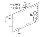
また本発明の一態様では、前記検出部は、前記画像投射装置が前記投射面に対してキャリブレーション用画面の画像を投射した後に、前記検出領域での前記対象物の位置情報を検出し、前記光学式検出装置は、検出された前記対象物の位置情報を、前記画像投射装置又は前記画像投射装置を制御する情報処理装置に対して送信してもよい。 In one aspect of the present invention, the detection unit detects position information of the object in the detection region after the image projection device projects an image of a calibration screen onto the projection surface, The optical detection device may transmit the detected position information of the object to the image projection device or an information processing device that controls the image projection device.
このようにすれば、例えばユーザーが、投射面に投射されたキャリブレーション用画面の画像を見ながら、キャリブレーション用画面の指示にしたがった動作を行うと、ユーザーの指又はタッチペン等の対象物の位置情報が検出される。そして、検出された位置情報が、画像投射装置又は情報処理装置に送信されるようになる。従って、キャリブレーション用画面の画像の投射時における対象物の位置情報を用いて、キャリブレーション処理を実行できるようになり、光学式検出装置の検出精度等の向上を実現できる。 In this way, for example, when the user performs an operation according to the instruction on the calibration screen while viewing the image of the calibration screen projected on the projection surface, the user's finger or a touch pen or other object Location information is detected. Then, the detected position information is transmitted to the image projection apparatus or the information processing apparatus. Therefore, the calibration process can be executed using the position information of the object at the time of projecting the image on the calibration screen, and the detection accuracy and the like of the optical detection device can be improved.
また本発明の一態様では、前記光学式検出装置は、インターフェース部を含み、前記光学式検出装置は、前記インターフェース部を介してキャリブレーション用情報を送信してもよい。 In the aspect of the invention, the optical detection device may include an interface unit, and the optical detection device may transmit calibration information via the interface unit.
このようにすれば、光学式検出装置が、例えばキャリブレーション用プログラムやキャリブレーション時の検出位置情報などのキャリブレーション用情報を、インターフェース部を介して画像投射装置や画像投射装置を制御する情報処理装置等に送信できるようになる。これにより、キャリブレーション処理を効率的に実行することが可能になる。 In this way, the optical detection apparatus controls the image projection apparatus and the image projection apparatus via the interface with the calibration information such as the calibration program and the detected position information at the time of calibration. It becomes possible to transmit to the device. As a result, the calibration process can be executed efficiently.
また本発明の一態様では、前記光学式検出装置は、前記インターフェース部を介して前記画像投射装置から電源を受電してもよい。 In the aspect of the invention, the optical detection device may receive power from the image projection device via the interface unit.
このようにすれば、光学式検出装置は、画像投射装置とのインターフェース処理を行うインターフェース部を有効活用して、画像投射装置から電源が供給されて動作できるようになる。 In this way, the optical detection device can operate by effectively using the interface unit that performs interface processing with the image projection device, by supplying power from the image projection device.
また本発明の他の態様は、上記のいずれかに記載の取り付け装置と、前記取り付け装置に取り付けられた前記画像投射装置とを含む投写型表示装置に関係する。 According to another aspect of the present invention, there is provided a projection display device including any of the above-described attachment devices and the image projection device attached to the attachment device.
以下、本発明の好適な実施の形態について詳細に説明する。なお以下に説明する本実施形態は特許請求の範囲に記載された本発明の内容を不当に限定するものではなく、本実施形態で説明される構成の全てが本発明の解決手段として必須であるとは限らない。 Hereinafter, preferred embodiments of the present invention will be described in detail. The present embodiment described below does not unduly limit the contents of the present invention described in the claims, and all the configurations described in the present embodiment are indispensable as means for solving the present invention. Not necessarily.
1.取り付け装置の構成
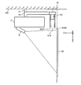
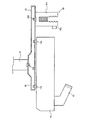
図1に本実施形態の取り付け装置及びこの取り付け装置に取り付けられた画像投射装置10を含む投写型表示装置の構成例を示す。図1は本実施形態の取り付け装置(狭義には天吊り金具)を、液晶プロジェクター或いはデジタル・マイクロミラー・デバイスと呼ばれる画像投射装置10の取り付け装置として使用した場合の例である。そして、この取り付け装置と、この取り付け装置に取り付けられた画像投射装置10により、投写型表示装置が構成される。なお図1では、互いに交差(直交)する軸をX軸、Y軸、Z軸(広義には第1、第2、第3の座標軸)としている。具体的には、画像投射装置10が画像を投射する投射面22(スクリーン)に平行な面がX軸、Y軸により規定されるXY平面になり、XY平面に交差(直交)する方向がZ軸の方向になる。
1. Configuration of Mounting Device FIG. 1 shows a configuration example of a projection type display device including the mounting device of the present embodiment and an
画像投射装置10は、投射レンズなどの光学系を有する投射部12から、スクリーンや壁などの投射面22に向けて画像表示光を拡大投射する。具体的には画像投射装置10は、カラー画像の表示光を生成して、投射部12を介して投射面22に向けて出射する。これにより投射面22にカラー画像が表示されるようになる。
The
図1に示す本実施形態の取り付け装置(天吊り金具)は、第1、第2、第3の取り付け部31、32、33を有する。
The attachment device (ceiling bracket) of the present embodiment shown in FIG. 1 has first, second, and
第1の取り付け部31(第1のブラケット、第1の固定用部材)は、天井400(広義には取り付け対象)に対して取り付け装置を取り付けるためのものであり、例えば天井400に取り付け装置を固定するための部材(金具)である。この取り付け部31は、例えばベースとなる金具や、天井400に取り付け装置を固定するための取り付け用金具(ネジ、ネジ受け)などにより構成される。
The first attachment portion 31 (first bracket, first fixing member) is for attaching an attachment device to the ceiling 400 (attachment target in a broad sense). For example, the attachment device is attached to the
第2の取り付け部32(第2のブラケット、第2の固定用部材)は、投射面22に画像を投射する画像投射装置10(広義には画像生成装置、電子機器)を取り付けるためのものであり、例えば取り付け装置に画像投射装置10を固定するための部材(金具)である。この取り付け部32は、例えばベースとなる金具や、取り付け装置に画像投射装置10を固定するための取り付け用金具などにより構成される。
The second attachment portion 32 (second bracket, second fixing member) is for attaching the image projection device 10 (an image generation device or an electronic device in a broad sense) that projects an image on the
第3の取り付け部33(第3のブラケット、第3の固定用部材)は、光学式検出装置40を取り付けるためのものであり、例えば取り付け装置に光学式検出装置40を固定するための部材(金具)である。この取り付け部33は、例えばベースとなる金具や、取り付け装置に光学式検出装置40を固定するための取り付け用金具などにより構成される。
The third attachment portion 33 (third bracket, third fixing member) is for attaching the
なお、取り付け部31、32、33は一体となって形成されるものであってよい。例えば取り付け部32と取り付け部33のベース金具は、一体となった同じ金具であってもよいし、連結部(ジョイント)により連結される金具であってもよい。また光学式検出装置40は、取り付け装置に対して着脱自在になっていてもよいし、着脱できないように固定化されるものであってもよい。
Note that the
光学式検出装置40は、検出領域RDETにおいて対象物OBを光学的に検出する装置である。例えば図1に示すように、検出領域RDETは、投射面22(表示領域)に沿って設定される領域である。具体的には検出領域RDETは、投射面22(スクリーン)のZ方向側(ユーザー側)において、XY平面に沿って設定される領域である。
The
そして光学式検出装置40は、投射面22の前方側(Z方向側)に設定された検出領域RDETにおいて、ユーザーの指やタッチペンなどの対象物OBを光学的に検出する。このために光学式検出装置40は、図示しない照射部と受光部と検出部を含む。照射部は、検出領域RDETに対して対象物OBの検出用の照射光を出射する。例えば照射部は、検出領域RDETの各位置に応じて強度(照度)が異なる照射光を出射する。受光部は、照射光が指やタッチペンなどの対象物OBに反射されることによる反射光を受光する。この受光部RUは、例えばフォトダイオードやフォトトランジスターなどの受光素子により実現される。検出部は、受光部での受光結果に基づいて、対象物OBの位置情報を検出する。対象物OBの位置情報は、例えば対象物OBのX、Y座標或いはZ座標などである。或いは対象物OBの位置する方向であってもよい。
The
以上のように本実施形態では、天井400等の取り付け対象に画像投射装置10を取り付けるための取り付け装置に対して、光学式検出装置40を取り付けるための取り付け部33を設けている。このようにすれば、光学式検出装置40をオプションユニットとして取り付けることが可能になり、ユーザー側の選択の幅を広げることが可能になる。また光学式検出装置40を取り付けることで、画像投射装置10により映し出されたコンテンツに対するインタラクティブなユーザーインターフェースを提供できるようになる。例えばユーザーは、プレゼン資料の画像を画像投射装置10により投射面22に映しながら、画像内の表示物を、指やタッチペンなどで指示することが可能になり、これまでにないユーザーインターフェースを実現できる。
As described above, in the present embodiment, the
また例えば本実施形態の比較例となる第1の手法として、光学式検出装置40を、画像投射装置10(プロジェクター)の筐体(ケース)に内蔵させる手法も考えられる。
For example, as a first method serving as a comparative example of the present embodiment, a method of incorporating the
しかしながら、この第1の手法によると、画像投射装置10の筐体が大きくなってしまい、コスト増等を招く。また光学式検出装置40を必要とするユーザーと必要としないユーザーの両方に対応することが難しくなる。
However, according to this first method, the housing of the
この点、本実施形態によれば、図1に示すように光学式検出装置40は画像投射装置10の外部に設けられるようになるため、上記のように画像投射装置10の筐体が大きくなってしまう問題を回避できる。また光学式検出装置40を必要とするユーザーに対しては、取り付け装置に光学式検出装置40を取り付けることで、これに対応できる。一方、光学式検出装置40を必要としないユーザーに対しては、取り付け装置から光学式検出装置40を取り外したり、取り付け装置に光学式検出装置40を取り付けないことで、これに対応できる。
In this regard, according to the present embodiment, as shown in FIG. 1, the
また本実施形態の比較例となる第2の手法として、ユーザーが任意の場所に光学式検出装置40を取り付けられるようにする手法も考えられる。
Further, as a second method that is a comparative example of the present embodiment, a method that allows the user to attach the
しかしながら、この第2の手法では、後述するように光学式検出装置40の設置場所によっては、その検出精度を確保できなくなる事態が生じる。また、天井400等にユーザーが光学式検出装置40を別途の作業で取り付けるのは、ユーザーにとって手間である。
However, in the second method, as will be described later, depending on the installation location of the
この点、本実施形態によれば、図1のような取り付け装置を用いることで、画像投射装置10と光学式検出装置40との間の位置関係が固定される。従って、後述するように画像投射装置10の放熱部を避けた領域に光学式検出装置40を固定配置したり、検出精度を悪化させる入射光を制限する入射光制限部を設けることなどが可能になり、光学式検出装置40の検出精度等を確保するのが容易になる。また取り付け装置により画像投射装置10を天井400に取り付ける作業の際に、光学式検出装置40も一体となって取り付けることが可能になる。従って、ユーザーの作業の手間が別途に増えてしまう事態を防止でき、ユーザーの利便性を向上できる。
In this regard, according to the present embodiment, the positional relationship between the
2.放熱による検出位置ズレ
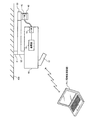
画像投射装置10では、図2に示すように筺体の内部に溜まった熱を放熱するための放熱部14が設けられている。具体的には、筺体内部の空気を排出するためのファンや排気口が放熱部14として設けられている。
2. Detection position shift due to heat dissipation The
しかしながら、このファン等の放熱部14からの熱風があたる場所に、光学式検出装置40が設置されると、光学式検出装置40が有する素子(受光素子、発光素子、トランジスター等)の特性の温度依存性等により、対象物OBの検出位置のズレが生じるおそれがある。例えば上述の第2の手法のように、ユーザーが任意の場所に光学式検出装置40を設置する手法では、設置位置に応じて検出位置のズレが変動してしまい、その調整が困難になる。また画像投射装置10の放熱部14からの放熱の状態は、時間に応じて変化するため、例えば放熱が頻繁に行われる期間と、放熱があまり行われない期間とで、検出位置のズレが変動してしまう。
However, when the
そこで本実施形態の取り付け装置では図2に示すように、画像投射装置10が熱を外部に放熱するための放熱部14を有する場合に、光学式検出装置40は、取り付け部33により、放熱部14を避けた領域に取り付けられる。例えば放熱部14を避けた領域に取り付け部33が設けられ、この取り付け部33により光学式検出装置40が取り付けられる。
Therefore, in the mounting device of the present embodiment, as shown in FIG. 2, when the
具体的には図2では画像投射装置10の後方側(投射面22と反対側)に放熱部14が設けられている。このため、光学式検出装置40は、取り付け装置の取り付け部33により、画像投射装置10の前方側(投射面22側)に取り付けられる。即ち放熱部14であるファンからの熱風が光学式検出装置40にあたりにくくなる場所に、取り付け部33が設けられる。
Specifically, in FIG. 2, the
このように、取り付け部33により、放熱部14(放熱部からの熱)を避けた領域に光学式検出装置40を取り付ければ、放熱部14からの熱を原因とする検出位置のズレの問題を解消できる。
In this way, if the
特に本実施形態では、取り付け装置を介して画像投射装置10と光学式検出装置40の位置関係が固定されることに着目している。このように位置関係が固定していることを利用することで、放熱部14からの熱を避けた領域に光学式検出装置40を配置できるようになり、位置検出のズレの問題を効果的に抑止できるようになる。
In particular, in this embodiment, attention is paid to the fact that the positional relationship between the
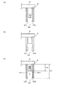
なお、本実施形態では、放熱部14を避けた領域に光学式検出装置40(取り付け部33)を設けているが、この放熱部14を避けた領域の例を図3(A)〜図3(C)に示す。
In this embodiment, the optical detection device 40 (attachment portion 33) is provided in a region where the
例えば図3(A)では、画像投射装置10(筺体)の後方面に放熱部14が設けられている。この場合には、例えば画像投射装置10の左側面、右側面、前方面に対向する位置に光学式検出装置40が取り付けられる。
For example, in FIG. 3A, a
また図3(B)では、画像投射装置10の前方面に放熱部14が設けられている。この場合には、画像投射装置10の左側面、右側面、後方面に対向する位置に光学式検出装置40が取り付けられる。
In FIG. 3B, a
また図3(C)では、画像投射装置10の左側面に放熱部14が設けられている。この場合には、画像投射装置10の右側面、前方面、後方面に対向する位置に光学式検出装置40が取り付けられる。
In FIG. 3C, a
このように本実施形態では、画像投射装置10の前方面、後方面、左側面、右側面のいずれか1つの面に放熱部14が設けられている場合に、この1つの面以外の面に対向する位置に光学式検出装置40が取り付けられる。このようにすることで、放熱部14を避けた領域への光学式検出装置40の取り付けが実現される。
As described above, in the present embodiment, when the
3.反射光による検出位置ズレ
図4(A)では、例えば単焦点型の画像投射装置10が取り付け装置により天井400に取り付けられている。そして、この画像投射装置10から投射された投射光が、スクリーン等の投射面22で反射され、反射された光に含まれる赤外光が、光学式検出装置40に入射されている。このように、ユーザーの指やタッチペンなどの対象物からの反射光以外の光が、光学式検出装置40の受光素子に入射されると、検出位置のズレが発生するおそれがある。特に、図1に示すように光学式検出装置40の検出領域RDETは、投射面22の直ぐ近くの前方領域に設定されるため、投射面22で反射された光が光学式検出装置40に入射される可能性が高い。
3. Detection position deviation due to reflected light In FIG. 4A, for example, a single-focus
また図4(B)では、画像投射装置10と投射面22の壁の間に光学式検出装置40が取り付けられている。そして、光学式検出装置40が出射した照射光が画像投射装置10の筺体で反射され、その反射光が光学式検出装置40に入射されている。また光学式検出装置40からの照射光が、投射面22(壁)に反射され、その反射光が光学式検出装置40に入射されている。このような場合にも、光学式検出装置40の受光素子に入射されるデフォルト光のレベルが変化して、検出位置のズレが発生するおそれがある。
In FIG. 4B, an
そこで本実施形態では、このような検出領域RDETの面(XY平面)に交差する入射方向の光が光学式検出装置40に入射されるのを規制する入射光規制部を設ける。具体的には図5に示すように、検出領域RDETの面(XY平面)に沿った方向(投射面に平行な方向)のスリット面を有する入射光用スリットSLBを設ける。例えば図5の入射光用スリットSLBは、光学式検出装置40を挟むように設けられる第1のスリット面SLB1及び第2のスリット面SLB2を有する。
Therefore, in the present embodiment, an incident light restricting unit that restricts the incident light that intersects the surface (XY plane) of the detection region RDET from entering the
このような入射光用スリットSLB等で実現される入射光規制部は、図4(A)のように画像投射装置10からの投射光が投射面22で反射されることによる反射光が、光学式検出装置40に入射されるのを規制(制限)する。或いは図4(B)のように光学式検出装置40からの照射光が投射面22又は画像投射装置10で反射されることによる反射光が、光学式検出装置40に入射されるのを規制(制限)する。即ち、入射光制限部は、図4(A)、図4(B)のような反射光が光学式検出装置40に入射されるのを規制するような形状や配置の部材により形成される。
The incident light restricting section realized by such an incident light slit SLB is such that the reflected light from the projection light from the
このような入射光用スリットSLB等の入射光規制部を設ければ、図4(A)、図4(B)のような反射光の入射を原因とする検出位置のズレを抑止して、光学式検出装置40の検出精度を確保できるようになる。
By providing such an incident light restricting portion such as the incident light slit SLB, the deviation of the detection position caused by the incidence of the reflected light as shown in FIGS. 4A and 4B is suppressed. The detection accuracy of the
特に本実施形態の取り付け装置によれば、画像投射装置10と光学式検出装置40が一体的に取り付けられるため、これらの装置の位置関係は固定化される。従って、このような固定化された位置関係を前提とすれば、画像投射装置10等からの反射光が光学式検出装置40に入射されるのを防止する入射光制限部の形状や配置の設定を容易化できるという利点がある。即ち、前述のように光学式検出装置40をユーザーが任意の場所に設定する比較例の手法では、様々な場所に光学式検出装置40が設置されても対応できるように入射光規制部を設ける必要があり、入射光規制部の形状や配置の設定が難しくなる。これに対して本実施形態の取り付け装置によれば、画像投射装置10と光学式検出装置40の位置関係が固定化されているため、例えば図5のような形状や配置の入射光用スリットSLBを設けるだけで対応できるという利点がある。
In particular, according to the attachment device of the present embodiment, the
更に本実施形態では図6(A)に示すように、スリット面SLB1、SLB2に対して反射防止層(反射防止膜)RPL1、RPL2を設けることが望ましい。例えばスリット面SLB1、SLB2に無反射コーティングを施すことで反射防止層RPL1、RPL2を形成する。このようにすれば、スリット面SLB1、SLB2で反射した光が光学式検出装置40の受光素子に入射されるのを規制できるようになり、光学式検出装置40の検出精度等の悪化を抑止できる。
Furthermore, in this embodiment, as shown in FIG. 6A, it is desirable to provide antireflection layers (antireflection films) RPL1 and RPL2 on the slit surfaces SLB1 and SLB2. For example, the antireflection layers RPL1 and RPL2 are formed by applying an antireflection coating to the slit surfaces SLB1 and SLB2. If it does in this way, it will become possible to control now that the light reflected by slit surface SLB1 and SLB2 will enter into the photo acceptance unit of
なお反射防止層RPL1、RPL2の代わりに、図6(B)に示すように、スリット面SLB1、SLB2に対して凹部を設けてもよい。即ち図5では、スリット面SLB1、SLB2は平らな形状になっているが、図6(B)では、スリット面SLB1、SLB2は平らな形状になっておらず、くぼみが形成されている。このような凹部を設けることでスリット面SLB1、SLB2での表面反射を抑制することが可能になる。これにより、光学式検出装置40の受光素子に対して不要な反射光が入射されるのを規制できるようになり、光学式検出装置40の検出精度等の悪化を抑止できる。
Instead of the antireflection layers RPL1 and RPL2, as shown in FIG. 6B, recesses may be provided on the slit surfaces SLB1 and SLB2. That is, in FIG. 5, the slit surfaces SLB1 and SLB2 are flat, but in FIG. 6B, the slit surfaces SLB1 and SLB2 are not flat and a recess is formed. By providing such a recess, it is possible to suppress surface reflection at the slit surfaces SLB1 and SLB2. As a result, it is possible to restrict unnecessary reflected light from being incident on the light receiving element of the
また図6(C)では、後述するように光学式検出装置40が照射光用スリットSL(照射方向規制部)を有している。この照射光用スリットSLは、光学式検出装置40から出射される対象物の検出用の照射光を、図1の検出領域RDETの面(XY平面)に沿った方向(投射面に平行な方向)に規制するものであり、第1、第2のスリット面SFL1、SFL2を有する。このような照射光用スリットSLを設けることで、光学式検出装置40から照射される照射光の照射方向を、検出領域RDETの面に沿った方向に規制できるようになる。従って、検出領域RDETへの照射光が、図1のZ方向に広がってしまう事態を防止でき、ユーザーの体がスクリーン20に近づいた場合に、ユーザーの体を指やタッチペンなどの対象物であると誤検出してしまう事態を防止できる。
In FIG. 6C, the
そして図6(C)において、取り付け部33から入射光用スリットSLBの端部までの高さをHS1とし、取り付け部33から照射光用スリットSLの端部までの高さをHS2とする。すると図6(C)では、HS1>HS2の関係が成り立っている。即ち、入射光用スリットSLBの方が、照射光用スリットSLよりも、そのスリット高さが高くなっている。
In FIG. 6C, the height from the
このようにすれば、光学式検出装置40からの照射光の方向は、照射光用スリットSLにより、検出領域RDETの面に沿った方向に規制されるようになる。またZ方向に照射方向がずれた照射光についても、入射光用スリットSLBが存在することにより、図4(B)のように画像投射装置10や投射面22の方に出射されるのが規制され、画像投射装置10や投射面22での反射光が光学式検出装置40に入射されるのを規制できるようになる。従って、これらの反射光の入射を原因とする検出精度等の悪化を抑止できる。
In this way, the direction of the irradiation light from the
なお、以上では、本実施形態の取り付け装置により、画像投射装置10と投射面22の間に光学式検出装置40が取り付けられる場合について主に説明したが、本実施形態はこれに限定されない。例えば図7の変形例に示すように、画像投射装置10の後方側(投射面の反対側)に、取り付け部33を設けて光学式検出装置40を取り付けるようにしてもよい。例えば、投射面22までの距離が8cm〜20cmというような短い距離でも、投射面22に対して大きなサイズの画像を映し出せるような単焦点型の画像投射装置10では、図7に示すような位置に光学式検出装置40を設けることが望ましい。
In addition, although the case where the
そして、この場合には、例えば図7に示すような板状の入射光制限部SLCを、画像投射装置10と光学式検出装置40の間に設ければよい。このような入射光制限部SLCを設ければ、画像投射装置10からの投射光が投射面22等で反射されて、光学式検出装置40に入射されてしまうのを抑止できる。或いは、光学式検出装置40からの照射光が、画像投射装置10や投射面22で反射されて、光学式検出装置40に入射され、デフォルト光のレベルが上昇してしまう事態も抑止できる。これにより光学式検出装置40の位置検出の精度を維持できるようになる。
In this case, for example, a plate-like incident light limiting unit SLC as shown in FIG. 7 may be provided between the
4.光学式検出装置の構成
次に光学式検出装置の構成例について説明する。図8の光学式検出装置は、照射部EUと受光部RUと検出部50を含む。また制御部60を含むことができる。
4). Configuration of Optical Detection Device Next, a configuration example of the optical detection device will be described. The optical detection device in FIG. 8 includes an irradiation unit EU, a light receiving unit RU, and a
照射部EUは、対象物を検出するための照射光(検出光)を出射する。具体的には、照射方向に応じて強度(照度)が異なる照射光を放射状に出射する。これにより検出領域RDET(図1参照)には、照射方向に応じて強度が異なる照射光強度分布が形成される。 The irradiation unit EU emits irradiation light (detection light) for detecting an object. Specifically, irradiation light having different intensities (illuminance) according to the irradiation direction is emitted radially. Thereby, in the detection region RDET (see FIG. 1), an irradiation light intensity distribution having different intensities depending on the irradiation direction is formed.
受光部RUは、照射部EUからの照射光が対象物に反射されることによる反射光を受光する。この受光部RUは、例えばフォトダイオードやフォトトランジスターなどの受光素子により実現できる。この受光部RUには検出部50が例えば電気的に接続されている。
The light receiving unit RU receives reflected light resulting from reflection of irradiation light from the irradiation unit EU on an object. The light receiving unit RU can be realized by a light receiving element such as a photodiode or a phototransistor. For example, a
検出部50は、受光部RUでの受光結果に基づいて、少なくとも対象物の位置する方向等を検出する。この検出部の機能は、アナログ回路等を有する集積回路装置や、マイクロコンピュータ上で動作するソフトウェア(プログラム)などにより実現できる。例えば検出部は、受光部の受光素子が対象物からの反射光を受光することで発生した検出電流を、検出電圧に変換し、受光結果である検出電圧に基づいて、対象物の位置や方向等を検出する。
The
具体的には検出部50は、受光部RUでの受光結果(受光信号)に基づいて、対象物までの距離(照射部の配置位置からの距離)を検出する。そして検出された距離と、検出された対象物の方向(存在方向)とに基づいて、対象物の位置を検出する。例えば検出領域RDETのXY平面でのX、Y座標を検出する。なお、X軸方向に沿って所与の距離だけ離れた第1、第2の照射部を設けるようにしてもよい。この場合には、第1の照射部からの第1の照射光が対象物に反射されることによる第1の反射光の受光結果に基づいて、第1の照射部に対する対象物の方向を第1の方向として検出する。また第2の照射部からの第2の照射光が対象物に反射されることによる第2の反射光の受光結果に基づいて、第2の照射部に対する対象物の方向を第2の方向として検出する。そして検出された第1、第2の方向と、第1、第2の照射部間の距離とに基づいて、対象物の位置を検出すればよい。
Specifically, the
制御部60は光学式検出装置の各種の制御処理を行う。具体的には照射部EUが有する光源部の発光制御などを行う。この制御部60は照射部EU、検出部50に電気的に接続されている。制御部60の機能は、集積回路装置やマイクロコンピュータ上で動作するソフトウェアなどにより実現できる。例えば制御部60は、照射部EUが第1、第2の光源部を含む場合に、これらの第1、第2の光源部を交互に発光させる制御を行う。また、前述のように第1、第2の照射部が設けられる場合には、第1の照射部に対する対象物の方向を求める第1の期間において、第1の照射部に設けられる第1、第2の光源部を交互に発光させる制御を行う。また第2の照射部に対する対象物の方向を求める第2の期間において、第2の照射部に設けられる第3、第4の光源部を交互に発光させる制御を行う。
The
5.対象物の検出手法
次に本実施形態による対象物の検出手法について詳細に説明する。
5). Object Detection Method Next, the object detection method according to the present embodiment will be described in detail.
図9(A)に示すように本実施形態の光学式検出装置(照射部)は、光源部LS1と、ライトガイドLGと、照射方向設定部LEを含む。また反射シートRSを含む。そして照射方向設定部LEは光学シートPS及びルーバーフィルムLFを含む。なお、これらの構成要素の一部を省略したり、他の構成要素を追加するなどの種々の変形実施が可能である。 As shown in FIG. 9A, the optical detection device (irradiation unit) of the present embodiment includes a light source unit LS1, a light guide LG, and an irradiation direction setting unit LE. Moreover, the reflective sheet RS is included. The irradiation direction setting unit LE includes the optical sheet PS and the louver film LF. Various modifications such as omitting some of these components or adding other components are possible.
光源部LS1は、光源光を出射するものであり、LED(発光ダイオード)等の発光素子を有する。この光源部LS1は例えば赤外光(可視光領域に近い近赤外線)の光源光を放出する。即ち、光源部LS1が発光する光源光は、ユーザーの指やタッチペン等の対象物により効率的に反射される波長帯域の光や、外乱光となる環境光にあまり含まれない波長帯域の光であることが望ましい。具体的には、人体の表面での反射率が高い波長帯域の光である850nm付近の波長の赤外光や、環境光にあまり含まれない波長帯域の光である950nm付近の赤外光などである。 The light source unit LS1 emits light from a light source and includes a light emitting element such as an LED (light emitting diode). The light source unit LS1 emits, for example, infrared light (near infrared light close to the visible light region). That is, the light source light emitted from the light source unit LS1 is light in a wavelength band that is efficiently reflected by an object such as a user's finger or a touch pen, or light in a wavelength band that is not so much included in ambient light that becomes disturbance light. It is desirable to be. Specifically, infrared light with a wavelength near 850 nm, which is light in a wavelength band with high reflectance on the surface of the human body, infrared light near 950 nm, which is light in a wavelength band that is not so much included in environmental light, etc. It is.
ライトガイドLG(導光部材)は、光源部LS1が発光した光源光を導光するものである。例えばライトガイドLGは、光源部LS1からの光源光を曲線状の導光経路に沿って導光し、その形状は曲線形状になっている。具体的には図9(A)ではライガイドLGは円弧形状になっている。なお図9(A)ではライトガイドLGはその中心角が180度の円弧形状になっているが、中心角が180度よりも小さい円弧形状であってもよい。ライトガイドLGは、例えばアクリル樹脂やポリカーボネートなどの透明な樹脂部材等により形成される。そして光源部LS1からの光源光は、ライトガイドLGの一端側(図9(A)では左側)の光入射面に入射される。 The light guide LG (light guide member) guides the light source light emitted from the light source unit LS1. For example, the light guide LG guides the light source light from the light source unit LS1 along a curved light guide path, and the shape thereof is a curved shape. Specifically, in FIG. 9A, the lie guide LG has an arc shape. In FIG. 9A, the light guide LG has an arc shape with a center angle of 180 degrees, but may have an arc shape with a center angle smaller than 180 degrees. The light guide LG is formed of, for example, a transparent resin member such as acrylic resin or polycarbonate. The light source light from the light source unit LS1 is incident on the light incident surface on one end side (left side in FIG. 9A) of the light guide LG.
ライトガイドLGの外周側(B1に示す側)及び内周側(B2に示す側)の少なくとも一方には、ライトガイドLGからの光源光の出光効率を調整するための加工が施されている。加工手法としては、例えば反射ドットを印刷するシルク印刷方式や、スタンパーやインジェクションで凹凸を付ける成型方式や、溝加工方式などの種々の手法を採用できる。 At least one of the outer peripheral side (the side indicated by B1) and the inner peripheral side (the side indicated by B2) of the light guide LG is processed to adjust the light output efficiency of the light source light from the light guide LG. As a processing method, for example, various methods such as a silk printing method for printing reflective dots, a molding method for forming irregularities with a stamper or injection, and a groove processing method can be adopted.
プリズムシートPSとルーバーフィルムLFにより実現される照射方向設定部LE(照射光出射部)は、ライトガイドLGの外周側に設けられ、ライトガイドLGの外周側(外周面)から出射される光源光を受ける。そして曲線形状(円弧形状)のライトガイドLGの内周側(B2)から外周側(B1)へと向かう方向に照射方向が設定された照射光LTを出射する。即ち、ライトガイドLGの外周側から出射される光源光の方向を、ライトガイドLGの例えば法線方向(半径方向)に沿った照射方向に設定(規制)する。これにより、ライトガイドLGの内周側から外周側に向かう方向に、照射光LTが放射状に出射されるようになる。 The irradiation direction setting unit LE (irradiation light emitting unit) realized by the prism sheet PS and the louver film LF is provided on the outer peripheral side of the light guide LG, and is emitted from the outer peripheral side (outer peripheral surface) of the light guide LG. Receive. And the irradiation light LT by which the irradiation direction was set to the direction which goes to an outer peripheral side (B1) from the inner peripheral side (B2) of the light guide LG of curved shape (arc shape) is radiate | emitted. That is, the direction of the light source light emitted from the outer peripheral side of the light guide LG is set (restricted) to an irradiation direction along, for example, the normal direction (radial direction) of the light guide LG. As a result, the irradiation light LT is emitted radially in a direction from the inner peripheral side to the outer peripheral side of the light guide LG.
このような照射光LTの照射方向の設定は、照射方向設定部LEのプリズムシートPSやルーバーフィルムLFなどにより実現される。例えばプリズムシートPSは、ライトガイドLGの外周側から低視角で出射される光源光の方向を、法線方向側に立ち上げて、出光特性のピークが法線方向になるように設定する。またルーバーフィルムLFは、法線方向以外の方向の光(低視角光)を遮光(カット)する。なお、照射方向設定部LEに拡散シート等を設けてよい。また反射シートRSは、ライトガイドLGの内周側に設けられる。このように反射シートRSを内周側に設けることで、外周側への光源光の出光効率を改善できる。 Such setting of the irradiation direction of the irradiation light LT is realized by the prism sheet PS or the louver film LF of the irradiation direction setting unit LE. For example, the prism sheet PS sets the direction of the light source light emitted at a low viewing angle from the outer peripheral side of the light guide LG to the normal direction side so that the peak of the light emission characteristic is in the normal direction. The louver film LF blocks (cuts) light in a direction other than the normal direction (low viewing angle light). In addition, you may provide a diffusion sheet etc. in the irradiation direction setting part LE. The reflection sheet RS is provided on the inner peripheral side of the light guide LG. Thus, the light emission efficiency of the light source light to the outer peripheral side can be improved by providing the reflection sheet RS on the inner peripheral side.
そして図9(A)に示すように、光源部LS1が、ライトガイドLGの一端側(B3)の光入射面に対して光源光を出射することで、第1の照射光強度分布LID1が対象物の検出領域に形成される。この第1の照射光強度分布LID1は、ライトガイドLGの一端側(B3)から他端側(B4)に向かうにつれて照射光の強度が低くなる強度分布である。即ち図9(A)において照射光LTのベクトルの大きさが強度(照度)を表しており、ライトガイドLGの一端側(B3)では照射光LTの強度は最も大きく、他端側(B4)では強度は最も小さい。そしてライトガイドLGの一端側から他端側に向かうにつれて、照射光LTの強度は単調減少している。 Then, as shown in FIG. 9A, the light source unit LS1 emits light source light to the light incident surface on one end side (B3) of the light guide LG, so that the first irradiation light intensity distribution LID1 is targeted. It is formed in the object detection area. The first irradiation light intensity distribution LID1 is an intensity distribution in which the intensity of irradiation light decreases from one end side (B3) to the other end side (B4) of the light guide LG. That is, in FIG. 9A, the magnitude of the vector of the irradiation light LT represents the intensity (illuminance), and the intensity of the irradiation light LT is the highest on one end side (B3) of the light guide LG and the other end side (B4). Then the intensity is the smallest. And the intensity | strength of irradiation light LT is decreasing monotonously as it goes to the other end side from the one end side of the light guide LG.
一方、図9(B)に示すように、第2の光源部LS2が、ライトガイドLGの他端側(B4)の光入射面に対して第2の光源光を出射することで、第2の照射光強度分布LID2が検出領域に形成される。この第2の照射光強度分布LID2は、第1の照射光強度分布LID1とは強度分布が異なり、ライトガイドLGの他端側(B4)から一端側(B3)に向かうにつれて照射光の強度が低くなる強度分布である。即ち図9(B)では、ライトガイドLGの他端側では照射光LTの強度は最も大きく、一端側では強度は最も小さい。そして他端側から一端側に向かうにつれて、照射光LTの強度は単調減少している。 On the other hand, as shown in FIG. 9B, the second light source unit LS2 emits the second light source light to the light incident surface on the other end side (B4) of the light guide LG, whereby the second light source unit LS2 emits the second light source light. The irradiation light intensity distribution LID2 is formed in the detection region. This second irradiation light intensity distribution LID2 is different in intensity distribution from the first irradiation light intensity distribution LID1, and the intensity of irradiation light increases from the other end side (B4) to the one end side (B3) of the light guide LG. The intensity distribution is lowered. That is, in FIG. 9B, the intensity of the irradiation light LT is the highest on the other end side of the light guide LG, and the intensity is the lowest on the one end side. Then, the intensity of the irradiation light LT monotonously decreases from the other end side toward the one end side.
このような照射光強度分布LID1、LID2を形成し、これらの強度分布の照射光による対象物の反射光を受光することで、環境光などの外乱光の影響を最小限に抑えた、より精度の高い対象物の検出が可能になる。即ち、外乱光に含まれる赤外成分を相殺することが可能になり、この赤外成分が対象物の検出に及ぼす悪影響を最小限に抑えることが可能になる。 By forming such irradiation light intensity distributions LID1 and LID2 and receiving the reflected light of the object by the irradiation light of these intensity distributions, the influence of ambient light such as ambient light is minimized. It is possible to detect an object having a high height. That is, it is possible to cancel out the infrared component included in the disturbance light, and it is possible to minimize the adverse effect of the infrared component on the detection of the object.
例えば図10(A)のE1は、図9(A)の照射光強度分布LID1において、照射光LTの照射方向の角度と、その角度での照射光LTの強度との関係を示す図である。図10(A)のE1では、照射方向が図10(B)のDD1の方向(左方向)である場合に強度が最も高くなる。一方、DD3の方向(右方向)である場合に強度が最も低くなり、DD2の方向ではその中間の強度になる。具体的には方向DD1から方向DD3への角度変化に対して照射光の強度は単調減少しており、例えばリニア(直線的)に変化している。なお図10(B)では、ライトガイドLGの円弧形状の中心位置が、光学式検出装置の配置位置PEになっている。 For example, E1 in FIG. 10 (A) is a diagram showing the relationship between the angle of the irradiation direction of the irradiation light LT and the intensity of the irradiation light LT at that angle in the irradiation light intensity distribution LID1 in FIG. 9 (A). . At E1 in FIG. 10A, the intensity is highest when the irradiation direction is the direction DD1 in FIG. 10B (left direction). On the other hand, the intensity is lowest when the direction is DD3 (right direction), and the intensity is intermediate in the direction DD2. Specifically, the intensity of the irradiation light monotonously decreases with respect to the angle change from the direction DD1 to the direction DD3, for example, changes linearly (linearly). In FIG. 10B, the center position of the arc shape of the light guide LG is the arrangement position PE of the optical detection device.
また図10(A)のE2は、図9(B)の照射光強度分布LID2において、照射光LTの照射方向の角度と、その角度での照射光LTの強度との関係を示す図である。図10(A)のE2では、照射方向が図10(B)のDD3の方向である場合に強度が最も高くなる。一方、DD1の方向である場合に強度が最も低くなり、DD2の方向ではその中間の強度になる。具体的には方向DD3から方向DD1への角度変化に対して照射光の強度は単調減少しており、例えばリニアに変化している。なお図10(A)では照射方向の角度と強度の関係はリニアな関係になっているが、本実施形態はこれに限定されず、例えば双曲線の関係等であってもよい。 E2 in FIG. 10A is a diagram showing the relationship between the irradiation direction angle of the irradiation light LT and the intensity of the irradiation light LT at that angle in the irradiation light intensity distribution LID2 in FIG. 9B. . In E2 of FIG. 10A, the intensity is highest when the irradiation direction is the direction of DD3 of FIG. On the other hand, the intensity is the lowest in the direction of DD1, and the intermediate intensity in the direction of DD2. Specifically, the intensity of irradiation light monotonously decreases with respect to an angle change from the direction DD3 to the direction DD1, and changes linearly, for example. In FIG. 10A, the relationship between the angle in the irradiation direction and the intensity is a linear relationship, but the present embodiment is not limited to this, and may be a hyperbolic relationship, for example.
そして図10(B)に示すように、角度θの方向DDBに対象物OBが存在したとする。すると、図9(A)のように光源部LS1が発光することで照射光強度分布LID1を形成した場合(E1の場合)には、図10(A)に示すように、DDB(角度θ)の方向に存在する対象物OBの位置での強度はINTaになる。一方、図9(B)のように光源部LS2が発光することで照射光強度分布LID2を形成した場合(E2の場合)には、DDBの方向に存在する対象物OBの位置での強度はINTbになる。 Then, as shown in FIG. 10B, it is assumed that the object OB exists in the direction DDB of the angle θ. Then, when the irradiation light intensity distribution LID1 is formed by the light source LS1 emitting light as shown in FIG. 9A (in the case of E1), as shown in FIG. 10A, DDB (angle θ) The intensity at the position of the object OB existing in the direction is INTa. On the other hand, when the irradiation light intensity distribution LID2 is formed by light emission from the light source unit LS2 as shown in FIG. 9B (in the case of E2), the intensity at the position of the object OB existing in the direction of DDB is INTb.
従って、これらの強度INTa、INTbの関係を求めることで、対象物OBの位置する方向DDB(角度θ)を特定できる。そして例えば後述する図12(A)、図12(B)の手法により光学式検出装置の配置位置PEからの対象物OBの距離を求めれば、求められた距離と方向DDBとに基づいて対象物OBの位置を特定できる。或いは、後述する図13に示すように2個の照射部EU1、EU2を設け、EU1、EU2の各照射部に対する対象物OBの方向DDB1(θ1)、DDB2(θ2)を求めれば、これらの方向DDB1、DDB2と照射部EU1、EU2間の距離DSとにより、対象物OBの位置を特定できる。 Therefore, the direction DDB (angle θ) in which the object OB is located can be specified by obtaining the relationship between the intensities INTa and INTb. For example, if the distance of the object OB from the arrangement position PE of the optical detection device is obtained by the method shown in FIGS. 12A and 12B described later, the object is based on the obtained distance and the direction DDB. The position of OB can be specified. Alternatively, as shown in FIG. 13 to be described later, if two irradiation units EU1 and EU2 are provided and the directions DDB1 (θ1) and DDB2 (θ2) of the object OB with respect to the irradiation units EU1 and EU2 are obtained, these directions are obtained. The position of the object OB can be specified by DDB1 and DDB2 and the distance DS between the irradiation units EU1 and EU2.
このような強度INTa、INTbの関係を求めるために、本実施形態では、図8の受光部RUが、図9(A)のような照射光強度分布LID1を形成した際の対象物OBの反射光(第1の反射光)を受光する。この時の反射光の検出受光量をGaとした場合に、このGaが強度INTaに対応するようになる。また受光部RUが、図9(B)のような照射光強度分布LID2を形成した際の対象物OBの反射光(第2の反射光)を受光する。この時の反射光の検出受光量をGbとした場合に、このGbが強度INTbに対応するようになる。従って、検出受光量GaとGbの関係が求まれば、強度INTa、INTbの関係が求まり、対象物OBの位置する方向DDBを求めることができる。 In order to obtain such a relationship between the intensity INTa and INTb, in this embodiment, the light receiving unit RU of FIG. 8 reflects the object OB when the irradiation light intensity distribution LID1 as shown in FIG. 9A is formed. Light (first reflected light) is received. If the detected light reception amount of the reflected light at this time is Ga, this Ga corresponds to the intensity INTa. The light receiving unit RU receives the reflected light (second reflected light) of the object OB when the irradiation light intensity distribution LID2 as shown in FIG. 9B is formed. When the detected light reception amount of the reflected light at this time is Gb, this Gb corresponds to the intensity INTb. Therefore, if the relationship between the detected light reception amounts Ga and Gb is obtained, the relationship between the intensity INTa and INTb can be obtained, and the direction DDB in which the object OB is located can be obtained.
例えば図9(A)の光源部LS1の制御量(例えば電流量)、変換係数、放出光量を、各々、Ia、k、Eaとする。また図9(B)の光源部LS2の制御量(電流量)、変換係数、放出光量を、各々、Ib、k、Ebとする。すると下式(1)、(2)が成立する。 For example, the control amount (for example, current amount), the conversion coefficient, and the emitted light amount of the light source unit LS1 in FIG. In addition, the control amount (current amount), the conversion coefficient, and the emitted light amount of the light source unit LS2 in FIG. 9B are respectively denoted by Ib, k, and Eb. Then, the following expressions (1) and (2) are established.
Ea=k・Ia (1)
Eb=k・Ib (2)
また光源部LS1からの光源光(第1の光源光)の減衰係数をfaとし、この光源光に対応する反射光(第1の反射光)の検出受光量をGaとする。また光源部LS2からの光源光(第2の光源光)の減衰係数をfbとし、この光源光に対応する反射光(第2の反射光)の検出受光量をGbとする。すると下式(3)、(4)が成立する。
Ea = k · Ia (1)
Eb = k · Ib (2)
Further, let fa be the attenuation coefficient of the light source light (first light source light) from the light source unit LS1, and let Ga be the detected received light amount of the reflected light (first reflected light) corresponding to this light source light. Further, the attenuation coefficient of the light source light (second light source light) from the light source unit LS2 is fb, and the detected light reception amount of the reflected light (second reflected light) corresponding to the light source light is Gb. Then, the following expressions (3) and (4) are established.
Ga=fa・Ea=fa・k・Ia (3)
Gb=fb・Eb=fb・k・Ib (4)
従って、検出受光量Ga、Gbの比は下式(5)のように表せる。
Ga = fa · Ea = fa · k · Ia (3)
Gb = fb · Eb = fb · k · Ib (4)
Therefore, the ratio of the detected light reception amounts Ga and Gb can be expressed as the following equation (5).
Ga/Gb=(fa/fb)・(Ia/Ib) (5)
ここでGa/Gbは、受光部RUでの受光結果から特定することができ、Ia/Ibは、制御部60による照射部EUの制御量から特定することができる。そして図10(A)の強度INTa、INTbと減衰係数fa、fbとは一意の関係にある。例えば減衰係数fa、fbが小さな値となり、減衰量が大きい場合は、強度INTa、INTbが小さいことを意味する。一方、減衰係数fa、fbが大きな値となり、減衰量が小さい場合は、強度INTa、INTbが大きいことを意味する。従って、上式(5)から減衰率の比fa/fbを求めることで、対象物の方向、位置等を求めることが可能になる。
Ga / Gb = (fa / fb). (Ia / Ib) (5)
Here, Ga / Gb can be specified from the light reception result in the light receiving unit RU, and Ia / Ib can be specified from the control amount of the irradiation unit EU by the
より具体的には、一方の制御量IaをImに固定し、検出受光量の比Ga/Gbが1になるように、他方の制御量Ibを制御する。例えば後述する図12(A)のように光源部LS1、LS2を逆相で交互に点灯させる制御を行い、検出受光量の波形を解析し、検出波形が観測されなくなるように(Ga/Gb=1になるように)、他方の制御量Ibを制御する。そして、このときの他方の制御量Ib=Im・(fa/fb)から、減衰係数の比fa/fbを求めて、対象物の方向、位置等を求める。 More specifically, one control amount Ia is fixed to Im, and the other control amount Ib is controlled so that the detected light reception amount ratio Ga / Gb becomes 1. For example, as shown in FIG. 12A, which will be described later, the light sources LS1 and LS2 are controlled to turn on alternately in reverse phase, and the detected received light amount waveform is analyzed so that the detected waveform is not observed (Ga / Gb = The other control amount Ib is controlled. Then, the ratio fa / fb of the attenuation coefficient is obtained from the other control amount Ib = Im · (fa / fb) at this time, and the direction, position, etc. of the object are obtained.
また下式(6)、(7)のように、Ga/Gb=1になると共に制御量IaとIbの和が一定になるように制御してもよい。 Further, as in the following formulas (6) and (7), control may be performed so that Ga / Gb = 1 and the sum of the control amounts Ia and Ib is constant.
Ga/Gb=1 (6)
Im=Ia+Ib (7)
上式(6)、(7)を上式(5)に代入すると下式(8)が成立する。
Ga / Gb = 1 (6)
Im = Ia + Ib (7)
Substituting the above equations (6) and (7) into the above equation (5), the following equation (8) is established.
Ga/Gb=1=(fa/fb)・(Ia/Ib)
=(fa/fb)・{(Im−Ib)/Ib} (8)
上式(8)より、Ibは下式(9)のように表される。
Ga / Gb = 1 = (fa / fb) · (Ia / Ib)
= (Fa / fb) · {(Im−Ib) / Ib} (8)
From the above equation (8), Ib is expressed as the following equation (9).
Ib={fa/(fa+fb)}・Im (9)
ここでα=fa/(fa+fb)とおくと、上式(9)は下式(10)のように表され、減衰係数の比fa/fbは、αを用いて下式(11)のように表される。
Ib = {fa / (fa + fb)} · Im (9)
Here, if α = fa / (fa + fb), the above equation (9) is expressed as the following equation (10), and the attenuation coefficient ratio fa / fb is expressed by the following equation (11) using α. It is expressed in
Ib=α・Im (10)
fa/fb=α/(1−α) (11)
従って、Ga/Gb=1になると共にIaとIbの和が一定値Imになるように制御すれば、そのときのIb、Imから上式(10)によりαを求め、求められたαを上式(11)に代入することで、減衰係数の比fa/fbを求めることができる。これにより、対象物の方向、位置等を求めることが可能になる。そしてGa/Gb=1になると共にIaとIbの和が一定になるように制御することで、外乱光の影響等を相殺することが可能になり、検出精度の向上を図れる。
Ib = α · Im (10)
fa / fb = α / (1-α) (11)
Therefore, if Ga / Gb = 1 and control is performed so that the sum of Ia and Ib becomes a constant value Im, α is obtained from the current Ib and Im by the above equation (10), and the obtained α is increased. By substituting into Equation (11), the ratio fa / fb of the attenuation coefficient can be obtained. This makes it possible to obtain the direction, position, etc. of the object. Further, by controlling so that Ga / Gb = 1 and the sum of Ia and Ib becomes constant, it becomes possible to cancel the influence of disturbance light and the like, and the detection accuracy can be improved.
なお、以上では、図9(A)の照射強度分布LID1と図9(B)の照射光強度分布LID2を交互に形成して、対象物の方向、位置等を検出する手法について説明した。しかしながら、検出精度の低下等をある程度許容できる場合には、図9(A)の照射光強度分布LID1又は図9(B)の照射光強度分布LID2の一方だけを形成して、対象物の方向、位置等を求めることも可能である。 In the above description, the method of detecting the direction, position, etc. of the object by alternately forming the irradiation intensity distribution LID1 in FIG. 9A and the irradiation light intensity distribution LID2 in FIG. 9B has been described. However, when a decrease in detection accuracy or the like can be tolerated to some extent, only one of the irradiation light intensity distribution LID1 in FIG. 9A or the irradiation light intensity distribution LID2 in FIG. It is also possible to obtain the position and the like.
6.光学式検出装置の具体的な構成
次に光学式検出装置の具体的な構成例について図11を用いて説明する。
6). Specific Configuration of Optical Detection Device Next, a specific configuration example of the optical detection device will be described with reference to FIG.
図11の構成例では、光源部LS1が、図11のF1に示すようライトガイドLGの一端側に設けられる。また第2の光源部LS2が、F2に示すようにライトガイドLGの他端側に設けられる。そして光源部LS1が、ライトガイドLGの一端側(F1)の光入射面に対して光源光を出射することで、第1の照射光強度分布LID1を対象物の検出領域に形成(設定)する。一方、光源部LS2が、ライトガイドLGの他端側(F2)の光入射面に対して第2の光源光を出射することで、第1の照射強度分布LID1とは強度分布が異なる第2の照射光強度分布LID2を検出領域に形成する。 In the configuration example of FIG. 11, the light source unit LS1 is provided on one end side of the light guide LG as indicated by F1 in FIG. A second light source LS2 is provided on the other end side of the light guide LG as indicated by F2. Then, the light source unit LS1 emits light source light to the light incident surface on the one end side (F1) of the light guide LG, thereby forming (setting) the first irradiation light intensity distribution LID1 in the detection region of the object. . On the other hand, when the light source unit LS2 emits the second light source light to the light incident surface on the other end side (F2) of the light guide LG, a second intensity distribution different from the first irradiation intensity distribution LID1 is obtained. Is formed in the detection region.
即ち図11の構成例では、ライトガイドLGの両端に光源部LS1、LS2を設け、これらの光源部LS1、LS2を後述する図12(A)に示すように逆相で交互に点灯させることで、図9(A)の状態と図9(B)の状態を交互に作り出す。つまり、ライトガイドLGの一端側の強度が高くなる照射強度分布LID1と、ライトガイドLGの他端側の強度が高くなる照射強度分布LID2を交互に形成して、対象物の反射光を受光し、受光結果に基づいて対象物の方向等を特定する。 That is, in the configuration example of FIG. 11, the light source portions LS1 and LS2 are provided at both ends of the light guide LG, and these light source portions LS1 and LS2 are alternately turned on in reverse phase as shown in FIG. 9A and 9B are alternately produced. That is, the irradiation intensity distribution LID1 in which the intensity on one end side of the light guide LG is increased and the irradiation intensity distribution LID2 in which the intensity on the other end side of the light guide LG is increased are alternately formed to receive the reflected light of the object. The direction of the object is specified based on the light reception result.
この構成例によれば、1個のライトガイドLGを設けるだけで済むため、光学式検出装置のコンパクト化等を図ることができる。 According to this configuration example, it is only necessary to provide one light guide LG, so that the optical detection device can be made compact.
なお、図11では、1個のライトガイドLGだけを設けているが、ライトガイドLGに加えて第2のライトガイドを設けてもよい。この場合には、ライトガイドLGと第2のライトガイドを、ライトガイドLGと照射方向設定部LEが並ぶ方向に沿った面に交差(直交)する方向において、並んで配置すればよい。 In FIG. 11, only one light guide LG is provided, but a second light guide may be provided in addition to the light guide LG. In this case, the light guide LG and the second light guide may be arranged side by side in a direction intersecting (orthogonal) with a plane along the direction in which the light guide LG and the irradiation direction setting unit LE are arranged.
また図11の光源LS1についてはライトガイドLGの一端側に設けると共に、光源LS2については第2のライトガイドの他端側に設ける。 11 is provided on one end side of the light guide LG, and the light source LS2 is provided on the other end side of the second light guide.
そしてライトガイドLG1の一端側の光入射面に対して、光源部LS1が光源光を出射することで、第1の照射光強度分布LID1を対象物の検出領域に形成する。一方、第2のライトガイドの他端側の光入射面に対して、光源部LS2が第2の光源光を出射することで、第1の照射強度分布LID1とは強度分布が異なる第2の照射光強度分布LID2を検出領域に形成すればよい。この構成例によれば、ライトガイドの出光特性を調整する光学設計を簡素化できるという利点がある。 Then, the light source unit LS1 emits light source light to the light incident surface on one end side of the light guide LG1, thereby forming the first irradiation light intensity distribution LID1 in the detection region of the object. On the other hand, when the light source unit LS2 emits the second light source light to the light incident surface on the other end side of the second light guide, the second irradiation distribution is different from the first irradiation intensity distribution LID1. The irradiation light intensity distribution LID2 may be formed in the detection region. According to this configuration example, there is an advantage that the optical design for adjusting the light output characteristics of the light guide can be simplified.
即ち図11の構成例のように1個のライトガイドLGを用いる手法では、シルク印刷方式等による出光特性の調整が難しいという課題がある。つまり、照射光強度分布LID1の強度変化がリニアになるようにライトガイドLGの表面を加工して出光特性を調整すると、照射光強度分布LID2での強度変化がリニアにならなくなる。一方、照射光強度分布LID2の強度変化がリニアになるようにライトガイドLGの表面を加工して出光特性を調整すると、今度は、照射光強度分布LID1での強度変化がリニアにならなくなる。この点、2個のライトガイドを設ける構成によれば、このような光学設計を簡素化できるという利点がある。 In other words, the method using one light guide LG as in the configuration example of FIG. 11 has a problem that it is difficult to adjust the light output characteristics by a silk printing method or the like. That is, if the light output characteristic is adjusted by processing the surface of the light guide LG so that the intensity change of the irradiation light intensity distribution LID1 is linear, the intensity change in the irradiation light intensity distribution LID2 does not become linear. On the other hand, if the light output characteristic is adjusted by processing the surface of the light guide LG so that the intensity change of the irradiation light intensity distribution LID2 is linear, the intensity change in the irradiation light intensity distribution LID1 will no longer be linear. In this regard, according to the configuration in which two light guides are provided, there is an advantage that such optical design can be simplified.
なお、強度変化の特性が図10(A)に示すようなリニアな特性にならなく、例えば双曲線等の特性になっても、ソフトウェア等による補正処理でこれに対処することが可能である。即ち、光学的にはリニアな特性にならなくても、受光結果に対して補正処理を行うことで、リニアな特性になるように調整することができる。従って、このような補正処理を行う場合には、2個のライトガイドを設けずに、図11のように1個のライトガイドLGだけを設ける構成にすることで、光学式検出装置のコンパクト化等を図れる。 Note that even if the intensity change characteristic does not become a linear characteristic as shown in FIG. 10A and becomes a characteristic such as a hyperbola, for example, this can be dealt with by correction processing by software or the like. That is, even if the optical characteristic does not become linear, it can be adjusted to have a linear characteristic by performing correction processing on the light reception result. Therefore, in the case of performing such correction processing, the optical detection device can be made compact by providing only one light guide LG as shown in FIG. 11 without providing two light guides. Etc.
以上の本実施形態の光学式検出装置によれば、同心円状の曲線状のライトガイドを用いることで、角度のセンシングが可能になる。そしてライトガイドが曲線状になっているため、照射光を放射状に出射することができ、直線形状のライトガイド等を用いる手法に比べて、広い範囲での対象物の方向、位置等の検出が可能になる。例えば直線形状のライトガイドを用いる手法では、広い範囲での検出を可能にするためには、ライトガイドの長さを長くする必要があり、システムが大掛かりなものになってしまう。これに対して本実施形態によれば、図8に示すように、少ない占有面積の照射部を配置するだけで、広い範囲での対象物の方向、位置等を検出することが可能になる。 According to the optical detection device of the present embodiment described above, angle sensing is possible by using a concentric curved light guide. And since the light guide is curved, the irradiation light can be emitted radially, and the direction, position, etc. of the object can be detected in a wider range compared to the method using a linear light guide etc. It becomes possible. For example, in the method using a linear light guide, it is necessary to increase the length of the light guide in order to enable detection in a wide range, and the system becomes large. On the other hand, according to the present embodiment, as shown in FIG. 8, it is possible to detect the direction, position, etc. of the object in a wide range only by arranging the irradiation unit with a small occupation area.
特に図1に示すように取り付け装置に光学式検出装置を取り付ける場合には、光学式検出装置には、少ない占有面積と、広い範囲での検出が要求される。この点、図8〜図11で説明した光学式検出装置は、このように取り付け装置にオプションとして取り付けるものとして最適な構成の検出装置になる。 In particular, when the optical detection device is attached to the attachment device as shown in FIG. 1, the optical detection device is required to have a small occupation area and a wide range of detection. In this regard, the optical detection device described with reference to FIGS. 8 to 11 is a detection device having an optimum configuration as an option attached to the attachment device.
7.位置検出手法
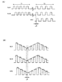
次に本実施形態の光学式検出装置を用いて対象物の位置を検出する手法の一例について説明する。図12(A)は、光源部LS1、LS2の発光制御についての信号波形例である。信号SLS1は、光源部LS1の発光制御信号であり、信号SLS2は、光源部LS2の発光制御信号であり、これらの信号SLS1、SLS2は逆相の信号になっている。また信号SRCは受光信号である。
7). Position Detection Method Next, an example of a method for detecting the position of an object using the optical detection device of the present embodiment will be described. FIG. 12A is an example of a signal waveform for light emission control of the light source units LS1 and LS2. The signal SLS1 is a light emission control signal of the light source unit LS1, the signal SLS2 is a light emission control signal of the light source unit LS2, and these signals SLS1 and SLS2 are in reverse phase. The signal SRC is a light reception signal.
例えば光源部LS1は、信号SLS1がHレベルの場合に点灯(発光)し、Lレベルの場合に消灯する。また光源部LS2は、信号SLS2がHレベルの場合に点灯(発光)し、Lレベルの場合に消灯する。従って図12(A)の第1の期間T1では、光源部LS1と光源部LS2が交互に点灯するようになる。即ち光源部LS1が点灯している期間では、光源部LS2は消灯する。これにより図9(A)に示すような照射光強度分布LID1が形成される。一方、光源部LS2が点灯している期間では、光源部LS1は消灯する。これにより図9(B)に示すような照射光強度分布LID2が形成される。 For example, the light source unit LS1 is turned on (emits light) when the signal SLS1 is at the H level, and is turned off when the signal SLS1 is at the L level. The light source unit LS2 is turned on (emits light) when the signal SLS2 is at the H level, and is turned off when the signal SLS2 is at the L level. Accordingly, in the first period T1 in FIG. 12A, the light source unit LS1 and the light source unit LS2 are alternately turned on. That is, the light source unit LS2 is turned off during the period when the light source unit LS1 is turned on. As a result, an irradiation light intensity distribution LID1 as shown in FIG. 9A is formed. On the other hand, the light source unit LS1 is turned off during the period when the light source unit LS2 is turned on. As a result, an irradiation light intensity distribution LID2 as shown in FIG. 9B is formed.
このように図8の制御部60は、第1の期間T1において、光源部LS1と光源部LS2を交互に発光(点灯)させる制御を行う。そしてこの第1の期間T1において、光学式検出装置(照射部)から見た対象物の位置する方向が検出される。具体的には、例えば上述した式(6)、(7)のようにGa/Gb=1になると共に制御量IaとIbの和が一定になるような発光制御を、第1の期間T1において行う。そして図10(B)に示すように対象物OBの位置する方向DDBを求める。例えば上式(10)、(11)から減衰係数の比fa/fbを求め、図10(A)、図10(B)で説明した手法により対象物OBの位置する方向DDBを求める
そして第1の期間T1に続く第2の期間T2では、受光部RUでの受光結果に基づいて対象物OBまでの距離(方向DDBに沿った方向での距離)を検出する。そして、検出された距離と、対象物OBの方向DDBとに基づいて、対象物の位置を検出する。即ち図10(B)において、光学式検出装置の配置位置PEから対象物OBまでの距離と、対象物OBの位置する方向DDBを求めれば、図8のXY平面での対象物OBのX、Y座標位置を特定できる。このように、光源の点灯タイミングと受光タイミングの時間のずれから距離を求め、これと角度結果を併せることで、対象物OBの位置を特定できる。
As described above, the
具体的には図12(A)では、発光制御信号SLS1、SLS2による光源部LS1、LS2の発光タイミングから、受光信号SRCがアクティブになるタイミング(反射光を受光したタイミング)までの時間Δtを検出する。即ち、光源部LS1、LS2からの光が対象物OBに反射されて受光部RUで受光されるまでの時間Δtを検出する。この時間Δtを検出することで、光の速度は既知であるため、対象物OBまでの距離を検出できる。即ち、光の到達時間のずれ幅(時間)を測定し、光の速度から距離を求める。 Specifically, in FIG. 12A, a time Δt from the light emission timing of the light source units LS1 and LS2 by the light emission control signals SLS1 and SLS2 to the timing when the light reception signal SRC becomes active (the timing when the reflected light is received) is detected. To do. That is, the time Δt from when the light from the light source units LS1 and LS2 is reflected by the object OB and received by the light receiving unit RU is detected. By detecting this time Δt, since the speed of light is known, the distance to the object OB can be detected. That is, the shift width (time) of the arrival time of light is measured, and the distance is obtained from the speed of light.
なお、光の速度はかなり速いため、電気信号だけでは単純な差分を求めて時間Δtを検出することが難しいという問題もある。このような問題を解決するためには、図12(B)に示すように発光制御信号の変調を行うことが望ましい。ここで図12(B)は、制御信号SLS1、SLS2の振幅により光の強度(電流量)を模式的に表している模式的な信号波形例である。 In addition, since the speed of light is quite high, there is also a problem that it is difficult to detect the time Δt by obtaining a simple difference using only an electric signal. In order to solve such a problem, it is desirable to modulate the light emission control signal as shown in FIG. Here, FIG. 12B is a schematic signal waveform example schematically representing light intensity (current amount) by the amplitude of the control signals SLS1 and SLS2.
具体的には図12(B)では、例えば公知の連続波変調のTOF(Time Of Flight)方式で距離を検出する。この連続波変調TOF方式では、一定周期の連続波で強度変調した連続光を用いる。そして、強度変調された光を照射すると共に、反射光を、変調周期よりも短い時間間隔で複数回受光することで、反射光の波形を復調し、照射光と反射光との位相差を求めることで、距離を検出する。なお図12(B)において制御信号SLS1、SLS2のいずれか一方に対応する光のみを強度変調してもよい。また図12(B)のようなクロック波形ではなく、連続的な三角波やSin波で変調した波形であってもよい。また、連続変調した光としてパルス光を用いるパルス変調のTOF方式で、距離を検出してもよい。距離検出手法の詳細については例えば特開2009−8537号などに開示されている。 Specifically, in FIG. 12B, the distance is detected by a known continuous wave modulation TOF (Time Of Flight) method, for example. In this continuous wave modulation TOF method, continuous light that is intensity-modulated with a continuous wave having a constant period is used. Then, while irradiating the intensity-modulated light and receiving the reflected light a plurality of times at time intervals shorter than the modulation period, the waveform of the reflected light is demodulated and the phase difference between the irradiated light and the reflected light is obtained. Thus, the distance is detected. In FIG. 12B, the intensity of only the light corresponding to one of the control signals SLS1 and SLS2 may be modulated. Further, instead of the clock waveform as shown in FIG. 12B, a waveform modulated by a continuous triangular wave or Sin wave may be used. Further, the distance may be detected by a pulse modulation TOF method using pulsed light as continuously modulated light. Details of the distance detection method are disclosed in, for example, Japanese Patent Application Laid-Open No. 2009-8537.
図13に光学式検出装置の変形例を示す。図13では第1、第2の照射部EU1、EU2が設けられる。これらの第1、第2の照射部EU1、EU2は、対象物OBの検出領域RDETの面に沿った方向において所与の距離DSだけ離れて配置される。即ち図8のX軸方向に沿って距離DSだけ離れて配置される。 FIG. 13 shows a modification of the optical detection device. In FIG. 13, first and second irradiation units EU1 and EU2 are provided. These first and second irradiation parts EU1, EU2 are arranged apart by a given distance DS in the direction along the surface of the detection area RDET of the object OB. That is, they are arranged apart by a distance DS along the X-axis direction in FIG.
第1の照射部EU1は、照射方向に応じて強度が異なる第1の照射光を放射状に出射する。第2の照射部EU2は、照射方向に応じて強度が異なる第2の照射光を放射状に出射する。受光部RUは、第1の照射部EU1からの第1の照射光が対象物OBに反射されることによる第1の反射光と、第2の照射部EU2からの第2の照射光が対象物OBに反射されることによる第2の反射光を受光する。そして検出部50は、受光部RUでの受光結果に基づいて、対象物OBの位置POBを検出する。
The first irradiation unit EU1 emits first irradiation light having different intensities according to the irradiation direction in a radial pattern. The second irradiation unit EU2 emits second irradiation light having different intensities according to the irradiation direction in a radial manner. The light receiving unit RU targets the first reflected light from the first irradiation light from the first irradiation unit EU1 reflected by the object OB and the second irradiation light from the second irradiation unit EU2. Second reflected light is received by being reflected by the object OB. And the
具体的には検出部50は、第1の反射光の受光結果に基づいて、第1の照射部EU1に対する対象物OBの方向を第1の方向DDB1(角度θ1)として検出する。また第2の反射光の受光結果に基づいて、第2の照射部EU2に対する対象物OBの方向を第2の方向DDB2(角度θ2)として検出する。そして検出された第1の方向DDB1(θ1)及び第2の方向DDB2(θ2)と、第1、第2の照射部EU1、EU2の間の距離DSとに基づいて、対象物OBの位置POBを求める。
Specifically, the
図13の変形例によれば、図12(A)、図12(B)のように光学式検出装置と対象物OBとの距離を求めなくても、対象物OBの位置POBを検出できるようになる。 According to the modification of FIG. 13, the position POB of the object OB can be detected without obtaining the distance between the optical detection device and the object OB as shown in FIGS. 12A and 12B. become.
8.照射方向の規制
さて、検出領域を設定して、ユーザーの指等の対象物を検出する場合に、照射部EUからの照射光が、図8のZ方向において広がった光になってしまうと、誤った検出が行われてしまうおそれがある。即ち、検出対象がユーザーの指であるのに、ユーザーの体の方を検出してしまうおそれがある。例えば図8において、ユーザーの体がスクリーン20の方に近づいただけで、検出領域RDETに、検出対象であるユーザーの指が存在すると誤検出されてしまうおそれがある。
8). Regulation of Irradiation Direction Now, when the detection area is set and an object such as a user's finger is detected, if the irradiation light from the irradiation unit EU becomes light spread in the Z direction in FIG. There is a risk of erroneous detection. That is, the user's body may be detected even though the detection target is the user's finger. For example, in FIG. 8, if the user's body is only close to the
そこで本実施形態の光学式検出装置では、照射光の照射方向を、対象物の検出領域RDETの面(XY平面に平行な面)に沿った方向(投射面に平行な方向)に規制する照射方向規制部(照射方向制限部)を設けている。具体的には図14(A)では、この照射方向規制部はスリットSLにより実現されている。このスリットSLは、検出領域RDETの面に沿った第1のスリット面SFL1と第2のスリット面SFL2を有する。このように本実施形態では、光学式検出装置の筐体HSに対して、照射方向に開口するスリットSLを設けることで、光学式検出装置の照射方向規制部を実現している。 Therefore, in the optical detection device of the present embodiment, the irradiation direction of the irradiation light is regulated to a direction (a direction parallel to the projection surface) along the surface of the object detection region RDET (a surface parallel to the XY plane). A direction regulating unit (irradiation direction limiting unit) is provided. Specifically, in FIG. 14A, this irradiation direction restricting portion is realized by a slit SL. The slit SL has a first slit surface SFL1 and a second slit surface SFL2 along the surface of the detection region RDET. As described above, in this embodiment, the slits SL that open in the irradiation direction are provided in the housing HS of the optical detection device, thereby realizing the irradiation direction restricting unit of the optical detection device.
このようなスリットSLを設ければ、ライトガイドLGからの光は、スリット面SFL1、SFL2に沿った方向に規制される。これにより、図8の照射部EUから出射される照射光が、X、Y平面に平行な光になるように規制できる。従って、検出領域への照射光が、Z方向に広がってしまう事態を防止でき、ユーザーの体がスクリーン20に近づいた場合に、ユーザーの体を指やタッチペンなどの対象物であると誤検出してしまう事態を防止できる。従って、Z方向の位置を検出する装置を設けなくても、対象物の適正な位置検出を実現できるようになる。
If such a slit SL is provided, light from the light guide LG is restricted in a direction along the slit surfaces SFL1 and SFL2. Thereby, it can regulate so that the irradiation light radiate | emitted from the irradiation part EU of FIG. 8 may turn into light parallel to a X, Y plane. Therefore, it is possible to prevent a situation in which the irradiation light to the detection area spreads in the Z direction, and when the user's body approaches the
また図14(B)では、スリット面SFL1、SFL2に対して凹部が形成されている。即ち図14(A)ではスリット面SFL1、SFL2は平らな形状になっているが、図14(B)では、スリット面SFL1、SFL2は平らな形状になっておらず、くぼみが形成されている。このような凹部を設けることでスリット面SFL1、SFL2での表面反射を抑制することが可能になり、XY平面に対して、より平行な光の照射光を検出領域RDETに対して出射できるようになる。 In FIG. 14B, recesses are formed in the slit surfaces SFL1, SFL2. That is, in FIG. 14A, the slit surfaces SFL1 and SFL2 are flat, but in FIG. 14B, the slit surfaces SFL1 and SFL2 are not flat and a depression is formed. . By providing such a concave portion, it becomes possible to suppress surface reflection at the slit surfaces SFL1 and SFL2, and it is possible to emit irradiation light of light parallel to the XY plane to the detection region RDET. Become.
なおスリット面SFL1、SFL2の表面に対して例えば無反射塗装などの加工を施すことで、凹部と同様の機能を実現することも可能である。また図14(A)、図14(B)では、照射光のZ方向でのブレを規制する照射方向規制部をスリットSLにより実現する場合について示しているが、例えばルーバーフィルムなどの光学シートを用いて、照射方向規制部を実現してもよい。例えば図9(A)のルーバーフィルムLFは、ライトガイドLGからの出射光の光指向の方向を法線方向に規制する機能を有する。従って、スリットSLによる照射方向規制部の機能と同様の機能を実現するためには、ライトガイドLGからの光の出射方向を、図8のXY平面に平行な方向に規制する配置構成のルーバーフィルムを設ければよい。 In addition, it is also possible to implement | achieve the function similar to a recessed part by giving the process of non-reflective coating etc. with respect to the surface of slit surface SFL1, SFL2. 14A and 14B show the case where the irradiation direction restricting portion that restricts the blur of the irradiation light in the Z direction is realized by the slit SL. For example, an optical sheet such as a louver film is used. The irradiation direction restricting unit may be realized by using. For example, the louver film LF shown in FIG. 9A has a function of restricting the direction of the light emitted from the light guide LG to the normal direction. Therefore, in order to realize the same function as the function of the irradiation direction restricting portion by the slit SL, the louver film having an arrangement configuration that restricts the light emitting direction from the light guide LG in a direction parallel to the XY plane of FIG. May be provided.
なお、以上では、曲線形状のライトガイドを有する光学式検出装置の構成について説明したが、本実施形態の光学式検出装置はこのような構成に限定されるものではなく種々の変形実施が可能である。例えば直線形状のライトガイドを用いた光学式検出装置であってもよい。 The configuration of the optical detection device having the curved light guide has been described above, but the optical detection device of the present embodiment is not limited to such a configuration, and various modifications can be made. is there. For example, an optical detection device using a linear light guide may be used.
9.取り付け装置の詳細な構造例
次に本実施形態の取り付け装置の詳細な構造例について図15、図16を用いて説明する。
9. Detailed Structural Example of Mounting Device Next, a detailed structural example of the mounting device of this embodiment will be described with reference to FIGS. 15 and 16.
図15は、本実施形態の取り付け装置を側面方向(X方向側)から見た側面図である。天井に取り付け装置を取り付けるための取り付け部31は、取り付け部32の取り付け用金具(ネジ、ネジ受け等)100により、取り付け部32に連結されて固定される。画像投射装置10は、取り付け部32の取り付け用金具102、104により、取り付け装置に連結されて固定される。
FIG. 15 is a side view of the attachment device of the present embodiment as viewed from the side surface direction (X direction side). The
図15では、取り付け部32と取り付け部33は、ベース金具により一体に形成されている。そして光学式検出装置40(照射部EU)は、取り付け部33の取り付け用金具106により、取り付け装置に連結されて固定される。なお光学式検出装置40の受光部RUは、例えば画像投射装置10と照射部EUとの間に設けられている。
In FIG. 15, the
図16(A)は、本実施形態の取り付け装置を正面方向(投射面側)から見た正面図である。図16(A)に示すように、取り付け装置は、取り付け部31により天井400に連結されて固定される。また光学式検出装置40は、画像投射装置10と投射面22(投射面が設けられる壁)との間に配置されるように、取り付け部33により取り付け装置に固定されている。
FIG. 16A is a front view of the attachment device of the present embodiment as viewed from the front direction (projection surface side). As shown in FIG. 16A, the attachment device is connected and fixed to the
なお図15では、取り付け部32と取り付け部33がベース金具により一体に形成される場合の例を示したが、本実施形態はこれに限定されない。例えば図16(B)に示すように、取り付け部32の金具と取り付け部33の金具を連結するための連結部34(ジョイント)を設けてもよい。この連結部34は、ネジ、ネジ受け、連結用ベース金具等の取り付け用金具112、114により構成される。
In addition, in FIG. 15, although the example in case the
図16(B)の構成によれば、取り付け部32と取り付け部33を、連結部34を用いて着脱自在にできる。従って、例えば光学式検出装置40を必要としないユーザーに対しては、取り付け部33を取り外すことで、取り付け装置を、画像投射装置10の通常の天吊り金具として提供できるようになる。一方、光学式検出装置40を必要とするユーザーに対しては、連結部34を用いて取り付け部33を連結することで、取り付け装置を、光学式検出装置付きの天吊り金具として提供できるようになる。
According to the configuration of FIG. 16B, the
10.キャリブレーション
さて、光学式検出装置40においては、対象物の適正な位置検出を実現するために、位置検出のためのキャリブレーションを行うことが望ましい。このために図17では、光学式検出装置40に対して、画像投射装置10等との間のインターフェース処理を行うI/F(インターフェース)部42を設けている。そして光学式検出装置40は、このI/F部42を介してキャリブレーション用情報を画像投射装置10に送信する。或いは、通常検出期間では、検出された位置情報をI/F部42を介して画像投射装置10に送信する。
10. Calibration Now, in the
図17に示すように、画像投射装置10は、I/F部16、通信部18を含む。そして画像投射装置10は、I/F部16を介してキャリブレーション用情報を光学式検出装置40から受信する。また通常の位置検出期間では、検出位置情報をI/F部16を介して光学式検出装置40から受信する。そして画像投射装置10は、受信したキャリブレーション用情報や通常検出期間での検出位置情報を、通信部18を介して、情報処理装置であるPC(パーソナルコンピュータ)に送信する。この通信部18は、有線の通信を行うものであってもよいし、無線LAN等の無線の通信を行うものであってもよい。なお、キャリブレーション用情報は、例えばキャリブレーション用のプログラムや、キャリブレーション期間での検出位置情報などである。
As shown in FIG. 17, the
I/F部42は、例えばUSB(Universal Serial Busなどにより実現できる。この場合には図17に示すように、光学式検出装置40のI/F部42(USBインターフェース)は、USBケーブルを介して画像投射装置10のI/F部16に接続される。このようなUSBを用いれば、画像投射装置10が元々有しているUSBの端子を用いて、光学式検出装置40を接続できるようになるため、汎用性を向上できる。
The I /
またUSBを用いれば、光学式検出装置40は、I/F部42を介して画像投射装置10から電源を受電することが可能になる。具体的には光学式検出装置40は、USBのVBUSを介して画像投射装置10から電源を受電する。そして光学式検出装置40は、受電した電源に基づいて動作する。例えば受電した電源を用いて発光素子を発光させたり、検出部50、制御部60等のIC(集積回路装置)を動作させる。
If the USB is used, the
なお、光学式検出装置40のI/F部42は、USBインターフェースには限定されず、USB以外の有線の高速シリアルインターフェースを用いてもよい。この場合には、電源の給電や受電が可能な高速シリアルインターフェースであることが望ましい。或いは、有線のインターフェースではなく、ブルートゥースや無線LANなどの無線インターフェースであってもよい。また光学式検出装置40と図17のPC(広義には情報処理装置)が、無線インターフェースで通信するようにしてもよい。この場合には、キャリブレーション用情報や通常検出期間での検出位置情報は、無線インターフェースを介してPCに送信される。
The I /
本実施形態では、図8の検出部50が、画像投射装置10が投射面22に対して、後述する図19(C)に示すようなキャリブレーション用画面の画像を投射した後に、検出領域での対象物の位置情報を検出する。そして光学式検出装置40は、検出された対象物の位置情報(広義にはキャリブレーション用情報)を、画像投射装置10に送信する。具体的には、検出された位置情報をI/F部42を介して画像投射装置10に送信する。
In the present embodiment, the
すると画像投射装置10は、受信した位置情報を、通信部18を介して、画像投射装置10を制御するPCに送信する。これにより、PC(PC上で動作するプログラム)は、キャリブレーション用画面においてユーザーが正しい位置を指示したか否かなどを判断できるようになる。
Then, the
また光学式検出装置40は、キャリブレーション処理を行うためのキャリブレーション用プログラムを、その記憶部(EEPROM等の不揮発性メモリー)に記憶している。そして光学式検出装置40は、このキャリブレーション用プログラムを、I/F部42を介して画像投射装置10に送信する。
The
すると画像投射装置10は、受信したキャリブレーション用プログラムを、通信部18を介してPCに送信する。これにより、PCは、受信したキャリブレーション用プログラムをインストールして、キャリブレーション用プログラムによるキャリブレーション処理を実行できるようになる。なお、検出された位置情報やキャリブレーション用プログラムなどを、無線のI/F部42を介して直接にPCに送信するようにしてもよい。
Then, the
次に本実施形態のキャリブレーション処理の具体例について図18のフローチャートを用いて説明する。 Next, a specific example of the calibration processing of the present embodiment will be described with reference to the flowchart of FIG.
ユーザーは、画像投射装置10の設置時に、本実施形態の取り付け装置に対して、取り付け部32を用いて画像投射装置10を取り付ける。また取り付け装置に対して、取り付け部33を用いて光学式検出装置40を取り付ける。そして、例えばUSBケーブルにより、画像投射装置10と光学式検出装置40を接続する。すると、画像投射装置10が光学式検出装置40に対してUSBを介して電源を供給し(ステップS1)、これにより光学式検出装置40の動作が開始する。
The user attaches the
次に、光学式検出装置40が画像投射装置10に対してUSBを介してキャリブレーション用プログラムを送信する(ステップS2)。すると、画像投射装置10がPCに対して、無線LANや有線通信でキャリブレーション用プログラムを送信する(ステップS3)。
Next, the
次に図19(A)に示すように、PCにおいてキャリブレーション用プログラムのインストールが実行される(ステップS4)。そしてインストールが終了すると、PCの表示部に対して、図19(B)に示すようなキャリブレーション開始選択画面が表示される(ステップS5)。 Next, as shown in FIG. 19A, the installation of the calibration program is executed on the PC (step S4). When the installation is completed, a calibration start selection screen as shown in FIG. 19B is displayed on the display unit of the PC (step S5).
図19(B)のキャリブレーション開始選択画面において、ユーザーがキャリブレーションの開始を選択すると(ステップS6)、PCからの指示により画像投射装置10が、図19(C)に示すようなキャリブレーション用画面の画像を、スクリーン20(投射面)に投射する(ステップS7)。図19(C)のキャリブレーション用画面には、ユーザーが指示(ポインティング)すべき複数のポイントが表示されている。そして、ユーザーが指示すべきポイントをユーザーに知らせるためのカーソルも表示されている。従って、図1に示すようにユーザーは、カーソルのあるポイントを指等を用いて指示する。すると、このキャリブレーション用画面においてユーザーが指等により指示した位置を、光学式検出装置40が検出する(ステップS8)。即ちユーザーの指の位置のX、Y座標を検出する。
When the user selects the start of calibration on the calibration start selection screen shown in FIG. 19B (step S6), the
そして光学式検出装置40が画像投射装置10に対して、USBを介して、検出位置情報を送信する(ステップS9)。すると画像投射装置10がPCに対して、無線LANや有線通信により検出位置情報を送信する(ステップS10)。
Then, the
次にPCが、ユーザーにより指示された位置を判断して、キャリブレーション処理を実行する(ステップS11)。例えば図19(C)の各ポイントの位置と、ユーザーが実際に指示した位置を比較して、検出位置のズレを調整するためのキャリブレーション処理を実行する。そして、キャリブレーションが完了したか否かを判断し(ステップS12)、全てのキャリブレーションが完了するまでステップS8〜S11の処理を繰り返す。 Next, the PC determines the position instructed by the user and executes calibration processing (step S11). For example, the position of each point in FIG. 19C is compared with the position actually instructed by the user, and a calibration process for adjusting the deviation of the detected position is executed. Then, it is determined whether or not calibration is completed (step S12), and the processes of steps S8 to S11 are repeated until all calibrations are completed.
以上のように説明したキャリブレーション処理により求められたキャリブレーションの調整情報(検出位置のズレを調整する情報)は、例えばPCに保存される。そして、光学式検出装置40が通常の位置検出を行う通常動作時においては、このキャリブレーション調整情報に基づいて、検出位置のズレの補正処理が行われる。なお、キャリブレーション調整情報を、PCから画像投射装置10を介して光学式検出装置40に送信して、光学式検出装置40側において検出位置のズレの補正処理を行うようにしてもよい。
The calibration adjustment information (information for adjusting the displacement of the detection position) obtained by the calibration process described above is stored in a PC, for example. Then, during the normal operation in which the
以上のようにすれば、画像投射装置10の設置時にキャリブレーション処理を実行して、キャリブレーション調整情報を得ることが可能になる。そして画像投射装置10の設置後の通常動作時においては、得られたキャリブレーション調整情報を用いて、検出位置のズレの補正処理を実行して、正確な位置検出を実現できるようになる。
If it carries out as mentioned above, it will become possible to perform a calibration process at the time of installation of
なお、以上のように本実施形態について詳細に説明したが、本発明の新規事項および効果から実体的に逸脱しない多くの変形が可能であることは当業者には容易に理解できるであろう。従って、このような変形例はすべて本発明の範囲に含まれるものとする。例えば、明細書又は図面において、少なくとも一度、より広義または同義な異なる用語と共に記載された用語は、明細書又は図面のいかなる箇所においても、その異なる用語に置き換えることができる。また取り付け装置、光学式検出装置、投写型表示装置等の構成、動作も本実施形態で説明したものに限定されず、種々の変形実施が可能である。 Although the present embodiment has been described in detail as described above, it will be easily understood by those skilled in the art that many modifications can be made without departing from the novel matters and effects of the present invention. Accordingly, all such modifications are intended to be included in the scope of the present invention. For example, a term described at least once together with a different term having a broader meaning or the same meaning in the specification or the drawings can be replaced with the different term in any part of the specification or the drawings. Further, the configuration and operation of the attachment device, the optical detection device, the projection display device, and the like are not limited to those described in this embodiment, and various modifications can be made.
EU 照射部、RU 受光部、ARD 表示エリア、RDET 検出領域、
LG、LG1、LG2 ライトガイド、LS1、LS2、LS11〜LS22 光源部、
RS、RS1、RS2 反射シート、PS、PS1、PS2 プリズムシート、
LF、LF1、LF2 ルーバーフィルム、LE、LE1、LE2 照射方向設定部、
LT 照射光、LID1 第1の照射光強度分布、LID2 第2の照射光強度分布、
SLB 入射光用スリット、SLB1 第1のスリット面、
SLB2 第2のスリット面、SL 照射光用スリット、
SFL1 第1のスリット面、SFL2 第2のスリット面、
10 画像投射装置、12 投射部、14 放熱部、16 I/F部、18 通信部、
20 スクリーン、22 投射面、31 第1の取り付け部、32 第2の取り付け部、
33 第3の取り付け部、34 連結部、40 光学式検出装置、42 I/F部、
50 検出部、60 制御部、
100、102、104、106、112、114 取り付け用金具、400 天井
EU irradiation unit, RU light receiving unit, ARD display area, RDET detection region,
LG, LG1, LG2 Light guide, LS1, LS2, LS11 to LS22 Light source unit,
RS, RS1, RS2 reflective sheet, PS, PS1, PS2 prism sheet,
LF, LF1, LF2 louver film, LE, LE1, LE2 irradiation direction setting section,
LT irradiation light, LID1 first irradiation light intensity distribution, LID2 second irradiation light intensity distribution,
SLB incident light slit, SLB1 first slit surface,
SLB2 second slit surface, slit for SL irradiation light,
SFL1 first slit surface, SFL2 second slit surface,
10 image projection device, 12 projection unit, 14 heat dissipation unit, 16 I / F unit, 18 communication unit,
20 screens, 22 projection surfaces, 31 first attachment part, 32 second attachment part,
33 3rd attachment part, 34 connection part, 40 optical detection apparatus, 42 I / F part,
50 detection unit, 60 control unit,
100, 102, 104, 106, 112, 114 Mounting bracket, 400 Ceiling
Claims (16)
取り付け対象に対して取り付け装置を取り付けるための第1の取り付け部と、
投射面に画像を投射する前記画像投射装置を取り付けるための第2の取り付け部と、
前記投射面に沿って設定された検出領域において対象物を検出する光学式検出装置を取り付けるための第3の取り付け部と、
を有することを特徴とする取り付け装置。 A mounting device for an image projection device,
A first attachment portion for attaching the attachment device to the attachment object;
A second mounting portion for mounting the image projection device that projects an image on a projection surface;
A third attachment portion for attaching an optical detection device for detecting an object in a detection region set along the projection surface;
A mounting device comprising:
前記画像投射装置は、熱を外部に放熱するための放熱部を有し、
前記光学式検出装置は、前記第3の取り付け部により、前記放熱部を避けた領域に取り付けられることを特徴とする取り付け装置。 In claim 1,
The image projection device has a heat radiating portion for radiating heat to the outside,
The optical detection device is attached to a region avoiding the heat radiating portion by the third attachment portion.
前記検出領域の面に交差する入射方向の光が前記光学式検出装置に入射されるのを規制する入射光規制部を有することを特徴とする取り付け装置。 In claim 1 or 2,
An attachment device comprising an incident light restricting portion for restricting light in an incident direction intersecting a surface of the detection region from being incident on the optical detection device.
前記入射光規制部は、
前記画像投射装置からの投射光が前記投射面で反射されることによる反射光又は前記光学式検出装置からの照射光が前記投射面又は前記画像投射装置で反射されることによる反射光が、前記光学式検出装置に入射されるのを規制することを特徴とする取り付け装置。 In claim 3,
The incident light restricting portion is
Reflected light resulting from reflection of the projection light from the image projection device on the projection surface or reflected light from irradiation light from the optical detection device reflected on the projection surface or the image projection device, An attachment device for restricting incidence to an optical detection device.
前記入射光規制部は、
前記検出領域の面に沿った方向のスリット面を有する入射光用スリットであることを特徴とする取り付け装置。 In claim 3 or 4,
The incident light restricting portion is
An attachment device comprising an incident light slit having a slit surface in a direction along the surface of the detection region.
前記スリット面には反射防止層又は凹部が設けられていることを特徴とする取り付け装置。 In claim 5,
An attachment device, wherein the slit surface is provided with an antireflection layer or a recess.
前記入射光用スリットは、前記スリット面として、前記光学式検出装置を挟むように設けられる第1のスリット面及び第2のスリット面を有することを特徴とする取り付け装置。 In claim 5 or 6,
The incident light slit has a first slit surface and a second slit surface provided so as to sandwich the optical detection device as the slit surface.
前記光学式検出装置は、前記光学式検出装置から出射される前記対象物の検出用の照射光を、前記検出領域の面に沿った方向に規制する照射光用スリットを有し、
前記第3の取り付け部から前記入射光用スリットの端部までの高さをHS1とし、前記第3の取り付け部から前記照射光用スリットの端部までの高さをHS2とした場合に、HS1>HS2であることを特徴とする取り付け装置。 In any one of Claims 1 thru | or 7,
The optical detection device has an irradiation light slit for restricting irradiation light for detection of the object emitted from the optical detection device in a direction along the surface of the detection region,
When the height from the third attachment portion to the end of the incident light slit is HS1, and the height from the third attachment portion to the irradiation light slit is HS2, HS1 > HS2 is a mounting device.
前記第3の取り付け部により取り付けられる前記光学式検出装置を更に有し、
前記光学式検出装置は、
前記検出領域に対して前記対象物の検出用の照射光を出射する照射部と、
前記照射光が前記対象物に反射されることによる反射光を受光する受光部と、
前記受光部での受光結果に基づいて、前記対象物の位置情報を検出する検出部とを含むことを特徴とする取り付け装置。 In any one of Claims 1 thru | or 8.
The optical detection device attached by the third attachment portion;
The optical detection device is:
An irradiation unit that emits irradiation light for detecting the object with respect to the detection region;
A light receiving unit for receiving reflected light by the irradiation light being reflected by the object;
And a detection unit that detects position information of the object based on a light reception result of the light reception unit.
前記照射部は、
前記検出領域の各位置に応じて強度が異なる照射光を出射することを特徴とする取り付け装置。 In claim 9,
The irradiation unit is
An attachment device that emits irradiation light having different intensities according to each position of the detection region.
前記照射部は、
光源光を出射する光源部と、
前記光源部からの前記光源光を曲線状の導光経路に沿って導光する曲線形状のライトガイドと、
前記ライトガイドの外周側から出射される前記光源光を受け、曲線形状の前記ライトガイドの内周側から外周側へと向かう方向に前記照射光の照射方向を設定する照射方向設定部を含むことを特徴とする取り付け装置。 In claim 9 or 10,
The irradiation unit is
A light source unit for emitting light source light;
A curved light guide for guiding the light source light from the light source section along a curved light guide path;
An irradiation direction setting unit that receives the light source light emitted from the outer peripheral side of the light guide and sets the irradiation direction of the irradiation light in a direction from the inner peripheral side to the outer peripheral side of the curved light guide; A mounting device characterized by.
前記光学式検出装置は、前記照射部として第1の照射部及び第2の照射部を有し、
前記第1の照射部は、
照射方向に応じて強度が異なる第1の照射光を放射状に出射し、
前記第2の照射部は、
照射方向に応じて強度が異なる第2の照射光を放射状に出射し、
前記受光部は、
前記第1の照射部からの前記第1の照射光が前記対象物に反射されることによる第1の反射光と、前記第2の照射部からの前記第2の照射光が前記対象物に反射されることによる第2の反射光を受光し、
前記検出部は、
前記受光部での受光結果に基づいて、前記対象物の位置を検出することを特徴とする取り付け装置。 In claim 9 or 10,
The optical detection device has a first irradiation unit and a second irradiation unit as the irradiation unit,
The first irradiation unit includes:
The first irradiation light having different intensities according to the irradiation direction is emitted radially,
The second irradiation unit includes:
The second irradiation light having different intensities according to the irradiation direction is emitted radially,
The light receiving unit is
The first reflected light by the first irradiation light from the first irradiation part being reflected by the object and the second irradiation light from the second irradiation part to the object. Receiving the second reflected light by being reflected,
The detector is
An attachment device that detects a position of the object based on a light reception result in the light receiving unit.
前記検出部は、
前記画像投射装置が前記投射面に対してキャリブレーション用画面の画像を投射した後に、前記検出領域での前記対象物の位置情報を検出し、
前記光学式検出装置は、
検出された前記対象物の位置情報を、前記画像投射装置又は前記画像投射装置を制御する情報処理装置に対して送信することを特徴とする取り付け装置。 In any one of Claims 1 to 12,
The detector is
After the image projection device projects an image of a calibration screen on the projection surface, the position information of the object in the detection region is detected,
The optical detection device is:
The mounting apparatus, wherein the detected position information of the object is transmitted to the image projection apparatus or an information processing apparatus that controls the image projection apparatus.
前記光学式検出装置は、インターフェース部を含み、
前記光学式検出装置は、前記インターフェース部を介してキャリブレーション用情報を送信することを特徴とする取り付け装置。 In claim 13,
The optical detection device includes an interface unit,
The optical detection device transmits calibration information via the interface unit.
前記光学式検出装置は、前記インターフェース部を介して前記画像投射装置から電源を受電することを特徴とする取り付け装置。 In claim 14,
The optical detection device receives power from the image projection device via the interface unit.
前記取り付け装置に取り付けられた前記画像投射装置と、
を含むことを特徴とする投写型表示装置。 An attachment device according to any of claims 1 to 15,
The image projection device attached to the attachment device;
A projection type display device comprising:
Priority Applications (3)
| Application Number | Priority Date | Filing Date | Title |
|---|---|---|---|
| JP2010120205A JP2011248041A (en) | 2010-05-26 | 2010-05-26 | Mounting device and projection type display apparatus |
| US13/096,502 US9057477B2 (en) | 2010-05-26 | 2011-04-28 | Projection display system and attaching device |
| US14/708,615 US9625799B2 (en) | 2010-05-26 | 2015-05-11 | Attaching device of image projection device |
Applications Claiming Priority (1)
| Application Number | Priority Date | Filing Date | Title |
|---|---|---|---|
| JP2010120205A JP2011248041A (en) | 2010-05-26 | 2010-05-26 | Mounting device and projection type display apparatus |
Publications (2)
| Publication Number | Publication Date |
|---|---|
| JP2011248041A true JP2011248041A (en) | 2011-12-08 |
| JP2011248041A5 JP2011248041A5 (en) | 2013-08-08 |
Family
ID=45021698
Family Applications (1)
| Application Number | Title | Priority Date | Filing Date |
|---|---|---|---|
| JP2010120205A Withdrawn JP2011248041A (en) | 2010-05-26 | 2010-05-26 | Mounting device and projection type display apparatus |
Country Status (2)
| Country | Link |
|---|---|
| US (2) | US9057477B2 (en) |
| JP (1) | JP2011248041A (en) |
Cited By (4)
| Publication number | Priority date | Publication date | Assignee | Title |
|---|---|---|---|---|
| JP2015158558A (en) * | 2014-02-24 | 2015-09-03 | セイコーエプソン株式会社 | projector |
| JP2016122179A (en) * | 2014-12-25 | 2016-07-07 | パナソニックIpマネジメント株式会社 | Projection device and projection method |
| KR101638893B1 (en) * | 2015-02-09 | 2016-07-12 | 김영근 | Switch device for water saving apparatus |
| CN110456939A (en) * | 2019-07-10 | 2019-11-15 | 漳州万利达科技有限公司 | Infrared touch-control optical mode regulating jig and adjusting method |
Families Citing this family (16)
| Publication number | Priority date | Publication date | Assignee | Title |
|---|---|---|---|---|
| JP2011248041A (en) * | 2010-05-26 | 2011-12-08 | Seiko Epson Corp | Mounting device and projection type display apparatus |
| JP2012160041A (en) * | 2011-02-01 | 2012-08-23 | Seiko Epson Corp | Irradiation unit, optical detector and information processing system |
| JP5742398B2 (en) * | 2011-04-06 | 2015-07-01 | セイコーエプソン株式会社 | Optical position detection device and display system with input function |
| TW201327325A (en) * | 2011-12-23 | 2013-07-01 | Azurewave Technologies Inc | Optical touch control module |
| WO2013099407A1 (en) | 2011-12-28 | 2013-07-04 | 株式会社ニコン | Display device and projection device |
| WO2013104060A1 (en) | 2012-01-11 | 2013-07-18 | Smart Technologies Ulc | Interactive input system and method |
| JP6111706B2 (en) * | 2013-02-01 | 2017-04-12 | セイコーエプソン株式会社 | Position detection apparatus, adjustment method, and adjustment program |
| JP6075122B2 (en) * | 2013-03-05 | 2017-02-08 | 株式会社リコー | System, image projection apparatus, information processing apparatus, information processing method, and program |
| US10073518B2 (en) * | 2013-08-19 | 2018-09-11 | Qualcomm Incorporated | Automatic calibration of eye tracking for optical see-through head mounted display |
| CN105094456A (en) * | 2014-05-21 | 2015-11-25 | 中强光电股份有限公司 | Optical touch-control device and correction method thereof |
| GB2536604A (en) * | 2014-11-14 | 2016-09-28 | Promethean Ltd | Touch sensing systems |
| TWI567475B (en) * | 2014-12-02 | 2017-01-21 | 明基電通股份有限公司 | Projection fixing apparatus |
| US10197233B2 (en) * | 2014-12-26 | 2019-02-05 | Maxell, Ltd. | Illumination device |
| JP6962026B2 (en) * | 2017-06-22 | 2021-11-05 | オムロン株式会社 | Gesture input device |
| JP7119488B2 (en) * | 2018-03-27 | 2022-08-17 | セイコーエプソン株式会社 | Projector and projector control method |
| DE102019212673A1 (en) * | 2019-07-22 | 2021-01-28 | OSRAM CONTINENTAL GmbH | OPTICAL ARRANGEMENT AND PROCEDURE |
Family Cites Families (16)
| Publication number | Priority date | Publication date | Assignee | Title |
|---|---|---|---|---|
| JP3968477B2 (en) * | 1997-07-07 | 2007-08-29 | ソニー株式会社 | Information input device and information input method |
| JP3821194B2 (en) | 1998-03-31 | 2006-09-13 | セイコーエプソン株式会社 | Pointing position detecting device and method, presentation system, information storage medium |
| US6512507B1 (en) * | 1998-03-31 | 2003-01-28 | Seiko Epson Corporation | Pointing position detection device, presentation system, and method, and computer-readable medium |
| KR100382439B1 (en) * | 1998-05-25 | 2003-05-09 | 마쯔시다덴기산교 가부시키가이샤 | Range finder and camera |
| JP2001125741A (en) | 1999-10-29 | 2001-05-11 | Seiko Epson Corp | Pointing position detector, image display device, presentation system and information storage medium |
| JP2001142643A (en) | 1999-11-18 | 2001-05-25 | Ricoh Co Ltd | Device for inputting/detecting coordinates |
| US6379012B1 (en) * | 2000-06-20 | 2002-04-30 | Draper, Inc. | Overhead projector mount system |
| US7576727B2 (en) * | 2002-12-13 | 2009-08-18 | Matthew Bell | Interactive directed light/sound system |
| TWI277042B (en) * | 2003-10-28 | 2007-03-21 | Seiko Epson Corp | Electro-optical device, electronic equipment, and method of manufacturing electro-optical device |
| JP4429083B2 (en) * | 2004-06-03 | 2010-03-10 | キヤノン株式会社 | Shading type coordinate input device and coordinate input method thereof |
| JP2006003414A (en) | 2004-06-15 | 2006-01-05 | Ikuaki Cho | Exhibiting device |
| JP2006244192A (en) | 2005-03-04 | 2006-09-14 | Canon Inc | Optical coordinate input device |
| JP2006319950A (en) | 2005-04-13 | 2006-11-24 | Hitachi Ltd | Image display device |
| JP2009008537A (en) | 2007-06-28 | 2009-01-15 | Fujifilm Corp | Range image device and imaging device |
| JP2011248041A (en) * | 2010-05-26 | 2011-12-08 | Seiko Epson Corp | Mounting device and projection type display apparatus |
| WO2013104060A1 (en) * | 2012-01-11 | 2013-07-18 | Smart Technologies Ulc | Interactive input system and method |
-
2010
- 2010-05-26 JP JP2010120205A patent/JP2011248041A/en not_active Withdrawn
-
2011
- 2011-04-28 US US13/096,502 patent/US9057477B2/en not_active Expired - Fee Related
-
2015
- 2015-05-11 US US14/708,615 patent/US9625799B2/en active Active
Cited By (5)
| Publication number | Priority date | Publication date | Assignee | Title |
|---|---|---|---|---|
| JP2015158558A (en) * | 2014-02-24 | 2015-09-03 | セイコーエプソン株式会社 | projector |
| JP2016122179A (en) * | 2014-12-25 | 2016-07-07 | パナソニックIpマネジメント株式会社 | Projection device and projection method |
| KR101638893B1 (en) * | 2015-02-09 | 2016-07-12 | 김영근 | Switch device for water saving apparatus |
| CN110456939A (en) * | 2019-07-10 | 2019-11-15 | 漳州万利达科技有限公司 | Infrared touch-control optical mode regulating jig and adjusting method |
| CN110456939B (en) * | 2019-07-10 | 2022-08-12 | 漳州万利达科技有限公司 | Infrared touch control light mode adjusting jig and adjusting method |
Also Published As
| Publication number | Publication date |
|---|---|
| US20110291990A1 (en) | 2011-12-01 |
| US20150268542A1 (en) | 2015-09-24 |
| US9625799B2 (en) | 2017-04-18 |
| US9057477B2 (en) | 2015-06-16 |
Similar Documents
| Publication | Publication Date | Title |
|---|---|---|
| JP2011248041A (en) | Mounting device and projection type display apparatus | |
| JP5703644B2 (en) | Optical detection system, electronic equipment | |
| JP5445321B2 (en) | Optical detection device, display device, and electronic apparatus | |
| US8687205B2 (en) | Optical detection device, display device, and electronic apparatus | |
| JP5668416B2 (en) | Optical detection apparatus, electronic apparatus, and optical detection method | |
| US20100085329A1 (en) | Optical touch display device, optical touch sensing device and touch sensing method | |
| US20120212454A1 (en) | Optical position detecting device and display system provided with input function | |
| CN102812424A (en) | Lens arrangement for light-based touch screen | |
| JP2012150636A (en) | Projection type display device and information processing system | |
| WO2011074331A1 (en) | Coordinate sensor and display device | |
| US20150035804A1 (en) | Optical position detection device and display system with input function | |
| US9791978B2 (en) | Optical touch module for sensing touch object and touch detecting method thereof | |
| TWI493389B (en) | Control system, mouse and control method thereof | |
| US8854337B2 (en) | Optical position detection device, light receiving unit, and display system with input function | |
| JP5672018B2 (en) | Position detection system, display system, and information processing system | |
| JP5655450B2 (en) | Optical detection apparatus and information processing system | |
| JP5672031B2 (en) | Optical detection device, electronic device, and projection display device | |
| JP2012194913A (en) | Optical detection device, display system, and information processing system | |
| JP2012194128A (en) | Optical position detector and input function equipped-display system | |
| JP2012194127A (en) | Optical position detector and input function equipped-display system | |
| JP2013114420A (en) | Information processor, information processor control method and program | |
| JP2012160042A (en) | Irradiation unit, optical detector, display system and information processing system | |
| JP2012160044A (en) | Irradiation unit, optical detector, display system and information processing system | |
| JP2012194129A (en) | Optical position detector and input function equipped-display system |
Legal Events
| Date | Code | Title | Description |
|---|---|---|---|
| A621 | Written request for application examination |
Free format text: JAPANESE INTERMEDIATE CODE: A621 Effective date: 20130315 |
|
| A521 | Written amendment |
Free format text: JAPANESE INTERMEDIATE CODE: A523 Effective date: 20130626 |
|
| A977 | Report on retrieval |
Free format text: JAPANESE INTERMEDIATE CODE: A971007 Effective date: 20131128 |
|
| A131 | Notification of reasons for refusal |
Free format text: JAPANESE INTERMEDIATE CODE: A131 Effective date: 20131203 |
|
| A761 | Written withdrawal of application |
Free format text: JAPANESE INTERMEDIATE CODE: A761 Effective date: 20140116 |