JP2011237773A - Imaging apparatus and imaging method - Google Patents
Imaging apparatus and imaging method Download PDFInfo
- Publication number
- JP2011237773A JP2011237773A JP2011062025A JP2011062025A JP2011237773A JP 2011237773 A JP2011237773 A JP 2011237773A JP 2011062025 A JP2011062025 A JP 2011062025A JP 2011062025 A JP2011062025 A JP 2011062025A JP 2011237773 A JP2011237773 A JP 2011237773A
- Authority
- JP
- Japan
- Prior art keywords
- grating
- light
- intensity distribution
- detector
- phase image
- Prior art date
- Legal status (The legal status is an assumption and is not a legal conclusion. Google has not performed a legal analysis and makes no representation as to the accuracy of the status listed.)
- Withdrawn
Links
Images


Abstract
Description
本発明は、撮像装置および撮像方法に関し、特に、タルボ干渉を用いて被検体を撮像する撮像装置および撮像方法に関するものである。 The present invention relates to an imaging apparatus and an imaging method, and more particularly to an imaging apparatus and an imaging method for imaging a subject using Talbot interference.
可視光やX線を含む様々な波長の光の干渉を利用したイメージング技術が知られている。
そのようなイメージング方法の1つとしてタルボ干渉法が知られている。
タルボ干渉法の概要を説明する。光を被検体に照射すると、被検体を透過することによって光の位相が変化する。
この光を特定のパターンを有した第1の格子(回折格子)に照射すると、第1の格子で回折された光は一定の距離で干渉して自己像と呼ばれる干渉パターンを形成する。この自己像を解析すると、被検体の位相に関する情報を得ることができる。
Imaging techniques using interference of light of various wavelengths including visible light and X-rays are known.
Talbot interferometry is known as one of such imaging methods.
An outline of Talbot interferometry will be described. When the subject is irradiated with light, the phase of the light changes by passing through the subject.
When this light is irradiated onto a first grating (diffraction grating) having a specific pattern, the light diffracted by the first grating interferes at a certain distance to form an interference pattern called a self-image. By analyzing this self-image, information on the phase of the subject can be obtained.
また、特許文献1には自己像が形成される位置に光を遮蔽する遮蔽部と、光を透過する透過部を有する遮蔽格子を配置し、自己像の一部を遮蔽することによってモアレを形成させている。
記載されているような、自己像を用いてモアレを形成させ、このモアレを検出する方法を用いると、自己像の周期よりも大きな解像度の検出器を用いて被検体の位相に関する情報を得ることができる。
一般的に、光としてX線を用いると、自己像の周期が検出器の解像度よりも小さくなるため、特許文献1に記載されているようにモアレを形成される方法は光としてX線を用いる際に特に有効である。特許文献1に記載されている撮像装置は、自己像が形成される位置に光を遮蔽する遮蔽部と光を透過する透過部を有する第2の格子(遮蔽格子)を配置し、自己像の一部を遮蔽することによってモアレを形成させている。
Further, in
By using a method that forms moiré using a self-image as described and detects this moiré, information about the phase of the subject can be obtained using a detector with a resolution larger than the period of the self-image. Can do.
In general, when X-rays are used as light, the period of the self-image is smaller than the resolution of the detector. Therefore, the method for forming moire as described in
第2の格子を用いてモアレを生じさせる方法には、幾つか種類がある。
例えば自己像と周期も含めて同じ形状を持った第2の格子を用い、その角度を微妙に回転させることにより視認性の高いモアレを出す方法がある。
また、自己像と僅かに周期の異なる第2の格子を用いてモアレを出す手法もある。
いずれにせよ、自己像をモアレによって強調すると言う点では同じである。
また、このモアレの変位から被検体による光の波面形状の変化を計算する方法も幾つか存在する。
その一つがモアレの周期を波数空間を用いて解析する方法であり、具体的にはフーリエ変換やウェーブレット変換等が挙げられる。
但し、本明細書においてフーリエ変換は窓関数付フーリエ変換を含む。
非特許文献1には、フーリエ変換法を用いてモアレをフーリエ変換し、波数空間上のモアレ成分を抽出解析する方法が記載されている。この方法の原理を簡単に説明する。
まず、検出結果をフーリエ変換し空間周波数スペクトルを得る。次にモアレの基本周期成分の周波数(以後、キャリア周波数と呼ぶ)のスペクトル及びその周辺を切り出して原点に移動する。
この周波数スペクトルを逆フーリエ変換して被検体の微分位相像を求め、さらに積分することで被検体の位相像が得られる。
There are several methods for generating moire using the second grating.
For example, there is a method of using a second grating having the same shape including the self image and the period, and producing a moire with high visibility by slightly rotating the angle.
There is also a method of generating moire using a second grating having a slightly different period from the self-image.
In any case, it is the same in that the self-image is emphasized by moire.
There are also some methods for calculating the change in the wavefront shape of light by the subject from the displacement of the moire.
One of them is a method of analyzing the moiré period using a wave number space, and specifically includes Fourier transform, wavelet transform, and the like.
However, in this specification, the Fourier transform includes a Fourier transform with a window function.
Non-Patent
First, the detection result is Fourier transformed to obtain a spatial frequency spectrum. Next, the spectrum of the frequency of the fundamental period component of moire (hereinafter referred to as carrier frequency) and its periphery are cut out and moved to the origin.
The frequency spectrum is subjected to inverse Fourier transform to obtain a differential phase image of the subject, and further integrated to obtain a phase image of the subject.
非特許文献1で開示されている技術は1次元のフーリエ変換法であり、この変換法では、2次元方向の微分位相像を得ることはできない。
そこで、タルボ干渉計における第1の格子を2次元構造にすることにより、2次元のパターンを持つ自己像を形成する。そして、その自己像に対応した適切な形状の第2の格子を設置することにより2次元のモアレを出現させることができる。
しかし、モアレの周期を波数空間を用いて解析する場合には、どのような形状のモアレでも同様な精度で光の位相を回復できるわけではない。
すなわち、モアレの周期を波数空間を用いて解析する方法を用いた位相回復に際しては、第1の格子と第2の格子の組合せによっては、精度の点で必ずしも満足の行く結果が得られないことがある。
このため、第1の格子と第2の格子の組合せにより、波数空間を用いて解析する方法に適したモアレを形成することが重要な課題となる。
The technique disclosed in
Therefore, a self-image having a two-dimensional pattern is formed by making the first grating in the Talbot interferometer into a two-dimensional structure. Then, a two-dimensional moire can be caused to appear by installing a second lattice having an appropriate shape corresponding to the self-image.
However, when analyzing the moire period using the wave number space, the phase of the light cannot be recovered with the same accuracy with any shape of moire.
That is, in phase recovery using a method of analyzing the moire period using the wave number space, a satisfactory result cannot be obtained in terms of accuracy depending on the combination of the first grating and the second grating. There is.
For this reason, it becomes an important subject to form a moire suitable for the analysis method using the wave number space by combining the first grating and the second grating.
そこで、本発明は、上記課題に鑑み、タルボ干渉によるモアレの周期を波数空間を用いて解析するに当たり、より分解能の高い解析が可能となる撮像装置および撮像方法を提供することを目的とする。 In view of the above problems, an object of the present invention is to provide an imaging apparatus and an imaging method capable of performing analysis with higher resolution when analyzing the period of moire due to Talbot interference using a wave number space.
本発明の撮像装置は、光源からの光を回折することで2次元の干渉パターンを形成する第1の格子と、
前記光を遮蔽する遮蔽部と前記光を透過する透過部とが2次元に配列されており、前記干渉パターンの一部を遮蔽する第2の格子と、
前記第2の格子を経た前記光を検出する検出器と、
前記検出器で検出した前記光の強度分布の周期的パターンに基づいて被検体の位相像又は微分位相像を算出する演算部と、を備え、
第1の方向における前記強度分布の周期が前記検出器の検出面上の全ての領域で等しくなるように、前記第1の格子と前記第2の格子とが構成されていることを特徴とする。
また、本発明の撮像方法は、第1の格子が光を回折することによって2次元の干渉パターンを形成する工程と、
前記光を遮蔽する遮蔽部と前記光を透過する透過部とが2次元に配列されている第2の格子により前記干渉パターンの一部が遮蔽される工程と、
前記第2の格子を経た光の強度分布が検出器により検出される工程と、
前記検出器により検出された前記強度分布の周期的パターンを前記演算部により解析して被検体の位相像又は微分位相像を算出する工程と、を備え、
第1の方向における前記強度分布の周期を前記検出器の検出面上において一定とし、
且つ、第2の方向における前記強度分布の周期が前記検出器の前記検出面上において一定であるように前記第1の格子と前記第2の格子とを構成して前記被検体を位相像又は微分位相像を取得することを特徴とする。
The imaging device of the present invention includes a first grating that forms a two-dimensional interference pattern by diffracting light from a light source,
A shielding part that shields the light and a transmission part that transmits the light are two-dimensionally arranged; and a second grating that shields a part of the interference pattern;
A detector for detecting the light having passed through the second grating;
A calculation unit that calculates a phase image or a differential phase image of the subject based on a periodic pattern of the intensity distribution of the light detected by the detector, and
The first grating and the second grating are configured so that the period of the intensity distribution in the first direction is equal in all regions on the detection surface of the detector. .
The imaging method of the present invention includes a step of forming a two-dimensional interference pattern by the first grating diffracting light,
A part of the interference pattern is shielded by a second grating in which a shielding part that shields the light and a transmission part that transmits the light are two-dimensionally arranged;
A step of detecting a light intensity distribution through the second grating by a detector;
Analyzing the periodic pattern of the intensity distribution detected by the detector by the calculation unit to calculate a phase image or a differential phase image of the subject, and
The period of the intensity distribution in the first direction is constant on the detection surface of the detector,
In addition, the first grating and the second grating are configured so that the period of the intensity distribution in the second direction is constant on the detection surface of the detector, so that the subject is a phase image or A differential phase image is acquired.
本発明によれば、タルボ干渉によるモアレの周期を波数空間を用いて解析するに当たり、より分解能の高い解析が可能となる撮像装置および撮像方法を提供することができる。 According to the present invention, it is possible to provide an imaging apparatus and an imaging method capable of performing analysis with higher resolution when analyzing the period of moire due to Talbot interference using a wave number space.
以下、本発明の実施形態を添付の図面に基づいて詳細に説明する。
本実施形態の撮像装置は、光として波長が10nm以下のX線を用い、タルボ干渉によるモアレの周期的パターンを窓フーリエ変換法により解析し、被検体の位相像又は微分位相像を得る。
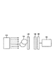
図1に本実施形態に用いられる撮像装置を示す。
本実施形態の撮像装置は、空間的に可干渉なX線を放出するX線源110、X線を回折することで2次元の干渉パターンを形成する第1の格子130、X線を遮蔽する遮蔽部とX線が透過する透過部が2次元周期的に配列された第2の格子140を備えている。
また、第2の格子を経たX線の強度分布を検出する検出器150、検出結果を解析する演算装置160を備えている。
本実施形態の撮像装置は光源としてX線源110を備えている。X線源110から出射したX線は、被検体120を透過すると被検体の屈折率及び形状に応じて位相が変化する。図1では、被検体120をX線源110と第1の格子130の間に配置しているが、第1の格子130と第2の格子140の間に配置しても良い。
第1の格子130は位相格子と呼ばれる透過型の回折格子で、二種類の透過特性を持った箇所が二次元の周期構造を持つように配置されている。そのため、第1の格子を透過したX線は一定の距離を隔てて明部と暗部が2次元周期的に配列された自己像を形成する。
Embodiments of the present invention will be described below in detail with reference to the accompanying drawings.
The imaging apparatus according to the present embodiment uses X-rays having a wavelength of 10 nm or less as light, analyzes a moiré periodic pattern due to Talbot interference by a window Fourier transform method, and obtains a phase image or a differential phase image of a subject.
FIG. 1 shows an imaging apparatus used in this embodiment.
The imaging apparatus according to the present embodiment shields an
Moreover, the
The imaging apparatus of this embodiment includes an
The first grating 130 is a transmission type diffraction grating called a phase grating, and is arranged so that portions having two kinds of transmission characteristics have a two-dimensional periodic structure. For this reason, the X-rays transmitted through the first grating form a self-image in which bright and dark portions are two-dimensionally arranged at regular intervals.
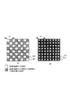
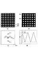
本実施形態に用いられる第1の格子を図2(a)に示す。但し、図2(a)は第1の格子の一部を拡大して示した図である。
図2(a)は一方の領域301を透過したX線が、他方の領域302を透過したX線より位相が相対的にπずれることを特徴とした格子である(π格子)。
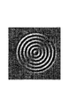
図2(b)は図2(a)の位相格子を用いた時に形成される自己像である。自己像は暗部311と明部312が周期p1で井桁格子状に配置されており、この自己像は2次元に周期を持つ。
但し、図2(b)に示した自己像はX線源と第1の格子の間に被検体が置かれていないときの自己像である。以下、特に断りのない限り、本明細書で自己像の形状について説明する際はX線源と第1の格子の間に被検体が置かれていないときの自己像を指す。
また、本実施形態では図2(a)に示した第1の格子を用いて図2(b)に示した自己像を形成したが、本発明に用いられる第1の格子はこれに限定されず、第1の格子によって形成される自己像もこれに限定されない。
FIG. 2A shows the first grating used in this embodiment. However, FIG. 2A is an enlarged view of a part of the first lattice.
FIG. 2A shows a lattice characterized in that the X-ray transmitted through one
FIG. 2B is a self-image formed when the phase grating shown in FIG. In the self image, the
However, the self-image shown in FIG. 2B is a self-image when the subject is not placed between the X-ray source and the first grating. Hereinafter, unless otherwise specified, when the shape of the self-image is described in the present specification, it refers to a self-image when no subject is placed between the X-ray source and the first grating.
In the present embodiment, the self-image shown in FIG. 2B is formed by using the first grating shown in FIG. 2A, but the first grating used in the present invention is not limited to this. In addition, the self-image formed by the first grating is not limited to this.
X線を用いた位相イメージングを行う場合、第1の格子の周期は数ミクロンメートル程度になる。
これは、タルボ干渉計の場合、第1の格子周期をd、入射光の波長をλ、としたとき、タルボ距離と呼ばれる基本距離zが、
z=d2/2λ ……(1)
で与えられるためである。
実際には第1の格子の形状や所望するコントラストによって(1)式に様々な係数がかかる。
しかし、この(1)式を基準とすると第1の格子と自己像までの距離を装置の大きさと鑑みて数10センチメートル程度にするには、第1の格子の格子周期を数ミクロン程度のオーダーにする必要がある事がわかる。
また、その結果自己像の周期も数ミクロンメートル程度になる。一般的に使用されているX線の検出器の分解能は高くても数10ミクロン程度であり、自己像の周期と差がある。そのためこのままでは自己像が撮像できないため本実施形態の撮像装置ではモアレを利用して自己像を強調している。
When phase imaging using X-rays is performed, the period of the first grating is about several micrometers.
In the case of a Talbot interferometer, when the first grating period is d and the wavelength of incident light is λ, the basic distance z called the Talbot distance is
z = d 2 / 2λ (1)
Because it is given by.
Actually, various coefficients are applied to the equation (1) depending on the shape of the first grating and the desired contrast.
However, on the basis of the equation (1), in order to make the distance from the first grating to the self-image about several tens of centimeters in view of the size of the apparatus, the grating period of the first grating is about several microns. You can see that it needs to be ordered.
As a result, the period of the self-image is about several micrometers. The resolution of a commonly used X-ray detector is about several tens of microns at most, which is different from the period of the self-image. Therefore, since the self-image cannot be picked up as it is, the image pickup apparatus of the present embodiment emphasizes the self-image by using moire.
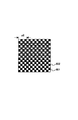
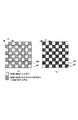
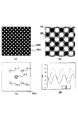
本実施形態では、第2の格子140を用いてモアレを形成している。本実施形態における第2の格子を図3に示す。但し、図3は第2の格子の一部を拡大して示した図である。
第2の格子140はX線を遮蔽する遮蔽部802とX線を透過する透過部801が周期p2で市松格子状に配置されており、第2の格子は2次元に周期を持つ。第2の格子140の周期p2は自己像の周期p1とは僅かに異なっており、周期の差異によって明暗のうねり、すなわちモアレが生じる。
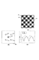
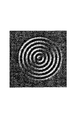
図2(a)に示した第1の格子と図3に示した第2の格子を用いて形成されるモアレを図4(a)に示す。モアレとフーリエ変換については後ほど説明をする。尚、図4(a)に示したモアレはX線源と第1の格子の間または第1の格子と第2の格子の間に被検体が置かれていないときのモアレである。以下、特に断りのない限り、本明細書でモアレ形状について説明する際はX線源と第1の格子の間または第1の格子と第2の格子の間に被検体が置かれていないときのモアレを指す。また、本実施形態では、遮蔽部と透過部が市松格子状に配列された第2の格子140を用いたが、本発明に用いられる第2の格子はこれに限定されない。また、遮蔽部は完全にX線を遮蔽しなくても良いし、透過部は完全にX線を透過しなくても良い。但し、遮蔽部と透過部は自己像に重ねることでモアレを形成することができる程度にX線を遮蔽あるいは透過する必要がある。
In the present embodiment, moire is formed using the
In the
A moire formed using the first grating shown in FIG. 2A and the second grating shown in FIG. 3 is shown in FIG. Moire and Fourier transform will be explained later. Note that the moire shown in FIG. 4A is a moire when the subject is not placed between the X-ray source and the first grating or between the first and second gratings. Unless otherwise specified, when the moire shape is described in the present specification, when the subject is not placed between the X-ray source and the first grating or between the first grating and the second grating. Of moire. Moreover, in this embodiment, the 2nd grating |
検出器150はX線の強度を検出することができる撮像素子(例えばCCD)であり、第2の格子を経たX線の強度分布つまりモアレを検出する。
検出器150が検出したX線の強度分布は演算部160によって解析される。
本実施形態では、窓関数付フーリエ変換法(窓フーリエ変換)に基づいた手法を用いて被検体の位相像又は微分位相像を得る。
窓フーリエ変換とは、モアレに局所的な値を持つ窓関数をかけながら逐次フーリエ変換を行って位相を決定する処理である。この処理はデータ量が多く、時間がかかるものの、窓関数を用いないフーリエ変換法より正確で精密な位相回復が可能である。
The
The X-ray intensity distribution detected by the
In the present embodiment, a phase image or a differential phase image of a subject is obtained using a technique based on a Fourier transform method with a window function (window Fourier transform).
The window Fourier transform is a process of determining the phase by sequentially performing Fourier transform while applying a window function having a local value to the moire. Although this processing requires a large amount of data and takes time, it is possible to perform more accurate and precise phase recovery than the Fourier transform method that does not use a window function.
ここで、フーリエ変換による位相回復方法についてその概念を簡単に説明する。図14はその概略を示す図である。
フーリエ変換法ではモアレをフーリエ成分に分解し、特定の周波数領域に対して解析を行い画像復元する技術である。
図14(a)は解析する前のモアレの一例である。
画面201内に周期的なモアレ202が形成されている。このモアレの位置ずれが被検体によるX線の位相変化に関する情報を表している。
このモアレ202を画面201全体でフーリエ変換すると図14(b)のようになる。
ここでは、波数空間の原点を画面211の中心に置いている。波数空間上では原点に0次スペクトル212が現れ、その周りに1次スペクトルである213、214、215、216が現れる。
原点周りのスペクトルの位置と数はフーリエ変換前のモアレの形状に依存する。このスペクトルのうち少なくとも一つを波面解析に利用する。一般的には1次スペクトル点のどれかを利用する。
Here, the concept of the phase recovery method by Fourier transform will be briefly described. FIG. 14 is a diagram showing the outline.
In the Fourier transform method, moire is decomposed into Fourier components, and analysis is performed on a specific frequency region to restore an image.
FIG. 14A shows an example of moire before analysis.
A
When the
Here, the origin of the wave number space is placed at the center of the
The position and number of the spectrum around the origin depend on the shape of the moire before the Fourier transform. At least one of the spectra is used for wavefront analysis. In general, one of the primary spectral points is used.
非特許文献1に従った方法では、この1次スペクトル点の一点とその周囲をカッティングし、これを別の波数空間221上の原点222に移動させる(図14(c))。
これを逆フーリエ変換することによって被検体の微分像232が実空間231上に取得できる(図14(d))。この微分像232を積分することによって波面を回復する。
上記の方法はフーリエ変換法の一例であって、本発明はこのような解析手法に限定されるものではなく、その他の手法も用いることができる。
例えば、波数空間を更に詳しく解析するために複数のスペクトル点を利用しても良い。
In the method according to
By subjecting this to an inverse Fourier transform, a differential image 232 of the subject can be acquired on the real space 231 (FIG. 14D). The wavefront is recovered by integrating the differential image 232.
The above method is an example of a Fourier transform method, and the present invention is not limited to such an analysis method, and other methods can also be used.
For example, a plurality of spectral points may be used to analyze the wave number space in more detail.
本実施形態において検出したモアレの強度分布から被検体の位相像または微分位相像を得る解析方法について簡単に説明をする。本実施形態におけるモアレ(図4(a))を検出器150の検出面全体でフーリエ変換したものを概略的に表すと図4bの形となる。
図4(b)には波数空間811の中央に0次スペクトル812が、その周りに1次スペクトル813、814、815、816が存在する。
この1次スペクトルから図14で示したように少なくとも一つ以上の任意のスペクトルを解析すると被検体の微分位相像が得られる。また、これを積分すると被検体の位相像が得られる。
An analysis method for obtaining a phase image or a differential phase image of a subject from the moire intensity distribution detected in the present embodiment will be briefly described. A schematic representation of the moire (FIG. 4A) in this embodiment, which is Fourier-transformed over the entire detection surface of the
In FIG. 4B, the zero-
When at least one arbitrary spectrum is analyzed from the primary spectrum as shown in FIG. 14, a differential phase image of the subject is obtained. Further, when this is integrated, a phase image of the subject is obtained.
図4(c)は図4(a)のモアレの軸A1と軸B1に沿ったX線の強度分布を示したもので、軸A1に沿った強度分布を実線、軸B1に沿った強度分布を破線で示した。軸B1は軸A1と平行である。図4(c)に示した通り、軸A1に沿った強度分布と、軸B1に沿った強度分布は形状や振幅は異なるものの、同じ周期を有している。
軸B1以外でも同様に、図4(a)に示したモアレは軸A1と平行な全ての軸に沿った強度分布は、軸A1に沿った強度分布と、同じ周期を有する強度分布が得られる。
つまり、図4(a)の軸A1と平行な方向を第1の方向とすると、図4(a)に示したモアレは第1の方向において、強度分布の周期がモアレ上(検出器の検出面上)の全ての領域で等しい。
また、このモアレは2次元に周期を有しており、軸A1と垂直な軸C1に沿った強度分布も周期を有している。
また、軸A1と同様に軸C1と平行な方向を第2の方向とすると、図4(a)に示したモアレは上記第1の方向と交差する第2の方向において、強度分布の周期がモアレ上の全ての領域で等しい。
但し、本明細書におけるモアレ上の全ての領域とは、波数空間を用いた解析(例えばフーリエ変換)に用いない領域を含まない。
フーリエ変換法では正しくX線の波面微分を計算するために微分方向に沿った断面のX線強度分布の周期が等しいことが必要であり、この強度分布の形状は正弦波の形を有していることがより望ましい。
FIG. 4C shows the X-ray intensity distribution along the moire axes A1 and B1 in FIG. 4A. The intensity distribution along the axis A1 is a solid line and the intensity distribution along the axis B1. Is indicated by a broken line. The axis B1 is parallel to the axis A1. As shown in FIG. 4C, the intensity distribution along the axis A1 and the intensity distribution along the axis B1 have the same period although the shape and amplitude are different.
Similarly to the case other than the axis B1, the moiré shown in FIG. 4A has an intensity distribution along all the axes parallel to the axis A1, and an intensity distribution having the same period as the intensity distribution along the axis A1. .
That is, assuming that the direction parallel to the axis A1 in FIG. 4A is the first direction, the moire shown in FIG. 4A has a period of intensity distribution on the moire in the first direction (detection by the detector). It is the same for all areas on the surface.
The moire has a two-dimensional period, and the intensity distribution along the axis C1 perpendicular to the axis A1 also has a period.
Similarly to the axis A1, when the direction parallel to the axis C1 is the second direction, the moire shown in FIG. 4A has a period of intensity distribution in the second direction intersecting the first direction. Equal in all areas on the moire.
However, all the regions on the moire in this specification do not include regions that are not used for analysis using wave number space (for example, Fourier transform).
In order to correctly calculate the wavefront derivative of X-rays in the Fourier transform method, it is necessary that the period of the X-ray intensity distribution of the cross section along the differential direction is equal, and the shape of this intensity distribution has a sinusoidal shape. It is more desirable.
上述したように、図4(a)の軸A1と平行な方向を第1の方向とすると、図4(a)に示したモアレは第1の方向において、強度分布の周期がモアレ上の全ての領域で等しい。
また、図4(a)の軸C1と平行な方向を第2の方向とすると、図4(a)に示したモアレは第2の方向においても強度分布の周期がモアレ上の全ての領域で等しい。
そのため、第1の方向と第2の方向を微分方向とすると、モアレ上の全ての領域からフーリエ変換によってその周期のスペクトルが抽出できるため、従来と比べて被検体によるX線の位相変化が詳細に解析することが可能となる。尚、微分方向は1つでも良いため、第1の方向又は第2の方向のみを微分方向としても従来(微分方向は1つ)と比べて被検体によるX線の位相変化を詳細に解析することができる。
As described above, when the direction parallel to the axis A1 in FIG. 4A is the first direction, the moire shown in FIG. 4A is the first direction, and the period of the intensity distribution is all over the moire. Equal in the region
Further, if the direction parallel to the axis C1 in FIG. 4A is the second direction, the moire shown in FIG. 4A has the period of the intensity distribution in all areas on the moire also in the second direction. equal.
Therefore, if the first direction and the second direction are differential directions, the spectrum of the period can be extracted from all regions on the moire by Fourier transform, so that the X-ray phase change by the subject is more detailed than in the past. It becomes possible to analyze. Since only one differential direction may be used, even if only the first direction or the second direction is set as the differential direction, the phase change of the X-ray caused by the subject is analyzed in detail as compared with the conventional case (one differential direction). be able to.
以下に、具体的な実施例及び比較例について説明する。
以下の実施例及び比較例では、図13に示すようなシリコン上にパターニングされた厚さ40ミクロンメートルの円形のパターンを被検体として用いた場合に得られる微分位相像を算出し、各実施例と比較例を比較した。
尚、図中ではパターンの高さをコントラストで表現している。
まず、比較例について説明する。
[比較例]
図15を用いて本比較例について説明をする。
本比較例の撮像装置は実施形態で説明した撮像装置と第2の格子が異なり、それ以外の構成は実施形態の撮像装置と同じである。
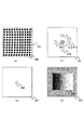
本比較例の撮像装置は光源としては17.5keVの平行X線を出射するX線源、第1の格子としては図2(a)に示した位相格子(π格子)、第2の格子としては図15(a)に示した構造を有する格子を備え、その他に検出器と、演算部を備えている。
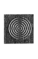
図15(a)は、第2の格子の形状の一部を拡大した概略図である。本比較例の第2の格子は入射したX線が透過する透過部601と、入射したX線が遮蔽する遮蔽部602を有する。第2の格子は第1の格子とは僅かに違う周期を持っており、その差異によって図15(b)に示すようなモアレが生じる。
Specific examples and comparative examples will be described below.
In the following examples and comparative examples, differential phase images obtained when using a circular pattern with a thickness of 40 μm patterned on silicon as shown in FIG. And the comparative example was compared.
In the figure, the height of the pattern is expressed by contrast.
First, a comparative example will be described.
[Comparative example]
This comparative example will be described with reference to FIG.
The imaging device of this comparative example is different from the imaging device described in the embodiment in the second grating, and the other configuration is the same as that of the imaging device of the embodiment.
The imaging apparatus of this comparative example has an X-ray source that emits parallel X-rays of 17.5 keV as a light source, a phase grating (π grating) shown in FIG. 2A as a first grating, and a second grating Includes a grid having the structure shown in FIG. 15A, and further includes a detector and a calculation unit.
FIG. 15A is a schematic view enlarging a part of the shape of the second grating. The second grating of this comparative example includes a
図15(b)に示すモアレをフーリエ変換したものの模式図を図15(c)に示す。
図4(b)と同様に波数空間611の中央に0次スペクトル612と、その周りに1次スペクトル613、614、615、616が存在する。この1次スペクトルから任意のスペクトルを解析し、被検体の微分位相像を算出する。
A schematic diagram of the Fourier transform of the moire shown in FIG. 15B is shown in FIG.
Similar to FIG. 4B, the zero-
図16は、この本比較例で得られた被検体の微分位相像である。
この図では、図13の被検体をx軸(横軸)方向に微分した形状になる。全体的に形状を再現しているが、細かく見ると本来丸いはずの形状に階段状のノイズ(ジャギー)が存在し詳細な形状が再現できていない。
これは第1の格子による自己像と第2の格子の組合せによるモアレの形状が波面の回復に適していないためである。
FIG. 16 is a differential phase image of the subject obtained in this comparative example.
In this figure, the shape in FIG. 13 is differentiated in the x-axis (horizontal axis) direction. The shape is reproduced as a whole, but if you look closely, there is staircase noise (jaggy) in the shape that should be round, but the detailed shape cannot be reproduced.
This is because the shape of the moire resulting from the combination of the self-image of the first grating and the second grating is not suitable for wavefront recovery.
図15(d)は図15aのモアレの軸A5と軸B5に沿ったX線の強度分布を示したもので、軸A5に沿った強度分布を実線、軸B5に沿った強度分布を破線で示した。
軸B5は軸A5と平行である。上述したように、フーリエ変換法では微分方向に沿ったX線強度分布の周期が等しいことが必要である。
図15(d)に示すように、軸A5に沿ったX線の強度分布は三角波の形状を有しておりフーリエ変換を用いた解析可能な周期を持っているが、軸B5に沿ったX線の強度分布は軸上において恒常的に0になっており、このB5の軸に関する波面の情報は得られないことになる。
そのため、波面が詳細に解析できず図16のような全体的に階段状のジャギーが出現する。
FIG. 15D shows the X-ray intensity distribution along the moiré axes A5 and B5 of FIG. 15A. The intensity distribution along the axis A5 is indicated by a solid line, and the intensity distribution along the axis B5 is indicated by a broken line. Indicated.
The axis B5 is parallel to the axis A5. As described above, the Fourier transform method requires that the periods of the X-ray intensity distribution along the differential direction are equal.
As shown in FIG. 15D, the X-ray intensity distribution along the axis A5 has a triangular wave shape and has a period that can be analyzed using the Fourier transform, but the X-ray intensity distribution along the axis B5. The intensity distribution of the line is constantly 0 on the axis, and information on the wavefront relating to the B5 axis cannot be obtained.
Therefore, the wavefront cannot be analyzed in detail, and an overall step-like jaggy as shown in FIG. 16 appears.
[実施例1]
図4を用いて実施例1について説明をする。
実施例1は実施形態で説明をした撮像装置と同じ構成であり、比較例とは第2の格子が異なる。つまり、本実施例の撮像装置の光源は17.5keVの平行X線を出射するX線源、第1の格子は図2(a)に示した位相格子、第2の格子は図3に示した構造を有する格子であり、その他に検出器と、演算部を備えている。上述した通り、第2の格子の周期p2は第1の格子の周期p1とは僅かに異なっており、その差異によって図4(a)に示したようなモアレが形成され、このモアレをフーリエ変換したものが図4(b)、モアレ上の軸A1、軸B1に沿ったX線の強度分布が図4(c)の実線と破線である。
図4(b)の1次スペクトル813、814、815、816から任意のスペクトルを1つ選び、解析し、被検体の微分位相像を算出する。
図5は本実施例で得られた微分位相像である。
比較例と比べると、1次スペクトルの位置が斜め45度方向にあるため、微分位相像も図16と比べると斜め45度に傾いている。しかし、その違いを除くと図16の微分位相像に比べてエッジのジャギーが目立たず、詳細な形状再現できている。
[Example 1]
Example 1 will be described with reference to FIG.
Example 1 has the same configuration as the imaging device described in the embodiment, and the second grating is different from the comparative example. That is, the light source of the image pickup apparatus of this embodiment is an X-ray source that emits parallel X-rays of 17.5 keV, the first grating is the phase grating shown in FIG. 2A, and the second grating is shown in FIG. In addition, the grid has a detector and a calculation unit. As described above, the period p2 of the second grating is slightly different from the period p1 of the first grating, and the moire as shown in FIG. 4A is formed by the difference, and this moire is Fourier transformed. FIG. 4B shows the X-ray intensity distribution along the axis A1 and the axis B1 on the moire as indicated by the solid line and the broken line in FIG.
One arbitrary spectrum is selected from the
FIG. 5 is a differential phase image obtained in this example.
Compared to the comparative example, since the position of the primary spectrum is in the direction of 45 degrees obliquely, the differential phase image is also inclined to 45 degrees obliquely compared to FIG. However, excluding the difference, edge jaggies are not conspicuous compared to the differential phase image of FIG. 16, and a detailed shape can be reproduced.
上述の通り、図4(c)は図4(a)のモアレの軸A1と軸B1に沿ったX線の強度分布を示したもので、軸A1に沿った強度分布と、軸B1に沿った強度分布は形状や振幅は異なるものの、同じ周期を有している。
軸B1以外でも同様であり、図4(a)の軸A1と平行な方向を第1の方向とすると、図4(a)に示したモアレは第1の方向において、強度分布の周期がモアレ上の全ての領域で等しい。
そのため、第1の方向を微分方向とすると、モアレ上の全ての領域からフーリエ変換によってその周期のスペクトルが抽出できるため波面を詳細に解析することができ、比較例と比べて詳細な形状を解析することが可能となる。
As described above, FIG. 4C shows the X-ray intensity distribution along the moiré axes A1 and B1 of FIG. 4A, and the intensity distribution along the axis A1 and along the axis B1. The intensity distribution has the same period although the shape and amplitude are different.
The same applies to other than the axis B1, and when the direction parallel to the axis A1 in FIG. 4A is the first direction, the moire shown in FIG. Equal in all areas above.
Therefore, if the first direction is the differential direction, the spectrum of the period can be extracted from all regions on the moire by Fourier transform, so that the wavefront can be analyzed in detail, and the detailed shape compared with the comparative example It becomes possible to do.
[実施例2]
実施例2として、半透過部を有する第2の格子を用いた撮像装置について図6を用いて説明する。実施例2の撮像装置は、第2の格子以外は実施例1と同様の構造を持つ。
本実施例の第2の格子の構造を図6(a)に示す。図6(a)は第2の格子の形状の一部を拡大した模式図である。1001は入射したX線の透過部を表し、1002は遮蔽部を表す。
更に、本実施例に用いられる第2の格子には入射したX線のうち50%が透過するような半透過部1003が存在する。
本実施例の半透過部をX線が透過すると、入射したX線の強度は半分になるが、遮蔽部よりもX線を透過させ、透過部よりもX線を遮蔽すれば良い。
本実施例の第2の格子は、遮蔽部と、透過部と、半透過部が図6(a)に示すように夫々市松格子状に配列されており、遮蔽部と、透過部と、半透過部がいわゆるベイヤ配列に配置されている。
実施例1と同様に第2の格子の周期は自己像の周期と僅かに異なり、その差異によって図6(b)に示すようなモアレが形成される。
実施例1同様、このモアレをフーリエ変換したものが図6(c)、モアレ上の軸A2に沿ったX線の強度分布が図6(d)の実線、軸B2に沿ったX線の強度分布が図6(d)の破線である。
[Example 2]
As Example 2, an imaging apparatus using a second grating having a semi-transmissive portion will be described with reference to FIG. The imaging apparatus of the second embodiment has the same structure as that of the first embodiment except for the second grating.
The structure of the second grating in this example is shown in FIG. FIG. 6A is a schematic diagram enlarging a part of the shape of the second grating.
Further, the second grating used in this embodiment has a
When X-rays are transmitted through the semi-transmissive part of this embodiment, the intensity of the incident X-rays is halved. However, X-rays may be transmitted through the shielding part and shielded from the transmissive part.
In the second grating of this embodiment, the shielding part, the transmissive part, and the semi-transmissive part are each arranged in a checkered pattern as shown in FIG. 6A, and the shielding part, the transmissive part, and the semi-transmissive part are arranged. The transmission parts are arranged in a so-called Bayer array.
Similar to the first embodiment, the period of the second grating is slightly different from the period of the self-image, and a moire as shown in FIG. 6B is formed by the difference.
As in Example 1, the result of Fourier transform of this moire is FIG. 6C, and the X-ray intensity distribution along the axis A2 on the moire is the solid line in FIG. 6D, and the X-ray intensity along the axis B2. The distribution is a broken line in FIG.
図6(b)に示したモアレをフーリエ変換すると図6(c)の様なスペクトルが出現する。
図4(b)と同様に、図6(c)も波数空間1011の中央に0次スペクトル1012、その周りに1次スペクトル1013、1014、1015、1016が存在する。
図6(c)の1次スペクトル1013、1014、1015、1016から任意のスペクトルを1つ選び、解析し、被検体の微分位相像を算出する。
図7は本実施例で得られた微分位相像である。
比較例と同じ位置に1次スペクトルが現れており、図16の微分位相像に比べてエッジのジャギーが目立たず、詳細な形状再現できている。
When the moire shown in FIG. 6B is Fourier transformed, a spectrum as shown in FIG. 6C appears.
Similar to FIG. 4B, FIG. 6C also has a zero-
One arbitrary spectrum is selected from the
FIG. 7 is a differential phase image obtained in this example.
A primary spectrum appears at the same position as in the comparative example, and edge jaggies are not noticeable compared to the differential phase image of FIG. 16, and a detailed shape can be reproduced.
図6(d)は図6(b)のモアレの軸A2と軸B2に沿ったX線の強度分布を示したものである。図4(a)のモアレ同様、図6(b)のモアレも軸A2と平行な方向を第1の方向とすると、第1の方向において強度分布の周期がモアレ上の全ての領域で等しいため、実施例1同様、比較例と比べて詳細な形状を解析することが可能となる。
また、図4(a)のモアレとは異なり、図6に示す軸B2のモアレは第1の方向において強度分布が振幅や形状も揃っており、モアレ上の全ての領域で同じパターンが同じ周期で繰り返されている。そのため、フーリエ変換によってその周期のスペクトルの抽出が容易にできる。
FIG. 6D shows an X-ray intensity distribution along the axes A2 and B2 of the moire in FIG. 6B. Similar to the moire in FIG. 4 (a), the moire in FIG. 6 (b) also has a period of intensity distribution equal in all areas on the moire in the first direction when the direction parallel to the axis A2 is the first direction. Like Example 1, it becomes possible to analyze a detailed shape compared with a comparative example.
Also, unlike the moiré shown in FIG. 4A, the moiré of the axis B2 shown in FIG. 6 has the same intensity distribution and amplitude and shape in the first direction, and the same pattern has the same period in all areas on the moiré. Is repeated. Therefore, the spectrum of the period can be easily extracted by Fourier transform.
[実施例3]
実施例3では実施例1の撮像装置と異なる自己像を形成する撮像装置について図8と図9を用いて説明する。実施例3の撮像装置は、第1の格子と第2の格子以外は実施例1と同様の構造を持つ。
本実施例に用いた第1の格子を図8(a)に示した。但し、図8(a)は第1の格子の一部を拡大した概略図である。
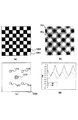
図8(a)は一方の領域401を透過したx線が、他方の領域402を透過したx線より位相が相対的にπ/2ずれることを特徴とした格子である(π/2格子)。また、図8(b)は図8aの位相格子を用いた時に形成される自己像である。自己像は暗部411と明部412が周期市松格子(チェッカーボード)状に配置されており、この自己像は2次元に周期を持つ。
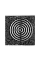
本実施例に用いた第2の格子を図9(a)に示した。但し、図9(a)は第2の格子の一部を拡大した概略図である。本実施例に用いた第2の格子はX線を透過する透過部1201と、X線を遮蔽する遮蔽部1202が市松格子状に配置されている。第2の格子は第1の格子とは僅かに違う周期を持っており、その差異によって図9(b)に示したようなモアレが生じる。実施例1同様、このモアレをフーリエ変換したものが図9(c)、モアレ上の軸A3に沿ったX線の強度分布が図9(d)の実線、軸B3に沿ったX線の強度分布が図9(d)の破線である。
[Example 3]
In the third embodiment, an imaging apparatus that forms a self-image different from the imaging apparatus of the first embodiment will be described with reference to FIGS. 8 and 9. The imaging apparatus according to the third embodiment has the same structure as that of the first embodiment except for the first grating and the second grating.
FIG. 8A shows the first grating used in this example. However, FIG. 8A is a schematic view in which a part of the first lattice is enlarged.
FIG. 8A shows a lattice characterized in that the phase of x-rays transmitted through one
FIG. 9A shows the second grating used in this example. However, FIG. 9A is an enlarged schematic view of a part of the second lattice. In the second grating used in this embodiment, a transmission part 1201 that transmits X-rays and a
図9(b)に示したモアレをフーリエ変換すると図9(c)の様なスペクトルが出現する。図4(b)と同様に、同様に、波数空間1203の中央に0次スペクトル1204とその周りに1次スペクトル1205、1206、1207、1208が存在する。
図10は本実施例で得られた微分位相像である。
比較例と比べると、1次スペクトルの位置が斜め45度方向にあるため、微分位相像も図16と比べると斜め45度に傾いている。しかし、その違いを除くと図16の微分位相像に比べてエッジのジャギーが目立たず、詳細な形状が再現できている。
図9(d)は図9(b)のモアレの軸A3と軸B3に沿ったX線の強度分布を示したものである。図4(a)のモアレ同様、図9(b)のモアレも軸A3と平行な方向を第1の方向とすると、第1の方向において強度分布の周期がモアレ上の全ての領域で等しいため、実施例1同様、比較例と比べて詳細な形状を解析することが可能となる。
When the moire shown in FIG. 9B is Fourier transformed, a spectrum as shown in FIG. 9C appears. Similarly to FIG. 4B, similarly, a zero-
FIG. 10 is a differential phase image obtained in this example.
Compared to the comparative example, since the position of the primary spectrum is in the direction of 45 degrees obliquely, the differential phase image is also inclined to 45 degrees obliquely compared to FIG. However, excluding the difference, edge jaggies are not noticeable compared to the differential phase image of FIG. 16, and a detailed shape can be reproduced.
FIG. 9D shows the X-ray intensity distribution along the moiré axes A3 and B3 of FIG. 9B. Similar to the moire in FIG. 4A, the moire in FIG. 9B also assumes that the first direction is the direction parallel to the axis A3, and the period of the intensity distribution in the first direction is the same in all regions on the moire. Like Example 1, it becomes possible to analyze a detailed shape compared with a comparative example.
[実施例4]
実施例4では実施例3と同じ第1の格子を用いる撮像装置について図11を用いて説明をする。本実施例は実施例3と用いる第2の格子が異なり、その他の構成は同じである。
図11(a)は第2の格子の一部を拡大した概略図である。
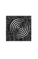
本実施例に用いられる第2の格子はX線の透過部1401と遮蔽部1402が井桁格子状に配置されたものが自己像に対して45°回転したような形状を有している。第2の格子は第1の格子とは僅かに違う周期を持っており、その差異によって図11(b)に示したようなモアレが生じる。実施例1同様、このモアレをフーリエ変換したものが図11(c)、モアレ上の軸A4に沿ったX線の強度分布が図11(d)の実線、軸B4に沿ったX線の強度分布が図11(d)の破線である。
[Example 4]
In the fourth embodiment, an imaging apparatus using the same first grating as that of the third embodiment will be described with reference to FIG. The second embodiment is different from the third embodiment in the second lattice, and the other configurations are the same.
FIG. 11A is a schematic view enlarging a part of the second grating.
The second grating used in this embodiment has such a shape that an
図11(b)に示したモアレをフーリエ変換すると図11(c)の様なスペクトルが出現する。図4(b)と同様に、図11(c)も波数空間に波数空間1411の中央に0次スペクトル1412とその周りに1次スペクトル1413、1414、1415、1416が存在する。
図10は本実施例で得られた微分位相像である。
比較例と比べると、1次スペクトルの位置が斜め45度方向にあるため、微分位相像も図16と比べると斜め45度に傾いている。しかし、その違いを除くと図16の微分位相像に比べてエッジのジャギーが低減しており、滑らかな曲面が表現されている。
図11(d)は図11(b)のモアレの軸A4と軸B4に沿ったX線の強度分布を示したものである。図4(a)のモアレ同様、図11(b)のモアレも軸A4と平行な方向を第1の方向とすると、第1の方向において強度分布の周期がモアレ上の全ての領域で等しいため、実施例1同様、比較例と比べて詳細な形状を解析することが可能となる。
また、強度分布の周期の形状が実施例の中で最もサインカーブに近い。これはフーリエ変換した際にノイズとなる高次のスペクトルが出現しにくいことを示しており、この点においてこの実施例4は波面解析においては実施例1〜3よりも適している。
When the moire shown in FIG. 11B is Fourier transformed, a spectrum as shown in FIG. 11C appears. Similar to FIG. 4B, FIG. 11C also has a zero-
FIG. 10 is a differential phase image obtained in this example.
Compared to the comparative example, since the position of the primary spectrum is in the direction of 45 degrees obliquely, the differential phase image is also inclined to 45 degrees obliquely compared to FIG. However, excluding the difference, edge jaggy is reduced as compared with the differential phase image of FIG. 16, and a smooth curved surface is expressed.
FIG. 11D shows the X-ray intensity distribution along the axes A4 and B4 of the moire in FIG. 11B. Similar to the moire in FIG. 4A, the moire in FIG. 11B also assumes that the period parallel to the axis A4 is the first direction, and the period of the intensity distribution in the first direction is the same in all regions on the moire. Like Example 1, it becomes possible to analyze a detailed shape compared with a comparative example.
Further, the shape of the period of the intensity distribution is closest to the sine curve in the embodiments. This indicates that a high-order spectrum that becomes noise upon Fourier transform hardly appears, and in this respect, the fourth embodiment is more suitable than the first to third embodiments in wavefront analysis.
110:X線源
120:被検体
130:第1の格子
140:第2の格子
150:検出器
160:演算部
110: X-ray source 120: Subject 130: First grating 140: Second grating 150: Detector 160: Calculation unit
Claims (12)
前記光を遮蔽する遮蔽部と前記光を透過する透過部とが2次元に配列されており、前記干渉パターンの一部を遮蔽する第2の格子と、
前記第2の格子を経た前記光を検出する検出器と、
前記検出器で検出した前記光の強度分布の周期的パターンに基づいて被検体の位相像又は微分位相像を算出する演算部と、を備え、
第1の方向における前記強度分布の周期が前記検出器の検出面上の全ての領域で等しくなるように、前記第1の格子と前記第2の格子とが構成されていることを特徴とする撮像装置。 A first grating that forms a two-dimensional interference pattern by diffracting light from a light source;
A shielding part that shields the light and a transmission part that transmits the light are two-dimensionally arranged; and a second grating that shields a part of the interference pattern;
A detector for detecting the light having passed through the second grating;
A calculation unit that calculates a phase image or a differential phase image of the subject based on a periodic pattern of the intensity distribution of the light detected by the detector, and
The first grating and the second grating are configured so that the period of the intensity distribution in the first direction is equal in all regions on the detection surface of the detector. Imaging device.
前記第1の方向及び前記第2の方向は前記微分位相像の微分方向であることを特徴とする請求項2から5のいずれか1項に記載の撮像装置。 The calculation unit calculates the differential phase image of the subject,
The imaging apparatus according to claim 2, wherein the first direction and the second direction are differential directions of the differential phase image.
前記光を遮蔽する遮蔽部と透過する透過部とが2次元に配列されており、前記干渉パターンの一部を遮蔽する第2の格子と、
前記第2の格子を経た前記光を検出する検出器と、
前記検出器で検出した前記光の強度分布の周期的パターンに基づいて被検体の位相像又は微分位相像を算出する演算部と、を備え、
前記干渉パターンは井桁格子状のパターンであり、
前記第2の格子は、前記遮蔽部と前記透過部とが市松格子状に配置されていることを特徴とする撮像装置。 A first grating that forms a two-dimensional interference pattern by diffracting light from a light source;
A shielding part that shields the light and a transmission part that transmits the light are two-dimensionally arranged; a second grating that shields a part of the interference pattern;
A detector for detecting the light having passed through the second grating;
A calculation unit that calculates a phase image or a differential phase image of the subject based on a periodic pattern of the intensity distribution of the light detected by the detector, and
The interference pattern is a grid pattern.
The image pickup apparatus, wherein the second grating has the shielding part and the transmission part arranged in a checkered pattern.
前記光を遮蔽する遮蔽部と透過する透過部とが2次元に配列されており、前記干渉パターンの一部を遮蔽する第2の格子と、
前記第2の格子を経た前記光を検出する検出器と、
前記検出器で検出した前記光の強度分布の周期的パターンに基づいて被検体の位相像又は微分位相像を算出する演算部と、を備え、
前記干渉パターンは井桁格子状のパターンであり、
前記第2の格子は、前記遮蔽部と、前記透過部と、前記遮蔽部よりも光を透過させ、前記透過部よりも光を遮蔽する半透過部とを有し、
前記遮蔽部と前記透過部と前記半透過部とが夫々市松格子状に並んだベイヤ配列に配置されていることを特徴とする撮像装置。 A first grating that forms a two-dimensional interference pattern by diffracting light from a light source;
A shielding part that shields the light and a transmission part that transmits the light are two-dimensionally arranged; a second grating that shields a part of the interference pattern;
A detector for detecting the light having passed through the second grating;
A calculation unit that calculates a phase image or a differential phase image of the subject based on a periodic pattern of the intensity distribution of the light detected by the detector, and
The interference pattern is a grid pattern.
The second grating includes the shielding part, the transmission part, and a semi-transmission part that transmits light more than the shielding part and shields light from the transmission part.
An imaging apparatus, wherein the shielding part, the transmissive part, and the semi-transmissive part are arranged in a Bayer array in which the shielding part, the transmissive part, and the semi-transmissive part are arranged in a checkered pattern.
前記光を遮蔽する遮蔽部と透過する透過部とが2次元に配列されており、前記干渉パターンの一部を遮蔽する第2の格子と、
前記第2の格子を経た前記光を検出する検出器と、
前記検出器で検出した前記光の強度分布の周期的パターンに基づいて被検体の位相像又は微分位相像を算出する演算部と、を備え、
前記干渉パターンは市松格子状のパターンであり、
前記第2の格子は、前記遮蔽部と前記透過部とが市松格子状に配置されていることを特徴とする撮像装置。 A first grating that forms a two-dimensional interference pattern by diffracting light from a light source;
A shielding part that shields the light and a transmission part that transmits the light are two-dimensionally arranged; a second grating that shields a part of the interference pattern;
A detector for detecting the light having passed through the second grating;
A calculation unit that calculates a phase image or a differential phase image of the subject based on a periodic pattern of the intensity distribution of the light detected by the detector, and
The interference pattern is a checkered pattern,
The image pickup apparatus, wherein the second grating has the shielding part and the transmission part arranged in a checkered pattern.
前記光を遮蔽する遮蔽部と透過する透過部とが2次元に配列されており、前記干渉パターンの一部を遮蔽する第2の格子と、
前記第2の格子を経た前記光を検出する検出器と、
前記検出器で検出した前記光の強度分布の周期的パターンに基づいて被検体の位相像又は微分位相像を算出する演算部と、を備え、
前記干渉パターンは市松格子状のパターンであり、
前記第2の格子は、前記遮蔽部と前記透過部とが井桁格子状に配置されていることを特徴とする撮像装置。 A first grating that forms a two-dimensional interference pattern by diffracting light from a light source;
A shielding part that shields the light and a transmission part that transmits the light are two-dimensionally arranged; a second grating that shields a part of the interference pattern;
A detector for detecting the light having passed through the second grating;
A calculation unit that calculates a phase image or a differential phase image of the subject based on a periodic pattern of the intensity distribution of the light detected by the detector, and
The interference pattern is a checkered pattern,
In the second grating, the shielding unit and the transmission unit are arranged in a grid pattern.
前記光を遮蔽する遮蔽部と前記光を透過する透過部とが2次元に配列されている第2の格子により前記干渉パターンの一部が遮蔽される工程と、
前記第2の格子を経た光の強度分布が検出器により検出される工程と、
前記検出器により検出された前記強度分布の周期的パターンを前記演算部により解析して被検体の位相像又は微分位相像を算出する工程と、を備え、
第1の方向における前記強度分布の周期を前記検出器の検出面上において一定とし、
且つ、第2の方向における前記強度分布の周期が前記検出器の前記検出面上において一定であるように前記第1の格子と前記第2の格子とを構成して前記被検体を位相像又は微分位相像を取得することを特徴とする撮像方法。 Forming a two-dimensional interference pattern by the first grating diffracting light;
A part of the interference pattern is shielded by a second grating in which a shielding part that shields the light and a transmission part that transmits the light are two-dimensionally arranged;
A step of detecting a light intensity distribution through the second grating by a detector;
Analyzing the periodic pattern of the intensity distribution detected by the detector by the calculation unit to calculate a phase image or a differential phase image of the subject, and
The period of the intensity distribution in the first direction is constant on the detection surface of the detector,
In addition, the first grating and the second grating are configured so that the period of the intensity distribution in the second direction is constant on the detection surface of the detector, so that the subject is a phase image or An imaging method characterized by acquiring a differential phase image.
Priority Applications (1)
| Application Number | Priority Date | Filing Date | Title |
|---|---|---|---|
| JP2011062025A JP2011237773A (en) | 2010-04-12 | 2011-03-22 | Imaging apparatus and imaging method |
Applications Claiming Priority (3)
| Application Number | Priority Date | Filing Date | Title |
|---|---|---|---|
| JP2010091562 | 2010-04-12 | ||
| JP2010091562 | 2010-04-12 | ||
| JP2011062025A JP2011237773A (en) | 2010-04-12 | 2011-03-22 | Imaging apparatus and imaging method |
Publications (1)
| Publication Number | Publication Date |
|---|---|
| JP2011237773A true JP2011237773A (en) | 2011-11-24 |
Family
ID=45325764
Family Applications (1)
| Application Number | Title | Priority Date | Filing Date |
|---|---|---|---|
| JP2011062025A Withdrawn JP2011237773A (en) | 2010-04-12 | 2011-03-22 | Imaging apparatus and imaging method |
Country Status (1)
| Country | Link |
|---|---|
| JP (1) | JP2011237773A (en) |
Cited By (1)
| Publication number | Priority date | Publication date | Assignee | Title |
|---|---|---|---|---|
| JP2014117336A (en) * | 2012-12-13 | 2014-06-30 | Canon Inc | Arithmetic unit, program and imaging system |
-
2011
- 2011-03-22 JP JP2011062025A patent/JP2011237773A/en not_active Withdrawn
Cited By (1)
| Publication number | Priority date | Publication date | Assignee | Title |
|---|---|---|---|---|
| JP2014117336A (en) * | 2012-12-13 | 2014-06-30 | Canon Inc | Arithmetic unit, program and imaging system |
Similar Documents
| Publication | Publication Date | Title |
|---|---|---|
| US8559594B2 (en) | Imaging apparatus and imaging method | |
| JP5538936B2 (en) | Analysis method, program, storage medium, X-ray phase imaging apparatus | |
| KR101258927B1 (en) | X-ray imaging device and x-ray imaging method | |
| JP5777360B2 (en) | X-ray imaging device | |
| CN102914374B (en) | Wavefront measuring apparatus and wavefront measuring method | |
| JP5875280B2 (en) | Imaging device using Talbot interference and method for adjusting imaging device | |
| JP2014171799A (en) | X-ray imaging apparatus, and x-ray imaging system | |
| JP6537293B2 (en) | X-ray Talbot interferometer and X-ray Talbot interferometer system | |
| JP2013063099A (en) | X-ray imaging device | |
| JP5868132B2 (en) | Imaging apparatus and image processing method | |
| JP5885405B2 (en) | Imaging apparatus, interference fringe analysis program, and interference fringe analysis method | |
| JP6566839B2 (en) | X-ray Talbot interferometer and Talbot interferometer system | |
| WO2015156379A1 (en) | Image processing unit and control method for image processing unit | |
| JP2016106721A (en) | Image processing device and image processing method | |
| JP6604772B2 (en) | X-ray Talbot interferometer | |
| JP2011237773A (en) | Imaging apparatus and imaging method | |
| JP2014006247A (en) | Specimen information acquisition device, specimen information acquisition method, and program | |
| Singh et al. | Application of wavelet filtering techniques to Lau interferometric fringe analysis for measurement of small tilt angles | |
| JP2013042983A (en) | Tomosynthesis imaging device and imaging method of tomosynthesis image | |
| JP2015227784A (en) | Interferometer |
Legal Events
| Date | Code | Title | Description |
|---|---|---|---|
| RD01 | Notification of change of attorney |
Free format text: JAPANESE INTERMEDIATE CODE: A7421 Effective date: 20131212 |
|
| A300 | Withdrawal of application because of no request for examination |
Free format text: JAPANESE INTERMEDIATE CODE: A300 Effective date: 20140603 |