JP2011237682A - Display device - Google Patents
Display device Download PDFInfo
- Publication number
- JP2011237682A JP2011237682A JP2010110448A JP2010110448A JP2011237682A JP 2011237682 A JP2011237682 A JP 2011237682A JP 2010110448 A JP2010110448 A JP 2010110448A JP 2010110448 A JP2010110448 A JP 2010110448A JP 2011237682 A JP2011237682 A JP 2011237682A
- Authority
- JP
- Japan
- Prior art keywords
- screen
- spherical
- display device
- projector
- optical path
- Prior art date
- Legal status (The legal status is an assumption and is not a legal conclusion. Google has not performed a legal analysis and makes no representation as to the accuracy of the status listed.)
- Pending
Links
Images


Landscapes
- Instruments For Viewing The Inside Of Hollow Bodies (AREA)
- Lenses (AREA)
- Projection Apparatus (AREA)
- Endoscopes (AREA)
Abstract
Description
本発明は、外側がつるつる面で内側が拡散面となっているスクリーンに、スクリーンの内側に配置された投影光学系を経てプロジェクターから投影された画像を表示し、その画像をスクリーンの外部から観察するようにした表示装置に関するものである。 The present invention displays an image projected from a projector via a projection optical system disposed inside the screen on a screen having a smooth surface on the outside and a diffusion surface on the inside, and the image is observed from outside the screen. The present invention relates to a display device.
また、スクリーンを回転させると、プロジェクターから投影される画像も回転し、回転角に応じてスクリーンに画像が表示されるようにした表示装置に関するものである。 Further, the present invention relates to a display device in which when the screen is rotated, the image projected from the projector is also rotated, and the image is displayed on the screen according to the rotation angle.
拡散面にプロジェクターから投影された画像を表示し、その画像を球面状や曲面状の透明体の外部から観察するようにした表示装置としては、例えば特許文献1や特許文献2に示すようなものがある。
As a display device that displays an image projected from a projector on a diffusion surface and observes the image from the outside of a spherical or curved transparent body, for example, as shown in
特許文献1に示すものは、図18に示すように、透明球aの内部に拡散面bを設け、拡散面bにハーフミラーcの下方に設けたプロジェクターdの投写画像を投写し、透明球aの凸レンズとしての働きにより拡大虚像として視点eから観察するようにしたものである。 As shown in FIG. 18, as shown in FIG. 18, a diffusing surface b is provided inside a transparent sphere a, and a projection image of a projector d provided below the half mirror c is projected on the diffusing surface b. The enlarged virtual image is observed from the viewpoint e by the function of a as a convex lens.
特許文献2に示すものは、図19に示すように、透明球aの一部または近接させて拡散面bを設け、拡散面bにハーフミラーcの下方に設けたプロジェクターdの投写画像を投写し、透明球aの凸レンズとしての働きにより拡大虚像として視点eから観察するようにしたものである。
As shown in
しかし、上記特許文献1及び特許文献2に示すものでは小さい像を結像して透明球を拡大鏡として用いて観察する方法であるため、視点位置が限定される。さらに、遠くから投影しているので効率も悪い。また、透明球を拡大鏡として用いているので、周辺画像が劣化し、また画像も歪む。その上、大がかりで、プロジェクターを設置するスペースも大きくなり厚いものとなり、ハーフミラーを用いることにより光量ロスにつながる、という問題がある。
However, since the methods disclosed in
本発明は、上記課題に鑑みてなされたものであり、視点方向どこからでもほぼ均等に明るく歪まない画像が見え、さらに周辺画質が良いので球面のギリギリまで画像が良く見える。また、薄型で省スペースであり、球面表示部を回転させられるようにすることにより各種用途に適用できる表示装置を提供することを目的としている。 The present invention has been made in view of the above-mentioned problems. An image that is bright and undistorted almost uniformly from any direction in the viewpoint can be seen. Further, since the peripheral image quality is good, the image can be seen well up to a spherical limit. Another object of the present invention is to provide a display device that is thin and space-saving and can be applied to various applications by allowing the spherical display portion to rotate.
上記の目的を達成するために、本発明による表示装置は、スクリーンと、スクリーンの内側に配置された投影光学系と、光路を折り曲げる光学系と、プロジェクターと、からなり、スクリーンは外側表面がつるつる面で内面が拡散面からなる透明部材であることを特徴としている。 In order to achieve the above object, a display device according to the present invention includes a screen, a projection optical system disposed inside the screen, an optical system that bends an optical path, and a projector, and the screen has a smooth outer surface. It is a transparent member whose inner surface is a diffusion surface.
また、本発明の表示装置においては、前記スクリーンは、平らな板状であることが好ましい。 In the display device of the present invention, it is preferable that the screen has a flat plate shape.
また、本発明の表示装置においては、前記スクリーンは、任意の曲面部を有する形状であることが好ましい。 In the display device of the present invention, it is preferable that the screen has a shape having an arbitrary curved surface portion.
あるいは、本発明の表示装置は、内視鏡の操作部又は本体部に取り付け可能な請求項1〜3の何れかに記載した表示装置であって、前記スクリーンを回転させると、その回転角を検出して回転角に応じて内視鏡の撮像手段が回動させられることを特徴としている。
Alternatively, the display device according to the present invention is the display device according to any one of
あるいは、本発明の表示装置は、スクリーンは球面状スクリーンであって、スクリーンの内側となる球心側に配置された放射状の光路を有する投影光学系と、プロジェクターと、からなることを特徴としている。 Alternatively, the display device according to the present invention is characterized in that the screen is a spherical screen, and includes a projection optical system having a radial optical path disposed on the inner side of the screen and a projector, and a projector. .
また、本発明の表示装置においては、前記球面状スクリーンは、外側表面がつるつる面でほぼ同心の内面球面が拡散面の透明部材からなるほぼ球面の中空構造のスクリーンであることが好ましい。 In the display device of the present invention, it is preferable that the spherical screen is a screen having a hollow structure in which an outer surface is a smooth surface and a substantially concentric inner spherical surface is formed of a transparent member having a diffusing surface.
また、本発明の表示装置においては、放射状の光路を有する光学系の射出瞳(EP)位置は、球心点を0(ゼロ)とし、前記内面球面の位置をRとすると、
+R/2>EP>−2R
であることが好ましい。
In the display device of the present invention, the exit pupil (EP) position of the optical system having a radial optical path is set to 0 (zero) as the spherical center and R as the position of the inner spherical surface.
+ R / 2>EP> -2R
It is preferable that
また、本発明の表示装置においては、前記投影光学系は、画角(2ω)は80度〜300度であり、前記プロジェクターの光路を拡大するアフォーカル光学系からなることが好ましい。 In the display device of the present invention, it is preferable that the projection optical system has an angle of view (2ω) of 80 degrees to 300 degrees and an afocal optical system that expands the optical path of the projector.
また、本発明の表示装置においては、前記投影光学系は、画角(2ω)は80度〜300度であり、前記プロジェクターから投射された画像が結像レンズで一度中間像を結像したのち、投影レンズで拡大投影されるように構成されていることが好ましい。 In the display device of the present invention, the projection optical system has an angle of view (2ω) of 80 ° to 300 °, and the image projected from the projector forms an intermediate image once with an imaging lens. The projection lens is preferably configured to be enlarged and projected.
また、本発明の表示装置においては、光路を折り曲げる光学系を備えることが好ましい。 The display device of the present invention preferably includes an optical system that bends the optical path.
また、本発明の表示装置においては、2個の前記球面状スクリーンが軸まわりに回転可能に相対して配置され、一方の前記球面状スクリーンを回転すると、他方の前記球面状スクリーンも同様に回転するとともに、前記光路を折り曲げる光学系をプリズムで構成し、該プリズムの光路が確保されるように、それぞれの前記球面状スクリーンの回転角が設定されていることが好ましい。 In the display device of the present invention, the two spherical screens are arranged so as to be rotatable around an axis, and when one of the spherical screens is rotated, the other spherical screen is similarly rotated. In addition, it is preferable that the optical system for bending the optical path is constituted by a prism, and the rotation angle of each spherical screen is set so that the optical path of the prism is secured.
あるいは、本発明の表示装置は、2個の球面状スクリーンが軸まわりに回転可能に平板状部材を挟んで相対して連結部材により連結されて配置され、一方の球面状スクリーンを軸まわりに回転すると、他方の球面状スクリーンも同様に回転し、前記平板状部材内に1つ又は2つのプロジェクターが内蔵され、前記プロジェクターからの光束が光路偏向プリズムで前記球面状スクリーンに投射され、前記球面状スクリーンの回転角(φ)は、0度<φ<350度であり、前記プロジェクターからの光路をケラないように前記連結部材には切り欠き部が形成されていることを特徴としている。 Alternatively, in the display device of the present invention, two spherical screens are arranged to be connected to each other by a connecting member facing each other with a flat plate member interposed between them so that the spherical screen can be rotated about the axis. Then, the other spherical screen rotates in the same manner, and one or two projectors are built in the flat plate-like member, and a light beam from the projector is projected onto the spherical screen by an optical path deflecting prism. The rotation angle (φ) of the screen is 0 ° <φ <350 °, and the connection member is formed with a notch so as not to vignett the optical path from the projector.
あるいは、本発明の表示装置は、台座内にプロジェクターと偏向プリズムが設けられるとともに台座上に球面状スクリーンが保持部を介して設けられ、前記偏向プリズムで前記プロジェクターからの光路はほぼ直角に曲げられて前記球面状スクリーンの回転軸に一致させられ、前記球面状スクリーンの前記保持部は回転可能になっていて、前記球面状スクリーンの回転角の範囲では光路が前記保持部でケラれないように前記保持部に切り欠き部が設けられ、また、前記球面状スクリーンの回転角を検出し、回転角に応じて前記プロジェクターにより投影される画像が回転されるようになっていることを特徴としている。 Alternatively, in the display device of the present invention, the projector and the deflection prism are provided in the pedestal, and the spherical screen is provided on the pedestal via the holding unit, and the optical path from the projector is bent at a substantially right angle by the deflection prism. The spherical screen is aligned with the rotation axis of the spherical screen, and the holding portion of the spherical screen is rotatable, so that the optical path is not vignetted by the holding portion within the range of the rotation angle of the spherical screen. The holding portion is provided with a notch, and a rotation angle of the spherical screen is detected, and an image projected by the projector is rotated according to the rotation angle. .
また、本発明の表示装置においては、前記プロジェクターには、任意箇所に設置された撮像手段により取得された画像が入力されることが好ましい。 In the display device according to the aspect of the invention, it is preferable that an image acquired by an imaging unit installed at an arbitrary location is input to the projector.
あるいは、本発明の表示装置は、内視鏡の操作部又は本体部に取り付け可能な請求項10に記載した表示装置であって、前記球面状スクリーンを回転させると、その回転角を検出して回転角に応じて内視鏡の撮像手段が回動させられることを特徴としている。 Alternatively, the display device according to the present invention is the display device according to claim 10 that can be attached to an operation unit or a main body of an endoscope, and detects the rotation angle when the spherical screen is rotated. The imaging means of the endoscope is rotated according to the rotation angle.
本発明の表示装置によれば、次のような効果を有する。
(1)視点方向、どこからでも見える。
(2)薄型で省スペース。
(3)視点方向によらず明るく見える。
(4)画像が歪まない。
(5)周辺画質が良いので球面のギリギリまで画像が良く見える。
(6)球面表示部を回転することで、画像を変化させることが出来る。能動性をもたせることができるので、アトラクティブなゲームなどに応用可能である。
(7)球面表示部に設けられた指標を用いて、その指標と表示画像との関係性を球面を回転することで操作できるので、例えば占い球などに適用可能である。
(8)全周球面に画像表示出来るので、臨場感を表現することが出来る、例えば内視鏡のガスタンク内観察などに有用である。
The display device of the present invention has the following effects.
(1) Viewable from any direction.
(2) Thin and space saving.
(3) It looks bright regardless of the viewpoint direction.
(4) The image is not distorted.
(5) Since the peripheral image quality is good, the image can be seen well up to the last minute spherical surface.
(6) The image can be changed by rotating the spherical display section. Since it can be active, it can be applied to attractive games.
(7) Using the index provided on the spherical display unit, the relationship between the index and the display image can be manipulated by rotating the spherical surface.
(8) Since an image can be displayed on the entire circumference of the sphere, it is possible to express a sense of realism.
実施形態の説明に先立ち、本発明の概略及び作用効果について説明する。 Prior to the description of the embodiments, the outline and effects of the present invention will be described.
本発明の表示装置は、スクリーンと、スクリーンの内側に配置された投影光学系と、光路を折り曲げる光学系と、プロジェクターからなり、スクリーンは外側表面がつるつる面で内面が拡散面からなる透明部材であることを特徴としている。 The display device of the present invention includes a screen, a projection optical system disposed inside the screen, an optical system that bends the optical path, and a projector. The screen is a transparent member that has a smooth surface on the outer surface and a diffusion surface on the inner surface. It is characterized by being.
表面はつるつる(鏡面)で内面が拡散面からなるスクリーンに画像を内部から投射することでスクリーンに画像表示を行い、外部から観察できるようにし、さらに光路を折り曲げる光学系を加えることにより装置の小型化が可能となる。 The surface is smooth (mirror surface), and the image is projected from the inside onto a screen that has a diffusing surface on the inside, allowing the image to be displayed on the screen, allowing observation from the outside, and the addition of an optical system that bends the optical path. Can be realized.
また、本発明の表示装置においては好ましくは、スクリーンは、平らな板状である。 In the display device of the present invention, it is preferable that the screen has a flat plate shape.
スクリーン面は平らな板状であってもよく、大きさも適宜選択可能である。 The screen surface may be a flat plate and the size can be selected as appropriate.
また、本発明の表示装置においては好ましくは、スクリーンは、任意の曲面部を有する形状である。 In the display device of the present invention, preferably, the screen has a shape having an arbitrary curved surface portion.
スクリーン面は曲面部を有する形状であってもよく、その曲面形状は適宜選択可能であり、また曲面と平面の組み合わせであってもよい。 The screen surface may have a shape having a curved surface portion, and the curved surface shape may be appropriately selected, or may be a combination of a curved surface and a flat surface.
さらに、本発明の表示装置は、内視鏡の操作部又は本体部に取り付け可能な請求項1〜3の何れかに記載した表示装置であって、スクリーンを回転させると、その回転角を検出して回転角に応じて内視鏡の撮像手段が回動させられることを特徴としている。
Furthermore, the display device of the present invention is the display device according to any one of
スクリーンを回転させると、それに応じて内視鏡の撮像手段が回動するので、内視鏡の撮像方向をスクリーンで観察して実感できる。 When the screen is rotated, the imaging means of the endoscope rotates accordingly, so that the imaging direction of the endoscope can be observed and felt on the screen.
あるいは、本発明の表示装置は、スクリーンは球面状スクリーンであって、スクリーンの内側となる球心側に配置された放射状の光路を有する投影光学系と、前記球面状スクリーンプロジェクターからなることを特徴としている。 Alternatively, the display device according to the present invention is characterized in that the screen is a spherical screen, and includes the projection optical system having a radial optical path disposed on the inner side of the screen and the spherical screen projector. It is said.
スクリーンを球面形状のスクリーンとし、球心側に配置された放射状の光路を有する投影光学系からスクリーンに画像を投射することで球状の面に画像表示を行い、外部から観察できるようにする。 The screen is a spherical screen, and an image is displayed on the spherical surface by projecting an image onto the screen from a projection optical system having a radial optical path arranged on the spherical center side so that it can be observed from the outside.
また、本発明の表示装置においては好ましくは、球面状スクリーンは、外側表面がつるつる面でほぼ同心の内面球面が拡散面の透明部材からなるほぼ球面の中空構造のスクリーンである。 In the display device of the present invention, preferably, the spherical screen is a screen having a substantially spherical hollow structure in which the outer surface is a smooth surface and the inner concentric spherical surface is a diffusing surface transparent member.
表面はつるつる(鏡面)の外球と、ほぼ同心の拡散面の内球からなる透明球のスクリーンに、画像を内部から投射することで球状の面に画像表示を行う。そして、プロジェクターと球面の間に偏向光路を配置することで薄型化する。 The image is projected on a spherical surface by projecting an image from the inside onto a screen of a transparent sphere composed of an outer sphere having a smooth surface (mirror surface) and an inner sphere having a substantially concentric diffusion surface. The thickness is reduced by arranging a deflection optical path between the projector and the spherical surface.
また、本発明の表示装置においては好ましくは、放射状の光路を有する光学系の射出瞳(EP)位置は、球心点を0(ゼロ)とし、前記内面球面の位置をRとすると、
+R/2>EP>−2R
である。
In the display device of the present invention, it is preferable that the exit pupil (EP) position of the optical system having a radial optical path is 0 (zero) as the spherical center and R is the position of the inner spherical surface.
+ R / 2>EP> -2R
It is.
球面表示部への投射画像の射出瞳位置は、画像をどこから見ても明るく見えるように、球心の近くに設けられている。射出瞳(EP)を上記の範囲とすると、拡散性がさほど強くなくても明るく拡散ができる。 The exit pupil position of the projected image on the spherical display portion is provided near the sphere so that the image looks bright no matter where it is viewed. When the exit pupil (EP) is in the above range, bright diffusion can be achieved even if the diffusivity is not so strong.
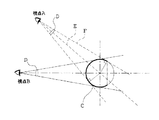
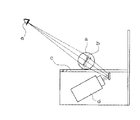
ここで、本発明の表示装置における画面を明るく均一にするための理論を図1と図2に示す球面状スクリーンに基づいて説明する。
図1は視点を変えて球面状スクリーンを観察したときの観察範囲を示し、図2は射出瞳(EP)との関係で拡散性を強くしなくても明るく見える範囲を示す。
Here, the theory for making the screen bright and uniform in the display device of the present invention will be described based on the spherical screen shown in FIGS.
FIG. 1 shows an observation range when a spherical screen is observed from different viewpoints, and FIG. 2 shows a range in which it looks bright without increasing diffusivity in relation to the exit pupil (EP).
図1に示すように、視点Aと視点Bでは画像表示エリアCの観察範囲D、すなわち球面に接する範囲が変化するが、いずれも球面に接する範囲であるので画像を観察できることになる。そして、図2に示すように、視点Aから観察した場合、球面の中心0を通る光軸をE、球面に接する光線をF、球面の屈折率をn、射出瞳位置をEPとすると、光線Fは外球面ではθc=sin-1(1/n)であり、内球面ではほぼθcで入射する。
入射瞳とこの点を結ぶ光路と、内球面のθcで入射する光線との内球面上で成す角度差が比較的小さいので、拡散が強くなくても明るく観察できる。
As shown in FIG. 1, the viewing range D of the image display area C, that is, the range in contact with the spherical surface changes between the viewpoint A and the viewpoint B, but since both are in contact with the spherical surface, the image can be observed. As shown in FIG. 2, when viewed from the viewpoint A, when the optical axis passing through the center 0 of the spherical surface is E, the light ray in contact with the spherical surface is F, the refractive index of the spherical surface is n, and the exit pupil position is EP, the light ray F is θc = sin −1 (1 / n) on the outer spherical surface, and is incident at approximately θc on the inner spherical surface.
Since the angle difference formed on the inner sphere between the optical path connecting the entrance pupil and this point and the ray incident at θc of the inner sphere is relatively small, bright observation is possible even if the diffusion is not strong.
したがって、射出瞳の位置は、+R/2>EP>−2R
の範囲がよい。
また、0>EP>−3/2R
であると、より効率的である。
Therefore, the position of the exit pupil is + R / 2>EP> -2R.
The range is good.
Also, 0>EP> -3 / 2R
If it is, it is more efficient.
また、本発明の表示装置においては好ましくは、投影光学系は、画角(2ω)は80度〜300度であり、プロジェクターの光路を拡大するアフォーカル光学系からなる。 In the display device of the present invention, it is preferable that the projection optical system has an angle of view (2ω) of 80 degrees to 300 degrees and an afocal optical system that expands the optical path of the projector.
画像は球体の内面に160度以上の範囲で投射すると、観察位置によらず画像が全方位から観察できる。 When the image is projected on the inner surface of the sphere in a range of 160 degrees or more, the image can be observed from all directions regardless of the observation position.
また、本発明の表示装置においては好ましくは、投影光学系は、画角(2ω)は80度〜300度であり、プロジェクターから投射された画像が結像レンズで一度中間像を結像したのち、投影レンズで拡大投影されるように構成されている。 In the display device of the present invention, it is preferable that the projection optical system has an angle of view (2ω) of 80 ° to 300 °, and the image projected from the projector forms an intermediate image once with an imaging lens. The projection lens is configured to be enlarged and projected.
画像は球体の内面に160度以上の範囲で投射すると、観察位置によらず画像が全方位から観察できる。 When the image is projected on the inner surface of the sphere in a range of 160 degrees or more, the image can be observed from all directions regardless of the observation position.
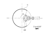
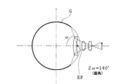
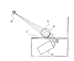
ここで、画像は球体の内面に160度以上の範囲で投射すると、観察位置によらず画像が全方位から観察できる理論を図3と図4に示す球面状スクリーンに基づいて説明する。
図3は画角(2ω)=220度、図4は画角(2ω)=140度の例を示す。
Here, the theory that the image can be observed from all directions regardless of the observation position when the image is projected onto the inner surface of the sphere in the range of 160 degrees or more will be described based on the spherical screen shown in FIGS.
FIG. 3 shows an example of the angle of view (2ω) = 220 degrees, and FIG. 4 shows an example of the angle of view (2ω) = 140 degrees.
図3に示すように、画角(2ω)=220度の場合は画像表示範囲はGとなり、EPを球心Oに近づけることにより、EPの後方となるスクリーンにまで画像を明るく均一に投影できる。また、図4に示すように、画角(2ω)=140度の場合は画像表示範囲はGとなり、EPを−Rに近づけることにより、スクリーンの広範囲に亘り画像を明るく均一に投影できる。 As shown in FIG. 3, when the angle of view (2ω) = 220 degrees, the image display range is G. By bringing the EP close to the sphere O, the image can be projected brightly and uniformly on the screen behind the EP. . Also, as shown in FIG. 4, when the angle of view (2ω) = 140 degrees, the image display range is G, and by making EP close to −R, an image can be projected brightly and uniformly over a wide range of the screen.
また、本発明の表示装置においては好ましくは、光路を折り曲げる光学系を備えている。 The display device of the present invention preferably includes an optical system that bends the optical path.
光路を折り曲げる光学系を備えることで小型化が可能となり、例えば、プロジェクターと球面の間に偏向プリズムを配置することで薄型化が可能となる。 By providing an optical system that bends the optical path, the size can be reduced. For example, by arranging a deflecting prism between the projector and the spherical surface, the thickness can be reduced.
また、本発明の表示装置においては好ましくは、2個の球面状スクリーンが軸まわりに回転可能に相対して配置され、一方の球面状スクリーンを回転すると、他方の球面状スクリーンも同様に回転するとともに、光路を折り曲げる光学系をプリズムで構成し、プリズムの光路が確保されるように、それぞれの球面状スクリーンの回転角が設定されている。 Further, in the display device of the present invention, preferably, two spherical screens are arranged so as to be rotatable around an axis, and when one spherical screen is rotated, the other spherical screen is similarly rotated. At the same time, the optical system for bending the optical path is constituted by a prism, and the rotation angle of each spherical screen is set so that the optical path of the prism is secured.
例えば、球面状スクリーンをドアノブとすると、ドアノブの回転角は光路を折り曲げる光学系を構成するプリズムの光路が確保される範囲に設定されているので、ドアノブをドアノブとしての機能を発揮させながら表示装置として利用することが可能となる。 For example, when a spherical screen is used as a door knob, the rotation angle of the door knob is set in a range that secures the optical path of the prism that constitutes the optical system that bends the optical path. It becomes possible to use as.
あるいは、本発明の表示装置は、2個の球面状スクリーンが軸まわりに回転可能に平板状部材を挟んで相対して連結部材により連結されて配置され、一方の球面状スクリーンを軸まわりに回転すると、他方の球面状スクリーンも同様に回転し、平板状部材内に1つ又は2つのプロジェクターが内蔵され、プロジェクターからの光束が光路偏向プリズムで前記球面状スクリーンに投射され、球面状スクリーンの回転角(φ)は、0度<φ<350度であり、プロジェクターからの光路をケラないように連結部材には切り欠き部が形成されていることを特徴としている。 Alternatively, in the display device of the present invention, two spherical screens are arranged to be connected to each other by a connecting member facing each other with a flat plate member interposed between them so that the spherical screen can be rotated about the axis. Then, the other spherical screen rotates in the same manner, and one or two projectors are built in the flat plate member, and the light flux from the projector is projected onto the spherical screen by the optical path deflecting prism, and the spherical screen rotates. The angle (φ) is 0 ° <φ <350 °, and the connecting member is formed with a notch so as not to vignett the optical path from the projector.
例えば平板状部材を扉パネルとし、球面状スクリーンをドアノブとして回転角を上記の範囲に設定することにより、ドアノブをドアノブとしての機能を発揮させながら表示装置として利用することが可能となる。 For example, by using a flat plate member as a door panel, a spherical screen as a door knob, and setting a rotation angle in the above range, the door knob can be used as a display device while exhibiting the function as a door knob.
あるいは、本発明の表示装置は、台座内にプロジェクターと偏向プリズムが設けられるとともに台座上に球面状スクリーンが保持部を介して設けられ、偏向プリズムでプロジェクターからの光路はほぼ直角に曲げられて球面状スクリーンの回転軸に一致させられ、球面状スクリーンの保持部は回転可能になっていて、球面状スクリーンの回転角の範囲では光路が保持部でケラれないように保持部に切り欠き部が設けられ、また、球面状スクリーンの回転角を検出し、回転角に応じて前記プロジェクターにより投影される画像が回転されるようになっていることを特徴としている。 Alternatively, in the display device of the present invention, the projector and the deflection prism are provided in the pedestal, and the spherical screen is provided on the pedestal via the holding unit, and the optical path from the projector is bent at a substantially right angle by the deflection prism. The holding portion of the spherical screen is rotatable so that the optical path does not shine at the holding portion within the rotation angle range of the spherical screen. The rotation angle of the spherical screen is detected, and the image projected by the projector is rotated according to the rotation angle.
プロジェクターと球面状スクリーンの間に偏向光路を配置することで薄型化する。また、球面状スクリーンは保持部で回転可能であって、回転角に応じてプロジェクターにより投影される画像が回転し、一定の回転角の範囲では保持部で光路がケラれないように保持部に切り欠き部が設けられているので、回転に応じて画像を変更したいような各種用途に適用可能である。 Thinning is achieved by arranging a deflection optical path between the projector and the spherical screen. In addition, the spherical screen can be rotated by the holding unit, and the image projected by the projector rotates according to the rotation angle, so that the optical path is not vignetted by the holding unit within a certain rotation angle range. Since the notch is provided, the present invention can be applied to various uses in which an image is desired to be changed according to rotation.
また、本発明の表示装置においては好ましくは、プロジェクターには、任意箇所に設置された撮像手段により取得された画像が入力される。 In the display device of the present invention, it is preferable that an image acquired by an imaging unit installed at an arbitrary location is input to the projector.
プロジェクターから投影される画像についての制限はなく、例えばメモリーに記憶した画像やコンピュータ画像を表示しても良いが、別途撮像手段を設けておきこの画像を表示するようにしてもよい。例えば、スクリーンをドアノブとし、扉パネルに撮像手段を設ければ、ドア付近の様子をスクリーンで観察することが出来る。 There is no restriction on the image projected from the projector. For example, an image stored in a memory or a computer image may be displayed. Alternatively, an image pickup unit may be provided to display this image. For example, if the screen is a door knob and an imaging means is provided on the door panel, the state near the door can be observed on the screen.
さらに、本発明の表示装置は、内視鏡の操作部又は本体部に取り付け可能な請求項10に記載した表示装置であって、球面状スクリーンを回転させると、その回転角を検出して回転角に応じて内視鏡の撮像手段が回動させられることを特徴としている。 Furthermore, the display device of the present invention is the display device according to claim 10, which can be attached to an operation part or a main body part of an endoscope. When the spherical screen is rotated, the rotation angle is detected and rotated. The imaging means of the endoscope is rotated according to the angle.
球面状スクリーンを回転させると、それに応じて内視鏡の撮像手段が回動するので、内視鏡の撮像方向をスクリーンで観察して実感できる。特に、タンクのような半球状のものの観察に適する。 When the spherical screen is rotated, the imaging means of the endoscope rotates accordingly, so that the imaging direction of the endoscope can be observed and felt on the screen. In particular, it is suitable for observation of a hemispherical object such as a tank.
<実施例1>
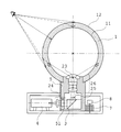
次に、本発明の表示装置の基本的構成を図5に基づいて説明する。
本発明の表示装置は、中空状の球面状スクリーン1と、球面状スクリーン1の内側となる球心側に配置された放射状の光路を有する投影光学系2と、偏向プリズム3と、プロジェクター4とから構成されている。
<Example 1>
Next, a basic configuration of the display device of the present invention will be described with reference to FIG.
The display device of the present invention includes a hollow
球面状スクリーン1はガラスやアクリル樹脂などの合成樹脂で形成された透明体であり、内球面11側は表面が拡散面でありスクリーンとして機能し、外球面12側はつるつるの研磨面となっている。なお、球面状スクリーン1の大きさは適宜選択でき、また球面状スクリーン1の肉厚も適宜選択可能である。さらに、球面状スクリーン1は拡散面となる内球面11の内側にさらに透明部があってもよい。
The
投影光学系2はアフォーカル光学系であり、前方から凹レンズ群21と凸レンズ群22とから構成されている。また、画角(2ω)は80度〜300度とする。そして、球面状スクリーン1の球心点を0(ゼロ)とし、内球面11の位置をRとすると、射出瞳(EP)位置23が、+R/2>EP>−2Rの範囲となるように設定されている。また、投影光学系2は球面状スクリーン1を保持する球面保持部5内に収納され、球体保持部5は平板状部材6の上に設けられている。
The projection
プロジェクター4と偏向プリズム3は台座となる平板状部材6の中に収納されており、プロジェクター4から投射された画像は偏向プリズム3で光路が折り曲げられ、平板状部材6の上に設けられている球体保持部5に収納されている投影光学系2に投射されるようになっている。
The
上記のように構成されているので、プロジェクター4から画角wで画像が投影されると、偏向プリズム3でほぼ直角に曲げられる。そして、投影光学系2はアフォーカル光学系であるので画角wは、β×wに拡大される。そして、射出瞳位置23から放射状に画角β×w(2ω)で、半径Rの内球面11に投影される。すると、内球面1の散乱面で光が拡散されることとなり、球面状スクリーン1の透明体を透過して外球面12の全方位から画像が観察されることとなる。
Since it is configured as described above, when an image is projected from the
本実施例においては、プロジェクター4が平板状部材6に配置されているので装置全体として薄型である。そして、射出瞳位置5から全方位に画像が投影されるので球面状スクリーン1全体がスクリーンとして機能し、球全体に画像が表示される。さらに、射出瞳の位置と内面球の球心が近いので、どの方位から観察しても明るい画像が見え、また、画像は歪みが少なく観察出来る。
In the present embodiment, since the
なお、本実施例の変形例として、偏向プリズム3を設けず、光路が途中で折り曲げられないようにしてもよい。このような構成にすると、プロジェクター4から投射された画像は途中で光路が折り曲げられることなく平板状部材6の上に設けられている球体保持部5に収納されている投影光学系2に投射されることとなる。用途によっては、平板状部材6を図5に対し縦型にでき、都合がよい場合もある。
As a modification of the present embodiment, the deflecting
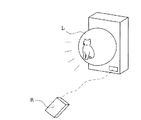
本実施例は例えば、図14に示す占い球や、図17に示す壁面埋込型シグナルランプに適用可能である。図17に示す壁面埋込型シグナルランプLはリモコンRの操作により任意の色や画像表示を伴って発光するシグナルランプである。単なる光の変化ではなく、具体的な情報を表示可能である。 The present embodiment can be applied to, for example, a fortune-telling ball shown in FIG. 14 and a wall-embedded signal lamp shown in FIG. A wall-embedded signal lamp L shown in FIG. 17 is a signal lamp that emits light with an arbitrary color or image display by the operation of the remote controller R. Specific information can be displayed, not just light changes.
<実施例2>
次に、本発明の表示装置の他例を図6に基づいて説明する。
本発明の表示装置は、中空状の球面状スクリーン1と、球面状スクリーン1の内側となる球心側に配置された放射状の光路を有する投影光学系2と、偏向プリズム3と、プロジェクター4とから構成されている。
<Example 2>
Next, another example of the display device of the present invention will be described with reference to FIG.
The display device of the present invention includes a hollow
球面状スクリーン1はガラスやアクリル樹脂などの合成樹脂で形成された透明体であり、内球面11側は表面が拡散面でありスクリーンとして機能し、外球面12側はつるつるの研磨面となっている。なお、球面状スクリーン1の大きさは適宜選択でき、また球面状スクリーン1の肉厚も適宜選択可能である。さらに、球面状スクリーン1は拡散面となる内球面11の内側にさらに透明部があってもよい。これらは、上記実施例1と同様である。
The
投影光学系2は、プロジェクター4から投射された画像は一度結像レンズ24で中間像25を結像し、偏向プリズム3で光路が折り曲げられた後、投影レンズ26で拡大投影されるようになっている。また、画角(2ω)は80度〜300度とする。そして、球面状スクリーン1の球心点を0(ゼロ)とし、内球面11の位置をRとすると、射出瞳(EP)位置23が、+R/2>EP>−2Rの範囲となるように設定されている。また、投影光学系2のうち投影レンズ26は球面状スクリーン1を保持する球面保持部5内に収納されている。
In the projection
プロジェクター4と偏向プリズム3と投影光学系2の結像レンズ24は台座となる平板状部材6の中に収納されており、プロジェクター4から投射された画像は結像レンズ24により中間像25を一度結像した後、偏向プリズム3で光路が折り曲げられ、平板状部材6の上に設けられている球体保持部5に収納されている投影光学系2の投影レンズ26に投射されるようになっている。
The
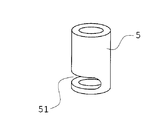
そして、図示した本実施例では球体保持部5は平板状部材6に対し、投影レンズ25の光軸を中心として回動可能に設けられている。また、球面状スクリーン1も球体保持部5と一体的に回転し、球体保持部5のプロジェクター4に面する側には図7に示すような切り欠き部51が形成されている。切り欠き部51は球体保持部5が回動した場合に、光路が球体保持部5でケラれないようにするためである。また、球体保持部5の切り欠き部51と反対側は歯車7と螺合するように形成してあり、球体保持部5が回転すると歯車7が回転し、回転角が角度検出センサー8で検出されるようになっている。なお、球体保持部5が回動しない場合はこのような仕組みは不要である。
In the illustrated embodiment, the spherical
上記のように構成されているので、プロジェクター4から画角wで画像が投射されると結像レンズ24により中間像25が結像される。そして、偏向プリズム3でほぼ直角に光路を曲げられる。中間像25は投影レンズ26で拡大されて画角θで半径Rの内面球11に投影される。すると、内球面11の散乱面で光が拡散されることとなり、球面状スクリーン1の透明体を透過して外球面12の全方位から画像が観察されることとなる。
Since it is configured as described above, an
また、球面保持部5と投影レンズ26と球面状スクリーン1は一体となって投影レンズ26の光軸まわりに回転し、球体保持部5が回転するとこれと螺合している歯車7が回され、角度検出センサー8で回転角が検出される。なお、球体保持部の5の回動範囲は、プロジェクター4と結像レンズ24の光路がケラれないように設定された球体保持部5切り込み部51の範囲内、例えば±175度以内で回転するようにする。
Further, the
そして、角度検出センサー8で検出される回転角をフィードバックしてプロジェクター4から投射される画像を変化させるようにするようにしてもよい。また、球面状スクリーン1に視認可能な指標や図柄を表示しておき、球面状スクリーン1の回転角に応じて変化して表示される画像とこの指標の一致を認識し、これをフィードバックして更に投射される画像に反映させるようにしてもよい。
Then, the rotation angle detected by the
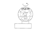
本実施例は、例えば図15に示すような星座占い玉に適用可能である。球面状スクリーン1の外球面12表面に生まれ月が書いてある占い球を回転させ、プロジェクター4から占いに関する画像を投影するようにする。
また、球面状スクリーン1の外球面12表面に緯度経度が書いてある天球儀や地球儀や、概要が書いてあるゲーム用の表示球などに応用可能である。
This embodiment can be applied to, for example, a constellation horoscope ball as shown in FIG. A fortune telling sphere on which the moon is written on the surface of the outer
Further, the present invention can be applied to a celestial sphere or globe in which latitude and longitude are written on the surface of the outer
<実施例3>
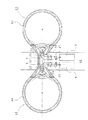
次に、本発明の表示装置の他例を図8に基づいて説明する。本実施例は基本的には上記した実施例2の表示装置を対向させて2個設けたものであり、例えばドアノブ等に適用可能なものである。本実施例では球面状スクリーン1をドアノブ13の把持部14とし、平板状部材6を扉パネル61とする。
<Example 3>
Next, another example of the display device of the present invention will be described with reference to FIG. In the present embodiment, two display devices according to the second embodiment described above are basically provided facing each other, and can be applied to, for example, a door knob. In this embodiment, the
扉パネル61を挟んでドアノブ13が、扉パネル61を貫通していて両側が球体保持部5となっている球体連結部材52に対向させて設けられている。球体連結部材52は扉パネル61に対して回動可能となっており、また一方のドアノブ13を回転させると他方のドアノブ13も同時に回転するようになっている。また、球体連結部材52には切り欠き部51が形成されており、球体連結部材52が回動した場合に、光路が球体連結部材52でケラれないようになっている。
The
扉パネル61内にはプロジェクター4が2個併設され、それぞれのプロジェクター4から投射された画像はクサビプリズム27を透過し、一度それぞれの結像レンズ24により中間像25を結像し、それぞれの偏向プリズム3で光路が折り曲げられた後、それぞれの投影レンズ26によりそれぞれのドアノブ13の把持部14に拡大投影されるようになっている。
Two
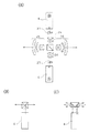
なお、扉パネル61内にプロジェクター4と偏向プリズム3と投影光学系2を設けるに際しては、図9に示すように設けてもよい。図9(A)はプロジェクター4を扉パネル61内に上下に配置し、偏向プリズム3を2個組み合わせるように配置したものである。図9(B)はプロジェクター4を1個としたものであり、1個のプロジェクター4から投射された画像を2個の偏向プリズム3で左右の把持部14へ同時に投影するようにしたものである。この場合は左右同じ画像が投影される。図9(C)はプロジェクター4を1個としたものであり、1個のプロジェクター4から投射された画像を1個の偏向プリズム3で左右の把持部14へ同時に投影するようにしたものである。この場合、投影画像は、投影像を分割して左右異なる画像を投影できる。いずれの場合もプロジェクター1個分の厚さでよいので、扉パネル内にプロジェクターを2個併設する場合と比べ、薄い扉パネル61でも設置可能である。
When the
本実施例においては、ドアノブ13の把持部14に画像が表示される。そして、従来のドアノブを本発明のドアノブ表示装置と交換することにより、プロジェクターがドア内に収納出来るので大規模な工事を行わなくてもドアノブ13の把持部14に画像を表示することが可能となる。なお、基本的にはドアノブ13を回しても把持部14に表示される画像は回転させない。また球面連結部材52には切り欠き部51が形成してあるのでドアノブ13を回しても把持部14に表示される画像がケラれない。そして、左右のドアノブ13は球面連結部材52により連結されているので通常のドアノブのように使用出来る。なお、メモリーに記録した画像、コンピュータ画像、カメラで取り込んだ画像などを表示可能である。
In this embodiment, an image is displayed on the
本実施例は例えば、図16に示すドアノブ表示装置に適用可能である。ドアノブ13の把持部14を球面状スクリーン1とし、表示面とする。
なお、図示した本実施例ではドアノブ13の回転角度を検出する角度検出センサー8は設けていないが、角度検出センサーを設けることも可能である。また、扉パネル61のドアノブ13の近傍などにCCDカメラなどの撮像手段を設け、その画像をドアノブ13の把持部14に投影することも可能である。
This embodiment is applicable to the doorknob display device shown in FIG. The
In the illustrated embodiment, the
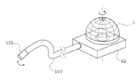
<実施例4>
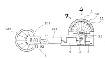
次に、本発明の表示装置の他例を図10,図11に基づいて説明する。本実施例は、タンク内の観察に使用するための内視鏡に使用可能なものである。基本的には実施例2の表示装置を内視鏡本体62とし、これに撮像手段9を設けた挿入部100を取り付けたものであり、球面状スクリーン1を回転させるとこの回転角度を角度センサー8が検出し、撮像手段9が回転するようになっている。
<Example 4>
Next, another example of the display device of the present invention will be described with reference to FIGS. This embodiment can be used for an endoscope for use in observation in a tank. Basically, the display device of the second embodiment is an endoscope
内視鏡本体62となる表示装置部分は例えば実施例2に示したような機構により球面状スクリーン1を回動可能にするとともに、この回転角度が角度センサー8により検出されるようにする。また、球面状スクリーン1の回転により光路がケラれないようにするため、球面状スクリーン1の回動範囲を球体保持部5の切り欠き部51の大きさに合わせる。
The display device portion which becomes the endoscope
フレキシブルな挿入部100の先端には先端部101が着脱可能に配されており、先端部101には撮像手段9を構成する対物レンズ91とCCD92が設けられている。そして、先端部101は球面状スクリーン1の回転角度に対応させて撮影アングルが変化するように回動するようになっており、CCD92が回転することにより球面状スクリーン1には球面状スクリーン1の回転角度に対応させた画像が投影されることとなる。
A
このような構成とすることにより、球面状スクリーン1を回転すると角度センサー8が回転角度を検出し、それに応じて先端部101のアングルが同期するように変更され、先端部101の撮影方向と観察状態を球面状スクリーン1で実感出来る。また、対物レンズ91の負ディストーションと投影レンズ26の正ディストーションが相殺されることによりディストーションが補正され、球面状スクリーン1の画像は、実際に近い表示となり、先端光学系の歪みが補正されるので見やすい。特に、タンクのような球体を観察する場合、被検査物102の球体の状況が、表示(観察側)の球体で見やすく再現される。
With this configuration, when the
本実施例は例えば、タンク内の検査を行うための内視鏡として適用可能である。また、球面状スクリーン1の形状は被検査物の形状に合わし、例えば半球状であってもよく、あるいはほぼ球体に近い形状であってもよい。
This embodiment can be applied as, for example, an endoscope for inspecting a tank. Further, the shape of the
<実施例5>
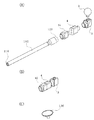
次に、本発明の表示装置を内視鏡に使用した他例を図12に基づいて説明する。本実施例は、挿入部100がステンレスチューブ製の硬性鏡となっており、挿入部100は先端側にはLED110が設けられ、CCD92接続側には接眼レンズ120が設けられている。挿入部100とCCD92とプロジェクター4と偏向プリズム3はそれぞれ着脱可能になっている。そして、図12(B)に示すように、CCD92、プロジェクター4、偏向プリズム3が連結され、CCD92とプロジェクター4は固定され、プロジェクター4と偏向プリズム3とは回動可能に連結される図示しない回転部を有しており、プリズム3に対しプロジェクター4が回動可能となっているとともに、プロジェクター4が回動するとCCD92も一体的に回動するようになっている。
<Example 5>
Next, another example in which the display device of the present invention is used in an endoscope will be described with reference to FIG. In this embodiment, the
偏向プリズム3には球面状スクリーン1が回動可能に配されており、プロジェクター4から投射された画像が投影光学系(図示せず)により球面状スクリーン1に投射されるようになっている。また、球面状スクリーン1を回転させると角度センサー(図示せず)がその回転角度を検出し、プロジェクター4を球面状スクリーン1の回転角度に対応させて撮影アングルが変化するように回動する。プロジェクター4が回転することによりCCD92も同時に回転し、球面状スクリーン1にはその回転角度に対応させた画像が投影されることとなる。
A
また、球面状スクリーン1に代え、被検査物によってはスクリーンを図12(C)に示すような円形の平板スクリーン130としてもよい。平板スクリーン130とする場合も、表示部は透明体で内側は拡散面で外側は鏡面となるように形成する。そして、平板スクリーン130と球面状スクリーン1を交換可能としてもよい。
Further, instead of the
このような構成とすることにより、球面状スクリーン1や平板スクリーン130を回動させるとプロジェクター4が回転することにより、球面状スクリーン1や平板スクリーン130にはその回転角度に対応させた画像が投影されることとなる。なお、プロジェクター4は固定とし、CCD92のみが回転するようにしてもよい。
With such a configuration, when the
<実施例6>
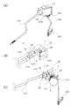
次に、本発明の表示装置を内視鏡に使用した他例を図13に基づいて説明する。
本実施例は、実施例5の挿入部100をフレキシブルな蛇管とし、表示部を矩形の平板スクリーン130’や球面状スクリーン1としたものである。
挿入部100はプロジェクターユニット40と一体化されており、プロジェクターユニット40は図13(B)に示すように、接眼レンズ120とCCD92とプロジェクター4と結像レンズ24から構成されている。また、プリズムユニット30は偏向プリズム3と投影レンズ26から構成されていて、プリズムユニット30に対しプロジェクターユニット40は矢印A方向に回転可能となっている。
<Example 6>
Next, another example in which the display device of the present invention is used in an endoscope will be described with reference to FIG.
In the present embodiment, the
The
挿入部100内にはイメージファイバ150が設けられ、接眼レンズ120を経てCCD92で撮像されるようになっている。
そして、プロジェクター4から投射された画像は実施例2と同様に一度結像レンズ24で中間像25を結像し、偏向プリズム3で光路が折り曲げられた後、投影レンズ26で平板スクリーン130’や球面状スクリーン1に拡大投影されるようになっている。
An
The image projected from the
また、図13(A)、(B)の変形として、球面状スクリーンの場合を示す。
球面状スクリーン1の根元には、図13(C)に示すようにスクリーン固定部140が設けられ、球面状スクリーン1がプリズムユニット30に対して回転可能に取り付けられている。また、球面状スクリーンを取り付けるためのスクリーン固定部140が設けられ、球面状スクリーン1が机等に固定され、プリズムユニット30は球面状スクリーン1に対して矢印B方向に回転可能に取り付けられている。
そして、スクリーン固定部140には、アーム141及び表示装置固定部142が設けられており、表示装置固定部142により適当な場所に固定することが可能となっている。
なお、図13(A)に示す平板スクリーン130’の場合も、平板スクリーン130’を取り付けるためのスクリーン固定部140が設けられ、平板スクリーン130’に対してプリズムユニットを回動可能としても良い。
Further, as a modification of FIGS. 13A and 13B, a case of a spherical screen is shown.
As shown in FIG. 13C, a
The
In the case of the
この状態で、挿入部100を被検体に挿入して検査を行う場合、必要に応じて挿入部100をねじることもある。
プリズムユニット30に対しプロジェクターユニット40は矢印A方向に回転可能となっているので、挿入部100をねじることにより、挿入部100とプロジェクターユニット40がレンズユニット30に対して矢印A方向に回転されることになる。
また、球面状スクリーン1や平板スクリーン130’がプリズムユニット30に対して矢印B方向に回転可能に取り付けられているので、挿入部100を上下させることにより、挿入部100とプロジェクターユニット40とプリズムユニット30の部分が一体となって矢印B方向に回転されることになる。
A方向とB方向に回転可能とすることにより、挿入部100を上下動又は回転させても、挿入部100の根元に無理な力がかからないというメリットがある。
In this state, when the
Since the
Further, since the
By enabling rotation in the A direction and the B direction, there is an advantage that an excessive force is not applied to the base of the
さらに、実施例5と同様に球面状スクリーン1や平板スクリーン130’を回動させるとプロジェクター4が回転し、球面状スクリーン1や平板スクリーン130’にはその回転角度に対応した画像が投影されるように構成されており、球面状スクリーン1や平板スクリーン130’を回動させるとプロジェクター4が回転することにより、球面状スクリーン1や平板スクリーン130’にはその回転角度に対応させた画像が投影されることとなる
Further, as in the fifth embodiment, when the
なお、内視鏡は、先端にCCDを設けたビデオスコープの場合でもよい。この場合、接眼レンズ、CCDは、手元側には設けず、先端のCCDの信号をプロジェクターに入れる構造である。 The endoscope may be a video scope provided with a CCD at the tip. In this case, the eyepiece lens and the CCD are not provided on the hand side, and the structure is such that the CCD signal at the tip is input to the projector.
本発明の適用範囲は上記実施例に限定されるものではなく、スクリーンの形状や大きさや、球面状スクリーンの大きさにも制限はないので、娯楽用から実用的な用途まで各種のものに使用可能である。 The scope of application of the present invention is not limited to the above embodiment, and there is no limitation on the shape and size of the screen and the size of the spherical screen, so it can be used for various purposes from entertainment to practical use. Is possible.
1 球面状スクリーン
11 内球面
12 外球面
13 ドアノブ
14 把持部
2 投影光学系
21 凹レンズ群
22 凸レンズ群
23 射出瞳位置
24 結像レンズ
25 中間像
26 投影レンズ
27 クサビプリズム
3 偏向プリズム
30 プリズムユニット
4 プロジェクター
40 プロジェクターユニット
5 球体保持部
51 切り欠き部
52 球面連結部材
6 平板状部材
61 扉パネル
62 内視鏡本体
7 歯車
8 角度検出センサー
9 撮像手段
91 対物レンズ
92 CCD
100 挿入部
101 先端部
102 被検査物
110 LED
120 接眼レンズ
130,130’ 平板スクリーン
140 スクリーン固定部
141 アーム
142 表示装置固定部
150 イメージファイバ
DESCRIPTION OF
100
120
Claims (15)
スクリーンの内側に配置された投影光学系と、
光路を折り曲げる光学系と、
プロジェクターと、からなり、
スクリーンは外側表面がつるつる面で内面が拡散面からなる透明部材であることを特徴とする表示装置。 Screen,
A projection optical system arranged inside the screen;
An optical system that bends the optical path;
A projector,
A display device, wherein the screen is a transparent member whose outer surface is a smooth surface and whose inner surface is a diffusion surface.
平らな板状であることを特徴とする請求項1に記載の表示装置。 The screen is
The display device according to claim 1, wherein the display device has a flat plate shape.
任意の曲面部を有する形状であることを特徴とする請求項1に記載の表示装置。 The screen is
The display device according to claim 1, wherein the display device has an arbitrary curved surface portion.
前記スクリーンを回転させると、その回転角を検出して回転角に応じて内視鏡の撮像手段が回動させられることを特徴とする表示装置。 The display device according to any one of claims 1 to 3, which can be attached to an operation unit or a main body of an endoscope,
When the screen is rotated, the rotation angle is detected, and the imaging means of the endoscope is rotated according to the rotation angle.
スクリーンの内側となる球心側に配置された放射状の光路を有する投影光学系と、
プロジェクターと、からなることを特徴とする表示装置。 The screen is a spherical screen,
A projection optical system having a radial optical path disposed on the spherical center side which is the inside of the screen;
And a projector.
外側表面がつるつる面でほぼ同心の内面球面が拡散面の透明部材からなるほぼ球面の中空構造のスクリーンであることを特徴とする請求項5に記載の表示装置。 The spherical screen is
6. The display device according to claim 5, wherein the outer surface is a smooth surface and the substantially concentric inner spherical surface is a substantially spherical hollow screen made of a transparent member having a diffusing surface.
球心点を0(ゼロ)とし、前記内面球面の位置をRとすると、
+R/2>EP>−2R
であることを特徴とする請求項6に記載の表示装置。 The exit pupil (EP) position of an optical system having a radial optical path is:
When the spherical center point is 0 (zero) and the position of the inner spherical surface is R,
+ R / 2>EP> -2R
The display device according to claim 6, wherein the display device is a display device.
画角(2ω)は80度〜300度であり、
前記プロジェクターの光路を拡大するアフォーカル光学系からなることを特徴とする請求項7に記載の表示装置。 The projection optical system is
The angle of view (2ω) is 80 to 300 degrees,
The display device according to claim 7, comprising an afocal optical system that expands an optical path of the projector.
画角(2ω)は80度〜300度であり、
前記プロジェクターから投射された画像が結像レンズで一度中間像を結像したのち、
投影レンズで拡大投影されるように構成されていることを特徴とする請求項7に記載の表示装置。 The projection optical system is
The angle of view (2ω) is 80 to 300 degrees,
After the image projected from the projector forms an intermediate image once with the imaging lens,
The display device according to claim 7, wherein the display device is configured to be enlarged and projected by a projection lens.
前記光路を折り曲げる光学系をプリズムで構成し、該プリズムの光路が確保されるように、それぞれの前記球面状スクリーンの回転角が設定されていることを特徴とする請求項8に記載の表示装置。 The two spherical screens are rotatably arranged around an axis, and when one of the spherical screens is rotated, the other spherical screen is similarly rotated,
9. The display device according to claim 8, wherein an optical system for bending the optical path is configured by a prism, and the rotation angle of each spherical screen is set so that the optical path of the prism is secured. .
前記平板状部材内に1つ又は2つのプロジェクターが内蔵され、
前記プロジェクターからの光束が光路偏向プリズムで前記球面状スクリーンに投射され、
前記球面状スクリーンの回転角(φ)は、0度<φ<350度であり、
前記プロジェクターからの光路をケラないように前記連結部材には切り欠き部が形成されていることを特徴とする表示装置。 Two spherical screens are arranged to be connected to each other by connecting members so as to be rotatable around an axis with a flat plate-like member interposed therebetween. When one spherical screen is rotated around the axis, the other spherical screen is also the same Rotate to
One or two projectors are built in the flat plate member,
The light beam from the projector is projected onto the spherical screen by an optical path deflecting prism,
The rotation angle (φ) of the spherical screen is 0 degree <φ <350 degree,
The display device is characterized in that a cutout portion is formed in the connecting member so as not to vignett the optical path from the projector.
前記偏向プリズムで前記プロジェクターからの光路はほぼ直角に曲げられて前記球面状スクリーンの回転軸に一致させられ、
前記球面状スクリーンの前記保持部は回転可能になっていて、前記球面状スクリーンの回転角の範囲では光路が前記保持部でケラれないように前記保持部に切り欠き部が設けられ、
また、前記球面状スクリーンの回転角を検出し、回転角に応じて前記プロジェクターにより投影される画像が回転されるようになっていることを特徴とする表示装置。 A projector and a deflecting prism are provided in the pedestal, and a spherical screen is provided on the pedestal via a holding unit,
The optical path from the projector is bent at a substantially right angle by the deflecting prism so as to coincide with the rotational axis of the spherical screen,
The holding portion of the spherical screen is rotatable, and a notch portion is provided in the holding portion so that an optical path is not vignetted by the holding portion in the range of the rotation angle of the spherical screen,
The display device is characterized in that a rotation angle of the spherical screen is detected, and an image projected by the projector is rotated according to the rotation angle.
任意箇所に設置された撮像手段により取得された画像が入力されるようにしたことを特徴とする請求項1〜13の何れかに記載した表示装置。 The projector includes
The display device according to claim 1, wherein an image acquired by an imaging unit installed at an arbitrary location is input.
前記球面状スクリーンを回転させると、その回転角を検出して回転角に応じて内視鏡の撮像手段が回動させられることを特徴とする表示装置。 The display device according to claim 10, attachable to an operation part or a main body part of an endoscope,
When the spherical screen is rotated, the rotation angle is detected, and the imaging means of the endoscope is rotated according to the rotation angle.
Priority Applications (1)
| Application Number | Priority Date | Filing Date | Title |
|---|---|---|---|
| JP2010110448A JP2011237682A (en) | 2010-05-12 | 2010-05-12 | Display device |
Applications Claiming Priority (1)
| Application Number | Priority Date | Filing Date | Title |
|---|---|---|---|
| JP2010110448A JP2011237682A (en) | 2010-05-12 | 2010-05-12 | Display device |
Publications (2)
| Publication Number | Publication Date |
|---|---|
| JP2011237682A true JP2011237682A (en) | 2011-11-24 |
| JP2011237682A5 JP2011237682A5 (en) | 2013-06-27 |
Family
ID=45325710
Family Applications (1)
| Application Number | Title | Priority Date | Filing Date |
|---|---|---|---|
| JP2010110448A Pending JP2011237682A (en) | 2010-05-12 | 2010-05-12 | Display device |
Country Status (1)
| Country | Link |
|---|---|
| JP (1) | JP2011237682A (en) |
Citations (4)
| Publication number | Priority date | Publication date | Assignee | Title |
|---|---|---|---|---|
| JPH0822077A (en) * | 1994-05-02 | 1996-01-23 | Dainippon Printing Co Ltd | Transmission type screen |
| JPH0943732A (en) * | 1995-08-03 | 1997-02-14 | Mitsubishi Rayon Co Ltd | Rear surface transmission type screen |
| JP2003302701A (en) * | 2002-04-11 | 2003-10-24 | Plannings Naniwa:Kk | Projector |
| JP2006511848A (en) * | 2002-12-20 | 2006-04-06 | グローバル イマジネーション | Projection type display device having a three-dimensional convex display surface |
-
2010
- 2010-05-12 JP JP2010110448A patent/JP2011237682A/en active Pending
Patent Citations (4)
| Publication number | Priority date | Publication date | Assignee | Title |
|---|---|---|---|---|
| JPH0822077A (en) * | 1994-05-02 | 1996-01-23 | Dainippon Printing Co Ltd | Transmission type screen |
| JPH0943732A (en) * | 1995-08-03 | 1997-02-14 | Mitsubishi Rayon Co Ltd | Rear surface transmission type screen |
| JP2003302701A (en) * | 2002-04-11 | 2003-10-24 | Plannings Naniwa:Kk | Projector |
| JP2006511848A (en) * | 2002-12-20 | 2006-04-06 | グローバル イマジネーション | Projection type display device having a three-dimensional convex display surface |
Similar Documents
| Publication | Publication Date | Title |
|---|---|---|
| JP4147054B2 (en) | Stereoscopic observation device | |
| US7088516B2 (en) | Wide field of view head mounted display device | |
| US5384654A (en) | Image observation device | |
| US7738179B2 (en) | Image display device using P-polarized light and S-polarized light | |
| US7184212B2 (en) | Observation apparatus | |
| US20080252970A1 (en) | Stereoscopic display unit and stereoscopic vision observation device | |
| JP2007020866A (en) | Rigid endoscope | |
| JP2003207743A (en) | Stereoscopic observation apparatus | |
| TW200522911A (en) | Endoscopic instrument and imaging method using same | |
| JP4225816B2 (en) | Projection optical device | |
| JP2004177920A (en) | Projection observation device | |
| JP2008309859A (en) | Optical system and endoscope using the same | |
| US7130119B2 (en) | Three-dimensional observation apparatus and three-dimensional observation system | |
| US6081372A (en) | Stereoscopic microscope with convergent optics provided with a slot lamp for video recording | |
| JP2006039565A (en) | Optical microscope condenser for bright and/or dark field illumination | |
| JP2005062314A (en) | Retroreflective optical screen and observation device using the same | |
| WO2011141925A1 (en) | Ear nose throat multiscope and recorder | |
| JP6467585B2 (en) | Aerial and virtual image display device | |
| JP2011237682A (en) | Display device | |
| JP2006011145A (en) | Binocular microscope apparatus | |
| JP4166479B2 (en) | Display optical system and portable terminal device using display optical system | |
| JP2008064950A (en) | Visual display device | |
| JPH0876030A (en) | Solid endoscope having curved peeping direction | |
| JP2006053321A (en) | Projection observation device | |
| JP4300601B2 (en) | Binocular microscope and imaging method using binocular microscope |
Legal Events
| Date | Code | Title | Description |
|---|---|---|---|
| A521 | Request for written amendment filed |
Free format text: JAPANESE INTERMEDIATE CODE: A523 Effective date: 20130510 |
|
| A621 | Written request for application examination |
Free format text: JAPANESE INTERMEDIATE CODE: A621 Effective date: 20130510 |
|
| A977 | Report on retrieval |
Free format text: JAPANESE INTERMEDIATE CODE: A971007 Effective date: 20131211 |
|
| A131 | Notification of reasons for refusal |
Free format text: JAPANESE INTERMEDIATE CODE: A131 Effective date: 20131217 |
|
| A02 | Decision of refusal |
Free format text: JAPANESE INTERMEDIATE CODE: A02 Effective date: 20140507 |