JP2011237365A - Abnormality detection system - Google Patents
Abnormality detection system Download PDFInfo
- Publication number
- JP2011237365A JP2011237365A JP2010110941A JP2010110941A JP2011237365A JP 2011237365 A JP2011237365 A JP 2011237365A JP 2010110941 A JP2010110941 A JP 2010110941A JP 2010110941 A JP2010110941 A JP 2010110941A JP 2011237365 A JP2011237365 A JP 2011237365A
- Authority
- JP
- Japan
- Prior art keywords
- pipe
- odor
- exhaust
- abnormality detection
- detector
- Prior art date
- Legal status (The legal status is an assumption and is not a legal conclusion. Google has not performed a legal analysis and makes no representation as to the accuracy of the status listed.)
- Pending
Links
Images
Classifications
-
- Y—GENERAL TAGGING OF NEW TECHNOLOGICAL DEVELOPMENTS; GENERAL TAGGING OF CROSS-SECTIONAL TECHNOLOGIES SPANNING OVER SEVERAL SECTIONS OF THE IPC; TECHNICAL SUBJECTS COVERED BY FORMER USPC CROSS-REFERENCE ART COLLECTIONS [XRACs] AND DIGESTS
- Y02—TECHNOLOGIES OR APPLICATIONS FOR MITIGATION OR ADAPTATION AGAINST CLIMATE CHANGE
- Y02E—REDUCTION OF GREENHOUSE GAS [GHG] EMISSIONS, RELATED TO ENERGY GENERATION, TRANSMISSION OR DISTRIBUTION
- Y02E30/00—Energy generation of nuclear origin
- Y02E30/30—Nuclear fission reactors
Abstract
Description
本発明は、異常検出システムに関する。 The present invention relates to an abnormality detection system.
原子炉施設や放射性同位体元素を取り扱う放射線取扱施設などには、これらに設けられている各区画の内部の一部の空気をサンプリングし、その空気中の放射性核種の濃度を連続して測定するダスト放射線モニタ検出器が設置される。放射線取扱施設の各区画の内部にある全ての空気(サンプリングされた空気を含む)は、排気筒モニタによる測定監視されたのち、放射線取扱施設の排気口から放射線取扱施設の外部に排出される(例えば、非特許文献1参照)。 For reactor facilities and radiation handling facilities that handle radioisotopes, a part of the air inside each section is sampled and the concentration of radionuclides in the air is measured continuously. A dust radiation monitor detector is installed. All air (including sampled air) inside each section of the radiation handling facility is measured and monitored by an exhaust stack monitor and then discharged from the radiation handling facility to the outside of the radiation handling facility ( For example, refer nonpatent literature 1).
また、放射線取扱施設の各区画には、通常の施設に設けられる煙検知器や熱感知器も設けられている。 In addition, each section of the radiation handling facility is provided with a smoke detector and a heat detector provided in a normal facility.
ところで、原子力事業者は、原子力災害の発生の防止に関し万全の措置を、誠意をもって必要な措置を講ずる責務を有する(例えば、原子力災害対策特別措置法3条など)。 By the way, the nuclear power company is responsible for taking all possible measures for preventing the occurrence of a nuclear disaster and taking necessary measures in good faith (for example, Article 3 of the Special Measures Law for Nuclear Disaster Countermeasures).
また、災害発生を早期に検知するシステムとして、匂い感度が高い匂い検知器の利用が注目されている(例えば、非特許文献2、3、4、5など)。
In addition, the use of an odor detector with high odor sensitivity has attracted attention as a system for early detection of disaster occurrence (for example, Non-Patent
特に、原子力発電所内は他の一般設備より、空調が強力になっている。そのため、ニオイ分子が空調により強制的に換気口に流れる傾向にあるので、一般の匂い検知器では設置場所に制限が生じることがある。また、原子力発電所に設置する施設は広範囲かつ多数なので、設置には多大なコストがかかるという問題がある。 Especially in nuclear power plants, air conditioning is stronger than other general facilities. For this reason, since odor molecules tend to flow to the ventilation port forcibly by air conditioning, there are cases where the installation location of a general odor detector is limited. In addition, since there are a wide range of facilities installed at nuclear power plants, there is a problem that the installation is costly.
本発明は、既存の施設に新たな異常検出器を容易に設けた異常検出システムを提供することを目的とする。 An object of the present invention is to provide an anomaly detection system in which a new anomaly detector is easily provided in an existing facility.
本発明者らは、放射線取扱施設の各区画の内部にある一部の空気はダスト放射線モニタ検出器によって測定監視されていること、及び、災害発生を早期に検知する手段として匂い検知器の利用が有効である可能性があることを見出し、本発明を完成するに至った。 The present inventors have confirmed that a part of air inside each section of a radiation handling facility is measured and monitored by a dust radiation monitor detector, and that an odor detector is used as a means for early detection of disaster occurrence. Has been found to be effective, and the present invention has been completed.
本発明に係る異常検出システムは、互いに独立した気密性のある複数の区画と、それぞれが各区画に設けられた複数の雰囲気異常検知器と、それぞれの一端が各区画に気密的に接続された複数の排気管と、前記複数の排気管の他端に気密的に接続された集合配管と、前記集合配管に設けられた採取ポンプと、前記集合配管に設けられた匂い検知器と、を備える。 The abnormality detection system according to the present invention includes a plurality of compartments having airtightness independent from each other, a plurality of atmosphere abnormality detectors provided in each compartment, and one end of each of which is hermetically connected to each compartment. A plurality of exhaust pipes, a collective pipe that is airtightly connected to the other end of the plurality of exhaust pipes, a collection pump provided in the collective pipe, and an odor detector provided in the collective pipe. .
本発明に係る異常検出システムは、さらに、それぞれが各排気管に設けられた複数の開閉弁と、前記複数の開閉弁の開閉を個別に制御する弁制御装置と、を備えてもよい。 The abnormality detection system according to the present invention may further include a plurality of on-off valves each provided in each exhaust pipe, and a valve control device that individually controls opening and closing of the plurality of on-off valves.
本発明によれば、異常検出システムは、集合配管に設けられた匂い検知器を備えているので、複数の区画で災害発生の兆候を示す匂いの発生を1つの匂い検知器で早期に検知することができる。 According to the present invention, since the abnormality detection system includes the odor detector provided in the collective pipe, the single odor detector detects the occurrence of an odor indicating a disaster occurrence in a plurality of sections at an early stage. be able to.
以下、本発明の実施形態について、添付した図面を参照して詳細に説明する。 Hereinafter, embodiments of the present invention will be described in detail with reference to the accompanying drawings.
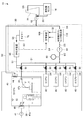
図1に示すように、本発明に係る異常検出システム10は、ダスト放射線モニタ設備20と放射線取扱施設30とを備える。
As shown in FIG. 1, an
放射線取扱施設30は、互いに独立した気密性のある複数の区画40を備える。区画40は、例えば、作業者が点検作業をすることができる作業室である。本実施形態では、区画40は、作業室とエアーロック扉のような気密扉47aと防火扉47bとによって気密性のある空間を形成している。また、本実施形態では、区画40の数は5とし、それらをそれぞれエリアAからEと呼ぶ。
The
放射線取扱施設30は、さらに、それぞれが各区画40に設けられた複数の煙検知器42を備える。つまり、エリアAの区画40には、1つの煙検知器42が設けられている。したがって、煙検知器42は雰囲気異常検知器の一例である。
The
各区画40の上部近傍の側壁には吸気口45が設けられている。また、区画40の外部には、吸気用送風機41が設けられ、吸気用送風機41から送られた空気は、吸気口45を介して、区画40の内部に強制的に送り込まれる。
An
また、各区画40の上部において、吸気口45と反対側の側壁には換気口44及び空気採取口46が備えられている。換気口44には、排気管D0の一端が気密的に接続されている。排気管D0の他端は、送風機12を介して排気筒14に気密的に接続されている。したがって、区画40の内部にある空気のほとんどは、常に、換気口44を通って排気管D0に流れる。
In addition, a
排気筒14は、排気管D0を介して送られてきた空気を排出する煙突のような廃棄施設である。排気筒14の排出口近傍には、排気筒14から排出される空気のサンプリングを行うサンプリング配管D5の一端が設けられている。サンプリング配管D5の他端には、排気筒モニタ16が気密的に設けられている。後述するように、排気管D0には、排気用配管D4が気密的に接続しているので、排気筒14には、ダスト放射線モニタ検出器で検出した空気も供給される。つまり、排気筒モニタ16は、換気口44及び空気採取口46から採取された全ての空気を監視する。
The
排気筒モニタ16は、常時、サンプリング配管D5から送られてくる空気を監視し、排気筒14から放出する排気中の放射性物質の濃度を連続して測定する。排気筒モニタ16が規定値より高い濃度を検知した場合において、他のモニタ(図示せず)は、排気筒モニタ16からの検知の情報及び他の監視情報に基づいて、排気筒14の排気を停止すべく、排気筒封鎖信号S6を排気筒14に出力するように構成されている。排気筒14は、封鎖をすべく排気筒封鎖信号S6を受信すると、直ちに、排気筒14の排気を停止する。
The
空気採取口46には、採取管D1の一端が気密的に接続されている。したがって、区画40の内部にある空気の一部は、空気採取口46を通って採取管D1に流れる。なお、採取管D1の数は、区画40の数と同一とされる。
One end of a sampling tube D1 is connected to the
複数の採取管D1には、それぞれ、複数の開閉弁50が設けられている。各開閉弁50は、後述する弁切替装置60からの開閉制御信号S1に基づいて、採取管D1に流れる空気の流量、すなわち、区画40から後述する集合配管D2への採取する空気の量を制御する。つまり、弁切替装置60は、複数の開閉弁50の開閉を個別に制御する弁制御装置である。
A plurality of on-off
複数の採取管D1の他端は、いずれも、集合配管D2に気密的に接続されている。 The other ends of the plurality of sampling pipes D1 are all airtightly connected to the collecting pipe D2.
集合配管D2には、例えば、各種香気、臭気成分を検知する高感度酸化錫系熱線型焼結半導体センサ、主に硫化水素臭を検知する超高感度酸化亜鉛系基板型薄膜半導体センサ、主にアンモニア臭を検知する超高感度酸化錫系基板型厚膜半導体センサなどが備えられている匂い検知器80が設けられている。匂い検知器80は、集合配管D2の中を流れる空気に含まれている匂いを検知し、通常とは異なる匂いを検知した場合、異常な匂いが検知されたことを示す匂い異常検知信号S4を後述する警報装置100に出力するように構成されている。
The collective pipe D2 includes, for example, a high-sensitivity tin oxide-based hot-wire sintered semiconductor sensor that detects various odors and odor components, an ultra-sensitive zinc oxide-based substrate-type thin film semiconductor sensor that mainly detects hydrogen sulfide odor, There is provided an
集合配管D2の他端には、採取ポンプ90が設けられている。採取ポンプ90は、各区画40の内部の空気を、配管D3を介してダスト放射線モニタ検出器110に送るべく、常時作動している。配管D3の一端は採取ポンプ90の出力口に気密的に接続しており、配管D3の他端はダスト放射線モニタ検出器110の採取口に気密的に接続している。
A
ダスト放射線モニタ検出器110は、常時、配管D3の中を流れる空気に含まれているダスト放射線などを監視し、それらを検知した場合、異常を検出したことを示す放射線検出信号S5を警報装置100に出力するように構成されている。
The dust
ダスト放射線モニタ検出器110の出力口には、排気用配管D4が気密的に接続されている。排気用配管D4の他端は、送風機12と換気口44との間の排気管D0に、気密的に接続している。したがって、配管D3及び排気用配管D4は、集合配管D2と同様、集合配管として作用している。
An exhaust pipe D4 is airtightly connected to the output port of the dust
弁切替装置60は、タイマー70が出力する計時信号S2に基づいて、複数の開閉弁50のうち、どの開閉弁50を開閉させるかを決定し、その決定に基づいて、その開閉弁50を開閉させる開閉制御信号S1をその開閉弁50に出力する。各開閉弁50は、受信した開閉制御信号S1に基づいて、弁を閉じたり、開けたりするように構成されている。
The
弁切替装置60は、各開閉弁50の開の状態を表す弁開情報信号S3を警報装置100に出力するように構成されている。したがって、警報装置100は、弁開情報信号S3及び匂い異常検知信号S4を受信することにより、どの区画40にどのような異常発生の兆候があるのかを異常検出システム10の管理者に報知することができるように構成されている。
The
以上の異常検出システム10は、以下のように作動する。
The above
(通常状態)
採取ポンプ90は、各区画40の内部の空気を、採取管D1、集合配管D2及び配管D3を介してダスト放射線モニタ検出器110に、常時、送る。また、匂い検知器80は、集合配管D2の内部を流れる空気を、常時、検知する。
(Normal state)
The
このとき、開になっている開閉弁50に対応する区画40の内部の空気は、採取管D1、集合配管D2、配管D3及び排気用配管D4を介して排気口120から排出されるが、閉になっている開閉弁50に対応する区画40の内部の空気は、開閉弁50によって遮断される。
At this time, the air inside the
弁切替装置60は、タイマー70からの計時信号S2に基づいて、例えば、15分経過する毎に、複数の開閉弁50のうち、開となっている開閉弁50を閉じ、それ以外の開閉弁50のうち特定の開閉弁50を開とさせるための開閉制御信号S1を各開閉弁50に出力する。
The
例えば、エリアAの区画40の内部の空気が集合配管D2の内部を流れている状態になってから15分経過すると、弁切替装置60は、開閉弁を閉とさせるための開閉制御信号S1をエリアAに対応する開閉弁50に出力し、また、開閉弁を開とさせるための開閉制御信号S1をエリアBに対応する開閉弁50に出力する。これにより、エリアBの区画40の内部の空気が集合配管D2の内部を流れるようになる。
For example, when 15 minutes have passed since the air inside the
このように、弁切替装置60は、順次、エリアB、C、D、E、Aに対応する開閉弁50を開閉させる動作を繰り返す。
In this way, the
また、弁切替装置60は、各開閉弁50の開の状態を表す弁開情報信号S3を警報装置100に出力する。
Further, the
(異常の兆候の検出時)
例えば、エリアAの区画40において、作業台Tの付近から何らかの災害発生の兆候が発生した場合、エリアAの区画40に対応する開閉弁50が開の状態であれば、作業台Tの付近から発生した災害発生の兆候を示す特有の匂いは、区画40の内部を矢印Fのように流れ、換気口44に吸い込まれる。
(When an abnormality sign is detected)
For example, in the
そして、その匂いは、採取管D1を介して、集合配管D2に流れ、匂い検知器80によって、その匂いは検知される。
Then, the odor flows to the collecting pipe D2 via the sampling tube D1, and the
匂い検知器80は、災害発生の兆候を示す特有の匂いを検知すると、異常な匂いが検知されたことを示す匂い異常検知信号S4を警報装置100に出力する。
When the
警報装置100は、匂い異常検知信号S4及び弁開情報信号S3に基づいて、災害発生の兆候を検知した区画40、すなわち、エリアAの区画40を特定し、報知する。
The
なお、エリアAの煙検知器42は、従来と同様に、匂い検知器80とは別に、災害発生の兆候を示す煙を検知する。
Note that the
このように、異常検出システム10は、従来の空調制御施設に、集合配管に匂い検知器を設けることで構成することができるので、従来の空調制御施設による災害発生の兆候を検知するほかに、さらに、複数の区画で災害発生の兆候を示す匂いの発生を1つの匂い検知で早期に検知することができる。特に、災害発生の兆候が、煙検知器42で検知しにくい匂いである場合には、匂い検知器80によって早期に災害発生の兆候を検知することができる。
In this way, the
以上、本発明の実施形態について説明したが、本発明は上述した実施形態に限るものではない。また、本発明の実施形態に記載された効果は、本発明から生じる最も好適な効果を列挙したに過ぎず、本発明による効果は、本発明の実施の形態に記載されたものに限定されるものではない。 As mentioned above, although embodiment of this invention was described, this invention is not restricted to embodiment mentioned above. The effects described in the embodiments of the present invention are only the most preferable effects resulting from the present invention, and the effects of the present invention are limited to those described in the embodiments of the present invention. It is not a thing.
D1 排気管
D2 集合配管
D3 配管
D4 排気用配管
D5 サンプリング配管
S1 開閉制御信号
S2 計時信号
S3 弁開情報信号
S4 異常検知信号
S5 放射線検出信号
S6 排気筒封鎖信号
10 異常検出システム
20 ダスト放射線モニタ設備
30 放射線取扱施設
40 区画
42 煙検知器
44 換気口
50 開閉弁
60 弁切替装置
70 タイマー
80 検知器
90 採取ポンプ
100 警報装置
110 ダスト放射線モニタ検出器
120 排気口
D1 Exhaust pipe D2 Collecting pipe D3 Pipe D4 Exhaust pipe D5 Sampling pipe S1 Opening / closing control signal S2 Timing signal S3 Valve opening information signal S4 Abnormality detection signal S5 Radiation detection signal S6 Exhaust
Claims (2)
それぞれが各区画に設けられた複数の雰囲気異常検知器と、
それぞれの一端が各区画に気密的に接続された複数の排気管と、
前記複数の排気管の他端に気密的に接続された集合配管と、
前記集合配管に設けられた採取ポンプと、
前記集合配管に設けられた匂い検知器と、を備える異常検出システム。 A plurality of independent airtight compartments;
A plurality of atmospheric anomaly detectors each provided in each compartment;
A plurality of exhaust pipes each one end of which is hermetically connected to each compartment;
A collecting pipe airtightly connected to the other ends of the plurality of exhaust pipes;
A sampling pump provided in the collecting pipe;
An abnormality detection system comprising: an odor detector provided in the collective pipe.
前記複数の開閉弁の開閉を個別に制御する弁制御装置と、を備える、請求項1に記載の異常検出システム。 Furthermore, a plurality of on-off valves each provided in each exhaust pipe,
The abnormality detection system according to claim 1, further comprising: a valve control device that individually controls opening and closing of the plurality of on-off valves.
Priority Applications (1)
| Application Number | Priority Date | Filing Date | Title |
|---|---|---|---|
| JP2010110941A JP2011237365A (en) | 2010-05-13 | 2010-05-13 | Abnormality detection system |
Applications Claiming Priority (1)
| Application Number | Priority Date | Filing Date | Title |
|---|---|---|---|
| JP2010110941A JP2011237365A (en) | 2010-05-13 | 2010-05-13 | Abnormality detection system |
Publications (1)
| Publication Number | Publication Date |
|---|---|
| JP2011237365A true JP2011237365A (en) | 2011-11-24 |
Family
ID=45325496
Family Applications (1)
| Application Number | Title | Priority Date | Filing Date |
|---|---|---|---|
| JP2010110941A Pending JP2011237365A (en) | 2010-05-13 | 2010-05-13 | Abnormality detection system |
Country Status (1)
| Country | Link |
|---|---|
| JP (1) | JP2011237365A (en) |
Cited By (2)
| Publication number | Priority date | Publication date | Assignee | Title |
|---|---|---|---|---|
| JP2016085070A (en) * | 2014-10-23 | 2016-05-19 | 株式会社東芝 | Nuclear reactor installation and accident processing method |
| JP2020501106A (en) * | 2016-09-30 | 2020-01-16 | ジョイント・ストック・カンパニー サイエンティフィック リサーチ アンド デザイン インスティテュート フォー エナジー テクノロジーズ アトムプロエクト | Monitoring system for liquid leaks from spent fuel pools |
-
2010
- 2010-05-13 JP JP2010110941A patent/JP2011237365A/en active Pending
Cited By (2)
| Publication number | Priority date | Publication date | Assignee | Title |
|---|---|---|---|---|
| JP2016085070A (en) * | 2014-10-23 | 2016-05-19 | 株式会社東芝 | Nuclear reactor installation and accident processing method |
| JP2020501106A (en) * | 2016-09-30 | 2020-01-16 | ジョイント・ストック・カンパニー サイエンティフィック リサーチ アンド デザイン インスティテュート フォー エナジー テクノロジーズ アトムプロエクト | Monitoring system for liquid leaks from spent fuel pools |
Similar Documents
| Publication | Publication Date | Title |
|---|---|---|
| US9587846B2 (en) | Ductless fume hood gas monitoring and detection system | |
| CA2856387C (en) | Multi-channel aspirated smoke detector | |
| EP2438360B1 (en) | Gas detector apparatus | |
| JP6438416B2 (en) | Real-time field gas analysis network for atmospheric monitoring and active control and response | |
| AU2015226365B2 (en) | Multi-channel detector | |
| JP2012529097A5 (en) | ||
| CN1603835A (en) | Detector with dust filter and airflow monitor | |
| KR101858054B1 (en) | System for providing air quality information | |
| KR102179129B1 (en) | An apparatus for integrated measuring stationary sources of stack exhaust gas | |
| US20130309154A1 (en) | Facility protection system including mitigation elements | |
| JP2010266077A (en) | Air cleaner, and air cleaning monitoring system using the same | |
| JP2019074237A (en) | Safety cabinet and inspection method of its exhaust duct connection | |
| CN205607957U (en) | Centralized conflagration characteristic gas detection device | |
| JP5905850B2 (en) | AIR CLEANING DEVICE AND AIR CLEANING MONITORING SYSTEM USING THE SAME | |
| JP6154831B2 (en) | Method and device for controlling dynamic sealing of an enclosure | |
| JP2011237365A (en) | Abnormality detection system | |
| JP6063186B2 (en) | Fume hood human detection sensor failure determination method and apparatus | |
| US8518166B2 (en) | Air filtering system capable of enhancing inspection convenience | |
| CN212158668U (en) | Environment monitoring device and environment monitoring system | |
| CN107667262A (en) | Ventilating system | |
| TWI790465B (en) | System and method for monitoring for the presence of volatile organic compounds | |
| Hwang et al. | Analysis of variation in total airborne bacteria concentration to assess the performance of biological safety cabinets in microbial laboratories | |
| JP2005127907A (en) | Gas detection system and compound gas detection system | |
| JP2013165597A (en) | Distribution board with corrosion protection function | |
| JP2020169763A (en) | Air conditioning system |