JP2011237301A - Irradiation control apparatus and irradiation control method of charged particle - Google Patents
Irradiation control apparatus and irradiation control method of charged particle Download PDFInfo
- Publication number
- JP2011237301A JP2011237301A JP2010109446A JP2010109446A JP2011237301A JP 2011237301 A JP2011237301 A JP 2011237301A JP 2010109446 A JP2010109446 A JP 2010109446A JP 2010109446 A JP2010109446 A JP 2010109446A JP 2011237301 A JP2011237301 A JP 2011237301A
- Authority
- JP
- Japan
- Prior art keywords
- target
- charged particle
- irradiation
- irradiation control
- charged particles
- Prior art date
- Legal status (The legal status is an assumption and is not a legal conclusion. Google has not performed a legal analysis and makes no representation as to the accuracy of the status listed.)
- Granted
Links
Images

Abstract
Description
本発明は、陽子などの荷電粒子の照射を受けて中性子を発生するターゲットに対して、当該荷電粒子の照射制御を行う照射制御装置及び照射制御方法に関するものである。 The present invention relates to an irradiation control apparatus and an irradiation control method for performing irradiation control of charged particles on a target that generates neutrons upon irradiation of charged particles such as protons.
がん治療等において、放射線治療は高い評価を受けている。特に、中性子捕捉療法(NCT:NeutronCapture Therapy)は、原理的に細胞レベルの選択的な治療の可能性があり、注目されている。NCTでは、中性子を照射したときに飛程が短く高LET(LinearEnergy Trasfer)の重荷電粒子などを発生する安定同位元素を、あらかじめ治療すべきがん細胞に取り込ませておく。その後、中性子を照射し、重荷電粒子の飛散によってがん細胞だけを選択的に破壊する。NCTに用いられる安定同位元素は、中性子と反応して高LETの重荷電粒子を発生する10Bや6Liなどであり、中性子はこれらに対して大きな反応断面積を持つ低エネルギー中性子である。現在では、NCTとして、10B及び熱中性子や熱外中性子が用いられており硼素中性子捕捉療法(BNCT:BoronNCT)と呼ばれることもある。 In cancer treatment, etc., radiation therapy is highly evaluated. In particular, neutron capture therapy (NCT) has been attracting attention because of its potential for selective treatment at the cellular level in principle. In NCT, stable isotopes that generate heavy charged particles with a short range and high LET (Linear Energy Trasfer) when irradiated with neutrons are incorporated into cancer cells to be treated in advance. Then, neutrons are irradiated to selectively destroy only cancer cells by scattering of heavy charged particles. The stable isotopes used for NCT are 10 B, 6 Li, etc., which react with neutrons to generate highly charged particles of high LET, and neutrons are low energy neutrons having a large reaction cross section. At present, 10 B, thermal neutrons, and epithermal neutrons are used as NCT and are sometimes called boron neutron capture therapy (BNCT: BoronNCT).
特許文献1には、NCTなどに用いられる中性子を発生させる装置が開示されている。この種の装置では、ターゲットに荷電粒子を照射して中性子を発生させている。中性子を発生させる際、ターゲットでは、非常に高いエネルギーレベルの荷電粒子の照射を受けるので、この入熱により熱応力が発生してしまう。そこで、特許文献1には、ターゲットに近接して、冷却水を用いた冷却機構を配置することが開示されている。 Patent Document 1 discloses a device for generating neutrons used for NCT and the like. In this type of apparatus, the target is irradiated with charged particles to generate neutrons. When generating neutrons, the target is irradiated with charged particles of a very high energy level, and thermal stress is generated by this heat input. Therefore, Patent Document 1 discloses disposing a cooling mechanism using cooling water in the vicinity of the target.
しかしながら、特許文献1に記載の冷却機構を用いる場合、冷却水を流すための設備を設けたり、冷却水を流す工程を設けたりしなければならなかった。そこで、本願発明者らは、このような冷却機構を用いることなく、ターゲットにおける熱応力の発生を抑制する手法を鋭意検討した。 However, when using the cooling mechanism described in Patent Document 1, it has been necessary to provide a facility for flowing cooling water or a process for flowing cooling water. Therefore, the inventors of the present application have intensively studied a method for suppressing the generation of thermal stress in the target without using such a cooling mechanism.
そこで、本発明は、ターゲットにおける熱応力の発生を抑制することが可能な荷電粒子の照射制御装置及び照射制御方法を提供することを目的とする。 SUMMARY OF THE INVENTION An object of the present invention is to provide a charged particle irradiation control apparatus and an irradiation control method capable of suppressing the generation of thermal stress in a target.
本発明の荷電粒子の照射制御装置は、荷電粒子の照射を受けて中性子を発生する物質からなるターゲットに対して、当該荷電粒子の照射制御を行う照射制御装置において、荷電粒子を偏向させる偏向手段と、偏向手段を制御して、荷電粒子のビームをターゲットの照射面上で周回移動させる制御手段と、を備える。 The charged particle irradiation control apparatus of the present invention is a deflection means for deflecting charged particles in an irradiation control apparatus that controls irradiation of the charged particles with respect to a target made of a substance that generates neutrons when irradiated with charged particles. And control means for controlling the deflection means to move the charged particle beam around the irradiation surface of the target.
本発明の荷電粒子の照射制御方法は、荷電粒子の照射を受けて中性子を発生する物質からなるターゲットに対して、荷電粒子の照射制御を行う照射制御方法において、荷電粒子のビームをターゲットの照射面上で周回移動させる。 The charged particle irradiation control method of the present invention is an irradiation control method for controlling irradiation of charged particles to a target made of a substance that generates neutrons upon irradiation of charged particles. Move around the surface.
この荷電粒子の照射制御装置及び照射制御方法によれば、荷電粒子のビームをターゲットの照射面上で周回移動させるので、高いエネルギーレベルの荷電粒子によるターゲットの入熱密度を軽減することができる。したがって、ターゲットの一部分に入熱が集中し、熱応力が発生することを抑制することができる。 According to this charged particle irradiation control apparatus and irradiation control method, the charged particle beam is moved around on the irradiation surface of the target, so that it is possible to reduce the heat input density of the target due to high energy level charged particles. Therefore, it is possible to suppress the heat input from being concentrated on a part of the target and generating thermal stress.
上記した制御手段は、偏向手段を制御して、荷電粒子のビーム径を拡大させることが好ましい。これによれば、荷電粒子のビーム径を拡大させるので、荷電粒子によるターゲットの入熱密度をより軽減することができ、ターゲットにおける熱応力の発生をより抑制することができる。 The above-described control means preferably controls the deflection means to enlarge the beam diameter of the charged particles. According to this, since the beam diameter of the charged particles is enlarged, the heat input density of the target by the charged particles can be further reduced, and the generation of thermal stress in the target can be further suppressed.
また、上記した制御手段は、荷電粒子のビームをターゲットの照射面上で円形状に周回移動させることが好ましい。これによれば、荷電粒子のビームの周回移動の制御が容易である。 Moreover, it is preferable that the control means described above moves the charged particle beam in a circular shape on the irradiation surface of the target. According to this, it is easy to control the circular movement of the charged particle beam.
また、上記した制御手段は、荷電粒子のビーム径を、ターゲットの照射面上でターゲットの最小外形幅の1/2に拡大させ、荷電粒子のビームの中心が、ターゲットの中心を中心とし、ターゲットの最小外形幅の1/4を半径とする円形軌道を通るように、荷電粒子のビームをターゲットの照射面上で周回移動させることが好ましい。 Further, the control means described above expands the beam diameter of the charged particles to ½ of the minimum outer shape width of the target on the target irradiation surface, and the center of the charged particle beam is centered on the center of the target. It is preferable that the charged particle beam is moved around the irradiation surface of the target so as to pass through a circular orbit having a radius of ¼ of the minimum outer width of the target.
これによれば、ターゲットの照射面上での荷電粒子のビームの重なりを低減することができる。したがって、荷電粒子によるターゲットの入熱密度をより軽減することができ、ターゲットにおける熱応力の発生をより抑制することができる。 According to this, overlapping of charged particle beams on the irradiation surface of the target can be reduced. Therefore, the heat input density of the target due to charged particles can be further reduced, and the generation of thermal stress in the target can be further suppressed.
本発明によれば、荷電粒子の照射を受けて中性子を発生するターゲットにおいて、熱応力の発生を抑制することができる。 ADVANTAGE OF THE INVENTION According to this invention, generation | occurrence | production of a thermal stress can be suppressed in the target which receives irradiation of a charged particle and generate | occur | produces a neutron.
以下、図面を参照して本発明の好適な実施形態について詳細に説明する。なお、各図面において同一又は相当の部分に対しては同一の符号を附すこととする。 DESCRIPTION OF EMBODIMENTS Hereinafter, preferred embodiments of the present invention will be described in detail with reference to the drawings. In the drawings, the same or corresponding parts are denoted by the same reference numerals.
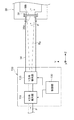
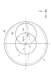
図1は、本発明の実施形態に係る荷電粒子の照射制御装置を備える中性子発生装置の構成を示す図であり、図2は、本発明の実施形態に係る荷電粒子の照射制御装置の構成を示す図である。また、図3は、ターゲットの照射面に対する荷電粒子の照射制御方法を示す図である。 FIG. 1 is a diagram illustrating a configuration of a neutron generator including a charged particle irradiation control apparatus according to an embodiment of the present invention, and FIG. 2 illustrates a configuration of a charged particle irradiation control apparatus according to an embodiment of the present invention. FIG. FIG. 3 is a diagram showing a charged particle irradiation control method for the irradiation surface of the target.
図1に示す中性子発生装置1は、例えば、中性子捕捉療法(BNCT:BoronNeutron Capture Therapy)を用いたがん治療などを行うために用いられる装置である。 A neutron generator 1 shown in FIG. 1 is an apparatus used for, for example, cancer treatment using neutron capture therapy (BNCT).
中性子発生装置1は、サイクロトロン10を備え、このサイクロトロン10は、陽子などの荷電粒子を加速して、陽子線を作り出す。サイクロトロン10は、例えば、ビーム径40mm、60kw(=30MeV×2mA)の陽子線を生成する能力を有している。
The neutron generator 1 includes a
サイクロトロン10から取り出された陽子線(以下、荷電粒子という。)Pは、例えば、水平型ステアリング12、4方向スリット14、水平垂直型ステアリング16、QM200マグネット18,19,20、90度偏向電磁石22、QM200マグネット24、水平垂直型ステアリング26、QM200マグネット28、4方向スリット30、CTモニタ32、照射制御装置100、ビームダクト34を順次に通過し、中性子発生部36に導かれる。
A proton beam (hereinafter referred to as a charged particle) P taken out from the
水平型ステアリング12、水平垂直型ステアリング16,26は、例えば電磁石を用いて荷電粒子Pのビーム軸調整を行うものである。同様に、QM200マグネット18,19,20,24,28は、例えば電磁石を用いて荷電粒子Pのビーム軸調整を行うものである。4方向スリット14,30は、端のビームを切ることにより、荷電粒子Pのビーム整形を行うものである。90度偏向電磁石22は、荷電粒子Pの進行方向を90度偏向するものである。CTモニタ32は、荷電粒子Pのビーム電流値をモニタするためのものである。
The
中性子発生部36は、図2に示すように、荷電粒子Pが照射面38aに照射されて、中性子nを出射面38bから発生するターゲット38を有する。ターゲット38は、例えば、ベリリウム(Be)からなり、直径160mmの円板状を成している。中性子発生部36で発生させた中性子nは、患者に照射されることとなる。
As shown in FIG. 2, the
また、90度偏向電磁石22には切替部40が設けられており、切替部40によって荷電粒子Pを正規の軌道から外してビームダンプ42に導くことが可能になっている。ビームダンプ42は、治療前などにおいて荷電粒子Pの出力確認を行うものである。
Further, the
次に、図2及び図3を参照して、本実施形態に係る荷電粒子の照射制御装置100及び照射制御方法について説明する。照射制御装置100は、ターゲット38に対して荷電粒子Pの照射制御を行う装置であり、X方向偏向部110と、Y方向偏向部120と、制御部130とを備える。
Next, the charged particle
X方向偏向部110は、例えば電磁石を備え、入射する荷電粒子PをX方向に偏向させて出射する。同様に、Y方向偏向部120は、例えば電磁石を備え、入射する荷電粒子PをY方向に偏向させて出射する。X方向偏向部110及びY方向偏向部120は、制御部130によって制御される。
The X
制御部130は、荷電粒子PのビームBpの径を拡大させる。本実施形態では、図3に示すように、制御部130は、荷電粒子PのビームBpの直径Dpを、ターゲット38の照射面38a上で、ターゲット38の直径(最小外形幅)Dt=160mmの略1/2の80mmに拡大させる(すなわち、40mmから80mmへ拡大)。
The
また、制御部130は、X方向偏向部110及びY方向偏向部120を制御して、荷電粒子PのビームBpをターゲット38の照射面38a上で円形状に周回移動させる。例えば、図3に示すように、制御部130は、荷電粒子PのビームBpの中心Opを円形状の周回軌道Lに沿って周回させることができる。本実施形態では、この周回軌道Lの中心OL、半径RLは、それぞれ、ターゲット38の中心Ot、ターゲット38の直径Dt=160mmの略1/4の40mmに設定されている。
Further, the
ここで、ターゲット38では、60kw(=30MeV×2mA)もの高いエネルギーレベルの荷電粒子Pの照射を受けるので、この入熱により熱応力が発生する虞がある。特に、ターゲット38は板状であるため、熱応力により変形する虞がある。
Here, since the
しかしながら、本実施形態の荷電粒子の照射制御装置100及び照射制御方法によれば、荷電粒子PのビームBpをターゲット38の照射面上で周回移動させるので、高いエネルギーレベルの荷電粒子Pによるターゲット38の入熱密度を軽減することができる。したがって、ターゲット38の一部分に入熱が集中し、熱応力が発生することを抑制することができる。なお、本実施形態では、荷電粒子PのビームBpの周回移動を円形軌道Lにすることにより、周回移動の制御を容易にしている。
However, according to the charged particle
また、本実施形態の荷電粒子の照射制御装置100及び照射制御方法によれば、荷電粒子Pのビーム径Dpを拡大させるので、荷電粒子Pによるターゲット38の入熱密度をより軽減することができ、ターゲット38における熱応力の発生をより抑制することができる。
Further, according to the charged particle
また、本実施形態の荷電粒子の照射制御装置100及び照射制御方法によれば、ターゲット38の照射面38a上での荷電粒子PのビームBpの径Dpをターゲット38の直径Dtの略1/2に拡大し、荷電粒子PのビームBpの中心Opの周回軌道Lを、ターゲット38の中心Otを中心OLとし、ターゲット38の直径Dtの略1/4を半径RLとする円形軌道とすることにより、ターゲット38の照射面38a上での荷電粒子PのビームBpの重なりを低減することができる。したがって、荷電粒子Pによるターゲット38の入熱密度をより軽減することができ、ターゲット38における熱応力の発生をより抑制することができる。
Further, according to the charged particle
なお、他の実施形態として、荷電粒子PのビームBpの中心Opの周回軌道Lの半径RLを40mmから35mmに変更設定した。これは、ビームダクト34への入熱を安全サイドで回避する目的で、荷電粒子PのビームBpの照射範囲Aをターゲット38の直径Dt=160mmより小さいφ=150mmに設定したことによる。これにより、ターゲット38の中心Ot付近において荷電粒子PのビームBpが重なることとなるが、荷電粒子PのビームBpでは中心Opからビーム周辺へ向けてエネルギーが低くなるので、ビームBpの周辺部分が重なったとしてもターゲット38の中心Ot付近に高い熱応力が発生することはない。
As another embodiment, the radius R L of the orbit L of the center Op of the beam Bp of charged particles P was changed and set to 35mm from 40 mm. This is because the irradiation range A of the beam Bp of the charged particles P is set to φ = 150 mm which is smaller than the diameter Dt = 160 mm of the
なお、本発明は上記した本実施形態に限定されることなく種々の変形が可能である。例えば、本実施形態では、荷電粒子のビームを円形状に拡大したが、円形状以外の様々な形状であってもよい。また、本実施形態では、荷電粒子の周回移動の軌道を円形状としたが、円形軌道以外の様々な周回軌道が適用可能である。 The present invention is not limited to the above-described embodiment, and various modifications can be made. For example, in the present embodiment, the beam of charged particles is enlarged in a circular shape, but various shapes other than a circular shape may be used. Further, in this embodiment, the orbit of the circular movement of the charged particles is circular, but various orbits other than the circular orbit can be applied.
また、ターゲット38としてはベリリウム(Be)に限定されず、タンタル(Ta)などを用いることもできる。この場合にも、本発明の荷電粒子の照射制御装置及び方法は効果を奏する。
The
1…中性子発生装置、10…サイクロトロン、12…水平型ステアリング、14…方向スリット、14,30…4方向スリット、16,26…水平垂直型ステアリング、18,19,20,24,28…QM200マグネット、22…90度偏向電磁石、32…CTモニタ、34…ビームダクト、36…中性子発生部、38…ターゲット、38a…照射面、38b…出射面、40…切替部、42…ビームダンプ、100…照射制御装置、110…X方向偏向部(偏向手段)、120…Y方向偏向部(偏向手段)、130…制御部(制御手段)。
DESCRIPTION OF SYMBOLS 1 ... Neutron generator, 10 ... Cyclotron, 12 ... Horizontal steering, 14 ... Direction slit, 14, 30 ... Four direction slit, 16, 26 ... Horizontal vertical steering, 18, 19, 20, 24, 28 ...
Claims (5)
前記荷電粒子を偏向させる偏向手段と、
前記偏向手段を制御して、前記荷電粒子のビームを前記ターゲットの照射面上で周回移動させる制御手段と、
を備える荷電粒子の照射制御装置。 In an irradiation control device that performs irradiation control of the charged particles with respect to a target made of a substance that generates neutrons upon irradiation with charged particles,
Deflection means for deflecting the charged particles;
Control means for controlling the deflection means to move the charged particle beam around the irradiation surface of the target;
A charged particle irradiation control apparatus comprising:
請求項1に記載の荷電粒子の照射制御装置。 The control means controls the deflection means to enlarge the beam diameter of the charged particles;
The charged particle irradiation control apparatus according to claim 1.
請求項1に記載の荷電粒子の照射制御装置。 The control means moves the charged particle beam in a circular shape on the irradiation surface of the target,
The charged particle irradiation control apparatus according to claim 1.
前記荷電粒子のビーム径を、前記ターゲットの照射面上で前記ターゲットの最小外形幅の1/2に拡大させ、
前記荷電粒子のビームの中心が、前記ターゲットの中心を中心とし、前記ターゲットの最小外形幅の1/4を半径とする円形軌道を通るように、前記荷電粒子のビームを前記ターゲットの照射面上で周回移動させる、
請求項2に記載の荷電粒子の照射制御装置。 The control means includes
Increasing the beam diameter of the charged particles to ½ of the minimum outer width of the target on the irradiation surface of the target,
The charged particle beam is placed on the irradiation surface of the target so that the center of the charged particle beam passes through a circular trajectory centered on the center of the target and having a radius of ¼ of the minimum outer width of the target. To move around,
The charged particle irradiation control apparatus according to claim 2.
前記荷電粒子のビームを前記ターゲットの照射面上で周回移動させる、
荷電粒子の照射制御方法。 In an irradiation control method for performing irradiation control of a charged particle on a target made of a substance that generates neutrons upon irradiation of the charged particle,
Moving the charged particle beam around the irradiation surface of the target;
Charged particle irradiation control method.
Priority Applications (1)
| Application Number | Priority Date | Filing Date | Title |
|---|---|---|---|
| JP2010109446A JP5490608B2 (en) | 2010-05-11 | 2010-05-11 | Neutron generator and control method for neutron capture therapy |
Applications Claiming Priority (1)
| Application Number | Priority Date | Filing Date | Title |
|---|---|---|---|
| JP2010109446A JP5490608B2 (en) | 2010-05-11 | 2010-05-11 | Neutron generator and control method for neutron capture therapy |
Publications (2)
| Publication Number | Publication Date |
|---|---|
| JP2011237301A true JP2011237301A (en) | 2011-11-24 |
| JP5490608B2 JP5490608B2 (en) | 2014-05-14 |
Family
ID=45325447
Family Applications (1)
| Application Number | Title | Priority Date | Filing Date |
|---|---|---|---|
| JP2010109446A Expired - Fee Related JP5490608B2 (en) | 2010-05-11 | 2010-05-11 | Neutron generator and control method for neutron capture therapy |
Country Status (1)
| Country | Link |
|---|---|
| JP (1) | JP5490608B2 (en) |
Cited By (2)
| Publication number | Priority date | Publication date | Assignee | Title |
|---|---|---|---|---|
| WO2013002304A1 (en) * | 2011-06-30 | 2013-01-03 | 株式会社Quan Japan | Neutron beam generating device and neutron beam generating method |
| CN113450940A (en) * | 2020-03-24 | 2021-09-28 | 住友重机械工业株式会社 | Irradiation control device for charged particles |
Families Citing this family (1)
| Publication number | Priority date | Publication date | Assignee | Title |
|---|---|---|---|---|
| JP6605221B2 (en) * | 2015-03-31 | 2019-11-13 | 住友重機械工業株式会社 | Neutron capture therapy device |
Citations (3)
| Publication number | Priority date | Publication date | Assignee | Title |
|---|---|---|---|---|
| JPS56152199A (en) * | 1980-03-31 | 1981-11-25 | Siemens Ag | Charged particle accelerator |
| JP2002249830A (en) * | 2001-02-26 | 2002-09-06 | Nippon Mining & Metals Co Ltd | Electron-beam melting method and method for using material obtained by this method |
| JP2006047115A (en) * | 2004-08-04 | 2006-02-16 | Mitsubishi Heavy Ind Ltd | Neutron generating apparatus, target and neutron irradiation system |
-
2010
- 2010-05-11 JP JP2010109446A patent/JP5490608B2/en not_active Expired - Fee Related
Patent Citations (3)
| Publication number | Priority date | Publication date | Assignee | Title |
|---|---|---|---|---|
| JPS56152199A (en) * | 1980-03-31 | 1981-11-25 | Siemens Ag | Charged particle accelerator |
| JP2002249830A (en) * | 2001-02-26 | 2002-09-06 | Nippon Mining & Metals Co Ltd | Electron-beam melting method and method for using material obtained by this method |
| JP2006047115A (en) * | 2004-08-04 | 2006-02-16 | Mitsubishi Heavy Ind Ltd | Neutron generating apparatus, target and neutron irradiation system |
Cited By (6)
| Publication number | Priority date | Publication date | Assignee | Title |
|---|---|---|---|---|
| WO2013002304A1 (en) * | 2011-06-30 | 2013-01-03 | 株式会社Quan Japan | Neutron beam generating device and neutron beam generating method |
| JP2013016283A (en) * | 2011-06-30 | 2013-01-24 | Quan Japan Inc | Neutron beam generator and method of generating neutron beam |
| CN113450940A (en) * | 2020-03-24 | 2021-09-28 | 住友重机械工业株式会社 | Irradiation control device for charged particles |
| KR20210119300A (en) | 2020-03-24 | 2021-10-05 | 스미도모쥬기가이고교 가부시키가이샤 | Device for controlling irradiation of charged particle |
| US11545328B2 (en) | 2020-03-24 | 2023-01-03 | Sumitomo Heavy Industries, Ltd. | Irradiation control device for charged particles |
| JP7465697B2 (en) | 2020-03-24 | 2024-04-11 | 住友重機械工業株式会社 | Charged particle irradiation control device |
Also Published As
| Publication number | Publication date |
|---|---|
| JP5490608B2 (en) | 2014-05-14 |
Similar Documents
| Publication | Publication Date | Title |
|---|---|---|
| EP2026640B1 (en) | Particle beam therapy system | |
| JP4474549B2 (en) | Irradiation field forming device | |
| JP4873563B2 (en) | Particle accelerator, operation method thereof, and particle beam irradiation apparatus | |
| JP4988516B2 (en) | Particle beam therapy system | |
| WO2013065762A1 (en) | Radiation emission device, radiation emission method, and program storage medium | |
| JP5726541B2 (en) | Energy degrader and charged particle irradiation system including the same | |
| JP2009236867A (en) | Charged particle beam irradiating apparatus | |
| JP6200368B2 (en) | Charged particle irradiation system and control method of charged particle beam irradiation system | |
| WO2006064613A1 (en) | Charged particle beam irradiator and rotary gantry | |
| JP6257994B2 (en) | Neutron generator and medical accelerator system | |
| JP2012099354A (en) | Particle accelerator and bnct device | |
| JP5490608B2 (en) | Neutron generator and control method for neutron capture therapy | |
| JP5380693B2 (en) | Charged particle beam irradiation apparatus and control method of charged particle beam apparatus | |
| KR102178632B1 (en) | Neutron Capture and Therapy Device with Multiple Compact Cyclotron and control method for that | |
| JP6266399B2 (en) | Neutron capture therapy device | |
| JP2018146265A (en) | Electron beam irradiation device and method for operating electron beam irradiation device | |
| TWI811649B (en) | Charged Particle Irradiation Control Device | |
| US10535441B1 (en) | Method of irradiating a target | |
| JP6266092B2 (en) | Particle beam therapy system | |
| CN111585162B (en) | Gamma light generating device and radioisotope production device | |
| JP2018011872A (en) | Neutron capture therapy system | |
| US20230268096A1 (en) | Systems, devices, and methods for multi-directional dipole magnets and compact beam systems | |
| JP7072196B1 (en) | Low-energy charged particle beam transport system and charged particle beam transport method in BNCT | |
| EP4029562A1 (en) | Particle beam irradiation system and particle beam irradiation facility | |
| JP2004121654A (en) | Apparatus for irradiating electric charged particle for medical use |
Legal Events
| Date | Code | Title | Description |
|---|---|---|---|
| A621 | Written request for application examination |
Free format text: JAPANESE INTERMEDIATE CODE: A621 Effective date: 20120713 |
|
| A977 | Report on retrieval |
Free format text: JAPANESE INTERMEDIATE CODE: A971007 Effective date: 20131007 |
|
| A131 | Notification of reasons for refusal |
Free format text: JAPANESE INTERMEDIATE CODE: A131 Effective date: 20131015 |
|
| A521 | Written amendment |
Free format text: JAPANESE INTERMEDIATE CODE: A523 Effective date: 20131205 |
|
| TRDD | Decision of grant or rejection written | ||
| A01 | Written decision to grant a patent or to grant a registration (utility model) |
Free format text: JAPANESE INTERMEDIATE CODE: A01 Effective date: 20140225 |
|
| A61 | First payment of annual fees (during grant procedure) |
Free format text: JAPANESE INTERMEDIATE CODE: A61 Effective date: 20140226 |
|
| R150 | Certificate of patent or registration of utility model |
Ref document number: 5490608 Country of ref document: JP Free format text: JAPANESE INTERMEDIATE CODE: R150 |
|
| LAPS | Cancellation because of no payment of annual fees |