JP2011237161A - Humidifier - Google Patents
Humidifier Download PDFInfo
- Publication number
- JP2011237161A JP2011237161A JP2010170801A JP2010170801A JP2011237161A JP 2011237161 A JP2011237161 A JP 2011237161A JP 2010170801 A JP2010170801 A JP 2010170801A JP 2010170801 A JP2010170801 A JP 2010170801A JP 2011237161 A JP2011237161 A JP 2011237161A
- Authority
- JP
- Japan
- Prior art keywords
- vibrator
- float
- water storage
- storage container
- water
- Prior art date
- Legal status (The legal status is an assumption and is not a legal conclusion. Google has not performed a legal analysis and makes no representation as to the accuracy of the status listed.)
- Granted
Links
Images


Classifications
-
- F—MECHANICAL ENGINEERING; LIGHTING; HEATING; WEAPONS; BLASTING
- F24—HEATING; RANGES; VENTILATING
- F24F—AIR-CONDITIONING; AIR-HUMIDIFICATION; VENTILATION; USE OF AIR CURRENTS FOR SCREENING
- F24F6/00—Air-humidification, e.g. cooling by humidification
- F24F6/12—Air-humidification, e.g. cooling by humidification by forming water dispersions in the air
Abstract
Description
本発明は、加湿器に関し、より詳しくは、水を粒子化させる振動子を浮上させるフロート(float)が一体結合されている超音波加湿器に関する。 The present invention relates to a humidifier, and more particularly to an ultrasonic humidifier in which a float that floats a vibrator that forms water particles is integrally coupled.
室内で長い間生活しながら、室内の乾燥している空気を持続的に吸入するようになれば、各種の呼吸器疾患を誘発する原因となる。したがって、室内湿度を適正な水準に維持するために水を粒子化して室内に吹き付けられるようにする加湿器を使用するようになる。 If you continue to inhale the dry air indoors while living indoors for a long time, it will cause various respiratory diseases. Therefore, in order to maintain the indoor humidity at an appropriate level, a humidifier that uses water to be sprayed into the room is used.
一般に、よく使われる超音波加湿器は、電気回路で作られた超音波信号を水中に沈んでいる振動子に加えれば、振動子が振動して超音波を発生させるようになり、このような振動の効果により水が微細な粒子(水蒸気)になって吹き付けられるようになる。 In general, a commonly used ultrasonic humidifier adds an ultrasonic signal generated by an electrical circuit to a vibrator that is submerged in water, and the vibrator vibrates to generate ultrasonic waves. Due to the vibration effect, water is sprayed as fine particles (water vapor).
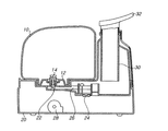
図1には、従来技術による加湿器の構成が図示されている。 FIG. 1 shows the configuration of a humidifier according to the prior art.
上記の図面によれば、従来技術による超音波加湿器は、大別して水を貯蔵する貯水タンク10、振動子と送風機等の各種部品が設けられるベース20、そして粒子化した水を外部に吐出されるように案内する噴霧管30と噴霧ノズル32から構成される。
According to the above drawings, the ultrasonic humidifier according to the prior art is roughly divided into a
上記貯水タンク10には水を投入するための蓋12が備えられる。上記蓋12には排水口14が設けられている。上記排水口14の内側にはスプリング(図示せず)が設けられているので、平常時には排水口14を蓋12の外側に押し上げるようになり、これによって排水口14と蓋12との間の空間を密閉させるようになって、水が貯水タンク10の外方へ流れ出ないようにする。
The
上記ベース20には、水を粒子化させる振動子24、上記振動子24と電気的に連結されて上記振動子24に電気信号と電源を供給する回路部(図示せず)、及び粒子化した水を外部に吐出させるためにエアーフローを発生させる送風機28を含んで構成される。そして、上記貯水タンク10がベース20に安着すれば、上記排水口14を貯水タンク10の内側に押込むための突起22が形成されている。
The
噴霧管30は略円筒形状で形成され、粒子化した水を送風機28により発生されたエアーフローにより外部に吐出されるように案内する役目をする。噴霧ノズル32は上記噴霧管30の上側に挟まれて、希望する方向に回転可能に構成されて、水蒸気が吐出される方向を使用者が変更させることができるように構成されている。
The
従来技術による超音波加湿器による動作を見れば、使用者が水が貯蔵されている貯水タンク10をベース20に上げて置けば、ベース20の底に設けられた突起22が蓋12に設けられている排水口14を貯水タンク10の内側に押込むようになる。この際、排水口14と蓋12との間に空間ができて貯水タンク10の水が振動子24が設けられた貯水部26に流れ出るようになる。そして、使用者が加湿器を動作させれば、振動子24が水を粒子化するようになり、送風機28が作動してエアーフローを発生させれば、噴霧管30と噴霧ノズル32を通じて水蒸気が外部に吐出される。
If the operation by the ultrasonic humidifier according to the prior art is seen, if the user raises the
しかしながら、前述したような従来の技術によれば、次のような問題点がある。 However, the conventional techniques as described above have the following problems.
即ち、従来の超音波加湿器を持続的に使用するようになれば、貯水タンク10及びベース20の貯水部26に溜まっている水に細菌や黴などが繁殖して汚染が発生するようになる。したがって、室内空気汚染の原因となる。
In other words, if the conventional ultrasonic humidifier is used continuously, bacteria, spiders, etc. propagate in the water stored in the
これを防止するために、貯水タンク10及びベース20を持続的に洗浄しなければならないが、貯水タンクの構造上、清潔に洗浄することが困難である。そして、振動子24が設けられている貯水部26も持続的な洗浄を必要とするが、これを洗浄するためにはベース20の全体を移動させなければならない面倒さがあり、完全に絶縁されていない回路基板などに水が染み込んで加湿器全体の故障の原因となることもある。したがって、使用者が加湿器を清潔に維持できないことによって、既に汚染された水が新しく交換した水と混合されて室内空気を加湿するようになり、これによって室内空気の汚染状態がより悪くなる。
In order to prevent this, the
前述した従来技術の問題点を解決するために、本発明は、室内空気の湿度を調節する加湿器において、水を貯蔵する貯水容器の洗浄を便利にして衛生的な室内環境を維持するようにすることをその目的とする。 In order to solve the above-described problems of the prior art, the present invention provides a humidifier that adjusts the humidity of room air so that the water storage container for storing water can be conveniently cleaned to maintain a sanitary indoor environment. The purpose is to do.
本発明の他の目的は、超音波振動子によって生成される蒸気粒子のうち、微細な粒子のみが外部に供給される微細加湿が可能な加湿器を提供することにある。 Another object of the present invention is to provide a humidifier capable of fine humidification in which only fine particles among vapor particles generated by an ultrasonic vibrator are supplied to the outside.
前述した目的を達成するために、本発明は、水を貯蔵し、上面が開いた貯水容器と、上記貯水容器の上部を開閉可能で、蒸気を外部に排出する排出口が備えられたキャップ部と、上記キャップ部の下端に結合され、水を粒子化させる蒸気発生手段と、を含む。 In order to achieve the above-mentioned object, the present invention stores a water and opens a top surface of a water storage container, and a cap part that can open and close the upper part of the water storage container and has a discharge port for discharging steam to the outside. And a steam generating means coupled to the lower end of the cap portion for making water into particles.
そして、上記蒸気発生手段に対する実施形態によれば、一定の浮力を有するフロートと、上記フロートと連動し、上記フロートの下部に設けられる振動子と、を含んで構成される。 And according to embodiment with respect to the said steam generation means, it is comprised including the float which has fixed buoyancy, and the vibrator | oscillator provided in the lower part of the said float in conjunction with the said float.
上記蒸気発生手段に対する他の実施形態によれば、上記キャップ部の下端に設けられるガイド部と、上記ガイド部の下部に設けられて蒸気を発生させる振動子と、を含んで構成される。 According to another embodiment of the steam generating means, the guide part is configured to include a guide part provided at a lower end of the cap part and a vibrator provided at a lower part of the guide part to generate steam.
そして、上記蒸気発生手段に対する更に他の実施形態によれば、上記キャップ部の下端に設けられるガイド部と、上記ガイド部によって上下移動が案内されるフロート、上記フロートの下部に設けられてフロートと連動する振動子を含んで構成できる。 According to still another embodiment of the steam generating means, a guide part provided at the lower end of the cap part, a float guided by the guide part for vertical movement, a float provided at the lower part of the float, It can be configured to include an interlocking transducer.
ここで、上記ガイド部は、上記フロートを案内する垂直状の案内部と、上記案内部の下端部に設けられて上記振動子の最低位置を規制する底面から構成されることが好ましい。 Here, it is preferable that the guide portion includes a vertical guide portion that guides the float and a bottom surface that is provided at a lower end portion of the guide portion and restricts the lowest position of the vibrator.
そして、本発明の加湿器は、水位を感知して上記振動子のオンオフを制御するための水位感知センサをさらに含む。 The humidifier according to the present invention further includes a water level sensor for sensing the water level and controlling on / off of the vibrator.
上記キャップ部は、吸入口が形成される下部板と、上記吸入口と対応する位置に吐出口が形成される上部板を含んで構成され、上記吸入口と上記吐出口とは互いに連結されて上記貯水容器の内部から発生した蒸気が外部に排出される排出口を形成するようになる。 The cap portion includes a lower plate in which a suction port is formed, and an upper plate in which a discharge port is formed at a position corresponding to the suction port. The suction port and the discharge port are connected to each other. The steam generated from the inside of the water storage container forms an outlet for discharging to the outside.
そして、上記キャップ部の内部には上記貯水容器の内部にエアーフローを発生させるためのファンが備えられる。ここで、上記ファンによって発生するエアーフローは上記貯水容器の内部で旋回流を形成することが好ましい。 In addition, a fan for generating an air flow in the water storage container is provided in the cap portion. Here, it is preferable that the air flow generated by the fan forms a swirl flow inside the water storage container.
本発明の他の実施形態によれば、上記キャップ部の上部には取っ手が設けられる。 According to another embodiment of the present invention, a handle is provided on the top of the cap portion.
本発明の更に他の実施形態によれば、上記案内部は長手方向にスリットが形成された円筒状で形成され、上記底面は円筒状の案内部の内部に形成され、上記フロートはリング形状で形成され、上記振動子は上記フロートの中央下部に上記フロートと一体で連結されて設けられ、上記フロートと上記振動子との間に形成された空間に上記案内部が挟まれて水位によって上下移動を案内し、上記底面が上記振動子の最低位置を規制する。 According to still another embodiment of the present invention, the guide portion is formed in a cylindrical shape with a slit formed in a longitudinal direction, the bottom surface is formed in a cylindrical guide portion, and the float is in a ring shape. The vibrator is formed integrally connected to the float at the lower center of the float, and the guide portion is sandwiched in a space formed between the float and the vibrator, and moves up and down depending on the water level. The bottom surface regulates the lowest position of the vibrator.
本発明による超音波加湿器は、キャップの下部に蒸気発生装置が設けられているため、キャップを貯水容器から分離することによって実質的に上面の全体が開放された貯水容器だけで分離することが可能である。したがって、貯水容器の内部を清潔に清掃することが可能になる長所を期待することができる。 In the ultrasonic humidifier according to the present invention, since the steam generator is provided at the lower portion of the cap, the cap can be separated from the water storage container only by the water storage container whose upper surface is substantially opened. Is possible. Therefore, it is possible to expect an advantage that the inside of the water storage container can be cleaned cleanly.
そして、本発明によれば、ファンで形成されるエアーフローが貯水容器の内部で旋回流を形成するように構成することが可能である。貯水容器の内部で旋回流が形成されれば、相対的に大きくて重い蒸気粒子は自重により下方に落ちて、微細な粒子のみ排出口を通じて外部に供給できるようになって、実質的に微細加湿が可能であるという長所も期待できる。 And according to this invention, it is possible to comprise so that the airflow formed with a fan may form a swirl flow inside a water storage container. If a swirl flow is formed inside the water storage container, relatively large and heavy vapor particles fall downward due to their own weight, and only fine particles can be supplied to the outside through the discharge port. The advantage of being possible is also expected.
以下、本発明に従う加湿器の好ましい実施形態を添付図面を参考しつつ詳細に説明する。 Hereinafter, preferred embodiments of a humidifier according to the present invention will be described in detail with reference to the accompanying drawings.
図2は本発明の具体的な実施形態に係る加湿器の全体外観を示す斜視図であり、図3は本発明の具体的な実施形態に係る加湿器の内部構成を示す概略断面図であり、図4は本発明に係る加湿器の分解状態斜視図である。 FIG. 2 is a perspective view showing an overall appearance of a humidifier according to a specific embodiment of the present invention, and FIG. 3 is a schematic cross-sectional view showing an internal configuration of the humidifier according to a specific embodiment of the present invention. FIG. 4 is an exploded perspective view of the humidifier according to the present invention.
上記の図面に示すように、本実施形態の加湿器は、水を貯蔵し、上面に開口された貯水容器200、上記貯水容器200の上部を開閉し、蒸気が排出される排出口が形成されたキャップ部300、及び上記キャップ部300の下端に結合され、水を粒子化させる蒸気発生部100を含んで構成される。
As shown in the drawings, the humidifier according to the present embodiment stores water, opens a
本実施形態の貯水容器200は略円筒形状の容器であり、上面が開放されている。このように貯水容器200の上面の全体が開放されているため、実際に貯水容器200の内部の掃除が非常に容易である。このような貯水容器200の上面はキャップ部300により開閉される。即ち、キャップ部300を分離して貯水容器200の内部に水を供給するか、内部の掃除が可能である。
The
本実施形態の蒸気発生部100はキャップ部300の下部に取り付けられている。したがって、上記キャップ部300を貯水容器200から分離するようになれば、図4に示すように、上記蒸気発生部100もキャップ部300と共に貯水容器200から分離される。
The
上記蒸気発生部100は、超音波を発生させて水を粒子化させる振動子110と、水位を感知して加湿器の動作を中断させるようにする水位感知センサ130と、上記振動子110を一定の深さの水中で維持するために一定の浮力を有するフロート150と、を含む。
The
上記フロート150は略リング形状からなる。上記フロート150の中央部分には上記振動子110が上記フロート150と結合される。例えば、上記フロート150の内部で形成される連結アーム152が上記振動子110と結合されることによって、上記フロート150と振動子110とが互いに連動できるように結合できる。この際、上記振動子110は上記フロート150より一定の高さだけ下方に設けられる。即ち、上記フロート150が水面に浮かぶようになれば、上記振動子110は定まった深さの水中に沈めるように設けられるものである。そして、上記水位感知センサ130は上記振動子110の上面に設けられている。
The
上記振動子110及びフロート150は、キャップ部300の底面に取り付けられるガイド部170によって上下方向への移動がガイドされる。上記ガイド部170は略薄い円筒状で中央部分には長手方向にスリットが形成されることによって形成される案内部172を具備している。そして、上記ガイド部170の案内部172の下端の内部は底面174を形成している。
The
上記案内部172は、上記フロート150の内側と上記振動子110の外側との間に形成された空間に挟まれて、貯水容器200の内部の水位が変わることによって振動子110及びフロート150が上下方向に移動できるように案内する役目をする。上記底面174には貯水容器200の水が一定量以下に落ちた時、上記振動子110が安着される。即ち、上記底面174により上記振動子110の最低位置が規制される。そして、上記案内部172の上端部は後述するキャップ部300の下端に結合される。したがって、キャップ部300の取っ手350を持ち上げると、キャップ部300、ガイド部170、及び蒸気発生部100が一緒に持ち上げられるようになる。
The
そして、図示した実施形態において、上記振動子110は案内部172の内部に位置し、上記振動子110と共に連結されるフロート150は案内部172の外側に位置していることが分かる。したがって、上記キャップ部300を持ち上げると、キャップ部300の下端部に付着された上記ガイド部170と共に上記振動子110及びフロート150が貯水容器200から除去できる。
In the illustrated embodiment, the
上記水位感知センサ130は、上記フロート150より一定の高さだけ下方に位置される。したがって、上記フロート150が上記振動子110を浮上させることができない位に貯水容器200内に残っている水が少なければ、上記水位感知センサ130は空気中に露出されて水がないことを感知するようになって、回路部に振動子110の動作を遮断するように電気信号を発生させる。
The
そして、貯水容器200の開放された上部はキャップ部300により開閉される。上記キャップ部300は、吸入口320が形成された下部板310と、吐出口340と取っ手350が形成された上部板330と、から構成される。上記吸入口320は水蒸気が外方に吹き付けられるように上方に凹まれるように形成される。そして、上部板330には下部板310の吸入口320と対応する位置に成形された吐出口340は下方に凹まれるように形成されている。
The opened upper part of the
上記上部板330と上記下部板310とが互いに結合されれば、吸入口320と吐出口340とは互いに連結されて、貯水容器200の内部から発生した蒸気を外部に排出する排出口(A)を形成する。
If the
そして、キャップ部300の内部にはファン360が設けられている。上記ファン360は貯水容器200の内部にエアーフローを発生させるためのものである。即ち、上記ファン360が設けられた部分に対応する下部板310には孔が形成されているので、上記ファン360から発生するエアーフローを貯水容器200の内部に供給するようになる。そして、上記ファン360が動作するか否か、または振動子110が動作するか否かなどを制御するための回路基板(回路部)370も上記キャップ部300の内部に設置できる。
A
したがって、使用者が加湿器を動作させれば、上記キャップ部300の内部に設けられたファン360によりエアーフローが発生し、上記ファン360が設けられた下部板310の底面に形成された孔(図示せず)により貯水容器200の内部にエアーフローが供給される。この際、発生したエアーフローにより振動子110によって発生された水蒸気が吸入口320及び吐出口340から構成される排出口(A)に沿って外部に吹き付けられるようになる。即ち、上記吸入口320と吐出口340とが協力して水蒸気を外部に排出するように案内する役目をする。
Therefore, when the user operates the humidifier, an air flow is generated by the
ここで、上記ファン360によって上記貯水容器200の内部に供給されるエアーフローについて説明する。ファン360から発生するエアーフローは、上記貯水容器200の内部で旋回流が形成されるようにすることが好ましい。上記貯水容器200の内部で旋回流が発生するようになれば、蒸気粒子のうち、相対的に軽い粒子、即ち最も微細な粒子が前述した排出口(A)を通じて外部に抜け出すようになり、実際に重い粒子は自重により下方に沈むようになる。したがって、上記ファン360により貯水容器200の内部から発生した旋回流により微細な蒸気粒子のみ排出口(A)を通じて抜け出すようになって、実質的に微細加湿が可能であるという長所が期待できる。
Here, the air flow supplied to the inside of the
ここで、ファン360で形成されるエアーフローが貯水容器200の内部で旋回流を形成できるようにするためには、上記ファン360の位置を貯水容器200の円周方向に沿って傾斜するように調節することも可能であり、ファン360で生成されるエアーフローを貯水容器200の内部で円周方向に沿って流れるように別のガイドを上記下部板310に形成することも可能である。
Here, in order to allow the air flow formed by the
そして、上記上部板330の上側には取っ手350が形成されている。上記取っ手350は上記上部板330の両端部に結合される。取っ手350の中央部分と上部板330の中央部分には空間が形成されているので、使用者が上記空間に手を入れることができる。したがって、容易にキャップ部300を持ち上げることができる役目をする。
A
上記貯水容器200の両側内部の上端には掛止突起210が形成されている。そして、上記下部板310の両側面の下端には上記掛止突起210が挟まれることができるように掛止スリット380が形成されている。上記掛止スリット380は上下方向に溝が形成された挿入部382と、上記挿入部382に対し、直角方向に溝が形成された安着部384と、から構成される。使用者が上記キャップ部300を使用して上記貯水容器200を閉じる場合、上記貯水容器200に形成された掛止突起210が上記下部板310に形成された挿入部382に入るように閉じなければならない。そして、上記キャップ部300を上記安着部384が形成された方向に回転させると、上記キャップ部300と貯水容器200とは掛止される。したがって、上記キャップ部300と貯水容器200が掛かった状態で上記キャップ部300を持ち上げると、上記貯水容器200も共に持ち上げられるようになる。
A hooking
上記キャップ部300と貯水容器200が掛かった状態で上記キャップ部300を解除しようとする場合には、前述した動作を逆に遂行すればよい。即ち、上記キャップ部300を安着部384が形成された反対方向に回転させて、上記挿入部382が形成された所に位置させた後、上記キャップ部300を持ち上げればよい。
When the
そして、蒸気の発生のための振動子110と上記回路部370とは電気的に連結される。一例として電線により連結されることを考えることができる。この際、上記電線は、当然防水が十分に可能なものを使用しなければならず、振動子110との連結部分も、例えばシリコンコーティングなどにより十分に防水処理されなければならない。
The
以下、上記したような本発明の具体的な実施形態による加湿器の作用を詳細に説明する。まず、本発明による加湿器を使用して加湿器が動作する過程について詳細に説明する。 Hereinafter, the operation of the humidifier according to the specific embodiment of the present invention as described above will be described in detail. First, a process in which the humidifier operates using the humidifier according to the present invention will be described in detail.
貯水容器200に一定量の水が貯蔵されており、使用者が加湿器の動作ボタンを作動させれば、回路部370から発生した電気信号が振動子110に送られるようになる。これによって、振動子110が振動するようになって超音波を発生させれば、水が粒子化して吹き付けられるようになる。そして、キャップ部300に設けられたファン360が動作しながら貯水容器200の内部にエアーフローを起こすようになる。この際、粒子化した水(水蒸気)はファン360により発生したエアーフローにより下部板310の吸入口320を経て上部板330の吐出口340を通じて外部に噴出されるようになる。
When a certain amount of water is stored in the
ここで、前述したように、上記ファン360により発生するエアーフローが貯水容器200の内部で旋回流を形成するようになれば、振動子110により生成された蒸気粒子のうち、相対的に大きくて重い粒子は旋回する途中で自重によって下方に落ちるようになり、相対的に小さくて微細な粒子のみが排出口(A)を通じて外部に供給できる。
Here, as described above, if the air flow generated by the
そして、貯水容器200の水が振動子110の動作により徐々に水位が低くなると、フロート150と振動子110は上記ガイド部170の案内部172に沿って下方に降りるようになる。そして、貯水容器200に残っている水が一定量よりも少なければ、振動子110はガイド部170の底面174に安着される。加湿器が続けて動作して水位がより低くなると、蒸気発生部100に設けられた水位感知センサ130がこれを感知するようになり、この信号を回路部370に伝達する。上記信号の伝達を受けた回路部370は振動子110の動作を停止させる電気信号を送るようになり、振動子110は動作を止めるようになる。
When the water level of the
次に、本発明による加湿器を洗浄する過程について詳細に説明する。 Next, the process of cleaning the humidifier according to the present invention will be described in detail.
貯水容器200に貯蔵された水が全て使われるか、使用者が加湿器を洗浄しようとする場合、上部板330に形成された取っ手350を安着部384が形成された反対方向に回転させ、挿入部382に沿って持ち上げると、上記キャップ部300、上記下部板310に挟まれたガイド部170、及びガイド部170の底面174に載せられた蒸気発生部100が共に持ち上げられるようになる。この際、下部板310に挟まれたガイド部170も分離可能である。したがって、上記部品が分離された貯水容器200とガイド部170は使用者が容易に洗浄可能な状態となる。また、蒸気発生部100も上記部品と分離されて洗浄が容易な状態となる。したがって、使用者が貯水容器200と蒸気発生部100を容易に洗浄することができるので、清潔な部品管理が可能になるにつれて、加湿器の使用による清潔な室内空気が維持できる。
When all the water stored in the
本発明の権利は前述した実施形態に限定されず、特許請求の範囲に記載されたことにより定義され、本発明の分野で通常の知識を有する者が特許請求の範囲に記載された権利範囲内で多様な変形と改作が可能であることは自明である。 The right of the present invention is not limited to the above-described embodiment, but is defined by what is described in the claims, and those who have ordinary knowledge in the field of the present invention fall within the scope of the right described in the claims. It is obvious that various modifications and adaptations are possible.
100:蒸気発生部 110:振動子 130:水位感知センサ 150:フロート 170:ガイド部 172:案内部 174:底面 200:貯水容器 300:キャップ部 310:下部板 320:吸入口 330:上部板 340:吐出口 350:取っ手 360:ファン (A):排出口 DESCRIPTION OF SYMBOLS 100: Steam generation part 110: Vibrator 130: Water level detection sensor 150: Float 170: Guide part 172: Guide part 174: Bottom surface 200: Water storage container 300: Cap part 310: Lower plate 320: Inlet port 330: Upper plate 340: Discharge port 350: Handle 360: Fan (A): Discharge port
Claims (12)
前記貯水容器の上部を開閉可能で、前記貯水容器の内部から発生した蒸気を外部に排出する排出口が備えられたキャップ部と、
前記キャップ部の下端に結合され、水を粒子化させる蒸気発生手段と、
を含むことを特徴とする加湿器。 A water storage container for storing water and having an open top surface;
A cap part provided with a discharge port capable of opening and closing the upper part of the water storage container and discharging steam generated from the inside of the water storage container to the outside;
A steam generating means coupled to the lower end of the cap part to make water particles;
The humidifier characterized by including.
前記底面は円筒状の前記案内部の内部に形成され、
前記フロートはリング形状で形成され、
前記振動子は前記フロートの中央の下部に前記フロートと一体で連結されて設けられ、
前記フロートと前記振動子との間に形成された空間に前記案内部が挟まれて水位によって上下移動を案内し、
前記底面が前記振動子の最低位置を規制することを特徴とする請求項5に記載の加湿器。 The guide portion is formed in a cylindrical shape with a slit formed in the longitudinal direction,
The bottom surface is formed inside the cylindrical guide portion,
The float is formed in a ring shape,
The vibrator is integrally connected to the float at the lower center of the float,
The guide portion is sandwiched in a space formed between the float and the vibrator to guide the vertical movement by the water level,
The humidifier according to claim 5, wherein the bottom surface regulates a lowest position of the vibrator.
Applications Claiming Priority (4)
| Application Number | Priority Date | Filing Date | Title |
|---|---|---|---|
| KR1020100044555A KR20110125028A (en) | 2010-05-12 | 2010-05-12 | A humidifer |
| KR10-2010-0044555 | 2010-05-12 | ||
| KR1020100065964A KR101293556B1 (en) | 2010-07-08 | 2010-07-08 | A Cyclone Humidifier having minute humidification function |
| KR10-2010-0065964 | 2010-07-08 |
Publications (2)
| Publication Number | Publication Date |
|---|---|
| JP2011237161A true JP2011237161A (en) | 2011-11-24 |
| JP5156802B2 JP5156802B2 (en) | 2013-03-06 |
Family
ID=44541438
Family Applications (1)
| Application Number | Title | Priority Date | Filing Date |
|---|---|---|---|
| JP2010170801A Expired - Fee Related JP5156802B2 (en) | 2010-05-12 | 2010-07-29 | humidifier |
Country Status (2)
| Country | Link |
|---|---|
| EP (1) | EP2386805A3 (en) |
| JP (1) | JP5156802B2 (en) |
Cited By (7)
| Publication number | Priority date | Publication date | Assignee | Title |
|---|---|---|---|---|
| CN104456879A (en) * | 2014-11-19 | 2015-03-25 | 丹阳恒安化学科技研究所有限公司 | Water container of double-barrel type air humidifier |
| WO2016080780A1 (en) * | 2014-11-21 | 2016-05-26 | 서동진 | Ultrasonic humidifier |
| KR101670464B1 (en) * | 2015-12-02 | 2016-10-28 | 주식회사 동양이지텍 | A prevention device of raindrops noise for humidifier |
| KR101697714B1 (en) * | 2015-09-04 | 2017-01-19 | (주)누리마루 | Floating humidifier |
| JP2018536134A (en) * | 2015-10-15 | 2018-12-06 | イーエスディー テクノロジー コンサルティング アンド ライセンシング シーオー.,エルティーディー | Wet air flow generator |
| CN109974195A (en) * | 2019-03-31 | 2019-07-05 | 广东美的制冷设备有限公司 | Automatically cleaning control method, automatically cleaning control device, air conditioner and storage medium |
| KR102478597B1 (en) * | 2022-05-20 | 2022-12-15 | 최준호 | humidifier with type of floating |
Families Citing this family (6)
| Publication number | Priority date | Publication date | Assignee | Title |
|---|---|---|---|---|
| CN104406263A (en) * | 2014-11-19 | 2015-03-11 | 丹阳恒安化学科技研究所有限公司 | Multi-layer water filter double-barrel type air humidifier |
| CN107726512A (en) * | 2017-10-01 | 2018-02-23 | 陈永建 | A kind of multi-functional humidification perfume fumigator |
| KR102614879B1 (en) | 2017-12-04 | 2023-12-18 | 가부시키가이샤 칸쿄 | ultrasonic humidifier |
| RU190252U1 (en) * | 2019-01-28 | 2019-06-25 | Общество с ограниченной ответственностью "Р-Климат" | Device for moistening and washing the air, designed to be placed on horizontal surfaces |
| CN111981610B (en) * | 2020-07-20 | 2023-05-26 | 广东百奥电气有限公司 | Atomizing piece mounting structure of ultrasonic humidifier |
| KR102589847B1 (en) * | 2021-11-30 | 2023-10-16 | 리즈무 가부시키가이샤 | humidifier |
Citations (4)
| Publication number | Priority date | Publication date | Assignee | Title |
|---|---|---|---|---|
| JPS5131916A (en) * | 1974-09-12 | 1976-03-18 | Hatsuko Katsuji Chuzoki Seisak | CHOONPARYOKIRIHATSUSE ISOCHI |
| JPS54123719A (en) * | 1978-03-17 | 1979-09-26 | Yamaha Motor Co Ltd | Atomizer using ultrasonic vibrator element |
| JPS5541843A (en) * | 1978-09-18 | 1980-03-24 | Matsushita Electric Ind Co Ltd | Ultrasonic atomizer |
| JP2009058209A (en) * | 2007-09-04 | 2009-03-19 | Mikuni Corp | Natural evaporation type humidifier |
Family Cites Families (8)
| Publication number | Priority date | Publication date | Assignee | Title |
|---|---|---|---|---|
| NL266861A (en) * | 1960-07-12 | |||
| US3110748A (en) * | 1961-06-26 | 1963-11-12 | Hankscraft Co | Humidifier |
| US3188007A (en) * | 1962-04-16 | 1965-06-08 | Hankscraft Co | Humidifier |
| US3155746A (en) * | 1962-07-27 | 1964-11-03 | Walton Lab Inc | Humidifier |
| US3229450A (en) * | 1963-05-13 | 1966-01-18 | Ass Mills Inc | Vaporizer-humidifier |
| US3290021A (en) * | 1963-11-29 | 1966-12-06 | Oster Mfg Co John | Portable humidifier |
| US4699737A (en) * | 1986-07-09 | 1987-10-13 | Engstrand Bradley W | Portable humidifier |
| KR20090092928A (en) * | 2008-02-28 | 2009-09-02 | 안종훈 | A humidifier |
-
2010
- 2010-07-29 JP JP2010170801A patent/JP5156802B2/en not_active Expired - Fee Related
- 2010-08-06 EP EP10172179.3A patent/EP2386805A3/en not_active Withdrawn
Patent Citations (4)
| Publication number | Priority date | Publication date | Assignee | Title |
|---|---|---|---|---|
| JPS5131916A (en) * | 1974-09-12 | 1976-03-18 | Hatsuko Katsuji Chuzoki Seisak | CHOONPARYOKIRIHATSUSE ISOCHI |
| JPS54123719A (en) * | 1978-03-17 | 1979-09-26 | Yamaha Motor Co Ltd | Atomizer using ultrasonic vibrator element |
| JPS5541843A (en) * | 1978-09-18 | 1980-03-24 | Matsushita Electric Ind Co Ltd | Ultrasonic atomizer |
| JP2009058209A (en) * | 2007-09-04 | 2009-03-19 | Mikuni Corp | Natural evaporation type humidifier |
Cited By (9)
| Publication number | Priority date | Publication date | Assignee | Title |
|---|---|---|---|---|
| CN104456879A (en) * | 2014-11-19 | 2015-03-25 | 丹阳恒安化学科技研究所有限公司 | Water container of double-barrel type air humidifier |
| WO2016080780A1 (en) * | 2014-11-21 | 2016-05-26 | 서동진 | Ultrasonic humidifier |
| KR20160061011A (en) * | 2014-11-21 | 2016-05-31 | 서동진 | Ultrasonic humidifier |
| KR101655300B1 (en) * | 2014-11-21 | 2016-09-07 | 인텔렉추얼디스커버리 주식회사 | Ultrasonic humidifier |
| KR101697714B1 (en) * | 2015-09-04 | 2017-01-19 | (주)누리마루 | Floating humidifier |
| JP2018536134A (en) * | 2015-10-15 | 2018-12-06 | イーエスディー テクノロジー コンサルティング アンド ライセンシング シーオー.,エルティーディー | Wet air flow generator |
| KR101670464B1 (en) * | 2015-12-02 | 2016-10-28 | 주식회사 동양이지텍 | A prevention device of raindrops noise for humidifier |
| CN109974195A (en) * | 2019-03-31 | 2019-07-05 | 广东美的制冷设备有限公司 | Automatically cleaning control method, automatically cleaning control device, air conditioner and storage medium |
| KR102478597B1 (en) * | 2022-05-20 | 2022-12-15 | 최준호 | humidifier with type of floating |
Also Published As
| Publication number | Publication date |
|---|---|
| EP2386805A3 (en) | 2016-06-01 |
| JP5156802B2 (en) | 2013-03-06 |
| EP2386805A2 (en) | 2011-11-16 |
Similar Documents
| Publication | Publication Date | Title |
|---|---|---|
| JP5156802B2 (en) | humidifier | |
| RU2648186C2 (en) | Humidifying apparatus | |
| RU2612560C2 (en) | Moisturizing installation | |
| JP5567175B2 (en) | Humidifier | |
| JP5671572B2 (en) | Humidifier | |
| JP5702419B2 (en) | Humidifier | |
| JP5663051B2 (en) | Fan assembly | |
| KR100868851B1 (en) | Aroma humidifier that washing is convenient | |
| JP2013185818A (en) | Humidifying apparatus | |
| KR101293556B1 (en) | A Cyclone Humidifier having minute humidification function | |
| KR20110125028A (en) | A humidifer | |
| GB2523463A (en) | A fan assembly | |
| JP6605361B2 (en) | Ultrasonic humidifier | |
| KR20170109101A (en) | Ultrasonic Humidifier | |
| KR101714773B1 (en) | Ultrasonic humidifier |
Legal Events
| Date | Code | Title | Description |
|---|---|---|---|
| A131 | Notification of reasons for refusal |
Free format text: JAPANESE INTERMEDIATE CODE: A131 Effective date: 20120221 |
|
| A521 | Written amendment |
Free format text: JAPANESE INTERMEDIATE CODE: A523 Effective date: 20120517 |
|
| TRDD | Decision of grant or rejection written | ||
| A01 | Written decision to grant a patent or to grant a registration (utility model) |
Free format text: JAPANESE INTERMEDIATE CODE: A01 Effective date: 20121113 |
|
| A61 | First payment of annual fees (during grant procedure) |
Free format text: JAPANESE INTERMEDIATE CODE: A61 Effective date: 20121210 |
|
| FPAY | Renewal fee payment (event date is renewal date of database) |
Free format text: PAYMENT UNTIL: 20151214 Year of fee payment: 3 |
|
| R150 | Certificate of patent or registration of utility model |
Ref document number: 5156802 Country of ref document: JP Free format text: JAPANESE INTERMEDIATE CODE: R150 Free format text: JAPANESE INTERMEDIATE CODE: R150 |
|
| R250 | Receipt of annual fees |
Free format text: JAPANESE INTERMEDIATE CODE: R250 |
|
| R250 | Receipt of annual fees |
Free format text: JAPANESE INTERMEDIATE CODE: R250 |
|
| R250 | Receipt of annual fees |
Free format text: JAPANESE INTERMEDIATE CODE: R250 |
|
| R250 | Receipt of annual fees |
Free format text: JAPANESE INTERMEDIATE CODE: R250 |
|
| R250 | Receipt of annual fees |
Free format text: JAPANESE INTERMEDIATE CODE: R250 |
|
| LAPS | Cancellation because of no payment of annual fees |