JP2011220249A - Water pump - Google Patents
Water pump Download PDFInfo
- Publication number
- JP2011220249A JP2011220249A JP2010090940A JP2010090940A JP2011220249A JP 2011220249 A JP2011220249 A JP 2011220249A JP 2010090940 A JP2010090940 A JP 2010090940A JP 2010090940 A JP2010090940 A JP 2010090940A JP 2011220249 A JP2011220249 A JP 2011220249A
- Authority
- JP
- Japan
- Prior art keywords
- flow path
- partition plate
- suction
- fixed
- step portion
- Prior art date
- Legal status (The legal status is an assumption and is not a legal conclusion. Google has not performed a legal analysis and makes no representation as to the accuracy of the status listed.)
- Pending
Links
- XLYOFNOQVPJJNP-UHFFFAOYSA-N water Substances O XLYOFNOQVPJJNP-UHFFFAOYSA-N 0.000 title claims abstract description 17
- 238000005192 partition Methods 0.000 claims abstract description 85
- 230000037431 insertion Effects 0.000 claims abstract description 41
- 238000003780 insertion Methods 0.000 claims abstract description 41
- 230000015572 biosynthetic process Effects 0.000 claims description 2
- 238000009434 installation Methods 0.000 abstract description 2
- 239000000498 cooling water Substances 0.000 description 18
- 230000007423 decrease Effects 0.000 description 3
- 229910052751 metal Inorganic materials 0.000 description 3
- 239000002184 metal Substances 0.000 description 3
- 230000002238 attenuated effect Effects 0.000 description 2
- 230000003139 buffering effect Effects 0.000 description 2
- 238000010586 diagram Methods 0.000 description 2
- 238000000465 moulding Methods 0.000 description 2
- 229910000838 Al alloy Inorganic materials 0.000 description 1
- 230000004308 accommodation Effects 0.000 description 1
- 238000005452 bending Methods 0.000 description 1
- 229920005989 resin Polymers 0.000 description 1
- 239000011347 resin Substances 0.000 description 1
- 229920003002 synthetic resin Polymers 0.000 description 1
- 239000000057 synthetic resin Substances 0.000 description 1
Images
Landscapes
- Structures Of Non-Positive Displacement Pumps (AREA)
Abstract
Description
本発明は、組付においてポンプボディを流路仕切板が適正位置に配置された状態でエンジン本体に装着することができ、エンジン本体側にウォーターポンプを取り付ける作業を確実且つ短時間にできるウォーターポンプに関する。 The present invention can attach a pump body to an engine body in a state where a flow path partition plate is arranged at an appropriate position in assembly, and a water pump that can reliably and quickly perform the work of attaching the water pump to the engine body side About.
従来より、主にポンプボディと、エンジン本体側の2つの部材からなり、これらを対向させて重ね合わせ、その内部に冷却水の循環通路を形成すると共に、これらポンプボディとエンジン本体側との結合面に仕切板を設けて、該仕切板によって循環通路を流入側と流出側に仕切られた構成のウォーターポンプが存在する。 Conventionally, it consists mainly of two parts on the pump body and the engine body side, and these are placed facing each other to form a cooling water circulation passage, and the connection between the pump body and the engine body side. There is a water pump having a configuration in which a partition plate is provided on the surface, and the circulation path is partitioned by the partition plate into an inflow side and an outflow side.
従来技術である特許文献1(特許第4071326号)では、仕切板として平坦な薄板である
仕切板(18)が採用され、該仕切板(18)をカバー(9)の凹溝(9a)とギヤケース(8)との間に挟み込むことによって冷却水通路部(17)を流入側(19)と流出側(20)とに仕切るように構成されたものである。
In Patent Document 1 (Patent No. 4071326) which is a prior art, a partition plate (18) which is a flat thin plate is adopted as the partition plate, and the partition plate (18) is connected to the concave groove (9a) of the cover (9). The cooling water passage (17) is configured to be divided into an inflow side (19) and an outflow side (20) by being sandwiched between the gear case (8).
特許文献1では、仕切板(18)の三角形状の先端部と略四角形状部分の両側部に取付部(18B)を設けており、該取付部(18B)は、カバー(9)に取付部(18B)と略同形状に形成された凹溝(9a)に配置される。しかし、仕切板(18)は全体が平坦であるため、輸送時や組み付け時にカバー(9)の開放端面の凹溝(9a)から外れやすい。特許文献1では、インペラ(14)を仕
切板(18)の開口部(18A)が形成されている略円形状部分に近接させることによってカバー(9)から仕切板(18)が外れることを防止しているが、仕切板(18)の四角形状部分は、凹溝(9a)からズレてしまうおそれがあった。
In
また、仕切板(18)に形成されたそれぞれの取付部(18B)は、形状や大きさが同一でなく
、仕切板(18)にかかる水圧による力が均等でないため水圧の増減により仕切板(18)に振動やガタツキが生じる恐れがある。これにより凹溝(9a)や仕切板(18)に金属疲労が蓄積する懸念がある。また、ギヤケース(8)に接している仕切板(18)の略四角形状部分の左端部に
おいて、カバー(9)の凹溝(9a)に配置される箇所が幅方向両側において均一でなく、左端
部の幅方向における一端部は流入側(19)に近い位置に形成された凹溝(9a)に配置されるため、カバー(9)にかかる圧力が均一でなく、水圧による力がほとんど減衰せずに略そのま
まかかってしまう。
In addition, each mounting portion (18B) formed on the partition plate (18) is not the same in shape and size, and since the force due to the water pressure applied to the partition plate (18) is not uniform, the partition plate ( 18) There is a risk of vibration and rattling. As a result, there is a concern that metal fatigue accumulates in the concave groove (9a) and the partition plate (18). In addition, at the left end of the substantially rectangular portion of the partition plate (18) that is in contact with the gear case (8), the portion disposed in the groove (9a) of the cover (9) is not uniform on both sides in the width direction, and the left end One end of the part in the width direction is placed in the concave groove (9a) formed at a position close to the inflow side (19), so the pressure applied to the cover (9) is not uniform, and the force due to water pressure is almost attenuated. It takes almost as it is.
冷却水の圧力は、流入側(19)よりも流出側(20)の方が高いため、一旦流出側(20)に流出した冷却水が流入側(19)に戻るという逆流が発生すると、ポンプ吐出性能が低下する。また仕切板(18)の略四角形状部分の左端部において、一端部と凹溝(9a)との間の微細隙間は、間隔が略一定であるため、冷却水が一旦逆流すると少ない抵抗で逆流し続けてしまうものであった。 The pressure of the cooling water is higher on the outflow side (20) than on the inflow side (19), so if a reverse flow occurs in which the cooling water that has flowed out to the outflow side (20) returns to the inflow side (19), the pump Discharge performance decreases. In addition, at the left end of the substantially rectangular portion of the partition plate (18), the fine gap between the one end and the groove (9a) is substantially constant, so that once the cooling water flows backward, it flows backward with less resistance. It was something that would continue to do.
そこで、発明者は、上記課題を解決すべく、鋭意,研究を重ねた結果、請求項1の発明
を、吸入側流路が形成されエンジン本体との接合面を有するポンプボディと、前記吸入側流路の開口箇所に装着される流路仕切板とからなり、該流路仕切板は吸入仕切部と該吸入仕切部の一方側に形成され且つ幅方向両側に固定延設部が形成された固定シール部と、前記吸入仕切部の前記固定シール部の形成位置とは反対側となる位置に形成された先端部と、該先端部に突出形成された突起部とからなり、前記吸入側流路には前記流路仕切板の吸入仕切部に対応する収納段差部と、前記固定延設部に対応する挿入段差部と、前記固定シール部の吸入仕切部側寄りに対応する連結段差部と、前記先端部に対応する先端段差部が形成され、前記挿入段差部の接合面からの深さ寸法は前記連結段差部の接合面からの深さ寸法よりも大きく形成され、前記挿入段差部の底面の幅方向寸法は前記連結段差部の底面の幅方向寸法よりも大きく形成され、前記流路仕切板の両固定延設部は、前記両挿入段差部に挿入配置されてなるウォーターポンプとしたことにより、上記課題を解決した。
In view of the above, the inventor has intensively and intensively studied to solve the above-described problems. As a result, the inventor of the invention according to
請求項2の発明を、請求項1において、前記固定延設部は前記固定シール部に対して略左右対称の傾斜状に形成されてなるウォーターポンプとしたことにより、上記課題を解決した。請求項3の発明を、請求項2において、前記ポンプボディの吸入側流路に前記流路仕切板が適正に装着された状態で前記固定延設部の終端縁は、前記挿入段差部を構成する挿入底面と、挿入側壁面との間に空隙部が構成されてなるウォーターポンプとしたことにより、上記課題を解決した。 According to a second aspect of the present invention, in the first aspect, the fixed extension portion is a water pump formed in an inclined shape that is substantially symmetrical with respect to the fixed seal portion. According to a third aspect of the present invention, in the second aspect, the terminal edge of the fixed extension portion constitutes the insertion stepped portion in a state where the flow path partition plate is properly attached to the suction side flow path of the pump body. The above problem has been solved by providing a water pump in which a gap is formed between the insertion bottom surface and the insertion side wall surface.
請求項1の発明では、流路仕切板に一対の固定延設部を設け、ポンプボディに該固定延設部に対応する挿入段差部を設けたことにより、輸送時や組み付け時に流路仕切板がポンプボディに形成された吸入側流路の位置から外れることを防止できる。よって組付け作業者は、取り付け状態を確認すること無く、ポンプボディを流路仕切板が適正位置に配置された状態でエンジン本体側に装着することができ、エンジン本体側にウォーターポンプを取り付ける作業を確実且つ短時間に行える。また、前記両固定延設部を設けたことにより、力学的強度が増加し、流路仕切板の剛性を向上させることができるため、耐久性が向上する。 According to the first aspect of the present invention, the flow path partition plate is provided with a pair of fixed extension portions, and the pump body is provided with the insertion step portion corresponding to the fixed extension portion. Can be prevented from deviating from the position of the suction side flow path formed in the pump body. Therefore, the assembly operator can install the pump body on the engine body side with the flow path partition plate positioned at an appropriate position without checking the installation state, and install the water pump on the engine body side. Can be performed reliably and in a short time. Further, since the both fixed extension portions are provided, the mechanical strength is increased and the rigidity of the flow path partition plate can be improved, so that the durability is improved.
請求項2の発明では、固定延設部は幅方向外側に同じ長さ,同じ幅で,同じ角度量に傾斜した幅方向対称形状であり、該固定延設部にかかる水圧による力はそれぞれ幅方向に均等に作用するので、微細な振動を抑制できる。これにより流路仕切板の金属疲労を抑制できるため、耐久性が向上する。
In the invention of
請求項3の発明では、前記ポンプボディの吸入側流路に前記流路仕切板が適正に装着された状態で前記固定延設部の終端縁は、前記挿入段差部の挿入底面と挿入側壁面との隅角箇所に空隙を有して近接しているので、該隅角箇所が圧力緩衝空間となり、冷却水の逆流を抑制できるため、ポンプ吐出性能が向上する。 According to a third aspect of the present invention, the terminal edge of the fixed extension portion is the insertion bottom surface and the insertion side wall surface of the insertion stepped portion in a state where the flow channel partition plate is properly attached to the suction side flow channel of the pump body. Therefore, the corner portion becomes a pressure buffering space and the back flow of cooling water can be suppressed, so that the pump discharge performance is improved.
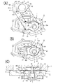
以下、本発明の実施形態を図面に基づいて説明する。本発明は、図1に示すように、主にポンプボディAと、流路仕切板4と、インペラ軸部5と、インペラ6とから構成される。前記流路仕切板4,インペラ6及びインペラ軸部5が組み付けられたポンプボディAが、自動車のエンジン本体7の所定位置に装着される。ポンプボディAは、アルミ合金製であり、エンジン本体7とは互いに対向して組み合わされて接合されウォーターポンプが構成される〔図1(C)参照〕。
Hereinafter, embodiments of the present invention will be described with reference to the drawings. As shown in FIG. 1, the present invention mainly includes a pump body A, a flow
そして、ポンプボディAがエンジン本体7の被装着箇所に接合されることにより、ポンプボディAとエンジン本体7との間に冷却水流路が構成される。ポンプボディAは、図1(A),図2(A),(B)に示すように、ボディ本体部1と吸入側流路2とから構成され、ボディ本体部1の内方側は開放された側面であり、接合面11と、前記吸入側流路2が形成されている〔図1(A),図2(A),(B)参照〕。前記接合面11は、ポンプボディAをエンジン本体7に接合する部位であり平坦面に形成されている。
The pump body A is joined to the mounting position of the
前記冷却水流路は、流路仕切板4によって、吸入側流路2と吐出側流路8とに仕切られる。エンジン本体7側のポンプボディAを装着するための被装着箇所は、例えばギヤケース等、冷却水流路が必要な箇所が適宜選択されるものである。ポンプボディAに形成されている吸入側流路2は、主に円形窪み部21、方形窪み部22から構成されている。前記円形窪み部21には、貫通孔部3が一体形成されており、該貫通孔部3は、貫通孔であって、インペラ軸部5の軸受部51が圧入固定される部位である〔図1(C)参照〕。
The cooling water flow path is divided into a suction
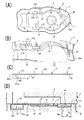
前記流路仕切板4は、図2(C)に示すように、金属製または合成樹脂製の薄板状もしくは平板状であり、長手方向に沿って先端部43,吸入仕切部41,固定シール部42の順番で形成されており、具体的には前記吸入仕切部41を中心としてその一方側に固定シール部42が形成され、前記吸入仕切部41の他方側、すなわち固定シール部42の形成位置とは反対側となる位置に先端部43が形成される。また、流路仕切板4の長手方向に直交する方向を幅方向とする。
As shown in FIG. 2C, the flow
流路仕切板4は、ポンプボディAの吸入側流路2の開口箇所に装着された状態で、エンジン本体7側に接合した場合に、エンジン本体7に対向する側を表面4fとし、吸入側流路2側に対向する面を裏面4rとする〔図1(C),図2(C)参照〕。吸入仕切部41は、円形板片41aの直径中心を中心として円形の軸挿通孔41bが形成され、該軸挿通孔41bには、インペラ軸部5のインペラ軸52が挿通する。また、軸挿通孔41bは、冷却水が吸入側流路2から吐出側流路8へ流れる流路としての役目もなしている。
When the flow
前記固定シール部42は、シール板片421と、固定延設部422,422とから構成されたものである。シール板片421は、長方形又は正方形等の方形状且つ平坦状に形成されており、ポンプボディAがエンジン本体7に装着されると、シール板片421の長手方向における外端縁421aがエンジン本体7に接し、吸入側流路2と吐出側流路8とに仕切られる。両固定延設部422,422は、前記シール板片421に対して裏面4r側に向かって折曲形成されたものである。該固定延設部422は、固定シール部42の幅方向両端辺の長手方向において略半分程度の長さに亘って形成されたものであり、該固定シール部42の前記吸入仕切部41と隣接する部位に対して長手方向の反対側となる領域に形成されたものである。
The fixed
両固定延設部422,422は、シール板片421に対して傾斜又は直角に形成される。また、両固定延設部422,422は、幅方向において略左右対称に延設され、同等長さ,同等幅,同等角度に傾斜する。先端部43は、図1(A)に示すように、吸入仕切部
41側の位置から長手方向外方に向かうに従い次第に幅が狭くなる略三角形状に形成された板片部であり、流路仕切板4の表面4f側に突出する突起部44がプレス成形もしくは樹脂成形により形成されている。該突起部44は、ポンプボディAがエンジン本体7へ接合されたときに、エンジン本体7の被装着箇所における被接合面から押圧される被押圧部としての役割をなすものである。
Both fixed extending
前記吸入側流路2において、前記円形窪み部21の外周縁に収納段差部25が形成され、前記円形窪み部21の周縁より外方に向かって突出するように先端段差部28が形成されている。該先端段差部28は、全面が浅い平坦な底面28aを有する窪みである。方形
窪み部22箇所で旦つ前記円形窪み部21側寄りの位置には、連結段差部26が形成され、該連結段差部26に隣接して挿入段差部27が形成される。前記連結段差部26は、前記収納段差部25と前記挿入段差部27を連結している。前記収納段差部25は、円形窪み部21の幅方向両側に形成され、連結段差部26及び挿入段差部27は、方形窪み部22の幅方向両側に形成されている。
In the suction-
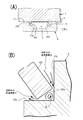
前記挿入段差部27の深さは、連結段差部26の深さよりも深く形成される。また、前記挿入段差部27の底面の幅は、連結段差部26の底面の幅よりも広く形成される。また、先端段差部28の深さは、流路仕切板4の板厚と突起部44の高さとを合わせた寸法に略近いものであり、先端部43と突起部44とが共に先端段差部28内に収まる深さである。前記挿入段差部27は、流路仕切板4の固定延設部422が挿入されて、収まる部位であり、その深さは流路仕切板4に形成された固定延設部422が十分に収まる程度の深さ寸法を有している〔図1(B),図3(A)参照〕。また、前記流路仕切板4が、吸入側流路2の開口に適正に装着された状態で、前記固定延設部422,422の先端である終端縁422aは、挿入段差部27に近接するが接触はしない構成である(図3参照)。
The insertion stepped
前記収納段差部25に流路仕切板4の吸入仕切部41の外周が対応し、連結段差部26に固定シール部42の吸入仕切部寄りの幅方向端縁が対応し、挿入段差部27に固定延設部422が対応し、先端段差部28に先端部43が対応するようにして、前記流路仕切板4が吸入側流路2の開口に配置される。そして、前記ポンプボディAの貫通孔部3には、インペラ軸部5の軸受部51が装着されており、インペラ軸52は、前記流路仕切板4の軸挿通孔41bを挿通し、流路仕切板4の表面側に突出する状態となっている〔図1(C),図2(D)参照〕。
The outer periphery of the
インペラ軸52にインペラ6が圧入等の手段により装着される。該インペラ6の外径は、流路仕切板4の軸挿通孔41bの直径よりも大きく形成されている。インペラ6がボンプポディAに適正に装着された状態において、インペラ6の羽根61の下端6tと流路仕切板4の吸入仕切部41が近接しているので、輸送時や組み付け時に流路仕切板4がボンプボディAから脱落することを防止している。また、流路仕切板4の固定シール部42に形成された両固定延設部422,422がポンプポディAに形成された両挿入段差部27,27に挿入されることにより、両固定延設部422,422が両挿入段差部27,27
に引っ掛かり、輸送時や組み付け時に固定シール部42がポンプポディAからズレることを防止できる。
The impeller 6 is mounted on the
It is possible to prevent the fixed
このように、流路仕切板4がポンプボディAの吸入側流路2の開口に組み付けられる構成では、両固定延設部422,422が両挿入段差部27,27に挿入されることにより、流路仕切板4をポンプボディAから外れ難い構成にすることができる〔図3(A)参照〕。実際の組み付け時において、ポンプボディAを、エンジン本体7の被装着箇所に接合することにより、流路仕切板4の先端部43に形成された突起部44がエンジン本体7側の被接合面71によって押圧され、流路仕切板4の先端部43が吸入側流路2の先端段差部28内に押し込まれて沈み込む状態となる。そして、流路仕切板4は先端部43側が先
端段差部28内に埋まり込むようにして傾斜しようとする。
Thus, in the configuration in which the flow
流路仕切板4の先端部43が先端段差部28内に埋まるように傾斜することで、固定シール部42の端部箇所が接合面11から突出する状態となるが、ポンプボディAをエンジン本体7側被装着箇所の被接合面71に接合することで、該被接合面71に前記固定シール部42が押圧され、シール板片421の外端縁421aがギヤケースに接し、吸入側流路2と吐出側流路8とが仕切られる。流路仕切板4は吸入側流路2の開口箇所に向かって押圧され、強固に固定される。
By inclining the
ポンプボディAをエンジン本体7側に接合することによって、固定された流路仕切板4の両固定延設部422の終端縁422aと、ポンプボディAの挿入段差部27と挿入底面27aと挿入側壁面27bとがなす隅角箇所には略三角形状の空隙部Qが形成される(図3参照)。該空隙部Qは、吐出側流路8の正圧と、ポンプボディA側の吸入側流路2の負圧の中間程度の圧力が発生する空間となる。また、前記空隙部Qは、吐出側流路8から最も離間しているので、水圧がある程度減衰し圧力が低くなる箇所である。吐出側流路8からの高い圧力の冷却水は圧力の低い吸入側流路2に逆流しようとするが、冷却水が吐出側流路8から吸入側流路2に向かって逆流する事態が生じた場合には、前記空隙部Qによって逆流する冷却水の圧力を下げるように作用する。
By joining the pump body A to the
さらにまた、前記空隙部Qでは、逆流した冷却水の流れを乱れさせ、冷却水の逆流の流速を低下させる役目もなす〔図3(B)参照〕。その後、冷却水が吐出側流路8から吸入側流路2へ逆流しようとしても、空隙部Qは通路が狭いため吸入側流路2へ逆流しにくい構成となる。また吐出側流路8より前記三角形状の空隙部Qに冷却水が逆流した段階で前述したように圧力が下がっており、これにより空隙部Qと吸入側流路2の圧力差は少なくなっているため、冷却水の逆流の流速は低下する。このように、空隙部Qは圧力緩衝空間としての機能を果たし、吸入側流路2への逆流を抑制することができるため、ポンプ吐出性能が向上する。
Furthermore, the gap Q also serves to disturb the flow of the cooling water that has flown backward and to reduce the flow velocity of the reverse flow of the cooling water (see FIG. 3B). After that, even if the cooling water tries to flow backward from the discharge
A…ポンプボディ、11…接合面、2…吸入側流路、25…収納段差部、
26…連結段差部、27…挿入段差部、27a…挿入底面、27b…挿入側壁面、
28…先端段差部、4…流路仕切板、41…吸入仕切部、42…固定シール部、
422…固定延設部、43…先端部、44…突起部、7…エンジン本体。
A ... pump body, 11 ... joint surface, 2 ... suction side flow path, 25 ... storage step,
26 ... Connection step part, 27 ... Insert step part, 27a ... Insert bottom surface, 27b ... Insert side wall surface,
28 ... tip step part, 4 ... flow path partition plate, 41 ... suction partition part, 42 ... fixed seal part,
422 ... Fixed extension part, 43 ... Tip part, 44 ... Projection part, 7 ... Engine main body.
Claims (3)
Priority Applications (1)
| Application Number | Priority Date | Filing Date | Title |
|---|---|---|---|
| JP2010090940A JP2011220249A (en) | 2010-04-09 | 2010-04-09 | Water pump |
Applications Claiming Priority (1)
| Application Number | Priority Date | Filing Date | Title |
|---|---|---|---|
| JP2010090940A JP2011220249A (en) | 2010-04-09 | 2010-04-09 | Water pump |
Publications (1)
| Publication Number | Publication Date |
|---|---|
| JP2011220249A true JP2011220249A (en) | 2011-11-04 |
Family
ID=45037531
Family Applications (1)
| Application Number | Title | Priority Date | Filing Date |
|---|---|---|---|
| JP2010090940A Pending JP2011220249A (en) | 2010-04-09 | 2010-04-09 | Water pump |
Country Status (1)
| Country | Link |
|---|---|
| JP (1) | JP2011220249A (en) |
Cited By (1)
| Publication number | Priority date | Publication date | Assignee | Title |
|---|---|---|---|---|
| CN110285078A (en) * | 2019-07-23 | 2019-09-27 | 浙江耀达智能科技股份有限公司 | A kind of water pump controller |
-
2010
- 2010-04-09 JP JP2010090940A patent/JP2011220249A/en active Pending
Cited By (1)
| Publication number | Priority date | Publication date | Assignee | Title |
|---|---|---|---|---|
| CN110285078A (en) * | 2019-07-23 | 2019-09-27 | 浙江耀达智能科技股份有限公司 | A kind of water pump controller |
Similar Documents
| Publication | Publication Date | Title |
|---|---|---|
| JP5526096B2 (en) | Electronic controller seal structure | |
| US20190329640A1 (en) | Vibration prevention device | |
| CN104024685A (en) | Anti-vibration device | |
| CN205014747U (en) | Refrigerator door body and refrigerator | |
| JP2012064364A (en) | Connector | |
| JP2014151678A (en) | Coupling structure and bumper cover structure of resin component | |
| US20170112004A1 (en) | Electronic control device | |
| JP5609779B2 (en) | Electronic control unit | |
| JPWO2004051113A1 (en) | Liquid-filled vibration isolator | |
| JP2011220249A (en) | Water pump | |
| JP2004179280A (en) | Case for controlling | |
| JP2008190429A (en) | Fuel pump module | |
| JP2006029244A (en) | Fuel tank unit | |
| KR20040009068A (en) | Mounting structure of vehicle's upper radiator | |
| KR102578926B1 (en) | drain pump | |
| CN216331371U (en) | Trim subassembly and car | |
| JP5302069B2 (en) | Oil pan | |
| CN113674726A (en) | Buzzer device | |
| CN114056078B (en) | Mounting bracket, water pump and vehicle | |
| JP6381607B2 (en) | Electronic control unit | |
| JP5659105B2 (en) | Support structure for headlamp cover | |
| CN100529350C (en) | Flange structure | |
| CN114341509B (en) | Fastener | |
| CN110185658B (en) | Fan frame with shock-absorbing function | |
| JP4570518B2 (en) | Resin pump |