JP2011186971A - Printer system - Google Patents
Printer system Download PDFInfo
- Publication number
- JP2011186971A JP2011186971A JP2010053956A JP2010053956A JP2011186971A JP 2011186971 A JP2011186971 A JP 2011186971A JP 2010053956 A JP2010053956 A JP 2010053956A JP 2010053956 A JP2010053956 A JP 2010053956A JP 2011186971 A JP2011186971 A JP 2011186971A
- Authority
- JP
- Japan
- Prior art keywords
- thermal transfer
- printer
- ink sheet
- correction control
- image data
- Prior art date
- Legal status (The legal status is an assumption and is not a legal conclusion. Google has not performed a legal analysis and makes no representation as to the accuracy of the status listed.)
- Pending
Links
Images


Abstract
Description
本発明はプリンターシステムに関し、特に熱転写型プリンターに関し、印刷メディアの発色特性の経時変化や生産ロット違いに起因する発色特性のばらつきを抑制するためのプリンターシステムに関する。 The present invention relates to a printer system, and more particularly to a thermal transfer printer, and more particularly to a printer system for suppressing variations in color development characteristics due to changes in color development characteristics of print media and production lot differences.
熱転写(昇華)型プリンターは、インクシートと専用のペーパー(印画紙)を使用し、ディジタルカメラ等で撮影したディジタル写真などの画像データを、銀塩写真のように高精細な画質で印刷する用途で、証明写真ブースやセルフプリント端末、参照用の医用画像印刷機等に広く使用されている。 Thermal transfer (sublimation) printers use ink sheets and special paper (printing paper) to print image data such as digital photographs taken with a digital camera, etc. with high-definition image quality like silver halide photographs. Therefore, it is widely used in ID photo booths, self-printing terminals, reference medical image printing machines, and the like.
しかし熱転写型プリンターは、熱転写型プリンター周辺の温度や湿度、インクシートの生産時からの経時変化、インクシートの生産ロットの違い等の影響で印刷メディアの発色感度が変化し発色特性ばらつきが生じるため、それらの違いに応じて、サーマルヘッドに対する熱制御の補正を行う必要がある。 However, in thermal transfer printers, the color sensitivity of the print media changes due to the temperature and humidity around the thermal transfer printer, changes over time from the production of the ink sheet, and differences in the production lot of the ink sheet. Therefore, it is necessary to correct the thermal control for the thermal head according to the difference between them.
熱転写型プリンター周辺の温度、湿度の違いに関しては、例えば印刷時のサーマルヘッドの温度や庫内の温度・湿度をサーミスタ・湿度センサ等を用いて計測し、熱転写型プリンターに備えられるフラッシュメモリに格納されたサーマルヘッドの熱制御の補正制御テーブルを参照して、温度・湿度に応じた補正値を決定し、その補正値に基づいた制御を、サーマルヘッドコントローラを介してサーマルヘッドに行うことにより、サーマルヘッドに印加されるエネルギーを適切に制御することができる。 Regarding the difference in temperature and humidity around the thermal transfer printer, for example, the temperature of the thermal head during printing and the temperature / humidity inside the cabinet are measured using a thermistor, humidity sensor, etc., and stored in the flash memory provided in the thermal transfer printer. By referring to the correction control table for the thermal control of the thermal head, the correction value according to the temperature and humidity is determined, and control based on the correction value is performed on the thermal head via the thermal head controller, The energy applied to the thermal head can be appropriately controlled.
このように従来は、印刷時の環境から受ける影響を補正するために、熱転写型プリンターのフラッシュメモリに格納されている熱制御の補正制御テーブルを参照することにより、サーマルヘッドに対し制御を行っていた。補正制御テーブルは、熱転写型プリンター特有の制御パラメータであるため、熱転写型プリンター内のメモリに格納されているのが一般的であり、当該補正制御テーブルの変更を可能とするためには、システムが複雑になる等の問題があった。 Thus, conventionally, in order to correct the influence from the environment during printing, the thermal head is controlled by referring to the thermal control correction control table stored in the flash memory of the thermal transfer printer. It was. Since the correction control table is a control parameter specific to the thermal transfer printer, it is generally stored in the memory in the thermal transfer printer. In order to enable the correction control table to be changed, the system must There were problems such as complexity.
また、環境、経時変化、生産ロットの違いによる印刷メディアの発色特性ばらつきに対する補正は、例えば特許文献1では、内蔵するディジタルカメラでテストパターンを撮像し、印刷されたテストチャートを測色してキャリブレーションを行い、発色補正量を求めるという手法が提案されているが、測色機などの装置が必要であり、コスト増やシステム構造の複雑化等の問題があった。 In addition, for example, in Japanese Patent Application Laid-Open No. 2004-86400, correction of variations in color development characteristics of print media due to differences in environment, changes with time, and production lots is performed by capturing a test pattern with a built-in digital camera and measuring the printed test chart for calibration. Although a method has been proposed in which a color correction amount is obtained by performing a calibration, a device such as a colorimeter is required, which causes problems such as an increase in cost and a complicated system structure.
本発明は、上記のような問題が解決するためになされたものであり、構成が複雑化等することなく、印刷メディアの発色特性ばらつきを補正可能、かつその補正量を変更可能なプリンターシステムを提供することを目的とする。 The present invention has been made to solve the above problems, and provides a printer system capable of correcting variations in color development characteristics of a print medium and changing the correction amount without complicating the configuration. The purpose is to provide.
本発明にかかるプリンターシステムは、画像データに基づきサーマルヘッドを駆動し、インクシートを加熱することにより印画を行う熱転写型プリンターと、前記熱転写型プリンターと通信可能な外部機器とを備え、前記外部機器は、前記インクシートの所定の特性に応じて、前記画像データに基づく前記サーマルヘッドの駆動を補正する補正制御データを前記熱転写型プリンターに送信する。 A printer system according to the present invention includes a thermal transfer type printer that performs printing by driving a thermal head based on image data and heating an ink sheet, and an external device that can communicate with the thermal transfer type printer. Transmits correction control data for correcting the driving of the thermal head based on the image data to the thermal transfer printer in accordance with predetermined characteristics of the ink sheet.
本発明にかかるプリンターシステムによれば、画像データに基づきサーマルヘッドを駆動し、インクシートを加熱することにより印画を行う熱転写型プリンターと、前記熱転写型プリンターと通信可能な外部機器とを備え、前記外部機器は、前記インクシートの所定の特性に応じて、前記画像データに基づく前記サーマルヘッドの駆動を補正する補正制御データを前記熱転写型プリンターに送信することにより、システム構成を複雑化することなく、印刷メディアの発色特性ばらつきを補正可能、かつその補正量を変更可能となる。 According to the printer system of the present invention, a thermal transfer printer that performs printing by driving a thermal head based on image data and heating an ink sheet, and an external device that can communicate with the thermal transfer printer, The external device transmits correction control data for correcting the driving of the thermal head based on the image data to the thermal transfer printer according to the predetermined characteristics of the ink sheet, without complicating the system configuration. Therefore, it is possible to correct the color development characteristic variation of the print medium and change the correction amount.
<A.実施の形態1>
以下、本発明の実施の形態1について図1〜4を参照して説明する。なお、本発明は以下の例に限定されるものではなく、本発明の要旨を逸脱しない範囲で任意に変更可能であることは言うまでもない。
<A.
<A−1.構成>
図1は、本発明にかかるプリンターシステムの構成を示す概念図である。図1に示すように、プリンターシステムは、外部機器であるホストPC1と、熱転写型プリンター3とが、USB2を介して接続され、互いに通信可能となっている。
<A-1. Configuration>
FIG. 1 is a conceptual diagram showing the configuration of a printer system according to the present invention. As shown in FIG. 1, in the printer system, a
熱転写型プリンター3は、USB2で接続されるUSBコントローラ4と、USBコントローラ4と制御バス100を介して接続される、CPU6、画像メモリコントローラ9、サーマルヘッドコントローラ11、タグコントローラ13と、CPU6に測定データを出力するサーミスタ7および湿度センサ8と、画像メモリコントローラ9に制御される画像メモリ10と、サーマルヘッドコントローラ11に制御されるサーマルヘッド12と、タグコントローラ13と接続されるアンテナ14とを備える。
The thermal
<A−2.動作>
画像印刷時、ホストPC1からUSB2ケーブルを介して、印刷するためのRGB各色8ビット(256階調)の画像データを熱転写型プリンター3に転送し、画像メモリ10にその画像データを格納する。そして、その画像データに対応した熱エネルギー量を、画像メモリ10に格納された変換テーブルからCPU6が参照し、サーマルヘッドコントローラ11に対し、CPU6がサーマルヘッド12に対する適切な印加エネルギー値を設定することにより、画像データに呼応した発色特性でインクシートを加熱し、印画を行う。
<A-2. Operation>
At the time of image printing, image data of 8 bits for each RGB color (256 gradations) for printing is transferred from the
熱転写型プリンター3における熱制御は、入力される画像データの分解能よりも高い分解能を持つ階調で制御される場合が多く、例えば入力画像データが8ビット(256階調)に対し、16ビット(65536階調)のような高い分解能で制御される。
Thermal control in the
ここで、熱転写型プリンターでは、印刷メディアの発色特性ばらつきを考慮して、上記の熱制御を補正する必要がある。図2は、ある一定エネルギーをサーマルヘッドから印刷メディアとしてのインクシートに与えたときの、インクシートの小巻後の時間経過に伴う、印刷濃度の変化を模式的に示した図である。図2の縦軸が印刷濃度、横軸がインクシートをインクリボンに巻いてからの時間経過を示している。 Here, in the thermal transfer type printer, it is necessary to correct the thermal control described above in consideration of variations in color development characteristics of print media. FIG. 2 is a diagram schematically showing a change in print density with the passage of time after a small volume of the ink sheet when a certain amount of energy is applied from the thermal head to the ink sheet as the print medium. In FIG. 2, the vertical axis represents the print density, and the horizontal axis represents the time elapsed since the ink sheet was wound on the ink ribbon.
図2によれば、インクシートの製造過程で、各インクリボンにインクシートが小巻にされた時点から印刷濃度が低下し、3〜6ヵ月後程度で安定域に収束することが分かる。この3〜6ヵ月間の印刷濃度の変化を経時ばらつきと呼ぶ。 According to FIG. 2, it can be seen that, in the process of manufacturing the ink sheet, the printing density decreases from the time when the ink sheet is rolled up on each ink ribbon, and converges to the stable region after about 3 to 6 months. This change in print density over 3 to 6 months is referred to as aging variation.
また、異なるロットA、B、C間での印刷濃度の推移が異なっており、安定域においても収束値が異なる。これらは各インクシートの生産ロットの違いによるものであり、この印刷濃度差のことをロットばらつきと呼ぶ。 In addition, the transition of the print density between different lots A, B, and C is different, and the convergence value is also different in the stable region. These are due to the difference in production lot of each ink sheet, and this printing density difference is called lot variation.
また、熱転写型プリンターでは、白色からの画像のつながりを滑らかにするために、図3に示すように、ヘッド印加エネルギーに余熱制御領域を設定し、画像データが0階調(白色)では発色せずに、1階調で直ちに発色するような余熱をサーマルヘッドに与えている。図3の横軸は入力階調データを示し、縦軸はサーマルヘッドの印加エネルギーを示している。この余熱制御領域は、温度、湿度等の環境変化に対応してなされる補正領域に対応する。 In addition, in a thermal transfer printer, in order to smooth the connection of images from white, as shown in FIG. 3, a residual heat control area is set in the head applied energy, and color development occurs when the image data is 0 gradation (white). Instead, the thermal head is given a residual heat that immediately develops color in one gradation. In FIG. 3, the horizontal axis represents input gradation data, and the vertical axis represents energy applied to the thermal head. This residual heat control area corresponds to a correction area made in response to environmental changes such as temperature and humidity.
図3によると、印刷時の温度や湿度の影響による発色特性の変化(環境ばらつき)を補正するため、インクシートの発色点以下の印加エネルギー範囲に環境ばらつき補正領域を設定し、印刷時環境に応じて最適なエネルギーを印加するようサーマルヘッド12の余熱制御を行っていることがわかる。
According to FIG. 3, in order to correct the change in color development characteristics (environmental variation) due to the influence of temperature and humidity during printing, an environment variation correction area is set in the applied energy range below the color development point of the ink sheet. It can be seen that the residual heat control of the
図4は、図3の発色点付近の拡大図であり、発色特性ばらつきのあるインクシートでは、発色点でのヘッド印加エネルギーが異なることを模式的に示した図である。 FIG. 4 is an enlarged view in the vicinity of the coloring point in FIG. 3, and is a diagram schematically showing that the head application energy at the coloring point is different in an ink sheet having coloring characteristic variation.
図4によると、サーマルヘッドの印加エネルギーは、本来画像データの0階調目と1階調目との間でインクシートが発色点に達するように変換テーブルを参照して制御されるが、前述のようにインクシートの経時変化や生産ロットの違い等によって発色特性ばらつきが生じるため、例えば、発色感度が最も高いインクシートの発色点1と、発色感度が最も低いインクシートの発色点2との間には、図に示すような発色点ばらつき範囲が存在する。
According to FIG. 4, the applied energy of the thermal head is controlled with reference to the conversion table so that the ink sheet reaches the coloring point between the 0th gradation and the 1st gradation of the image data. As described above, the color development characteristics vary due to changes in the ink sheet over time, production lot differences, and the like. For example, the
熱転写型プリンターにおいては、0階調(白色)における発色点のばらつきが発生した場合、発色感度が高いインクシートでは本来白色であるべき印刷部分に色が付き(例えば発色点1の場合)、また発色感度が低いインクシートでは本来白飛びしていない画像領域が白色にプリントされてしまう(例えば発色点2の場合)。 In the thermal transfer type printer, when the variation of the coloring point in 0 gradation (white) occurs, the ink sheet having a high coloring sensitivity is colored on the printing portion that should be white (for example, in the case of the coloring point 1). In an ink sheet having a low color development sensitivity, an image area that is not originally overprinted is printed in white (for example, in the case of a color development point 2).
前述のような発色点に限らず、図2に示したような経時変化や生産ロットの違いによる発色特性ばらつきによっても印刷濃度はばらつくが、特に図3、4のように発色点がばらついた場合の影響が、視覚的良く目立つことが一般的に知られている。 Not only the color spots as described above, but also the print density varies due to variations in color development characteristics due to changes over time and production lots as shown in FIG. 2, but particularly when the color spots vary as shown in FIGS. It is generally known that the effects of are conspicuous visually.
本発明にかかるプリンターシステムでは、上記のような印刷メディアの発色特性ばらつきを補正するための補正制御を、ホストPC1から熱転写型プリンター3に送信される補正制御データを用いて行う。
In the printer system according to the present invention, the correction control for correcting the color characteristic variation of the print medium as described above is performed using the correction control data transmitted from the
本発明にかかるプリンターシステムでは、画像データをホストPC1から熱転写型プリンター3に転送する際、熱転写型プリンター3内部のガンマテーブルの微調整のための補正制御データとして、経時ばらつき、ロットばらつき、環境ばらつき等による印刷メディアの発色特性ばらつきに対する補正情報を外部機器であるホストPC1から転送することで、熱転写型プリンター3におけるサーマルヘッド12の印加エネルギーの熱制御を、外部から補正することが可能である。
In the printer system according to the present invention, when image data is transferred from the
補正情報としては、インクシートの特性としての温度・湿度特性について、例えば熱転写型プリンター3に備えられた測定手段としてのサーミスタ7、湿度センサ8において取得された温度・湿度の測定値をホストPC1に送信し、送信されたこれらの測定値に応じて作成される補正情報がある。当該補正情報の作成のため、ホストPC1には、温度・湿度の測定値に応じた補正情報を作成可能な補正制御テーブルが備えられる。
As the correction information, with respect to the temperature / humidity characteristics as the characteristics of the ink sheet, for example, the temperature / humidity measurement values acquired by the thermistor 7 and the humidity sensor 8 as the measuring means provided in the thermal
作成された補正情報は熱転写型プリンター3に送信され、この情報に基づいて、CPU6が環境ばらつき分を補正する制御を、サーマルヘッドコントローラ11を介してサーマルヘッド12に行う。サーマルヘッド12に印加されるエネルギーを適切に制御することで、階調補正を行い画像を適切に印刷できる。
The created correction information is transmitted to the thermal
<A−3.効果>
本発明にかかる実施の形態1によれば、プリンターシステムにおいて、画像データに基づきサーマルヘッド12を駆動し、インクシートを加熱することにより印画を行う熱転写型プリンター3と、熱転写型プリンター3と通信可能な外部機器であるホストPC1とを備え、ホストPC1は、インクシートの所定の特性に応じて、画像データに基づくサーマルヘッド12の駆動を補正する補正制御データを熱転写型プリンター3に送信することで、システム構成を複雑化することなく、印刷メディアの発色特性ばらつきを補正可能、かつその補正量を変更可能となる。インクシートごとに発色点がばらついても、その補正制御データは外部から送信されるので、ユーザが補正制御することができ、かつ簡便にその補正の変更も容易である。
<A-3. Effect>
According to the first embodiment of the present invention, in the printer system, the
また、補正制御テーブルが膨大となる場合、熱転写型プリンター3内に備える場合には容量に限界があるが、ホストPC1を用いる場合にはそのような問題を回避することができる。
Further, when the correction control table is enormous, the capacity is limited when it is provided in the
また、本発明にかかる実施の形態1によれば、プリンターシステムにおいて、インクシートの所定の特性は、温度・湿度特性であり、熱転写型プリンター3は、熱転写型プリンター3周辺の温度・湿度を測定する測定手段としてのサーミスタ7、湿度センサ8をさらに備え、熱転写型プリンター3は、温度・湿度の値を、外部機器であるホストPC1に送信し、ホストPC1は、受信した温度・湿度の値に応じて、補正制御データを作成する補正制御テーブルをさらに備えることで、温度・湿度の測定値に応じた補正情報を補正制御テーブルに基づいて生成し、熱転写型プリンター3に送信することができ、環境ばらつきを抑制する適切な補正をサーマルヘッド12に行うことができる。
According to the first embodiment of the present invention, in the printer system, the predetermined characteristics of the ink sheet are temperature / humidity characteristics, and the
<B.実施の形態2>
<B−1.補正制御データの転送>
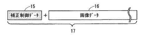
図5は、実施の形態1におけるプリンターシステムにおいて、ホストPC1から熱転写型プリンター3へ転送される転送データ17の一例を模式的に示したものである。転送データ17は、画像データ16に加えて、その先頭に補正制御データ15が付加されて、ホストPC1から順次転送される。
<B. Second Embodiment>
<B-1. Transfer of correction control data>
FIG. 5 schematically shows an example of
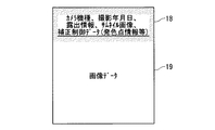
図6では、画像データに補正制御データをヘッダー18として埋め込み、画像データ19と合わせた1つのファイルとして、ホストPC1から熱転写型プリンター3に転送される場合を示している。図6に示されるように、画像データ19に付加情報を埋め込み可能なファイル形式、例えばEXIF形式の画像ファイルにおいて、画像データ19のヘッダー18中に、カメラ機種、撮影年月日、露出情報、サムネイル画像等とともにホストPC1からの補正情報を格納することで、外部機器であるホストPC1から熱転写型プリンター3を制御できる。
FIG. 6 shows a case where correction control data is embedded in the image data as a
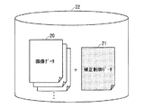
また、図7のように、画像データ20のファイルに付随した補正制御データのファイル形式、例えばDPOF形式のヘッダーファイル形態では、画像データ20を転送する際に補正制御データ21のファイルを同時に転送することで、熱転写型プリンター3の制御を行うことが可能である。この方法は、メモリーカード等のリムーバブルディスク22中の画像データ20のファイルをセルフプリント端末で印刷する場合における、ユーザによるプリンター制御等に応用できる。
Further, as shown in FIG. 7, in the file format of the correction control data attached to the file of the
<B−2.効果>
本発明にかかる実施の形態2によれば、プリンターシステムにおいて、補正制御データは、外部機器であるホストPC1から熱転写型プリンター3へ送信される画像データに連続して、順次送信されることで、画像データとともに補正制御データを熱転写型プリンター3に送信し、ホストPC1からの熱転写型プリンター3の制御が実現できる。
<B-2. Effect>
According to the second embodiment of the present invention, in the printer system, the correction control data is sequentially transmitted in succession to the image data transmitted from the
また、本発明にかかる実施の形態2によれば、プリンターシステムにおいて、補正制御データは、外部機器であるホストPC1から熱転写型プリンター3へ送信される画像データのヘッダー中に格納されて送信されることで、画像データとともに補正制御データを熱転写型プリンター3に送信し、ホストPC1からの熱転写型プリンター3の制御が実現できる。
Further, according to the second embodiment of the present invention, in the printer system, the correction control data is stored and transmitted in the header of the image data transmitted from the
<C.実施の形態3>
<C−1.動作>
本発明の実施の形態3によるプリンターシステムの構成は、本発明の実施の形態1によるプリンターシステムの構成と同様であるが、図1におけるタグコントローラ13とアンテナ14は、熱転写型プリンター3に装着されたインクシート(図示せず)の製造年月日や生産ロット等の個体情報を取得し、USB2のケーブルを介してホストPC1にその情報を送信することが可能である。タグコントローラ13とアンテナ14は、熱転写型プリンター3に装着されているインクシートに付随しているタグからインクシートの個別情報を読み取る読み取り手段である。
<
<C-1. Operation>
The configuration of the printer system according to the third embodiment of the present invention is the same as the configuration of the printer system according to the first embodiment of the present invention, but the
一般的に熱転写型プリンター3は内部に時計機能を持たないことが多いが、インクシートの製造年月日をホストPC1に転送することができれば、ホストPC1が把握する現在の時刻と製造年月日との差異により、経時変化量を推定することが可能になる。このとき、ホストPC1に備えられた補正制御テーブルにおいて、インクシートの製造年月日の情報に応じて補正制御データを作成し、これをもとに発色特性ばらつきの詳細な制御に活用できる。
In general, the
なお、製造時から時間が経過するほど、インクシートの発色特性は感度が低下することが一般的に知られており、また高温環境下で保管されたインクシートは経時変化での感度低下がより加速されるため、サーマルヘッドにより大きなエネルギーを付加する等の制御を要する。 It is generally known that the sensitivity of the color development characteristics of the ink sheet decreases as time elapses from the time of manufacture, and the sensitivity of the ink sheet stored in a high temperature environment decreases with time. Since it is accelerated, control such as adding a large energy to the thermal head is required.
また、インクシートの生産ロットの情報をホストPC1に転送することにより、ホストPC1からサーマルヘッド12へ、ロットばらつきに対する適切な補正制御を行うことができる。このとき、ホストPC1に備えられた補正制御テーブルにおいて、インクシートの生産ロットの情報に応じて作成した補正制御データが用いられる。
Further, by transferring the information on the production lot of the ink sheet to the
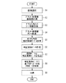
以下、本発明の実施の形態3によるプリンターシステムの処理手順の一例を図8のフローチャートを用いて説明する。 Hereinafter, an example of the processing procedure of the printer system according to the third embodiment of the present invention will be described with reference to the flowchart of FIG.
ホストPC1上で、ユーザが印刷したい画像を選択し(ステップS1)、熱転写型プリンター3側ではサーミスタ7と湿度センサ8により、サーマルヘッド12や熱転写型プリンター3内部の温度と湿度の計測を行う(ステップS2)。
The user selects an image to be printed on the host PC 1 (step S1), and the temperature and humidity inside the
また、タグコントローラ13とアンテナ14により、インクシートの製造年月日や生産ロット等の個体情報の取得が行われ(ステップS3)、USB2のケーブルを介して、ホストPC1に熱転写型プリンター3側の情報を転送する(ステップS4)。
The
ホストPC1では、熱転写型プリンター3から転送された熱転写型プリンター3の温度・湿度の測定値、インクシートの個体データといった情報をもとに、ホストPC1内に保持する補正制御テーブルを参照して(ステップS5)補正制御データを作成し(ステップS6)、補正制御データと画像データとを熱転写型プリンター3に転送する(ステップS7)。
The
熱転写型プリンター3では、転送された補正制御データに基づいてサーマルヘッドコントローラ11を制御し、サーマルヘッド12に適切な印加エネルギーを印加する(ステップS8)。これによって発色特性ばらつきに対する補正制御を行い、インクシートごとの発色特性に応じた印刷を行うことができる(ステップS9)。
The thermal
<C−2.効果>
本発明にかかる実施の形態3によれば、プリンターシステムにおいて、インクシートの所定の特性は、経時変化特性および/又は生産ロット特性をさらに含み、熱転写型プリンター3は、インクシートの、製造年月日および/又は生産ロットの情報を読み取る、読み取り手段であるタグコントローラ13、アンテナ14をさらに備え、熱転写型プリンター3は、インクシートの製造年月日および/又は生産ロットの情報を、外部機器であるホストPC1に送信し、ホストPC1における補正制御テーブルは、受信したインクシートの製造年月日および/又は生産ロットの情報にも応じて、補正制御データを作成することで、経時ばらつき、ロットばらつきにも対応した適切な補正制御を、熱転写型プリンター3におけるサーマルヘッド12に行うことができる。
<C-2. Effect>
According to the third embodiment of the present invention, in the printer system, the predetermined characteristic of the ink sheet further includes a time-varying characteristic and / or a production lot characteristic, and the
1 ホストPC、2 USB、3 熱転写型プリンター、4 USBコントローラ、6 CPU、7 サーミスタ、8 湿度センサ、9 画像メモリコントローラ、10 画像メモリ、11 サーマルヘッドコントローラ、12 サーマルヘッド、13 タグコントローラ、14 アンテナ、15,21 補正制御データ、16,19,20 画像データ、17 転送データ、18 ヘッダー、22 リムーバブルディスク、100 制御バス。 1 Host PC, 2 USB, 3 Thermal transfer printer, 4 USB controller, 6 CPU, 7 Thermistor, 8 Humidity sensor, 9 Image memory controller, 10 Image memory, 11 Thermal head controller, 12 Thermal head, 13 Tag controller, 14 Antenna , 15, 21 Correction control data, 16, 19, 20 Image data, 17 Transfer data, 18 Header, 22 Removable disk, 100 Control bus.
Claims (5)
前記熱転写型プリンターと通信可能な外部機器とを備え、
前記外部機器は、前記インクシートの所定の特性に応じて、前記画像データに基づく前記サーマルヘッドの駆動を補正する補正制御データを前記熱転写型プリンターに送信する、
プリンターシステム。 A thermal transfer printer that prints by driving a thermal head based on image data and heating an ink sheet; and
An external device capable of communicating with the thermal transfer printer,
The external device transmits correction control data for correcting the driving of the thermal head based on the image data to the thermal transfer printer according to predetermined characteristics of the ink sheet.
Printer system.
請求項1に記載のプリンターシステム。 The correction control data is sequentially transmitted in succession to the image data transmitted from the external device to the thermal transfer printer.
The printer system according to claim 1.
請求項1に記載のプリンターシステム。 The correction control data is stored and transmitted in a header of the image data transmitted from the external device to the thermal transfer printer.
The printer system according to claim 1.
前記熱転写型プリンターは、前記熱転写型プリンター周辺の温度・湿度を測定する測定手段をさらに備え、
前記熱転写型プリンターは、前記温度・湿度の値を、前記外部機器に送信し、
前記外部機器は、受信した前記温度・湿度の値に応じて、前記補正制御データを作成する補正制御テーブルをさらに備える、
請求項1〜3のいずれかに記載のプリンターシステム。 The predetermined characteristics of the ink sheet are temperature / humidity characteristics,
The thermal transfer printer further comprises a measuring means for measuring the temperature and humidity around the thermal transfer printer,
The thermal transfer printer transmits the temperature and humidity values to the external device,
The external device further includes a correction control table that creates the correction control data according to the received values of the temperature and humidity.
The printer system according to claim 1.
前記熱転写型プリンターは、前記インクシートの、製造年月日および/又は生産ロットの情報を読み取る、読み取り手段をさらに備え、
前記熱転写型プリンターは、前記インクシートの製造年月日および/又は生産ロットの情報を、前記外部機器に送信し、
前記外部機器における前記補正制御テーブルは、受信した前記インクシートの製造年月日および/又は生産ロットの情報にも応じて、前記補正制御データを作成する、
請求項4に記載のプリンターシステム。 The predetermined characteristic of the ink sheet further includes an aging characteristic and / or a production lot characteristic,
The thermal transfer type printer further includes a reading unit that reads information on a manufacturing date and / or a production lot of the ink sheet,
The thermal transfer type printer transmits information on the date of manufacture and / or production lot of the ink sheet to the external device,
The correction control table in the external device creates the correction control data according to the received manufacturing date and / or production lot information of the ink sheet,
The printer system according to claim 4.
Priority Applications (1)
| Application Number | Priority Date | Filing Date | Title |
|---|---|---|---|
| JP2010053956A JP2011186971A (en) | 2010-03-11 | 2010-03-11 | Printer system |
Applications Claiming Priority (1)
| Application Number | Priority Date | Filing Date | Title |
|---|---|---|---|
| JP2010053956A JP2011186971A (en) | 2010-03-11 | 2010-03-11 | Printer system |
Publications (2)
| Publication Number | Publication Date |
|---|---|
| JP2011186971A true JP2011186971A (en) | 2011-09-22 |
| JP2011186971A5 JP2011186971A5 (en) | 2013-01-24 |
Family
ID=44793125
Family Applications (1)
| Application Number | Title | Priority Date | Filing Date |
|---|---|---|---|
| JP2010053956A Pending JP2011186971A (en) | 2010-03-11 | 2010-03-11 | Printer system |
Country Status (1)
| Country | Link |
|---|---|
| JP (1) | JP2011186971A (en) |
Cited By (4)
| Publication number | Priority date | Publication date | Assignee | Title |
|---|---|---|---|---|
| JP2015202580A (en) * | 2014-04-11 | 2015-11-16 | 三菱電機株式会社 | Printer and heating control method |
| JP2016210074A (en) * | 2015-05-07 | 2016-12-15 | 大日本印刷株式会社 | Ribbon cartridge and assembly of ribbon cartridge and printer |
| JP2017013257A (en) * | 2015-06-29 | 2017-01-19 | シャープ株式会社 | Printing system |
| JP2017047646A (en) * | 2015-09-04 | 2017-03-09 | 富士ゼロックス株式会社 | Information processing apparatus, image formation device and program |
Citations (5)
| Publication number | Priority date | Publication date | Assignee | Title |
|---|---|---|---|---|
| JP2001134404A (en) * | 1999-11-08 | 2001-05-18 | Fuji Photo Film Co Ltd | Picture outputting system |
| JP2001136362A (en) * | 1999-11-02 | 2001-05-18 | Canon Inc | Picture processor, picture processing method and storage medium |
| JP2003244630A (en) * | 2002-02-21 | 2003-08-29 | Canon Inc | Image processing apparatus, image processing method, and digital camera |
| JP2003303062A (en) * | 2002-04-10 | 2003-10-24 | Dainippon Printing Co Ltd | Printing system |
| JP2004142163A (en) * | 2002-10-22 | 2004-05-20 | Canon Inc | Printer, printing system, and calibration method |
-
2010
- 2010-03-11 JP JP2010053956A patent/JP2011186971A/en active Pending
Patent Citations (5)
| Publication number | Priority date | Publication date | Assignee | Title |
|---|---|---|---|---|
| JP2001136362A (en) * | 1999-11-02 | 2001-05-18 | Canon Inc | Picture processor, picture processing method and storage medium |
| JP2001134404A (en) * | 1999-11-08 | 2001-05-18 | Fuji Photo Film Co Ltd | Picture outputting system |
| JP2003244630A (en) * | 2002-02-21 | 2003-08-29 | Canon Inc | Image processing apparatus, image processing method, and digital camera |
| JP2003303062A (en) * | 2002-04-10 | 2003-10-24 | Dainippon Printing Co Ltd | Printing system |
| JP2004142163A (en) * | 2002-10-22 | 2004-05-20 | Canon Inc | Printer, printing system, and calibration method |
Cited By (4)
| Publication number | Priority date | Publication date | Assignee | Title |
|---|---|---|---|---|
| JP2015202580A (en) * | 2014-04-11 | 2015-11-16 | 三菱電機株式会社 | Printer and heating control method |
| JP2016210074A (en) * | 2015-05-07 | 2016-12-15 | 大日本印刷株式会社 | Ribbon cartridge and assembly of ribbon cartridge and printer |
| JP2017013257A (en) * | 2015-06-29 | 2017-01-19 | シャープ株式会社 | Printing system |
| JP2017047646A (en) * | 2015-09-04 | 2017-03-09 | 富士ゼロックス株式会社 | Information processing apparatus, image formation device and program |
Similar Documents
| Publication | Publication Date | Title |
|---|---|---|
| US7327490B2 (en) | Image processing system via network | |
| JP2013537861A (en) | Calibration of inkjet printing with test patch and densitometer | |
| US8861029B2 (en) | Apparatus for generating image correction data to perform gradation correction of image, has correction data generating unit that generates image correction data on identified color values of patches in test and reference charts | |
| US9749502B2 (en) | Calibration system, calibration method, and recording medium for coordinating color value of output color of one image forming apparatus with color value of output color of another image forming apparatus | |
| JP2009117992A (en) | Image data correcting apparatus, and image data correction program | |
| JP2011186971A (en) | Printer system | |
| JP2008072343A (en) | Device and method for preparing profile | |
| JP5106690B2 (en) | Image processing apparatus and color processing method | |
| JP5792934B2 (en) | Recording apparatus, image reading apparatus, recording method, and image reading method | |
| JP2007196603A (en) | Thermal printing system and program | |
| US10038814B2 (en) | Printing apparatus, print control method, and non-transitory computer-readable storage medium | |
| JP2006208724A (en) | Printing device | |
| JP5344519B2 (en) | Color conversion apparatus and color conversion method | |
| JP2007216604A (en) | Image processor and image processing method | |
| JP2007043423A (en) | Image processing method and apparatus thereof | |
| US11451686B2 (en) | Printing system calibration using reference printing device | |
| EP1514691B1 (en) | Printing system | |
| JP6665513B2 (en) | Sublimation printer | |
| JP5361252B2 (en) | Printing apparatus, control method therefor, program, and recording medium | |
| US20230391106A1 (en) | Data processing apparatus, data processing method, printing apparatus, printing method, and storage medium | |
| JP6516222B2 (en) | Printing system | |
| JP4386779B2 (en) | Thermal storage correction device, thermal storage correction method, and thermal recording device | |
| JP2014176981A (en) | Calibration method and image formation device | |
| JP2007266740A (en) | Print processing system | |
| JP2016224922A (en) | Image processing apparatus, image processing method and computer program |
Legal Events
| Date | Code | Title | Description |
|---|---|---|---|
| A521 | Written amendment |
Free format text: JAPANESE INTERMEDIATE CODE: A523 Effective date: 20121205 |
|
| A621 | Written request for application examination |
Free format text: JAPANESE INTERMEDIATE CODE: A621 Effective date: 20121205 |
|
| A02 | Decision of refusal |
Free format text: JAPANESE INTERMEDIATE CODE: A02 Effective date: 20140311 |