JP2011186355A - Optical fiber connector - Google Patents
Optical fiber connector Download PDFInfo
- Publication number
- JP2011186355A JP2011186355A JP2010054052A JP2010054052A JP2011186355A JP 2011186355 A JP2011186355 A JP 2011186355A JP 2010054052 A JP2010054052 A JP 2010054052A JP 2010054052 A JP2010054052 A JP 2010054052A JP 2011186355 A JP2011186355 A JP 2011186355A
- Authority
- JP
- Japan
- Prior art keywords
- optical fiber
- guide member
- sleeve
- fiber connector
- connector
- Prior art date
- Legal status (The legal status is an assumption and is not a legal conclusion. Google has not performed a legal analysis and makes no representation as to the accuracy of the status listed.)
- Pending
Links
- 239000013307 optical fiber Substances 0.000 title claims abstract description 86
- 239000000853 adhesive Substances 0.000 claims description 21
- 230000001070 adhesive effect Effects 0.000 claims description 21
- 239000000835 fiber Substances 0.000 claims description 8
- 239000011521 glass Substances 0.000 claims description 7
- 229910052751 metal Inorganic materials 0.000 abstract description 14
- 239000002184 metal Substances 0.000 abstract description 14
- 238000000034 method Methods 0.000 description 8
- VYPSYNLAJGMNEJ-UHFFFAOYSA-N Silicium dioxide Chemical compound O=[Si]=O VYPSYNLAJGMNEJ-UHFFFAOYSA-N 0.000 description 3
- 229910000679 solder Inorganic materials 0.000 description 3
- 238000005253 cladding Methods 0.000 description 2
- 239000011248 coating agent Substances 0.000 description 2
- 238000000576 coating method Methods 0.000 description 2
- 230000004927 fusion Effects 0.000 description 2
- 238000003780 insertion Methods 0.000 description 2
- 230000037431 insertion Effects 0.000 description 2
- 239000000463 material Substances 0.000 description 2
- 238000012986 modification Methods 0.000 description 2
- 230000004048 modification Effects 0.000 description 2
- 239000011347 resin Substances 0.000 description 2
- 229920005989 resin Polymers 0.000 description 2
- 230000032683 aging Effects 0.000 description 1
- 229910052782 aluminium Inorganic materials 0.000 description 1
- XAGFODPZIPBFFR-UHFFFAOYSA-N aluminium Chemical compound [Al] XAGFODPZIPBFFR-UHFFFAOYSA-N 0.000 description 1
- 230000005540 biological transmission Effects 0.000 description 1
- 239000003795 chemical substances by application Substances 0.000 description 1
- 239000011247 coating layer Substances 0.000 description 1
- 230000006866 deterioration Effects 0.000 description 1
- 239000010432 diamond Substances 0.000 description 1
- 229910003460 diamond Inorganic materials 0.000 description 1
- 230000000694 effects Effects 0.000 description 1
- 230000007613 environmental effect Effects 0.000 description 1
- 239000003365 glass fiber Substances 0.000 description 1
- 230000017525 heat dissipation Effects 0.000 description 1
- 238000010438 heat treatment Methods 0.000 description 1
- 238000009434 installation Methods 0.000 description 1
- 238000005304 joining Methods 0.000 description 1
- 238000004519 manufacturing process Methods 0.000 description 1
- 230000003287 optical effect Effects 0.000 description 1
- 230000002093 peripheral effect Effects 0.000 description 1
- 239000010453 quartz Substances 0.000 description 1
- 230000000191 radiation effect Effects 0.000 description 1
- 229910052594 sapphire Inorganic materials 0.000 description 1
- 239000010980 sapphire Substances 0.000 description 1
- 230000035882 stress Effects 0.000 description 1
Images
Landscapes
- Mechanical Coupling Of Light Guides (AREA)
Abstract
Description
本発明は、レーザー用ファイバあるいはファイバレーザ等、高エネルギー用光ファイバに使用される光ファイバコネクタに関する。 The present invention relates to an optical fiber connector used for a high energy optical fiber such as a laser fiber or a fiber laser.
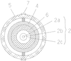
図3に示すような、従来のレーザ用ファイバ等の高エネルギーファイバの接続部であるコネクタにおいて、光ファイバを金属スリーブあるいはフェルール等の光ファイバ固定部材に接着材を用いて固定した場合、発生した熱により、接着剤が膨張することにより、光ファイバに側圧が掛かり、光ファイバのマイクロベンデングにより、伝送損失が発生するとともに、光ファイバの側面からの露光が急激に増加し、ひいては光ファイバを焼損してしまうという問題が発生していた。そして、この問題は、レーザ出力が100W程度のレーザではあまり生じる問題でなかったが、200W以上のハイパワーになるとより顕著に生じることが分かった。
また、接着材で光ファイバを固定する場合には、熱劣化や経年変化により、接続部の耐久性の問題も生じていた。
そこで、これらの問題を解消するため、接着剤の代わりに、ガラス接合用特殊高温はんだを用いる方法が提案された。(特許文献1)
しかし、この方法は超音波装置による超音波加熱を行なう必要があり安価な方法ではなかった。さらに、この方法で使用する、はんだは鉛を主成分とするガラス接合用特殊はんだであって、作業時あるいは製品廃棄時において環境面での問題もあった。
As shown in FIG. 3, in a connector which is a connection portion of a conventional high energy fiber such as a laser fiber, it occurred when an optical fiber was fixed to an optical fiber fixing member such as a metal sleeve or a ferrule by using an adhesive. When the adhesive expands due to heat, a side pressure is applied to the optical fiber, and transmission loss occurs due to the microbending of the optical fiber, and the exposure from the side of the optical fiber increases abruptly. The problem of burning out occurred. This problem is not a problem that occurs so much with lasers with a laser output of about 100 W, but it has been found that the problem occurs more significantly when the power is higher than 200 W.
In addition, when the optical fiber is fixed with an adhesive, there has been a problem of durability of the connection part due to thermal deterioration and aging.
Therefore, in order to solve these problems, a method of using a special high-temperature solder for glass bonding instead of an adhesive has been proposed. (Patent Document 1)
However, this method is not an inexpensive method because it requires ultrasonic heating by an ultrasonic device. Furthermore, the solder used in this method is a special solder for glass joining mainly composed of lead, and there is an environmental problem at the time of work or product disposal.
本発明の課題は、上記の課題を解消するとともに、光ファイバの端部においてスリーブが挿通され、さらに、その外周に金属製コネクタが装着された光ファイバコネクタにおいて、光ファイバの焼損防止並びに耐久性を改善させることにある。 An object of the present invention is to solve the above-mentioned problems, and in an optical fiber connector in which a sleeve is inserted at the end of the optical fiber and a metal connector is attached to the outer periphery of the optical fiber connector. It is to improve.
本発明者は、少なくとも一部が金属スリーブの内面に沿った形状のガイド部材上に光ファイバを固定した上で、ガイド部材を金属スリーブ内に挿通・固定することで、金属スリーブの膨張あるいは接着剤の膨張による光ファイバへの側圧が防止できることを想到し本発明に到達した。 The present inventor fixes or expands the metal sleeve by fixing the optical fiber on the guide member having a shape at least partially along the inner surface of the metal sleeve and inserting and fixing the guide member into the metal sleeve. The inventors have arrived at the present invention by conceiving that side pressure on the optical fiber due to the expansion of the agent can be prevented.
本発明によれば、光ファイバ、該光ファイバを固定するガイド部材、該ガイド部材が挿通・固定されたスリーブ及び該スリーブの外側にコネクタ本体が装着された光ファイバコネクタにおいて、該光ファイバが該ガイド部材表面に固定されているととともに、該ガイド部材と該スリーブの内面との間に空隙が形成されていることを特徴とする光ファイバコネクタが提供される。 According to the present invention, in an optical fiber, a guide member for fixing the optical fiber, a sleeve in which the guide member is inserted and fixed, and an optical fiber connector in which a connector main body is mounted outside the sleeve, the optical fiber is An optical fiber connector is provided that is fixed to the surface of the guide member and has a gap formed between the guide member and the inner surface of the sleeve.
本発明の光ファイバコネクタにあっては、以下に記載した優れた効果が期待できる。
(1)ガイド部材とスリーブとの間には空隙が形成されているので、接着剤が熱膨張しても光ファイバには接着剤の熱膨張による側圧が印加されないので光ファイバの焼損を防止できるとともに、光ファイバの側面からの露光を防止できる。
(2)従来と比較し接着剤の使用量を最小限としたので、経年変化が少なく、耐久性が向上する。
(3)超音波加熱器等特殊な装置を必要とせず、製造工程が簡略化される。
In the optical fiber connector of the present invention, the excellent effects described below can be expected.
(1) Since a gap is formed between the guide member and the sleeve, even if the adhesive is thermally expanded, no side pressure due to the thermal expansion of the adhesive is applied to the optical fiber, so that the optical fiber can be prevented from being burned out. At the same time, exposure from the side surface of the optical fiber can be prevented.
(2) Since the amount of adhesive used is minimized as compared with the prior art, there is little secular change and durability is improved.
(3) A special apparatus such as an ultrasonic heater is not required, and the manufacturing process is simplified.
以下、本発明の光ファイバコネクタの実施形態の一例としてレーザ用ファイバコネクタの例につき、添付図面に基づいて説明する。
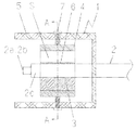
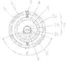
図1〜図2において、1は光ファイバコネクタ、2は光ファイバ、2aは光ファイバ2のコア、2bは光ファイバ2のクラッド、2cは被覆、3は光ファイバ2を中心に固定するためのガイド部材、4はガイド部材3を収納固定するスリーブ、5はスリーブ4を固定するコネクタ本体、6は光ファイバ2並びにガイド部材3を固定する接着剤、7はスリーブ4をコネクタ本体5に固定する止めねじ、Sはガイド部材3とスリーブ4の内面との間の空隙である。θは図2に示すようにスリーブの中央(光ファイバ2の中心)とガイド部材の両端部を結ぶ2本の直線間のなす角で、ここではスリーブ4の内面でのガイド部材の接触角と定義している。
ここで、特徴的なことは、ガイド部材3とスリーブ4の内面との間に空隙Sが形成されていることである。
Hereinafter, an example of a fiber connector for a laser as an example of an embodiment of an optical fiber connector of the present invention will be described with reference to the accompanying drawings.
1 to 2, 1 is an optical fiber connector, 2 is an optical fiber, 2 a is a core of the
Here, what is characteristic is that a gap S is formed between the
こうすることにより、接着剤6が熱膨張しても、ガイド部材3とスリーブ4の内面との間の空隙Sに熱膨張力が分散するので光ファイバ2には熱膨張に起因する側圧が掛かりにくくなるので、光ファイバは変形することなく形状が維持されるのでマイクロベンデイング現象が生ずることは無く側面からの露光を防止できるとともに、光ファイバ2の焼損が防止できる。
By doing so, even if the
ここで、空隙Sは接着剤6及びスリーブ4の熱膨張による熱膨張力を十分に分散させ、光ファイバ2に側圧として作用しないためにもスリーブ4の断面積の50%〜90%であることが好ましい。
また、本発明ではガイド部材3の一部、スリーブ4に接する面をスリーブ4の内面に沿った形状としているが、これは、光ファイバ2及びガイド部材3をスリーブ4の中心に偏心することなく高精度で固定するためである。
図2では、ガイド部材3の形状を円筒形のスリーブ4の内面形状に従って、略半円筒形の形状としたが、ガイド部材3がスリーブ4に接する接触面積及び空隙S及び、光ファイバ2の固定作業を考慮するとガイド部材3がスリーブ4に接する接触角θは2度〜180度であることが好ましい。
さらに、ガイド部材3は必ずしも左右対称の形状である必要はなく、また、光ファイバ2を固定する側の面も必ずしも平面とする必要はなく、曲面でも良く、各種の形状が選択可能である。また、ガイド部材3は熱膨張を防止するためにも金属よりもむしろ、熱膨張率の少ない耐熱性ガラスであることが好ましい。
また、ガイド部材3のスリーブ4の内面への固定方法としては融着、接着、挿入等各種の固定方法があるが、工数を削減し、光ファイバ2及びガイド部材3へのストレスをできるだけ少なくするために光ファイバ2のガイド部材3への固定と同様、熱膨張率の小さい耐熱性接着剤を少量使用し固定するのが望ましい。図1、図2の態様では、スリーブ4に接するガイド部材3の全範囲に接着剤を薄く塗布しスリーブ4の内面に固定した。
Here, the gap S is 50% to 90% of the cross-sectional area of the sleeve 4 in order to sufficiently disperse the thermal expansion force due to the thermal expansion of the
Further, in the present invention, a part of the
In FIG. 2, the shape of the
Furthermore, the
Further, there are various fixing methods such as fusion, adhesion, and insertion as the fixing method of the
一方、光ファイバ2のガイド部材3上への固定については、ガイド部材3からの熱膨張をできるだけ受けないためにも面接触でなく長手方向に線接触状態で固定することが望ましい。
また、光ファイバ2のガイド部材3への固定方法としては融着、接着、挿入等各種の固定方法があるが、工数を削減し、光ファイバ2への周辺部材の熱膨張による側圧をできるだけ少なくするためにも熱膨張率の小さい耐熱性接着剤6をできるだけ少なめに使用するのが望ましい。図1、図2の態様ではガイド部材3に接する箇所には接着剤6を使用せず、光ファイバ2が直接ガイド部材3に接触する様にし、それ以外の光ファイバ2の外周に接着剤6を塗布し固定した。なお、接着剤6の透明度についてもより高い光学接着剤がより好ましい。
On the other hand, for fixing the
There are various methods for fixing the
光ファイバ2としては、レーザ用ファイバに適した石英ガラス等の耐熱性に優れたガラスファイバの常用品を用いればよく、光ファイバの外径としては0.08mm〜3mmのものを使用すればよい。また、スリーブ4としては、金属、ガラス、樹脂等各種選択可能であるが、強度、耐熱性、放熱特性から金属が好ましい。スリーブ4の内径は1mm以上、厚さが0.5mm以上であるものが好ましく用いられる。
最後に、コネクタ本体5についても、スリーブ4と同様、金属、ガラス、樹脂等各種選択可能であるが、強度、耐熱性から金属が好ましい。
なお、本態様ではコネクタ本体5に2箇所ネジ孔を設け、止めネジ7により金属スリーブ4を上下2点で固定しているので光ファイバ2の確実な固定ができる。
As the
Finally, the
In this embodiment, the connector
さらに、本態様において、図示していないが、光ファイバ2の入射端近傍、コネクタ本体5のクラッド2bの外周にクラッド伝搬光を逃がすための耐熱部材を挿通してもよい。
こうすることで、入射端により近い部分でクラッド伝搬光が除去できるのでより一層の放熱効果が期待できる。耐熱部材としては、クラッドより屈折率の高いサファイアやダイヤモンドやガラスが使用される。
さらに、図1、図2に示す態様ではコネクタ本体5として、ねじ式コネクタを使用したが、この他チャック式コネクタを使用する等、これに限定されることなく各種コネクタが使用可能である。
Further, in this aspect, although not shown, a heat-resistant member for allowing clad propagation light to escape may be inserted in the vicinity of the incident end of the
By doing so, the clad propagation light can be removed at a portion closer to the incident end, so that a further heat radiation effect can be expected. As the heat-resistant member, sapphire, diamond or glass having a refractive index higher than that of the cladding is used.
Furthermore, although the screw type connector is used as the
以下は、図1、図2に示す光ファイバコネクタ1の実施例である。
先ず、全長が5000mm、線径が0.125mmの石英ファイバからなる光ファイバ2の両端部4cm程度の被覆層2cを除去しクラッド2bを露出させた。
次に、長さが15mm、外径が3mm、スリーブとの接触角θが略180度の半円筒状の石英ガラスからなるガイド部材3を用意し、中央部長手方向に光ファイバ2を線接触状態で固定した。この際、光ファイバ2のガイド部材3と接触していない空隙S側の光ファイバ2の表面には耐熱性接着剤6を塗布し固定した。
次に、長さが42.5mm、内径が3.5mm、厚さ6.25mmのアルミ二ウムからなる円筒形状のスリーブ4を用意し、先ほど作成した、光ファイバ2が固定されたガイド部材3をスリーブ4内に挿通・固定する。なお、固定方法は耐熱性接着剤6にて固定した。
さらに、ガイド部材3が固定されたスリーブ4をコネクタ本体5に挿入、上下2箇所をスリーブ固定ねじ7で固定して、本発明の光ファイバコネクタ1が完成した。
The following is an example of the optical fiber connector 1 shown in FIGS.
First, the coating layer 2c of about 4 cm at both ends of the
Next, a
Next, a cylindrical sleeve 4 made of aluminum having a length of 42.5 mm, an inner diameter of 3.5 mm, and a thickness of 6.25 mm is prepared, and the
Further, the sleeve 4 to which the
このようにして得た光ファイバコネクタを使用して200Wのレーザ照射試験したところ、光ファイバが焼損することなく十分な耐熱性が確保されていることが確認できた。 When a 200 W laser irradiation test was performed using the optical fiber connector thus obtained, it was confirmed that sufficient heat resistance was ensured without burning the optical fiber.
以上の例は、本発明の一例に過ぎず、本発明の思想の範囲内であれば、種々の変更および応用が可能であることは言うまでもない。例えば、本発明の光ファイバコネクタは、その設置空間に応じた形状に対して、種々変形されて供されることは言うまでもない。 The above examples are merely examples of the present invention, and it goes without saying that various modifications and applications are possible within the scope of the idea of the present invention. For example, it goes without saying that the optical fiber connector of the present invention is provided with various modifications with respect to the shape corresponding to the installation space.
1 光ファイバコネクタ
2 光ファイバ
2a 光ファイバのコア
2b 光ファイバのクラッド
2c 光ファイバの被覆
3 ガイド部材
4 スリーブ
5 コネクタ本体
6 接着剤
7 止めねじ
S 空隙
θ スリーブ4とガイド部材の接触角
DESCRIPTION OF SYMBOLS 1
4
Claims (8)
The optical fiber connector according to claim 1, which is useful as a laser fiber.
Priority Applications (1)
| Application Number | Priority Date | Filing Date | Title |
|---|---|---|---|
| JP2010054052A JP2011186355A (en) | 2010-03-11 | 2010-03-11 | Optical fiber connector |
Applications Claiming Priority (1)
| Application Number | Priority Date | Filing Date | Title |
|---|---|---|---|
| JP2010054052A JP2011186355A (en) | 2010-03-11 | 2010-03-11 | Optical fiber connector |
Publications (1)
| Publication Number | Publication Date |
|---|---|
| JP2011186355A true JP2011186355A (en) | 2011-09-22 |
Family
ID=44792661
Family Applications (1)
| Application Number | Title | Priority Date | Filing Date |
|---|---|---|---|
| JP2010054052A Pending JP2011186355A (en) | 2010-03-11 | 2010-03-11 | Optical fiber connector |
Country Status (1)
| Country | Link |
|---|---|
| JP (1) | JP2011186355A (en) |
-
2010
- 2010-03-11 JP JP2010054052A patent/JP2011186355A/en active Pending
Similar Documents
| Publication | Publication Date | Title |
|---|---|---|
| JP2019070807A (en) | Optoelectronic integration device | |
| US6282349B1 (en) | Launch fiber termination | |
| US7306376B2 (en) | Monolithic mode stripping fiber ferrule/collimator and method of making same | |
| US9964706B2 (en) | Structure of an input end of an optical fiber | |
| CN103998963B (en) | Optical Fiber Components and Laser Devices | |
| WO2007116792A1 (en) | Light input/output port of optical component and beam converting apparatus | |
| US10431951B2 (en) | Leakage light removal structure and fiber laser | |
| JP6678286B2 (en) | Optical fiber assembly and optical coupling device, optical fiber coupling device | |
| US20070292087A1 (en) | Apparatus and method for diffusing laser energy that fails to couple into small core fibers, and for reducing coupling to the cladding of the fiber | |
| CN111786247B (en) | A cascade type cladding light stripper and a manufacturing method thereof | |
| JPWO2017026072A1 (en) | Optical connection parts | |
| CN108761646A (en) | A kind of optical fiber pigtail | |
| WO2014208701A1 (en) | Optical receptacle | |
| JP2006220717A (en) | Optical fiber splicing part and optical fiber splicer using the same | |
| JP5155987B2 (en) | Optical fiber end processing method and optical fiber end processing apparatus | |
| JP2007293298A (en) | Optical input / output end of optical components | |
| JP2008164795A (en) | Optical connector | |
| JP6266390B2 (en) | Glass buffer | |
| US8412009B2 (en) | Optical fiber contact | |
| JP2014193806A5 (en) | ||
| JP2016151684A (en) | Optical fiber with ferrule and manufacturing method thereof | |
| WO2018109977A1 (en) | Optical connection part | |
| JP2011186355A (en) | Optical fiber connector | |
| JP2025103281A (en) | Optical fiber connection body and method for manufacturing the same | |
| CN213338100U (en) | Optical fiber pigtail of laser |