JP2011185503A - Temperature control method - Google Patents
Temperature control method Download PDFInfo
- Publication number
- JP2011185503A JP2011185503A JP2010050167A JP2010050167A JP2011185503A JP 2011185503 A JP2011185503 A JP 2011185503A JP 2010050167 A JP2010050167 A JP 2010050167A JP 2010050167 A JP2010050167 A JP 2010050167A JP 2011185503 A JP2011185503 A JP 2011185503A
- Authority
- JP
- Japan
- Prior art keywords
- pipe
- temperature control
- heat storage
- temperature
- hot water
- Prior art date
- Legal status (The legal status is an assumption and is not a legal conclusion. Google has not performed a legal analysis and makes no representation as to the accuracy of the status listed.)
- Pending
Links
Images

Landscapes
- Steam Or Hot-Water Central Heating Systems (AREA)
- Central Heating Systems (AREA)
Abstract
Description
本発明は、温度制御が簡便になるとともに、安全性に優れ、省エネ効果にも優れた温度制御方法に関するものである。 The present invention relates to a temperature control method that is simple in temperature control, excellent in safety, and excellent in energy saving effect.
パイプ管内に水やオイル等の液体を循環させて温度を制御する方法は、様々な分野で採用されている。
例えば、温水式の床・壁暖房システムにおいては、空間内を暖房するため、床や壁にパイプ管をはりめぐらせ、該パイプ管内に温水等の液体を循環させる方法が採用されている。
また、自動車、電車、船舶、航空等の動力装置や、製鉄、プラスチック等の製造装置、あるいは種々の熱処理装置においても、温度上昇による故障等を防ぐため、パイプ管を用いて冷却水等の液体を循環させる方法が採用されている。
近年では、パソコン等の電子機器などにおいても、パイプ管を用いて冷却水等の液体を循環させるなど、様々な用途で、パイプ管を用いた温度制御方法が採用されている。
A method of controlling the temperature by circulating a liquid such as water or oil in a pipe pipe has been adopted in various fields.
For example, in a hot water type floor / wall heating system, in order to heat the space, a method of circulating a pipe such as hot water around the floor or wall and circulating a liquid such as hot water is adopted.
In addition, in power equipment for automobiles, trains, ships, aviation, etc., steel manufacturing equipment, plastic manufacturing equipment, and various heat treatment equipment, liquids such as cooling water using pipe pipes are used to prevent failures due to temperature rise. The method of circulating is adopted.
In recent years, a temperature control method using a pipe pipe has been adopted in various applications such as circulating a liquid such as cooling water using a pipe pipe in electronic devices such as personal computers.
このような温度制御方法では、温度制御の効率を上げるため、用いるパイプ管は、熱伝導に優れる金属製のものが多く採用されている。また、温度制御の効率を上げるため、躯体とパイプ管は接するように配置されているものが多い。
例えば、温水式床暖房においては、パイプ管は予めコンクリートやモルタル等の床材に埋め込まれて用いるタイプが多く採用されている。
このような温水式床暖房においては、昼夜問わず長期間循環し続けるものが多く、床材自体が常に蓄熱された状態であり、パイプ管の種類等に関わらず、急激な温度変化が少なく、また温度ロスも少なく、電源のON・OFFなどによるエネルギー消費量等も、それほど問題視されることはなかった。
In such a temperature control method, in order to increase the efficiency of temperature control, many pipes made of metal excellent in heat conduction are employed. Further, in order to increase the efficiency of temperature control, the casing and the pipe tube are often arranged so as to contact each other.
For example, in hot water type floor heating, a pipe pipe is often used by being embedded in a floor material such as concrete or mortar in advance.
In such warm water type floor heating, there are many things that continue to circulate for a long time regardless of day and night, the flooring itself is always in a stored state, and there is little rapid temperature change regardless of the type of pipe pipe, In addition, there was little temperature loss and energy consumption due to power ON / OFF etc. was not considered as a problem.
しかし近年、温水式床暖房が普及しはじめるにつれ、簡易式のパネル型温水式床暖房が登場し、夜の短期間だけ暖房したり、ある部分だけ部分暖房するタイプが現れ、電源ON時から、より短い時間で目的とする温度に到達できる床暖房システムが望まれるようになってきた。さらに、人々のエコ環境意識の高まりにより、より安全で、より省エネ効果の高い製品が望まれるようになってきた。 However, in recent years, as hot water floor heating has begun to spread, simple panel type hot water floor heating has appeared, and there are types that heat only for a short period of time or partially heat only at night, and when the power is turned on, A floor heating system that can reach a target temperature in a shorter time has been desired. Furthermore, people's awareness of the eco-environment has increased the desire for safer and more energy-saving products.
そのような状況下、温水式床暖房システムにおいては、次のような問題が挙げられる。
素早く暖房するためには、床材自体の暖房など必要以上に温度を放出しなければならず、特に、パネル型温水式床暖房においては温度ロスが多くなるため、エネルギー消費量も問題になることがある。
さらに、床材とパイプ管が接している部分において、パイプ管近傍の急激な温度変化により、パイプ管近傍の床材が急激に温度変化を起こし、床材の温度ムラの問題や、場合によっては低温火傷等の危険の恐れがある。
Under such circumstances, there are the following problems in the hot water type floor heating system.
In order to heat quickly, it is necessary to release the temperature more than necessary, such as heating the flooring itself, and especially in panel type hot water type floor heating, the temperature loss increases, so energy consumption is also a problem. There is.
Furthermore, in the part where the flooring and the pipe pipe are in contact, the temperature change in the vicinity of the pipe pipe suddenly changes due to the rapid temperature change in the vicinity of the pipe pipe, and the problem of temperature unevenness of the flooring, and in some cases There is a risk of low temperature burns.
このような問題に対し、例えば特許文献1では、温水式床暖房において、温水パイプの間の空間部に、蓄熱部材を配置する方法が記載されている。
しかし、特許文献1のように蓄熱部材が多い場合、電源ON時に、本来なら床表面へと移動する熱が蓄熱部材へと移動し、床表面の暖房が遅れる、という問題があった。また、蓄熱部材が多くても、それに似合う蓄熱効果は発揮されない問題もあった。
For example, Patent Document 1 discloses a method for disposing a heat storage member in a space between hot water pipes in a hot water type floor heating system.
However, when there are many heat storage members as in Patent Document 1, there is a problem that when the power is turned on, the heat that originally moves to the floor surface moves to the heat storage member and the heating of the floor surface is delayed. Moreover, even if there were many heat storage members, there existed a problem that the heat storage effect which suits it was not exhibited.
このような問題に対し、本発明者らが鋭意検討を行った結果、パイプ管近傍の急激な温度変化を抑えるとともに、パイプ管内の液体を目的の温度とするためのエネルギー消費を抑えることができる、温度制御方法を見出し、本発明の完成に至った。 As a result of intensive studies by the present inventors on such a problem, it is possible to suppress a rapid temperature change in the vicinity of the pipe pipe and to suppress energy consumption for setting the liquid in the pipe pipe to a target temperature. The present inventors have found a temperature control method and have completed the present invention.
すなわち、本発明は以下の特徴を有するものである。
1.躯体にパイプ管をはりめぐらせ、該パイプ管内に液体を循環させて温度を制御する温度制御方法において、パイプ管の外側に蓄熱材を被覆させることを特徴とする温度制御方法。
2.床材基礎部に、パイプ管をはりめぐらせ、該パイプ管内に温水を循環させて温度を制御する温水式床暖房の温度制御方法において、パイプ管の外側に蓄熱材を被覆させることを特徴とする温水式床暖房の温度制御方法。
That is, the present invention has the following characteristics.
1. A temperature control method for controlling a temperature by circulating a pipe pipe through a casing and circulating a liquid in the pipe pipe, and covering the outside of the pipe pipe with a heat storage material.
2. In a temperature control method for hot water type floor heating, in which a pipe pipe is placed around a floor material base, and the temperature is controlled by circulating hot water in the pipe pipe, the heat storage material is coated on the outside of the pipe pipe. Temperature control method for hot water floor heating.
本発明は、パイプ管による温度制御方法において、パイプ管近傍の急激な温度変化を抑えるとともに、パイプ管内の液体を目的の温度とするためのエネルギー消費を抑えることができる。 According to the present invention, in a temperature control method using a pipe, it is possible to suppress an abrupt temperature change in the vicinity of the pipe and reduce energy consumption for setting the liquid in the pipe to a target temperature.
1:床材基礎部
2:温水パイプ
3:温度制御装置及びポンプ
4:床材
5:蓄熱材
6:温度センサーA
7:温度センサーB
1: Floor material base part 2: Hot water pipe 3: Temperature control device and pump 4: Floor material 5: Heat storage material 6: Temperature sensor A
7: Temperature sensor B
以下、本発明を実施するための形態について説明する。 Hereinafter, modes for carrying out the present invention will be described.
本発明の温度制御方法は、躯体にパイプ管をはりめぐらせ、該パイプ管内に液体を循環させて温度を制御する温度制御方法であり、該パイプ管の外側に蓄熱材を被覆させることを特徴とするものである。 The temperature control method of the present invention is a temperature control method for controlling the temperature by circulating a pipe pipe in a casing and circulating a liquid in the pipe pipe, and is characterized by covering the outside of the pipe pipe with a heat storage material. It is what.
本発明の温度制御方法が適用できる躯体としては、例えば、床・壁暖房システムにて使用される基材、自動車、電車、船舶、航空等の動力装置や、製鉄、プラスチック等の製造装置、あるいは種々の熱処理装置にて使用される基板、パソコン等の電子機器にて使用される基板等が挙げられる。 As a housing to which the temperature control method of the present invention can be applied, for example, a base material used in a floor / wall heating system, a power device such as an automobile, a train, a ship, an aviation, a manufacturing apparatus such as iron making or plastic, or Examples include substrates used in various heat treatment apparatuses, substrates used in electronic devices such as personal computers, and the like.
本発明の温度制御方法で用いるパイプ管としては、銅、アルミ、鉄、亜鉛、ステンレス、真鍮等の金属製、塩化ビニル、ポリエチレン、ポリプロピレン等の樹脂製等、特に限定されず用いることができる。また、パイプ管の種類、口径等も特に限定されず、適宜設定して使用すればよい。 The pipe pipe used in the temperature control method of the present invention can be used without particular limitation, such as made of metal such as copper, aluminum, iron, zinc, stainless steel, and brass, or resin such as vinyl chloride, polyethylene, and polypropylene. Moreover, the kind of pipe pipe, the diameter and the like are not particularly limited, and may be appropriately set and used.
本発明では、該パイプ管の外側に蓄熱材を被覆させることを特徴とするものである。
蓄熱材としては、無機塩、無機水和塩、および共融混合物等の無機蓄熱材、脂肪族炭化水素、長鎖アルコール、長鎖脂肪酸、長鎖脂肪酸エステル、ポリエーテル化合物、脂肪酸トリグリセリド等の有機蓄熱材が挙げられる。
In the present invention, a heat storage material is coated on the outside of the pipe pipe.
Examples of the heat storage material include inorganic heat storage materials such as inorganic salts, inorganic hydrated salts, and eutectic mixtures, aliphatic hydrocarbons, long chain alcohols, long chain fatty acids, long chain fatty acid esters, polyether compounds, fatty acid triglycerides, and other organic materials. A heat storage material is mentioned.
本発明の蓄熱材を被覆させる方法としては、特に限定されないが、例えば、蓄熱材とともにバインダーを混合して蓄熱組成物を得、該蓄熱組成物をパイプ管の外側に被覆させ、該蓄熱組成物を固形化させる方法等が挙げられる。このような方法では、蓄熱組成物をパイプ管表面に直接塗付して乾燥させることもできるし、パイプ管をはりめぐらせた後、パイプ管近傍に流し込んで固形化させることもできる。なお、蓄熱材は、カプセル化された状態や多孔体に担持された状態で混合してもよい。 The method for coating the heat storage material of the present invention is not particularly limited. For example, the heat storage composition is obtained by mixing a binder together with the heat storage material, and the heat storage composition is coated on the outside of the pipe, and the heat storage composition. The method etc. which solidify is mentioned. In such a method, the heat storage composition can be applied directly to the surface of the pipe tube and dried, or after the pipe tube has been wound, it can be poured into the vicinity of the pipe tube to be solidified. The heat storage material may be mixed in an encapsulated state or in a state of being supported on a porous body.
バインダーとしては、特に限定されないが、アクリル樹脂、シリコン樹脂、ポリエステル樹脂、アルキッド樹脂、エポキシ樹脂、ウレタン樹脂、フェノール樹脂、メラミン樹脂、アミノ樹脂、ポリカーボネート樹脂、フッ素樹脂、酢酸ビニル樹脂、塩化ビニル樹脂、ABS樹脂、AS樹脂、クロロプレンゴム、スチレン−ブタジエンゴム、アクリルニトリル−ブタジエンゴム、ブタジエンゴム等の合成ゴム等の有機バインダー、ポルトランドセメント、高炉セメント、シリカセメント、フライアッシュセメント、白色セメント、焼石膏、コロイダルシリカ、水溶性珪酸アルカリ金属塩等の無機結合剤等が挙げられる。 The binder is not particularly limited, but acrylic resin, silicon resin, polyester resin, alkyd resin, epoxy resin, urethane resin, phenol resin, melamine resin, amino resin, polycarbonate resin, fluorine resin, vinyl acetate resin, vinyl chloride resin, Organic binders such as ABS resin, AS resin, chloroprene rubber, styrene-butadiene rubber, acrylonitrile-butadiene rubber, synthetic rubber such as butadiene rubber, Portland cement, blast furnace cement, silica cement, fly ash cement, white cement, calcined gypsum, Examples thereof include inorganic binders such as colloidal silica and water-soluble alkali metal silicates.
また蓄熱組成物としては、バインダーのほかに、顔料、骨材、粘性調整剤、可塑剤、緩衝剤、分散剤、架橋剤、pH調整剤、防腐剤、防黴剤、抗菌剤、防藻剤、湿潤剤、消泡剤、発泡剤、レベリング剤、顔料分散剤、沈降防止剤、たれ防止剤、凍結防止剤、滑剤、脱水剤、艶消し剤、紫外線吸収剤、酸化防止剤、光安定剤、繊維類、香料、化学物質吸着剤、光触媒、吸放湿性粉粒体、熱伝導性物質、難燃剤、層状粘土鉱物、相溶化剤等の添加剤を含有することもできる。
また蓄熱組成物中の蓄熱材の含有量としては、10重量%以上、好ましくは30重量%以上、さらに好ましくは50重量%以上であることが好ましい。
In addition to binders, heat storage compositions include pigments, aggregates, viscosity modifiers, plasticizers, buffers, dispersants, crosslinking agents, pH adjusters, antiseptics, antifungal agents, antibacterial agents, and algaeproofing agents. , Wetting agent, antifoaming agent, foaming agent, leveling agent, pigment dispersant, anti-settling agent, anti-sagging agent, anti-freezing agent, lubricant, dehydrating agent, matting agent, UV absorber, antioxidant, light stabilizer Further, additives such as fibers, fragrances, chemical adsorbents, photocatalysts, moisture absorbing / releasing powders, heat conductive materials, flame retardants, layered clay minerals, and compatibilizers can also be contained.
The content of the heat storage material in the heat storage composition is preferably 10% by weight or more, preferably 30% by weight or more, and more preferably 50% by weight or more.
蓄熱材の被覆量としては、パイプ管表面に対し、蓄熱材0.01g/cm2以上5.0g/cm2以下(好ましくは、0.1g/cm2以上3.0g/cm2)程度被覆させることが好ましい。被覆量が少なすぎると、パイプ管近傍の急激な温度変化が抑えられない場合がある。被覆量が多すぎると、蓄熱材が熱・冷熱を奪い、余計なエネルギー消費が必要となり、即効性に欠ける場合がある。また、それ以上蓄熱材を被覆させたとしても、蓄熱効果が発揮できない場合がある。 The amount of the heat storage material covered is about 0.01 g / cm 2 to 5.0 g / cm 2 (preferably 0.1 g / cm 2 to 3.0 g / cm 2 ) of the heat storage material on the pipe tube surface. It is preferable to make it. If the coating amount is too small, a sudden temperature change in the vicinity of the pipe may not be suppressed. If the amount of coating is too large, the heat storage material may take away heat and cold, and extra energy consumption is required, which may lack immediate effect. Further, even if the heat storage material is further covered, the heat storage effect may not be exhibited.
パイプ管内を循環する液体としては、水やオイル等が挙げられ、液体内に、蓄熱材や凍結防止剤、防腐剤等の添加剤が含まれていてもよい。 Examples of the liquid circulating in the pipe pipe include water and oil, and the liquid may contain additives such as a heat storage material, an antifreezing agent, and an antiseptic.
本発明の温度制御方法では、液体を循環させるためのポンプ、液体温度を制御するために加熱・冷却装置等は、特に限定されず公知のものが使用できる。 In the temperature control method of the present invention, the pump for circulating the liquid and the heating / cooling device for controlling the liquid temperature are not particularly limited, and known ones can be used.
以下、温度制御方法として、温水式床暖房を具体例とし、実施例、比較例を述べる。 Hereinafter, as a temperature control method, a hot water type floor heating will be taken as a specific example, and examples and comparative examples will be described.
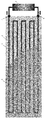
図1に示すように、15℃雰囲気下で、床材基礎部(躯体)(1)に、パイプ管(温水パイプ(2))をはりめぐらせ、表面に床材(4)を積層した温水式床暖房を設置した。
なお、該温水パイプ(2)には、温度センサー(6、7)と、温度センサーの情報を基に温度を制御する温度制御装置(3)、及び、液体を循環させるためのポンプ(3)が設置してあり、温水パイプ内を循環する液体の流量、温度等を制御できるようになっている。
As shown in FIG. 1, in a 15 ° C. atmosphere, hot water in which a pipe base (hot water pipe (2)) is placed over a floor base (casing) (1) and the floor (4) is laminated on the surface. A floor heating system was installed.
The hot water pipe (2) includes a temperature sensor (6, 7), a temperature control device (3) for controlling the temperature based on the information of the temperature sensor, and a pump (3) for circulating the liquid. Is installed so that the flow rate and temperature of the liquid circulating in the hot water pipe can be controlled.
図2(図1A−A´断面図)に示すように、床材基礎部(1)には、温水パイプ(2)をはりめぐらせるように、凹部構造となっている箇所が存在し、該凹部構造に温水パイプ(2)を嵌め込んで使用する。
この際に、凹部構造内に蓄熱組成物(蓄熱材(5))を流し込んで固形化させ、温水パイプ(2)の外側を蓄熱材(5)で被覆したもの(図2(a)、実施例1)(蓄熱材被覆量:0.7〜2.5g/cm2)と、温水パイプ(2)の外側を被覆しないもの(図2(b)、比較例1)とを用意した。
なお、床材基礎部(1)としては木質材料(1800mm×600mm×15mm)、温水パイプ(2)としては、塩化ビニル製温水パイプ(外径10mm、内径6mm)を用いた。また、蓄熱材(5)としては、パラフィンワックス(相変化温度49℃)を用い、バインダーとしてスチレン−ブタジエンエラストマーを用いて、蓄熱材(5)を70重量%含む蓄熱組成物を作製し、該蓄熱組成物を使用した。
As shown in FIG. 2 (FIG. 1A-A ′ cross-sectional view), the floor material base portion (1) has a portion having a concave structure so that the hot water pipe (2) is inserted, and the concave portion A hot water pipe (2) is fitted into the structure.
At this time, the heat storage composition (heat storage material (5)) was poured into the recess structure to be solidified, and the outside of the hot water pipe (2) was covered with the heat storage material (5) (FIG. 2 (a), implementation) Example 1) (Heat storage material coating amount: 0.7 to 2.5 g / cm 2 ) and one not covering the outside of the hot water pipe (2) (FIG. 2B, Comparative Example 1) were prepared.
In addition, a woody material (1800 mm × 600 mm × 15 mm) was used as the floor base (1), and a hot water pipe made of vinyl chloride (outer diameter 10 mm, inner diameter 6 mm) was used as the hot water pipe (2). Further, as the heat storage material (5), paraffin wax (phase change temperature 49 ° C.) is used, and a styrene-butadiene elastomer is used as a binder to prepare a heat storage composition containing 70% by weight of the heat storage material (5), A heat storage composition was used.
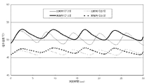
温度測定試験として、温水温度を50℃、温水流量1リットル/minとし、温水入口温度(温度センサー(6))と、温水出口温度(温度センサー(7))を経時的に測定した。結果は、図3に示すとおり、実施例1は、比較例1に比べ、温水温度を50℃領域に保つためのON−OFF切り替え期間が長くなり、エネルギー消費量を制御することができた。
As a temperature measurement test, the hot water temperature was 50 ° C., the hot water flow rate was 1 liter / min, and the hot water inlet temperature (temperature sensor (6)) and hot water outlet temperature (temperature sensor (7)) were measured over time. As a result, as shown in FIG. 3, compared with Comparative Example 1, Example 1 has a longer ON-OFF switching period for maintaining the hot water temperature in the 50 ° C. region, and was able to control energy consumption.
Claims (2)
パイプ管の外側に蓄熱材を被覆させることを特徴とする温度制御方法。 In a temperature control method for controlling the temperature by circulating a liquid in the pipe pipe through the pipe pipe in the casing,
A temperature control method characterized in that a heat storage material is coated on the outside of a pipe tube.
パイプ管の外側に蓄熱材を被覆させることを特徴とする温水式床暖房の温度制御方法。
In the temperature control method of the hot water type floor heating in which the pipe pipe is passed through the floor material base and the temperature is controlled by circulating hot water in the pipe pipe.
A temperature control method for hot water floor heating, characterized in that a heat storage material is coated on the outside of a pipe pipe.
Priority Applications (1)
| Application Number | Priority Date | Filing Date | Title |
|---|---|---|---|
| JP2010050167A JP2011185503A (en) | 2010-03-08 | 2010-03-08 | Temperature control method |
Applications Claiming Priority (1)
| Application Number | Priority Date | Filing Date | Title |
|---|---|---|---|
| JP2010050167A JP2011185503A (en) | 2010-03-08 | 2010-03-08 | Temperature control method |
Publications (2)
| Publication Number | Publication Date |
|---|---|
| JP2011185503A true JP2011185503A (en) | 2011-09-22 |
| JP2011185503A5 JP2011185503A5 (en) | 2013-04-11 |
Family
ID=44792013
Family Applications (1)
| Application Number | Title | Priority Date | Filing Date |
|---|---|---|---|
| JP2010050167A Pending JP2011185503A (en) | 2010-03-08 | 2010-03-08 | Temperature control method |
Country Status (1)
| Country | Link |
|---|---|
| JP (1) | JP2011185503A (en) |
Cited By (3)
| Publication number | Priority date | Publication date | Assignee | Title |
|---|---|---|---|---|
| KR20140128642A (en) * | 2013-04-29 | 2014-11-06 | 주식회사 디에스시스템 | Panels for floor heating system and the method of floor heating construction using the same |
| JP2016090100A (en) * | 2014-10-31 | 2016-05-23 | 住商メタレックス株式会社 | Hot water mat for floor heating |
| US9766184B2 (en) | 2012-08-11 | 2017-09-19 | Seagate Technology Llc | Surface features characterization |
Citations (5)
| Publication number | Priority date | Publication date | Assignee | Title |
|---|---|---|---|---|
| JPS6141513U (en) * | 1984-08-20 | 1986-03-17 | 三菱重工業株式会社 | floor heating panel |
| JPH0510533A (en) * | 1991-06-29 | 1993-01-19 | Mitsubishi Cable Ind Ltd | Floor or road surface structure |
| JPH085105A (en) * | 1994-04-22 | 1996-01-12 | Susumu Komatsubara | Method and equipment for indoor cooling and heating |
| JPH08226780A (en) * | 1995-02-20 | 1996-09-03 | Funen Akurosu Kk | Heat radiator, heating apparatus and heat storage pipe |
| JP2000292085A (en) * | 1999-04-06 | 2000-10-20 | Chubu Electric Power Co Inc | Heat storage body, heat storage device and manufacture thereof |
-
2010
- 2010-03-08 JP JP2010050167A patent/JP2011185503A/en active Pending
Patent Citations (5)
| Publication number | Priority date | Publication date | Assignee | Title |
|---|---|---|---|---|
| JPS6141513U (en) * | 1984-08-20 | 1986-03-17 | 三菱重工業株式会社 | floor heating panel |
| JPH0510533A (en) * | 1991-06-29 | 1993-01-19 | Mitsubishi Cable Ind Ltd | Floor or road surface structure |
| JPH085105A (en) * | 1994-04-22 | 1996-01-12 | Susumu Komatsubara | Method and equipment for indoor cooling and heating |
| JPH08226780A (en) * | 1995-02-20 | 1996-09-03 | Funen Akurosu Kk | Heat radiator, heating apparatus and heat storage pipe |
| JP2000292085A (en) * | 1999-04-06 | 2000-10-20 | Chubu Electric Power Co Inc | Heat storage body, heat storage device and manufacture thereof |
Cited By (3)
| Publication number | Priority date | Publication date | Assignee | Title |
|---|---|---|---|---|
| US9766184B2 (en) | 2012-08-11 | 2017-09-19 | Seagate Technology Llc | Surface features characterization |
| KR20140128642A (en) * | 2013-04-29 | 2014-11-06 | 주식회사 디에스시스템 | Panels for floor heating system and the method of floor heating construction using the same |
| JP2016090100A (en) * | 2014-10-31 | 2016-05-23 | 住商メタレックス株式会社 | Hot water mat for floor heating |
Similar Documents
| Publication | Publication Date | Title |
|---|---|---|
| Cao et al. | Microencapsulated phase change materials for enhancing the thermal performance of Portland cement concrete and geopolymer concrete for passive building applications | |
| Sarı et al. | Preparation, characterization, thermal energy storage properties and temperature control performance of form-stabilized sepiolite based composite phase change materials | |
| Sarı | Composites of polyethylene glycol (PEG600) with gypsum and natural clay as new kinds of building PCMs for low temperature-thermal energy storage | |
| Karaipekli et al. | Thermal regulating performance of gypsum/(C18–C24) composite phase change material (CPCM) for building energy storage applications | |
| Xu et al. | Paraffin/diatomite composite phase change material incorporated cement-based composite for thermal energy storage | |
| CN101519560A (en) | Watery acrylic acid insulating mould coating | |
| JP4810189B2 (en) | Thermal insulation | |
| JPWO2010023957A1 (en) | Outside insulation panel | |
| CN107236376A (en) | Aqueous quick-dry type antifogging coating | |
| DE102008004485A1 (en) | Covering of organic and inorganic phase change material, comprises introducing the phase change material into a porous, open-cellular carrier structure and providing the filled porous granulates with water vapor-tight layer | |
| JP2011185503A (en) | Temperature control method | |
| JP2015020383A (en) | Heat storage laminate | |
| KR20120035610A (en) | Composition of mortar | |
| MY139700A (en) | The non-intrusive and extended use of water reservoirs in buildings as thermal storage for heating, ventilation and air conditioning systems | |
| CN109715892A (en) | Heat-barrier material arranges body | |
| CN105384420B (en) | Inorganic heat-insulating coating for blocking heat bridge effect and preparation method thereof | |
| CN102190959A (en) | Inner wall latex paint capable of releasing far-infrared rays | |
| JP2006225986A (en) | Plaster board | |
| JP2010249506A (en) | Heat storage laminate | |
| US6902611B2 (en) | Heat dissipating coating and method for decreasing the inner temperature of buildings and similar constructions | |
| JP2008239860A (en) | Heat-storage medium | |
| Nejat et al. | Phase change material (PCM) as the smart heat-storing concept: a brief review | |
| JP3172272U (en) | Temperature control body | |
| CN107382232A (en) | A kind of phase transformation construction material of inorganic coagulation material encapsulation and preparation method thereof | |
| CN207921504U (en) | A kind of Multifunctional anti-corrosion thermal insulation pipeline |
Legal Events
| Date | Code | Title | Description |
|---|---|---|---|
| A521 | Written amendment |
Free format text: JAPANESE INTERMEDIATE CODE: A523 Effective date: 20130221 |
|
| A621 | Written request for application examination |
Free format text: JAPANESE INTERMEDIATE CODE: A621 Effective date: 20130221 |
|
| A977 | Report on retrieval |
Free format text: JAPANESE INTERMEDIATE CODE: A971007 Effective date: 20131225 |
|
| A131 | Notification of reasons for refusal |
Free format text: JAPANESE INTERMEDIATE CODE: A131 Effective date: 20131226 |
|
| A521 | Written amendment |
Free format text: JAPANESE INTERMEDIATE CODE: A523 Effective date: 20140224 |
|
| A131 | Notification of reasons for refusal |
Free format text: JAPANESE INTERMEDIATE CODE: A131 Effective date: 20140626 |
|
| A02 | Decision of refusal |
Free format text: JAPANESE INTERMEDIATE CODE: A02 Effective date: 20150122 |