JP2011177560A - Hinge mechanism of game machine - Google Patents
Hinge mechanism of game machine Download PDFInfo
- Publication number
- JP2011177560A JP2011177560A JP2011110802A JP2011110802A JP2011177560A JP 2011177560 A JP2011177560 A JP 2011177560A JP 2011110802 A JP2011110802 A JP 2011110802A JP 2011110802 A JP2011110802 A JP 2011110802A JP 2011177560 A JP2011177560 A JP 2011177560A
- Authority
- JP
- Japan
- Prior art keywords
- hinge
- opening
- pin
- frame
- front frame
- Prior art date
- Legal status (The legal status is an assumption and is not a legal conclusion. Google has not performed a legal analysis and makes no representation as to the accuracy of the status listed.)
- Pending
Links
Images


Landscapes
- Pinball Game Machines (AREA)
Abstract
Description
本発明は、遊技機の側部上下に設けられベース部材に対して開閉部材を揺動開閉自在にヒンジ接続させる上下一対のヒンジ機構における一方のヒンジ機構に関する。 The present invention relates to one hinge mechanism in a pair of upper and lower hinge mechanisms which are provided on the upper and lower sides of a gaming machine and hinged to open and close with respect to a base member.
上記のようなヒンジ機構は種々の遊技機に用いられており、その一例として、パチンコ機や雀球遊技機等における外枠と前枠との間に設けられるヒンジ機構があげられる。パチンコ機のヒンジ機構は、外郭方形の枠状に形成された固定保持用の外枠と、外枠の開口面域を覆う開閉搭載用の前枠との間を繋いで互いの正面左側上下に設けられており、前枠に種々の遊技構成部品が取り付けられて構成される遊技機本体が、外枠に対して一体的に横開き開閉可能にヒンジ接続されるようになっている。 The hinge mechanism as described above is used in various game machines, and one example thereof is a hinge mechanism provided between an outer frame and a front frame in a pachinko machine, a sparrow ball game machine, or the like. The hinge mechanism of the pachinko machine connects the outer frame for fixing and holding formed in the shape of an outer rectangular frame and the front frame for opening and closing that covers the opening surface area of the outer frame, and the left and right front and upper sides of each other A gaming machine main body configured by attaching various game components to the front frame is hinge-connected to the outer frame so as to be able to be opened and closed sideways.
ところで、パチンコ機は新機種投入時に遊技者の注目を集めて高い稼働率を発揮する一方、一定期間を経過すると遊技者が他の新台に移動して稼働率が低下する。このため遊技施設では、長期間にわたって稼働率が高い機種(いわゆるヒット機種)を除いて比較的短い周期で新機種と交換する新台入れ替えが行われる。このとき遊技施設の遊技島に釘打ち固定された外枠を取り外して新たな外枠を設置するのは、時間的にも費用的にも効率的でないことから、もとの外枠をそのまま流用して遊技機本体を交換する交換形態が利用される。このため、パチンコ機のヒンジ機構には、外枠と前枠とを相対揺動自在に連結させる機能だけでなく、外枠と前枠とを容易に連結し分離できる機能が求められる。このようなことから、パチンコ機のような遊技機に用いられるヒンジ機構では、ヒンジピン(軸ピン)とピン受容孔(軸孔)との嵌合を基本としたヒンジ機構が多く用いられている(例えば、特許文献1を参照)。 By the way, the pachinko machine attracts the attention of the player when a new model is introduced and exhibits a high operating rate. On the other hand, after a certain period of time, the player moves to another new machine and the operating rate decreases. For this reason, in amusement facilities, a new machine is exchanged with a new model at a relatively short cycle except for models that have a high operation rate over a long period of time (so-called hit models). At this time, it is not efficient in terms of time and cost to remove the outer frame that is nail-fixed to the game island of the gaming facility and install a new outer frame. Thus, an exchange mode for exchanging the gaming machine main body is used. For this reason, the hinge mechanism of the pachinko machine is required to have a function of easily connecting and separating the outer frame and the front frame as well as a function of connecting the outer frame and the front frame so as to be relatively swingable. For this reason, in a hinge mechanism used in a gaming machine such as a pachinko machine, a hinge mechanism based on fitting between a hinge pin (shaft pin) and a pin receiving hole (shaft hole) is often used ( For example, see Patent Document 1).
ところが、前枠に遊技盤や裏セット盤、電源ユニット及び各種制御装置が組付けられた遊技機本体は、外形寸法が52×73cm程度、質量が15〜20kg程度ある重量物であり、このような大型且つ重量物を把持しながら小径のヒンジピンとピン受容孔を位置合わせして連結させることは、熟練した作業者であっても容易な作業ではない。また、この連結作業において、外枠側ヒンジ部材のヒンジピンに前枠側ヒンジ部材の端部をぶつけてヒンジピンを曲げてしまうことがあり、このような場合には、遊技島に釘打ち固定された外枠を取り外して新しい外枠に交換しなければならない、という問題があった。 However, a gaming machine body in which a game board, a back set board, a power supply unit, and various control devices are assembled in the front frame is a heavy object having an outer dimension of about 52 × 73 cm and a mass of about 15 to 20 kg. Even if it is a skilled worker, it is not an easy operation to align and connect a small-diameter hinge pin and a pin receiving hole while gripping a large and heavy object. Also, in this connection work, the hinge pin may be bent by hitting the end portion of the front frame side hinge member against the hinge pin of the outer frame side hinge member. There was a problem that the outer frame had to be removed and replaced with a new outer frame.
また、パチンコ機においては、前枠の前面にガラス扉も前枠と同様にヒンジ機構を介して開閉自在に取り付けられる構成となっている。このように外枠と前枠とを開閉自在に連結する第1ヒンジ機構と、前枠にガラス扉を連結する第2ヒンジ機構を備える遊技機においては、両ヒンジ機構は近接配置される構成となることが多く、両者の構成および配置が複雑化しやすいため、これをできる限り簡単な構成とすることが求められる。 Further, in the pachinko machine, a glass door is attached to the front surface of the front frame so that it can be opened and closed through a hinge mechanism in the same manner as the front frame. In the gaming machine including the first hinge mechanism that connects the outer frame and the front frame so that the outer frame and the front frame can be opened and closed, and the second hinge mechanism that connects the front door to the glass door, both hinge mechanisms are arranged close to each other. In many cases, the configuration and arrangement of both are likely to be complicated.
本発明は、このような問題に鑑みて成されたものであり、外枠と前枠とを開閉自在に連結する第1ヒンジ機構および前枠にガラス扉を連結する第2ヒンジ機構を、外枠に対する前枠の着脱作業をできる限り低下させことなく、これらヒンジ機構を簡単な構成とすることができるような遊技機のヒンジ機構を提供することを目的とする。 The present invention has been made in view of such a problem, and includes a first hinge mechanism that connects an outer frame and a front frame so as to be freely opened and closed, and a second hinge mechanism that connects a glass door to the front frame. It is an object of the present invention to provide a hinge mechanism for a gaming machine that can make these hinge mechanisms simple without reducing the work of attaching / detaching the front frame to / from the frame as much as possible.
上記目的達成のため、本発明に係るヒンジ機構は、ベース部材と、前記ベース部材の前面に設けられ、左右いずれか一方の側部に設けられた上下一対の第1ヒンジ機構により前記ベース部材の前面に揺動開閉自在にヒンジ接続された第1開閉部材と、前記第1開閉部材の前面に設けられ、前記第1ヒンジ機構と同一側の側部に設けられた上下一対の第2ヒンジ機構により前記第1開閉部材に対して揺動開閉自在にヒンジ接続された第2開閉部材とを備えて構成される。そして、前記上下一対の第1ヒンジ機構のうちの上方に位置する第1ヒンジ機構は、前記第1開閉部材の側部に固定されて前後に延びる開閉側板状部および前記開閉側板状部に上下方向に延びて固着された軸部を有して構成される開閉側ヒンジ部材と、前記ベース部材の側部に固定されて前後に延びるベース側板状部および前記ベース側板状部に設けられ前記軸部と係合する軸受部を有して構成されるベース側ヒンジ部材とからなり、前記軸部が前記軸受部と係合して前記軸部の中心を通る上下に延びる嵌合軸を中心として互いに回転可能に係合することにより、前記ベース部材に対して前記第1開閉部材が前記嵌合軸を中心として揺動開閉自在にヒンジ接続されるように構成されている。さらに、前記上下一対の第2ヒンジ機構のうちの上方に位置する第2ヒンジ機構は、前記第2開閉部材の側部上部に上下にスライド変位可能に軸支されたピン部材と、前記開閉側ヒンジ部材に前記軸部内に延びて形成されるとともに前記ピン部材を受容してこれと回転可能に係合可能なピン受容穴とからなり、前記ピン部材を前記ピン受容穴に受容してこれと係合することにより、前記第1開閉部材に対して前記第2開閉部材が揺動開閉自在にヒンジ接続されるように構成されており、前記ピン部材の先端に円錐状の先端案内面を有し、前記ピン受容穴の開口縁部に円錐状に拡がる開口案内面を有する。 In order to achieve the above object, a hinge mechanism according to the present invention includes a base member and a pair of upper and lower first hinge mechanisms provided on a front surface of the base member and provided on either one of the left and right sides. A first opening / closing member hinged to be swingably openable on the front surface, and a pair of upper and lower second hinge mechanisms provided on the front surface of the first opening / closing member on the same side as the first hinge mechanism And a second opening / closing member hingedly connected to the first opening / closing member in a swingable manner. The first hinge mechanism positioned above the pair of upper and lower first hinge mechanisms is fixed to a side portion of the first opening / closing member and extends vertically to the opening / closing side plate-like portion and the opening / closing side plate-like portion. An opening / closing hinge member having a shaft portion extending in a direction and fixed, a base side plate-like portion fixed to the side portion of the base member and extending in the front-rear direction, and the shaft provided on the base-side plate-like portion A base-side hinge member configured to have a bearing portion that engages with the portion, and the shaft portion engages with the bearing portion and extends vertically through the center of the shaft portion. By being engaged with each other so as to be rotatable, the first opening / closing member is hingedly connected to the base member so as to be swingable and openable about the fitting shaft. Further, the second hinge mechanism located above the pair of upper and lower second hinge mechanisms includes a pin member pivotally supported on the upper side portion of the second opening / closing member so as to be slidable up and down, and the opening / closing side. A hinge member is formed to extend into the shaft portion, and includes a pin receiving hole that receives the pin member and is rotatably engageable with the pin member, and receives the pin member in the pin receiving hole. By engaging, the second opening / closing member is hingedly connected to the first opening / closing member so as to be swingable and openable. A conical tip guide surface is provided at the tip of the pin member. And an opening guide surface extending conically at the opening edge of the pin receiving hole.
上記のように、本発明のヒンジ機構は、ベース部材(例えば、外枠1)に対して第1開閉部材(例えば、前枠2)を揺動開閉自在にヒンジ接続する上下一対の第1ヒンジ機構と、第1開閉部材に対して第2開閉部材を揺動開閉自在にヒンジ接続する上下一対の第2ヒンジ機構された第2開閉部材とを有して構成され、上側に位置する第1ヒンジ機構は、軸部が軸受部と係合して軸部の中心を通って上下に延びる嵌合軸を中心として互いに回転可能に係合することにより、ベース部材に対して第1開閉部材が嵌合軸を中心として揺動開閉自在にヒンジ接続されるように構成されている。さらに、上側に位置する第2ヒンジ機構は、開閉側ヒンジ部材に軸部内に延びて形成されたピン受容穴にピン部材が受容されて互いに回転可能に係合することにより、第1開閉部材に対して第2開閉部材が揺動開閉自在にヒンジ接続されるように構成されるので、ヒンジ機構の構成が簡単となる。 As described above, the hinge mechanism according to the present invention is a pair of upper and lower first hinges that swingably open and close the first opening / closing member (for example, the front frame 2) to the base member (for example, the outer frame 1). A first opening / closing member having a mechanism and a second opening / closing member that is a pair of upper and lower second hinge mechanisms that hingeably connect the second opening / closing member to the first opening / closing member in a swingable manner. In the hinge mechanism, the first opening / closing member is engaged with the base member by engaging the shaft portion with the bearing portion so as to be rotatable around a fitting shaft extending vertically through the center of the shaft portion. It is configured to be hinged so as to be swingable and openable about the fitting shaft. Further, the second hinge mechanism located on the upper side receives the pin member in a pin receiving hole formed in the shaft portion of the open / close side hinge member and engages with the first open / close member in a rotatable manner. On the other hand, since the second opening / closing member is configured to be hinged so as to be swingable and openable, the structure of the hinge mechanism is simplified.
本発明ではまた、ピン部材の先端に円錐状の先端案内面を有し、ピン受容穴の開口縁部に円錐状に拡がる開口案内面を有するので、第1開閉部材に対して第2開閉部材を揺動開閉自在にヒンジ接続するときに、先端案内面および開口案内面の作用により、ピン受容穴内にピン部材を受容係合させる作業が容易となる。 The present invention also has a conical tip guide surface at the tip of the pin member, and an opening guide surface that extends conically at the opening edge of the pin receiving hole. When the hinge is connected to be swingably opened and closed, the operation of receiving and engaging the pin member in the pin receiving hole is facilitated by the action of the tip guide surface and the opening guide surface.
以下、本発明の好ましい実施形態について図面を参照しながら説明する。本発明を備えた遊技機の代表例としてパチンコ機PMを図1および図2に示しており、まず、これらの図面を参照しながらパチンコ機PMの全体構成について要約説明する。ここで、図1はパチンコ機PMの正面図、図2は外枠に対して前枠(遊技機本体)を開放した状態を示すパチンコ機PMの正面図(遊技機本体の背面図)である。 Hereinafter, preferred embodiments of the present invention will be described with reference to the drawings. FIG. 1 and FIG. 2 show a pachinko machine PM as a representative example of a gaming machine equipped with the present invention. First, the overall configuration of the pachinko machine PM will be briefly described with reference to these drawings. Here, FIG. 1 is a front view of the pachinko machine PM, and FIG. 2 is a front view of the pachinko machine PM (a rear view of the game machine body) showing a state in which the front frame (game machine body) is opened with respect to the outer frame. .
パチンコ機PMは、外郭方形枠サイズに構成されて縦向きの固定保持枠をなす外枠1の開口前面に、これに合わせた方形枠サイズに構成されて開閉搭載用の前枠2が互いの正面左側に設けられた上下一対の枠ヒンジ機構WHを利用して前方に横開き開閉および着脱が可能に取り付けられ、正面右側に設けられたダブル錠と称される施錠装置4を利用して常には外枠1と係合連結された閉鎖状態に保持される。
The pachinko machine PM is configured to have a rectangular frame size and a
前枠2の前面側上部には、前枠2の上部前面域に合わせた方形状のガラス扉5が正面左側に設けられた上下一対の扉ヒンジ機構THを利用して前方に横開き開閉および着脱可能に組付けられ、正面右側に設けられた施錠装置4により前枠2の前面上部を覆う閉鎖状態に保持される。
At the upper front side of the
前枠2の前面側下部には、前枠2の下部前面域に合わせた球皿ユニット6が正面左側に設けられた球皿ヒンジ機構を利用して横開き開閉および着脱可能に組付けられ、施錠装置4に付帯して構成されたロック機構により前枠2の前面下部を覆う閉鎖状態に保持される。球皿ユニット6の下側には、球皿ユニット6に貯留しきれない遊技球を貯留するための下球皿7、及び遊技球の発射操作を行う発射ハンドル8が取り付けられている。
At the lower part of the front side of the
ガラス扉5の背後には、遊技盤10の外形寸法よりも幾分大きめの枠形状に形成された収容枠2aが設けられており、ここに、所定のゲージ設定で構成された遊技盤10が着脱可能に収容保持され、常には閉鎖保持されるガラス扉5を通して正面の遊技領域PAを遊技者に臨ませている。
Behind the
前枠2の裏面側には、遊技球を貯留する球貯留タンク31、タンクレール32、球払出装置33、球払出通路34などの球処理機構を有する上部裏セット盤30aと、電源基板36や球払出制御基板37などの回路基板を着脱可能に装備する下部裏セット盤30bとが、それぞれ後方に横開き開閉可能にヒンジ接続されるとともに、各部に配設された回路基盤や電子部品、装飾ランプ等の各機器が図示省略するコネクタケーブルで接続されてパチンコ機が作動可能に構成される。
On the back side of the
パチンコ機PMは、前枠2、ガラス扉5および球皿ユニット6がともに閉止され施錠された状態で遊技に供され、球皿ユニット6の上球皿に遊技球を貯留させて発射ハンドル8を回動操作することにより遊技が開始される。発射ハンドル8が回動操作されると、上球皿に貯留された遊技球が打球発射装置により1球ずつ遊技領域PAに打ち出され、以降パチンコゲームが展開される。
The pachinko machine PM is used in a game in which the
このように概要構成されるパチンコ機PMにあって、前枠2が上下一対の枠ヒンジ機構WHにより外枠1に対して横開き開閉および着脱可能に取り付けられ、また、ガラス扉5が扉ヒンジ機構THにより前枠2に対して横開き開閉および着脱可能に取り付けられている。以下、これらのヒンジ機構について図面を追加参照しながら詳細に説明する。なお、以下では、上下一対の枠ヒンジ機構WHのうち、上部に設けられたヒンジ機構を枠上部ヒンジ機構WH1、下部に設けられたヒンジ機構を枠下部ヒンジ機構WH2という。また、上下一対の扉ヒンジ機構THのうち、上部に設けられたヒンジ機構を扉上部ヒンジ機構TH1、下部に設けられたヒンジ機構を扉下部ヒンジ機構TH2という。
In the pachinko machine PM schematically configured as described above, the
まず、図3〜図10の各図を参照しながら枠ヒンジ機構WHについて説明する。ここで、図3は枠上部ヒンジ機構WH1の概要を示す分解斜視図、図4は枠下部ヒンジ機構WH2の概要を示す分解斜視図、図5及び図6は枠上部ヒンジ機構WH1の平面図及び正面図、図7は図6中のVII矢視方向の平断面図、図8は前枠2を開放した状態における図7と同様位置方向(VII矢視方向)の平断面図、図9は図6中のIX矢視方向の側断面図、図10は図9と同様位置方向(IX矢視方向)の枠下部ヒンジ機構WH2の側断面図である。
First, the frame hinge mechanism WH will be described with reference to FIGS. 3 is an exploded perspective view showing an outline of the frame upper hinge mechanism WH1, FIG. 4 is an exploded perspective view showing an outline of the frame lower hinge mechanism WH2, and FIGS. 5 and 6 are a plan view of the frame upper hinge mechanism WH1. FIG. 7 is a plan sectional view in the direction of arrow VII in FIG. 6, FIG. 8 is a plan sectional view in the position direction (in the direction of arrow VII) similar to FIG. 7 with the
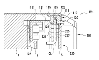
枠上部ヒンジ機構WH1は、外枠1の左上端角部に固定された外枠側ヒンジ金具110と、前枠2の左上端角部に固定された前枠側ヒンジ金具120とから構成される。
The frame upper hinge mechanism WH1 includes an outer frame side hinge fitting 110 fixed to the upper left corner of the
前枠側ヒンジ金具120は、前後に延びる平板状のヒンジプレート部121と、このヒンジプレート部121の先端部に上方に突出してカシメ固着された軸部123とを主体として構成される。ヒンジプレート部121の後端側には下向きに折り曲げられて前枠2の後面に沿って下方に延びる固定辺部122が形成され、ここに前枠側の位置決めピンと嵌合して前枠側ヒンジ金具120を位置決めするピン孔や、金具固定ネジを挿通させるネジ挿通孔が形成されている。
The front frame side hinge fitting 120 is mainly composed of a flat plate-like
軸部123は、ヒンジプレート部121から上方に突出する円柱状をなし、その上端に前枠2の閉鎖姿勢において斜め前後方向に延びるスリ割り状の割り溝125が形成されている(図3、図7等を参照)。具体的には、軸部123は、例えば直径がφ12〜20mm程度、ヒンジプレート部121上面からの突出高さが6〜12mm程度の円柱状をなし、上端に幅4〜6mm程度、深さ3〜5mm程度の割り溝125が軸部上端に形成されている。
The
割り溝125の前端側では、左右の溝壁面のうち一方(図7に示す前枠2の閉鎖姿勢において前側に位置する溝壁面)が溝幅外方に開き、外枠側ヒンジ金具110との係合を案内する導入壁面127が形成されている。また軸部123の下部には、前枠側ヒンジ金具120の下面側に開口して、後述する扉ヒンジ機構THのヒンジピン323を受容するピン受容穴128が形成されている。
On the front end side of the
前枠側ヒンジ金具120は、例えば板厚2.3〜3.2mm程度の鋼板を打ち抜き及び曲げ成形して形成したヒンジプレート部121に、切削加工により上記形状に形成された軸部123をカシメ固着することで一体に形成され、必要に応じてクロメート処理等の表面処理を施して構成される。そして固定辺部122に形成されたピン孔を前枠2の裏面側上端部に形成された位置決めピンに嵌合させることで前枠側ヒンジ金具120が位置決めされ、固定辺部122のピン挿通孔を通して金具固定ネジを締め込むことによりネジ締結されて、前枠側ヒンジ金具120が前枠2の左上端角部に位置決め固定される(図2を併せて参照)。
The front frame side hinge
前枠側ヒンジ金具120が前枠2に取り付けられると、ヒンジプレート部121が前枠2の上面に沿って前後に延びるとともに、その前端部が前枠2から幾分前方に突出して配設され、軸部123に形成された割り溝125が前枠2の前後面に対して斜め前後方向に延びて配設される。本実施例では、この割り溝125の形成角度を前枠2の前後面に対して30度の角度位置に設定した構成例を示している(図7及び図8を参照)。
When the front frame side hinge fitting 120 is attached to the
外枠側ヒンジ金具110は、前後に延びる平板状のヒンジプレート部111と、このヒンジプレート部の前端部に設けられ軸部123の外周面と係合する軸受部113、軸受部113と繋がって後方に延び後部が開放されたガイド部114、軸受部113の後方に位置してヒンジプレート部111に設けられ割り溝125の溝幅に合わせた外幅寸法で下向きに突出する保持突起115、などを主体として形成される。
The outer frame side hinge fitting 110 is connected to a flat plate-like
軸受部113は、ヒンジプレート部111の前端側の周辺が下向きに曲げ起こされて、下方に開く半円筒状に形成されており、円筒内周面の径が軸部123の外径よりもわずかに大きめに設定されている。軸受部113を形成する円筒状壁面に繋がって後方に延びる左右の側壁面のうち、右側の側壁面は軸部123の直径よりも幾分長く延びたのち後方部分が切り欠かれて右側方に開く開放部116が形成される一方、左側の側壁面は切り欠かれることなく左斜め後方に延び、軸部123を軸受部113に案内するガイド壁117が形成されている。
The bearing
ガイド部114は、上記右側壁面の後方に形成された開放部116と、左側方を覆うガイド壁117とによってヒンジプレート部111の下面側に形成され、開放部116から導入した軸部123を軸受部113に案内するように構成される。
The
保持突起115は、軸受部113の後方に位置してヒンジプレート部111の下面側に突出して設けられている。各図には、ヒンジプレート部111の一部を下向きに切り起こして舌片状の保持突起を形成した構成例を示しており、保持突起115の左右方向の中心位置が軸受部113の軸心を通って前後に延びる軸線上に設定され、軸受部113の円筒状壁面の内面と保持突起115の前面との対面間隔が、軸部123の直径よりもわずかに大きめの間隔を隔てて設定されるとともに、保持突起115の左右方向の幅が割り溝125の溝幅に合わせて溝幅よりもわずかに小さめに設定され、保持突起115の突出高さが割り溝125の溝底面に接触しない程度の高さに設定されている。
The holding
外枠側ヒンジ金具110は、例えば板厚2.3〜3.2mm程度の鋼板をプレス成形して形成され、必要に応じてクロメート処理等の表面処理を施して構成される。ヒンジプレート部111の後部には、外枠1の左上端角部に合わせて直角に曲げ成形された固定辺部が設けられており、この固定辺部を外枠1の左上端角部に突き当て配設することで外枠側ヒンジ金具110が位置決めされ、上枠杆及び左枠杆にリベット締結することで外枠1の左上端角部に固定される。
The outer frame side hinge fitting 110 is formed, for example, by press-molding a steel plate having a plate thickness of about 2.3 to 3.2 mm, and is subjected to surface treatment such as chromate treatment as necessary. At the rear part of the
こうして取り付けられた外枠側ヒンジ金具110と前枠側ヒンジ金具120とがヒンジ接続されると、図8に示すように、前枠2を前方に60度開放した角度位置(以下、便宜的に「着脱角度位置」という)において、前枠2とともに平面視時計廻りに回動した割り溝125の方向が前後方向となり、軸部123の外周面に摺接していた保持突起115が割り溝125の後方に位置整合して、軸部123と保持突起115との係合が解除される。このため、この着脱角度位置で前枠2を後方に傾動させたときに、割り溝125が保持突起115を受容して軸部123が軸受部113とガイド部114との間を移動し、外枠側ヒンジ金具110と前枠側ヒンジ金具120との係脱を行うことができる。また図8に示す前枠2の着脱角度位置から、前枠2を他の角度位置(閉鎖方向または開放方向)に揺動させた状態では、保持突起115が軸部123の外周面と係合して軸部123を軸受部113内に保持させ、前枠2が軸部123と軸受部113との嵌合軸CLを中心として揺動開閉可能に支持される。
When the outer frame side hinge fitting 110 and the front frame side hinge fitting 120 thus attached are hingedly connected, as shown in FIG. 8, the
なお、上記実施例では、保持突起115をヒンジプレート部111に切り起こし成形で形成した例を示したが、例えば、割り溝125の溝幅に合わせた外径のピン状の突起部材をヒンジプレート部111に下向きにカシメ固着し、あるいは割り溝125の溝幅に合わせた外面幅で下向きに突出する舌片状ないしブロック状の突起部材をヒンジプレート部111に溶着して保持突起を構成しても良い。
In the above embodiment, the holding
一方、枠下部ヒンジ機構WH2は、外枠1の左側縁下部に固定された外枠側ヒンジ金具210と、前枠2の左下端角部に固定された前枠側ヒンジ金具220とから構成される。
On the other hand, the frame lower hinge mechanism WH2 includes an outer frame side hinge fitting 210 fixed to the lower left edge of the
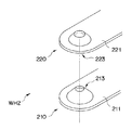
外枠側ヒンジ金具210は、前後に延びる平板状のヒンジプレート部211と、このヒンジプレート部211の先端部に上方に突出して成型された円錐状の係合凸部213とを主体として構成される。ヒンジプレート部211の後部は後方に延出されたうえ下向きに屈曲され、外枠1における幕板の背面及び左枠杆の内面に沿って延びる固定辺部が形成されている。
The outer frame side hinge fitting 210 is mainly composed of a flat
係合凸部213は、例えば係合凸部の最大外径(ヒンジプレート部211上面位置での外径)がφ15〜25mm程度、円錐面の傾斜角度が40〜60度程度に設定される。また係合凸部213の形成位置は、この外枠側ヒンジ金具210を外枠1に取り付けたときに、係合凸部213の中心軸線が、前述した枠上部ヒンジ機構WH1における嵌合軸CLの軸線上に配設されるように設定されている。
For example, the
前枠側ヒンジ金具220は、前後に延びる平板状のヒンジプレート部221と、このヒンジプレート部221の先端部に下方に開いて成型された円錐状の係合凹部223とを主体として構成される。係合凹部223は円錐状の内周面の傾斜角度が係合凸部213の外周面の傾斜角度と同一角度に設定される一方、係合凹部223の最大内径(ヒンジプレート部221下面位置での内径)が係合凸部の最大外径(ヒンジプレート部211上面位置での外径)よりも幾分小さめに設定されている。
The front frame side hinge fitting 220 is mainly composed of a flat
このため、係合凸部213と係合凹部223とを係合させたときに、係合凸部213の円錐外周面と係合凹部223の円錐内周面とが相互に面接触して共通の軸心まわりに相対摺動可能に連結されるとともに、上下のヒンジプレート部211,221の間に所定間隔が形成され、ヒンジプレート同士の直接接触による摺動抵抗が生じないようになっている(図10を参照)。
Therefore, when the engaging
ヒンジプレート部221の後部は後方に延出されたうえ上向きに折り曲げられて前枠2の後面に沿って上方に延びる固定辺部222が形成され、ここに前枠側の位置決めピンと嵌合して前枠側ヒンジ金具220を位置決めするピン孔や、金具固定ネジを挿通させるネジ挿通孔が形成されている。
The rear portion of the
外枠側ヒンジ金具210及び前枠側ヒンジ金具220は、例えば板厚2.3〜3.2mm程度の鋼板を、それぞれ所定の展開形状に打ち抜くとともに、ヒンジプレート部211,221の各先端側に、それぞれ係合凸部213及び係合凹部223をエンボス成型し、ヒンジプレート部の後部に固定辺部を曲げ成形することで各一体に形成され、必要に応じてクロメート処理等の表面処理を施して構成される。
For example, the outer frame side hinge fitting 210 and the front frame side hinge fitting 220 are each formed by punching a steel plate having a thickness of about 2.3 to 3.2 mm into a predetermined unfolded shape. Each of the engaging
そして、外枠側ヒンジ金具210は、固定辺部を幕板と左枠杆とが交わる外枠1の左下内周角部に突き当てて配設することで位置決めされ、左枠杆側の固定辺部をリベット締結し幕板側の固定辺部をネジ締結することで外枠側ヒンジ金具210が外枠1の左下側角部に位置決め固定される。また前枠側ヒンジ金具220は、固定辺部222に形成されたピン孔を前枠2の裏面側下端部に形成された位置決めピンに嵌合させることで位置決めされ、固定辺部のピン挿通孔を通して金具固定ネジを締め込むことによりネジ締結されて、前枠側ヒンジ金具220が前枠2の左下端角部に位置決め固定される(図2を参照)。
The outer frame side hinge fitting 210 is positioned by abutting the fixed side portion against the lower left inner corner of the
こうして外枠側ヒンジ金具210及び前枠側ヒンジ金具220がそれぞれ取り付けられると、ともに円錐状に成型された係合凸部213と係合凹部223との嵌合を利用して枠下部ヒンジ機構WH2が嵌脱自在に構成され、嵌合状態では相互に係合する円錐面の作用により前枠側ヒンジ金具220が係合凸部の中心軸まわりに回転摺動自在に配設され、これにより前枠2が外枠1に対して揺動開閉自在にヒンジ接続される。なお、係合凸部及び係合凹部は、相互に係合する円錐面を有していれば良く、例えば上端面が閉鎖した載頭円錐形状(断面視ハット状)であってもよい。
When the outer frame side hinge fitting 210 and the front frame side hinge fitting 220 are respectively attached in this way, the frame lower hinge mechanism WH2 is utilized by utilizing the fitting of the engagement
さて次に、以上のように構成される枠上部ヒンジ機構WH1及び枠下部ヒンジ機構WH2からなる枠ヒンジ機構WHの作用について説明する。 Next, the operation of the frame hinge mechanism WH composed of the frame upper hinge mechanism WH1 and the frame lower hinge mechanism WH2 configured as described above will be described.
まず、外枠1と前枠2とが分離された状態から上下のヒンジ機構WH1,WH2をヒンジ連結させるには、作業者は前枠2の左右側縁を把持して持ち上げ支持し、枠下部ヒンジ機構WH2に着目する。そして前枠2を幾分開いた角度姿勢で外枠側ヒンジ金具の係合凸部213に前枠側ヒンジ金具の係合凹部223を概略位置合わせし、係合凹部223を係合凸部213に覆い被せるようにして、外枠側ヒンジ金具210に前枠側ヒンジ金具220を嵌合接続させる。
First, in order to make the upper and lower hinge mechanisms WH1 and WH2 hinge-coupled from the state in which the
ここで、枠下部ヒンジ機構WH2では、嵌合接続すべき係合凸部213と係合凹部223とがともに円錐状に形成されている。このため、係合凸部213と係合凹部213との位置合わせは、両者の円錐面が部分的に係合する程度の概略的な位置合わせで良く、あとは円錐外周面と円錐内周面との案内作用により自動調心されて、相互の軸心が一致する方向に嵌合する。従って、前枠2に多くの遊技部品が組付けられて重量物となった遊技機本体を外枠1に連結させる場合のように、荷重を支持しながら微妙な位置合わせを行い難いような場合であっても、外枠側ヒンジ金具210と前枠側ヒンジ金具220とを簡単にヒンジ連結させることができる。
Here, in the frame lower hinge mechanism WH2, the engaging
こうして外枠側ヒンジ金具210と前枠側ヒンジ金具220とが係合されると、遊技機本体の荷重が外枠側ヒンジ金具210に支持され、この状態で前枠2を前後左右に傾動させることができるようになる。そこで、今度は枠上部ヒンジ機構WH1に着目し、枠下部ヒンジ金具WH2を支点として前枠2を傾動させ、前枠側ヒンジ金具120の軸部123を外枠側ヒンジ金具110の開放部116からガイド部114に進入させる。
When the outer frame side hinge fitting 210 and the front frame side hinge fitting 220 are thus engaged, the load of the gaming machine main body is supported by the outer frame side hinge fitting 210, and in this state, the
次いで図11(a)(b)に枠上部ヒンジ機構WH1の係合過程を示すように、ガイド部114に進入させた軸部123の外周面をガイド壁117に当接させ、前枠2を前方に15〜60度程度開いた角度姿勢で、軸部123をガイド壁117に沿って斜め前方に移動させる。すると軸部123の上端に形成された割り溝125が軸部とともにガイド壁117に沿って斜め前方に移動し、溝の前端側に保持突起115を受容する(図11(a)を参照)。ここで、割り溝125の前端側には、ガイド壁117側の溝壁面が溝幅の広がる方向に開いて導入壁面127が形成されており、(a)図からも明らかなように、前枠2の開放角度について厳密な角度位置の調整を要することなく、広い角度範囲で保持突起115を受容し、受容した保持突起を割り溝125の中央に向けて案内するようになっている。
Next, as shown in FIGS. 11 (a) and 11 (b), the engagement process of the frame upper hinge mechanism WH1 is brought into contact with the outer peripheral surface of the
保持突起115が導入壁面127の後部(割り溝125の狭小部)まで進入したら、前枠の開き角を前述した着脱角度位置に合わせ、この角度位置で前枠2を前方に傾動させる。すると、図11(b)に示すように、割り溝125が保持突起115を受容しながら前方に移動するとともに、軸部123が左右の側壁に案内されながら前方に移動し、図8に示したように、軸部123が軸受部113内に嵌入する。
When the holding
ここで、前枠2を前方に開いた状態では、遊技機本体の荷重が、枠下部ヒンジ機構WH2を支点として前枠2を前方に傾動させる方向、すなわち軸部213が軸受部113の円筒支持面に押し付けられる方向にモーメントとして作用する。このため、軸部123が軸受部113内に嵌入すると、モーメントに抗して前枠2を後方に傾動させない限り、軸部213と軸受部113との嵌合状態が保持される。
Here, in a state where the
そして、軸部123と軸受部とが嵌合した状態で、前枠2を着脱角度位置から他の角度位置(閉鎖方向または開放方向)に揺動させると、軸部123の前方の外周面が軸受部113の円筒状の内周面と係合し、軸部123の後方の外周面が保持突起115の前面と係合して軸部123を軸受部113内に保持させ、外枠側ヒンジ金具110と前枠側ヒンジ金具120のヒンジ接続が外れないように規制する(図7を参照)。嵌合状態における軸部123の上面とヒンジプレート部111の下面との隙間は、枠下部ヒンジ機構WH2における係合凸部213と係合凹部223の嵌合高さよりも小さく設定されており、上下の枠ヒンジ機構のヒンジ接続が外れないようになっている(図9及び図10を参照)。
Then, when the
こうして上下の枠ヒンジ機構WH1,WH2をヒンジ接続させた状態では、枠下部ヒンジ機構WH2の円錐状の係合凸部213と係合凹部223との嵌合により前枠2を含む遊技機本体の荷重が支持され、枠上部ヒンジ機構WH1の軸受部113と軸部123との嵌合及び保持突起115の存在により前後左右方向への傾動が規制されて、前枠2が上下の枠ヒンジ機構WH1,WH2の共通した嵌合軸CL廻りに回動自在に支持される。
In a state where the upper and lower frame hinge mechanisms WH1 and WH2 are hinge-connected in this way, the gaming machine main body including the
一方、枠ヒンジ機構WHのヒンジ接続を解除して前枠2を外枠1から分離させる場合には、上記連結時と逆の手順を行えば良い。すなわち、前枠2を開放して開放角度位置に設定し(図8)、前枠2の上部を後方に傾動させて軸部123をガイド部114の後方に移動させ(図11(b))、保持突起115と割り溝125との係合を解除させた状態で枠下部ヒンジ機構WH2を支点として前枠2を右傾させ、軸部123を開放部116から導出して外枠側ヒンジ金具110と前枠側ヒンジ金具120との係合を解除する。そして前枠2を斜め上方に引き上げて係合凸部213から係合凹部223を浮き上がらせ、枠下部ヒンジ機構の外枠側ヒンジ金具210と前枠側ヒンジ金具120との係合を解除する。これにより上下の枠ヒンジ機構WH1,WH2のヒンジ接続が解除され、外枠1と前枠2とが分離される。
On the other hand, when the hinge connection of the frame hinge mechanism WH is released and the
従って、以上説明したような枠上部ヒンジ機構WH1によれば、軸部123の上端に割り溝125を形成し、外枠側ヒンジ金具に軸受部113と保持突起115を形成する簡明な構成で前枠2を容易に着脱でき、かつ前枠2を閉止させた状態ではヒンジ接続を強固に保持させるヒンジ機構を提供することができる。また、外枠側ヒンジ金具のヒンジプレート部111を下向きに切り起こして保持突起115を形成することにより、外枠側ヒンジ金具110のプレス成型時に保持突起115を一体的に形成することができ、部品点数を増加させることなく、極めて簡明な構成で上記効果を備えたヒンジ機構を得ることができる。
Therefore, according to the frame upper part hinge mechanism WH1 as described above, the front end of the
また枠下部ヒンジ機構WH2によれば、係合凸部213と係合凹部223とが、ともに円錐状に形成されているため、たとえ前枠2が大型かつ重量物であり微妙な位置合わせが行い難いような場合であっても、円錐外周面と円錐内周面との案内作用及び自動調心作用を利用して、外枠側ヒンジ金具210と前枠側ヒンジ金具220とを簡単にヒンジ接続させることができる。また、従来のヒンジ機構のように軸ピンにヒンジ金具の端部をぶつけて曲げてしまったり、軸ピンに服や体を引っ掛けて傷つけたり遊技機を転倒させてしまうようなこともなく、軸ピンの突出に起因する問題を抑制することができる。さらに、係合凸部213及び係合凹部223が各ヒンジプレート部に成型されているため、ヒンジ金具のプレス成型時に一体的に形成することができ、部品点数を削減し、極めて簡明な構成で上記効果を備えたヒンジ機構を提供することができる。
Further, according to the frame lower hinge mechanism WH2, since the engaging
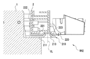
さて次に、前枠2に対してガラス扉5を開閉自在に支持する扉ヒンジ機構THについて、既に参照した図3、図6〜図9と、図12とを参照しながら説明する。ガラス扉ヒンジ機構THは、扉上部ヒンジ機構TH1と扉下部ヒンジ機構TH2とからなり、ガラス扉5の左端上下に設けられている。なお、図12は、図1中に付記するXII−XII矢視方向の断面図であり、扉下部ヒンジ機構TH2の側断面図である。
Next, the door hinge mechanism TH that supports the
扉下部ヒンジ機構TH2は、前枠2の左側縁中間部に固定された前枠側ヒンジ金具410と、ガラス扉5の左下端角部に固定された扉側ヒンジ金具420とから構成される。
The door lower hinge mechanism TH2 includes a front frame side hinge fitting 410 fixed to the middle portion of the left edge of the
前枠側ヒンジ金具410は、前後に延びる平板状のヒンジプレート部411と、このヒンジプレート411の先端部に上方に突出してカシメ固着されたヒンジピン413とを主体として構成される。ヒンジプレート部411の後部は下向きに屈曲されて前枠2の前面に沿って延びる固定辺部412が形成され、ここに前枠側の位置決めピンと嵌合して前枠側ヒンジ金具410を位置決めするピン孔や、金具固定ネジを挿通させるネジ挿通孔が形成されている。
The front frame side hinge fitting 410 is mainly composed of a flat plate-like
ヒンジピン413の配設位置は、固定辺部412を前枠前面に位置決め固定したときに、ヒンジピン413の中心軸線が、前述した枠ヒンジ機構WHの嵌合軸CLと同一軸上になるように設定されている。ヒンジピン413の上端部は先細テーパ状に面取りされて扉側ヒンジ金具のピン受容孔423との嵌合を容易化するとともに、ヒンジピン413の基端部には扉側ヒンジ金具のヒンジプレート部421を支持する円環状の支持面が形成されており、ガラス扉5を開閉する際の摺動抵抗を低減した構成になっている。
The position of the
前枠側ヒンジ金具410は、例えば板厚1.6〜2.3mm程度の鋼板を、所定の展開形状に打ち抜き固定辺部を曲げ成形するとともに、ヒンジプレート部411の先端側に直径φ3〜5mm程度、突出高さ5〜8mm程度のヒンジピン413をカシメ固着し、必要に応じてクロメート処理等の表面処理を施して構成される。なお、本実施例では、前枠側ヒンジ金具410が球皿ユニット6の上部ヒンジ金具を兼ねた構成となっており、ヒンジピンをヒンジプレート部411の上下に突出させた形態になっている。
For example, the front frame side hinge fitting 410 is formed by punching a steel plate having a plate thickness of about 1.6 to 2.3 mm into a predetermined unfolded shape, bending the fixed side portion, and forming a diameter φ3 to 5 mm on the distal end side of the
扉側ヒンジ金具420は、前後に延びる平板状のヒンジプレート部421と、このヒンジプレート421の先端部に、ヒンジピン413の軸径よりもわずかに大きめの内径で穿設されたピン受容孔423とを主体として構成される。ヒンジプレート部421の後部は上向きに折り曲げられてガラス扉5の背面に沿って上方に延び、ガラス窓の周囲を囲む窓枠フレームの左枠杆部を形成する。左枠杆部にはガラス扉背面の位置決めピンと嵌合して扉側ヒンジ金具420を位置決めするピン孔や、金具固定ネジを挿通させるネジ挿通孔が形成されている。
The door-side hinge fitting 420 includes a flat plate-like
この左枠杆部の上端に扉上部ヒンジ機構TH1の扉側ヒンジ金具320が設けられている。扉上部ヒンジ機構TH1は、前述した前枠側ヒンジ金具120と、ガラス扉5の左上端角部に設けられた扉側ヒンジ金具320とから構成される。すなわち、パチンコ機PMでは、前枠側ヒンジ金具120が、枠上部ヒンジ機構のYH1の前枠側ヒンジ金具と、扉上部ヒンジ機構THの前枠側ヒンジ金具との両方の機能を併せ持った構成になっている。
A door side hinge fitting 320 of the door upper hinge mechanism TH1 is provided at the upper end of the left frame collar. The door upper hinge mechanism TH1 includes the above-described front frame side hinge fitting 120 and the door side hinge fitting 320 provided at the upper left corner of the
扉側ヒンジ金具320は、上下平行に前方に延びるピン支持部321と、このピン支持部321に上下に摺動変位可能に配設されたピン部材323、詳細図示省略するがピン部材323を上方に付勢するコイルバネ、ピン部材323に嵌着されて上方に付勢されたピン部材323の上端位置を規定するEリング325などから構成される。
The door-side hinge fitting 320 includes a
ピン支持部321は、前枠側ヒンジ金具120におけるヒンジプレート部121の直下に位置する前記左枠杆部の上端部が前方にコの字状に折り曲げられて形成されており、上下の支持辺には、扉下部ヒンジ機構TH2のピン受容孔423と同軸上に位置して、ヒンジピン323の軸径よりもわずかに大きめの内径のピン支持孔が穿設されている。ピン部材323は上下に延びる係合軸部と、この係合軸部の下端がL字状に折り曲げられて形成された操作軸部とからなり、係合軸部の上部にはEリング325を受容するリング溝が形成されている。ピン部材323は、例えば直径φ3〜5mm程度のアルミ合金やステンレス等の金属線材を加工成形して構成される。
The
ピン部材323を上方に付勢するコイルバネは、例えばコの字状のピン支持部321の内側に配設されてEリング325を上方に付勢する圧縮コイルバネやピン支持部321とヒンジピンの操作軸部との間に張り渡されて操作軸部を上方に付勢する引っ張りコイルバネなど公知の付勢手段を用いることができる。これによりピン支持部321に上下に摺動自在に支持されたピン部材323が常時上方に付勢され、Eリング325がピン支持部321の下面に当接する上動端部位置に配設される。なお、ピン支持部321にはEリング325の下動端部位置を規定してピン部材323の抜け落ちを防止する下動規制片が設けられている(不図示)。
The coil spring that biases the
扉側ヒンジ金具320は、ピン部材323の操作軸部を迂回してガラス扉5の背面に沿って下方に延び、前述した窓枠フレームの左枠杆部を形成する。すなわち、上下の扉側ヒンジ金具320,420が窓枠フレームの左枠杆部に設けられ、窓枠フレームをガラス扉5の背面側に突出成型された位置決めピンに嵌合させてネジ固定することで、上下の扉側ヒンジ金具がガラス扉の左縁上下に配設されるようになっている。
The door-side hinge fitting 320 bypasses the operation shaft portion of the
一方、前枠側ヒンジ金具120には、ピン部材323を受容するピン受容穴128が形成されている。ピン受容穴128は、軸部123の軸心(すなわち嵌合軸CL上)に位置し前枠側ヒンジ金具120の下面側に開口して形成されており、その内径はピン部材323の外径よりも幾分大きく、穴深さは上動端部位置にあるピン部材323の上端面の配設位置よりも幾分深めに設定されている。
On the other hand, the front frame side hinge fitting 120 is formed with a
このように構成される上下の扉ヒンジ機構TH1,TH2をヒンジ連結させるには、ガラス扉5の左右側縁を把持して持ち上げ支持し、まず扉下部ヒンジ機構TH2に着目する。そしてガラス扉5を幾分開いた角度姿勢で、扉側ヒンジ金具のピン受容孔423を前枠側ヒンジ金具のヒンジピン413に位置合わせして嵌合させ、前枠側ヒンジ金具410と扉側ヒンジ金具420とをヒンジ接続させる。
In order to connect the upper and lower door hinge mechanisms TH1 and TH2 configured as described above, the left and right side edges of the
扉下部ヒンジ機構TH2が連結されたら、今度は扉上部ヒンジ機構TH1に着目し、ピン部材323の操作軸部に指を掛けて押し下げ、係合軸部がピン支持部321の上面から大きく突出しない下動端部位置まで下動させる。次いでガラス扉5の上端側を傾動させて扉側ヒンジ金具320を前枠側ヒンジ金具120の直下に位置させ、操作軸部への下向きの操作力を解放する。そしてピン部材323の係合軸部とピン受容穴128とを位置合わせしてピン部材323の先端部をピン受容穴128に嵌入させる。
When the door lower hinge mechanism TH2 is connected, this time, paying attention to the door upper hinge mechanism TH1, put the finger on the operation shaft portion of the
ここで、ピン受容穴128が軸部123の軸心に形成されているため、ピン受容穴128の穴位置を外観から容易に想定し得るとともに、ピン部材323の先端とピン受容穴128の開口縁部にはともに円錐状の案内面が形成されており、ピン部材323を上方に付勢するコイルバネの作用と相まって、ピン部材323とピン受容穴128とを容易に嵌合させ得る構成になっている。
Here, since the
そして、ピン部材323の先端部がピン受容穴128に嵌入すると、ピン部材323はコイルバネのバネ力により上方に付勢されてEリング325がピン支持部321の下面に当接した上動端部位置に配設され、ピン部材323の先端部がピン受容穴128の内部に所定の嵌合深さを持って収容保持される。嵌合状態におけるピン支持部321の上面とヒンジプレート部121の下面との隙間は、扉下部ヒンジ機構TH2におけるヒンジピン413の突出高さよりも小さく設定されており、ガラス扉5を上方に持ち上げても上下の扉ヒンジ機構の接続が外れないようになっている(図9及び図12を参照)。
When the tip of the
こうして上下の扉ヒンジ機構TH1,TH2がヒンジ接続された状態では、枠下部ヒンジ機構TH2のヒンジピン413とピン受容孔423との嵌合によりガラス扉5の荷重が支持され、扉上部ヒンジ機構TH1のピン部材323とピン受容穴128との嵌合により前後左右方向への傾動が規制されて、ガラス扉5が上下の扉ヒンジ機構TH1,TH2の嵌合軸でありかつ前述した上下の枠ヒンジ機構WH1,WH2の嵌合軸でもある共通した嵌合軸CL廻りに回動自在に支持される。なお、扉ヒンジ機構THのヒンジ接続を解除してガラス扉5を前枠2から取り外す場合には、上記連結時と逆の手順を行えば良く、この操作は当業者であれば容易に理解することができるため、ここでは説明を省略する。
When the upper and lower door hinge mechanisms TH1 and TH2 are hinge-connected in this way, the load of the
従って、以上説明したような扉ヒンジ機構THによれば、扉側ヒンジ金具320と前枠側ヒンジ金具120とをヒンジ接続させたときに、ピン部材323の先端部が前枠側ヒンジ金具の軸部123の内部に収容され、ピン部材323の頭部が露出して配設されるようなことがない。従って扉ヒンジ機構THに対する不正行為を効果的に抑制することができる。またピン部材323の先端部が軸部123の内部に収容されるため、枠ヒンジ機構WHを連結・分離させる際に障害になるようなことがなく、良好な作業性を確保することができる。さらに、ピン受容穴128が前枠側ヒンジ金具120の軸部を利用して形成されているため、扉ヒンジ機構THを簡明且つ低廉に構成することができる。
Therefore, according to the door hinge mechanism TH as described above, when the door side hinge fitting 320 and the front frame side hinge fitting 120 are hinge-connected, the tip of the
CL 嵌合軸
PM パチンコ機
TH 扉ヒンジ機構
TH1 扉上部ヒンジ機構
TH2 扉下部ヒンジ機構
WH 枠ヒンジ機構
WH1 枠上部ヒンジ機構
WH2 枠下部ヒンジ機構
1 外枠
2 前枠
5 ガラス扉
110 外枠側ヒンジ金具
111 ヒンジプレート部
113 軸受部
114 ガイド部
115 保持突起
120 前枠側ヒンジ金具
121 ヒンジプレート部
123 軸部
125 割り溝
127 導入壁面
128 ピン受容穴
210 外枠側ヒンジ金具
211 ヒンジプレート部
213 係合凸部
220 前枠側ヒンジ金具
221 ヒンジプレート部
223 係合凹部
320 扉側ヒンジ金具
323 ピン部材
410 前枠側ヒンジ金具
411 ヒンジプレート部
413 ヒンジピン
420 扉側ヒンジ金具
421 ヒンジプレート部
423 ピン受容孔
CL Fitting shaft PM Pachinko machine TH Door hinge mechanism TH1 Door upper hinge mechanism TH2 Door lower hinge mechanism WH Frame hinge mechanism WH1 Frame upper hinge mechanism WH2 Frame
Claims (1)
前記上下一対の第1ヒンジ機構のうちの上方に位置する第1ヒンジ機構は、前記第1開閉部材の側部に固定されて前後に延びる開閉側板状部および前記開閉側板状部に上下方向に延びて固着された軸部を有して構成される開閉側ヒンジ部材と、前記ベース部材の側部に固定されて前後に延びるベース側板状部および前記ベース側板状部に設けられ前記軸部と係合する軸受部を有して構成されるベース側ヒンジ部材とからなり、
前記軸部が前記軸受部と係合して前記軸部の中心を通る上下に延びる嵌合軸を中心として互いに回転可能に係合することにより、前記ベース部材に対して前記第1開閉部材が前記嵌合軸を中心として揺動開閉自在にヒンジ接続されるように構成されており、
前記上下一対の第2ヒンジ機構のうちの上方に位置する第2ヒンジ機構は、前記第2開閉部材の側部上部に上下にスライド変位可能に軸支されたピン部材と、前記開閉側ヒンジ部材に前記軸部内に延びて形成されるとともに前記ピン部材を受容してこれと回転可能に係合可能なピン受容穴とからなり、
前記ピン部材を前記ピン受容穴に受容してこれと係合することにより、前記第1開閉部材に対して前記第2開閉部材が揺動開閉自在にヒンジ接続されるように構成されており、
前記ピン部材の先端に円錐状の先端案内面を有し、前記ピン受容穴の開口縁部に円錐状に拡がる開口案内面を有することを特徴とする遊技機のヒンジ機構。 A first opening / closing mechanism hinged to the front surface of the base member so as to be swingable open / closed by a base member and a pair of upper and lower first hinge mechanisms provided on the front surface of the base member and provided on one of the left and right sides. And a pair of upper and lower second hinge mechanisms provided on the front side of the member and the first opening / closing member and swingable with respect to the first opening / closing member. A hinge mechanism of a gaming machine comprising a second opening / closing member connected to a hinge,
The first hinge mechanism located above the pair of upper and lower first hinge mechanisms is fixed to the side portion of the first opening / closing member and extends in the vertical direction to the opening / closing side plate-like portion and the opening / closing side plate-like portion. An open / close hinge member configured to have a shaft portion extending and fixed, a base side plate-like portion fixed to a side portion of the base member and extending in the front-rear direction, and the shaft portion provided in the base-side plate-like portion; A base side hinge member configured to have a bearing portion to be engaged,
The first opening / closing member is engaged with the base member by engaging the shaft portion with the bearing portion so as to be rotatable around a fitting shaft extending vertically through the center of the shaft portion. It is configured to be hinged so that it can swing open and close around the fitting shaft,
The second hinge mechanism located above the pair of upper and lower second hinge mechanisms includes a pin member pivotally supported on the upper side portion of the second opening / closing member so as to be slidable up and down, and the opening / closing hinge member And a pin receiving hole formed to extend into the shaft portion and receive the pin member and rotatably engage with the pin member,
The pin member is received in the pin receiving hole and engaged therewith, so that the second opening / closing member is hingedly connected to the first opening / closing member so as to be swingable and openable.
A hinge mechanism for a gaming machine comprising: a conical tip guide surface at a tip of the pin member; and an opening guide surface extending in a conical shape at an opening edge of the pin receiving hole.
Priority Applications (1)
| Application Number | Priority Date | Filing Date | Title |
|---|---|---|---|
| JP2011110802A JP2011177560A (en) | 2011-05-17 | 2011-05-17 | Hinge mechanism of game machine |
Applications Claiming Priority (1)
| Application Number | Priority Date | Filing Date | Title |
|---|---|---|---|
| JP2011110802A JP2011177560A (en) | 2011-05-17 | 2011-05-17 | Hinge mechanism of game machine |
Related Parent Applications (1)
| Application Number | Title | Priority Date | Filing Date |
|---|---|---|---|
| JP2006004617A Division JP4895002B2 (en) | 2006-01-12 | 2006-01-12 | Hinge mechanism of gaming machine |
Publications (2)
| Publication Number | Publication Date |
|---|---|
| JP2011177560A true JP2011177560A (en) | 2011-09-15 |
| JP2011177560A5 JP2011177560A5 (en) | 2012-03-08 |
Family
ID=44689714
Family Applications (1)
| Application Number | Title | Priority Date | Filing Date |
|---|---|---|---|
| JP2011110802A Pending JP2011177560A (en) | 2011-05-17 | 2011-05-17 | Hinge mechanism of game machine |
Country Status (1)
| Country | Link |
|---|---|
| JP (1) | JP2011177560A (en) |
Citations (3)
| Publication number | Priority date | Publication date | Assignee | Title |
|---|---|---|---|---|
| JP2003220254A (en) * | 2002-01-30 | 2003-08-05 | Moriso:Kk | Pachinko game machine |
| JP2004194727A (en) * | 2002-12-16 | 2004-07-15 | Heiwa Corp | Game machine |
| JP2006223752A (en) * | 2005-02-21 | 2006-08-31 | Kyoraku Sangyo | Hinge structure in game machine |
-
2011
- 2011-05-17 JP JP2011110802A patent/JP2011177560A/en active Pending
Patent Citations (3)
| Publication number | Priority date | Publication date | Assignee | Title |
|---|---|---|---|---|
| JP2003220254A (en) * | 2002-01-30 | 2003-08-05 | Moriso:Kk | Pachinko game machine |
| JP2004194727A (en) * | 2002-12-16 | 2004-07-15 | Heiwa Corp | Game machine |
| JP2006223752A (en) * | 2005-02-21 | 2006-08-31 | Kyoraku Sangyo | Hinge structure in game machine |
Similar Documents
| Publication | Publication Date | Title |
|---|---|---|
| JP4895001B2 (en) | Hinge mechanism of gaming machine | |
| JP4895002B2 (en) | Hinge mechanism of gaming machine | |
| JP5137044B2 (en) | Hinge mechanism of gaming machine | |
| JP2011177560A (en) | Hinge mechanism of game machine | |
| JP5078043B2 (en) | Hinge mechanism of gaming machine | |
| JP4521874B2 (en) | Top hinge structure of gaming machine | |
| JP2006223752A (en) | Hinge structure in game machine | |
| JP4092412B2 (en) | Inner frame mounting hinge | |
| JP2004016251A (en) | Securely holding mechanism for game board | |
| JP4060056B2 (en) | Hinges for gaming machines | |
| JP5023278B2 (en) | Hinge structure of gaming machine | |
| JP5403559B2 (en) | Hinge mechanism of gaming machine | |
| JP2011231984A (en) | High-frequency heating cooker | |
| JP2001259195A (en) | Hinge mechanism of pachinko game machine | |
| JP2003205152A (en) | Hinge device for game machine | |
| JP2005000379A (en) | Game machine | |
| JP2009045238A (en) | Game machine | |
| JP4846287B2 (en) | Hinge device for pachinko machine | |
| JPH1176552A (en) | Pachinko game machine | |
| JP3895442B2 (en) | Ball pan for ball tray in pachinko machine | |
| JP2005021616A (en) | Pachinko game machine | |
| JP2011167311A (en) | Pinball game machine | |
| JP4879562B2 (en) | Hinge device for pachinko machine | |
| JP2011036366A (en) | Hinge device of game machine | |
| JP2002331135A (en) | Hinge device for game machine frame body |
Legal Events
| Date | Code | Title | Description |
|---|---|---|---|
| A521 | Written amendment |
Effective date: 20120124 Free format text: JAPANESE INTERMEDIATE CODE: A523 |
|
| A131 | Notification of reasons for refusal |
Free format text: JAPANESE INTERMEDIATE CODE: A131 Effective date: 20120525 |
|
| A521 | Written amendment |
Free format text: JAPANESE INTERMEDIATE CODE: A523 Effective date: 20120710 |
|
| A02 | Decision of refusal |
Effective date: 20120803 Free format text: JAPANESE INTERMEDIATE CODE: A02 |
|
| A521 | Written amendment |
Effective date: 20121010 Free format text: JAPANESE INTERMEDIATE CODE: A523 |
|
| A911 | Transfer of reconsideration by examiner before appeal (zenchi) |
Free format text: JAPANESE INTERMEDIATE CODE: A911 Effective date: 20121018 |
|
| A912 | Removal of reconsideration by examiner before appeal (zenchi) |
Effective date: 20121116 Free format text: JAPANESE INTERMEDIATE CODE: A912 |