JP2011164237A - Imaging lens - Google Patents
Imaging lens Download PDFInfo
- Publication number
- JP2011164237A JP2011164237A JP2010025008A JP2010025008A JP2011164237A JP 2011164237 A JP2011164237 A JP 2011164237A JP 2010025008 A JP2010025008 A JP 2010025008A JP 2010025008 A JP2010025008 A JP 2010025008A JP 2011164237 A JP2011164237 A JP 2011164237A
- Authority
- JP
- Japan
- Prior art keywords
- lens
- refractive power
- object side
- imaging
- imaging lens
- Prior art date
- Legal status (The legal status is an assumption and is not a legal conclusion. Google has not performed a legal analysis and makes no representation as to the accuracy of the status listed.)
- Pending
Links
Images


Landscapes
- Lenses (AREA)
Abstract
Description
本発明は、監視用カメラや車載用カメラ等、固体撮像素子を備えた撮像装置に用いられる単焦点の広角撮像レンズに関する。 The present invention relates to a single-focus wide-angle imaging lens used for an imaging apparatus including a solid-state imaging device, such as a monitoring camera or an in-vehicle camera.
監視用カメラや車載用カメラに用いられる撮像レンズには、広画角を確保しながら画面全域で結像性能が良いことが要求される。また、搭載スペースが限られることが多いことなどから小型で軽量であることが要求される。 Imaging lenses used for surveillance cameras and in-vehicle cameras are required to have good imaging performance over the entire screen while ensuring a wide angle of view. In addition, since the mounting space is often limited, it is required to be small and lightweight.
これらの要望に対応し得る可能性がある単焦点の広角撮像レンズとして、下記の特許文献1、2が提案されている。しかしながら、この特許文献1、2に記載される単焦点レンズでは、最小厚みと最大厚みの比が大きいため、射出成形において金型内で溶融樹脂の流れが合流して融着した部分に細い線つまりウェルドラインの発生の可能性があった。また、第1レンズの有効径が大きく、小型化を難しくしていた。
The following
本発明は、上記の点に鑑みて成されたものであり、目的とするのは、金型内で溶融樹脂が合流して発生するウェルドといった不良を抑え、4枚構成によって高い光学性能を持ちつつ、レンズの形状、非球面の形状等を適切に設定することにより小型、薄型の広角撮像レンズを提供することである。 The present invention has been made in view of the above points, and an object of the present invention is to suppress defects such as welds generated by the fusion of molten resin in a mold and to have high optical performance by a four-sheet configuration. On the other hand, it is to provide a small and thin wide-angle imaging lens by appropriately setting the shape of the lens, the shape of the aspherical surface and the like.
上記目的を達成するため本発明のレンズは、物体側から順に、物体側に凸面を向けた負の屈折力を有するメニスカスレンズである第1レンズと、像側に凹面を向けた負の屈折力を有する第2レンズと、球面で、物体側に凸面を向けた正の屈折力を有する第3レンズと、開口絞りと、像側に凸面を向けた正の屈折力を有し、少なくとも1面が非球面である第4レンズとを配置し、下記条件式(1)、(2)を満たすことを特徴とする撮像レンズ。
d2/d1≦2 … (1)
d4/d3≦2 … (2)
但し、d1は第2レンズの最小厚、d2は第2レンズの最大厚、d3は第4レンズの最小厚、d4は第4レンズの最大厚である。
In order to achieve the above object, the lens of the present invention includes, in order from the object side, a first lens that is a meniscus lens having a negative refractive power with a convex surface facing the object side, and a negative refractive power with a concave surface facing the image side. A second lens having a spherical surface, a third lens having a positive refractive power with a convex surface facing the object side, an aperture stop, and a positive refractive power with a convex surface facing the image side, and at least one surface And an aspherical fourth lens, and satisfy the following conditional expressions (1) and (2).
d2 / d1 ≦ 2 (1)
d4 / d3 ≦ 2 (2)
However, d1 is the minimum thickness of the second lens, d2 is the maximum thickness of the second lens, d3 is the minimum thickness of the fourth lens, and d4 is the maximum thickness of the fourth lens.
好ましくは前記第1レンズを構成する材料のd線に対するアッベ数を40以上、前記第2レンズを構成する材料のd線に対するアッベ数を50以上、前記第3レンズを構成する材料のd線に対するアッベ数を40以下、前記第4レンズを構成する材料のd線に対するアッベ数を50以上に、それぞれ設定されることを特徴とする。各レンズの材料をこのような条件を満たすように選択することで、色収差の補正を適切に行うことができる。 Preferably, the Abbe number for the d-line of the material constituting the first lens is 40 or more, the Abbe number for the d-line of the material constituting the second lens is 50 or more, and the d-line of the material constituting the third lens The Abbe number is set to 40 or less, and the Abbe number for the d-line of the material constituting the fourth lens is set to 50 or more. By selecting the material of each lens so as to satisfy such conditions, chromatic aberration can be corrected appropriately.
更に好ましくは、下記条件式(3)を満足することを特徴とする。
a1/y≦2.1 …(3)
但し、a1は第1レンズのアパーチャー径、yは像高である。
More preferably, the following conditional expression (3) is satisfied.
a1 / y ≦ 2.1 (3)
Here, a1 is the aperture diameter of the first lens, and y is the image height.
更に好ましくは、下記条件式(4)〜(7)を満足することを特徴とする。
−5≦f1/f≦−2 … (4)
−5≦f2/f≦ −3 … (5)
3.0≦f3/f≦ 5.0 … (6)
0.5≦f4/f≦ 2.5 … (7)
但し、f1は第1レンズの焦点距離、f2は第2レンズの焦点距離、f3は第3レンズの焦点距離、f4は第4レンズの焦点距離である。
More preferably, the following conditional expressions (4) to (7) are satisfied.
−5 ≦ f1 / f ≦ −2 (4)
−5 ≦ f2 / f ≦ −3 (5)
3.0 ≦ f3 / f ≦ 5.0 (6)
0.5 ≦ f4 / f ≦ 2.5 (7)
Here, f1 is the focal length of the first lens, f2 is the focal length of the second lens, f3 is the focal length of the third lens, and f4 is the focal length of the fourth lens.
本発明によれば、最大厚みと最小厚みの比を制限することでウェルドといった不良を抑えることができる。また、第1レンズのアパーチャー径を小さくすることにより小型でかつ諸収差が良好に補正された広角撮像レンズを提供することができる。 According to the present invention, defects such as welds can be suppressed by limiting the ratio between the maximum thickness and the minimum thickness. In addition, by reducing the aperture diameter of the first lens, it is possible to provide a small-angle wide-angle imaging lens in which various aberrations are favorably corrected.
以下、図面を参照しながら、本発明の実施形態を詳細に説明する。
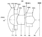
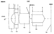
図1に実施の形態のレンズ構成をそれぞれ光学断面で示す。これらの実施形態は物体側から順に、第1レンズ110、第2レンズ120、第3レンズ130、開口絞り140、第4レンズ150、結像面160を有するCCD(Charge Coupled Device)やCMOS(Complementary Mental-Oxide Semiconductor device)等の撮像素子が配置される4枚構成の単焦点レンズ100である。
Hereinafter, embodiments of the present invention will be described in detail with reference to the drawings.
FIG. 1 shows the lens configuration of the embodiment in an optical section. In these embodiments, in order from the object side, a CCD (Charge Coupled Device) or a CMOS (Complementary) having a
本発明を実施した撮像レンズで好ましくは、条件式(1)、(2)を満足するように構成される。
d2/d1≦2 … (1)
d4/d3≦2 … (2)
但し、d1は第2レンズの最小厚、d2は第2レンズの最大厚、d3は第4レンズの最小厚、d4は第4レンズの最大厚である。
(1)、(2)の上限値を超えると、最小厚みと最大厚みの比が大きいために、射出成形において金型内で溶融樹脂の流れが合流して融着した部分に細い線つまりウェルドラインの発生の可能性があり、そのために製造が難しくなる。
The imaging lens embodying the present invention is preferably configured to satisfy conditional expressions (1) and (2).
d2 / d1 ≦ 2 (1)
d4 / d3 ≦ 2 (2)
However, d1 is the minimum thickness of the second lens, d2 is the maximum thickness of the second lens, d3 is the minimum thickness of the fourth lens, and d4 is the maximum thickness of the fourth lens.
When the upper limit of (1) and (2) is exceeded, the ratio of the minimum thickness to the maximum thickness is large. Lines can be generated, which makes manufacturing difficult.
本発明を実施した撮像レンズで4枚のレンズは、物体側から順に、物体側に凸面を向けて負の屈折力を有することで広い画角を得るのに有利に働くメニスカスレンズである第1レンズ110と、物体側に凹面を向けることで小型化に有利で製造難易度も低くした負の屈折力を有するメニスカスレンズである第2レンズ120と、物体側に凸面を向けて正の屈折力を有することで収差補正を容易にした第3レンズ130と、開口絞り140と像側に凸面を向けて正の屈折力を有することで結像面への入射角度を小さくした第4レンズ150のように配列されている。
The four lenses in the imaging lens embodying the present invention are meniscus lenses that are advantageous for obtaining a wide angle of view by having a negative refractive power with a convex surface facing the object side in order from the object side. The
撮像レンズ100において、物体側OBJSより入射した光は、第1レンズ110の物体側R1面1、像面側R2面2、第2レンズ120の物体側R3面3、像面側R4面4、第3レンズ130の物体側R5面5、像面側R6面6、開口絞り部140の面7、第4レンズ150の物体側R7面8、像面側R8面9、を順次通過し撮像素子160へと集光される。
In the
第2レンズ120と第4レンズ150が樹脂材料で形成されることにより、軽量化や低コスト化が実現できるとともに、非球面形状の作製が容易となる。これらのレンズはそれぞれ少なくとも1面の非球面形状が形成される。非球面形状を持つことにより、収差補正が容易となり、小型でありながら良好な解像性能を得ることが可能となる。
By forming the
また、樹脂材料で形成される第2レンズ120と第4レンズ150のパワーの組み合わせを負、正としていることで屈折率の温度特性の相殺が可能となっている。一般に樹脂材料は硝子材料に比べて温度変化による屈折率の変化が大きく、その屈折力は高温で小さく、低温で大きくなる。よって本発明では負、正のレンズをそれぞれ1枚ずつ樹脂材料で構成することにより、この屈折力の変化を打ち消してレンズ全系での焦点距離の変化を小さくし、結果として幅広い温度範囲でも所望の性能を得ることが可能となる。
In addition, since the combination of the power of the
第3レンズ130は硝子材料で形成することにより幅広い分散値の材料を選択でき、結果として倍率色収差を良好に補正することが可能となる。具体的には、第3レンズ130に分散値の高い硝材を用いることで第1レンズ及び第2レンズ120で発生した色収差の補正に有利な効果を得ている。
By forming the
つまり、本発明では第2レンズ120と第4レンズ150を樹脂材料とすることで軽量化とコスト削減を図り、作製が容易となる非球面形状を形成して収差補正も行う。さらにはこれらのレンズのパワーが負、正の組み合わせとなっていることで温度特性も相殺されている。また、第3レンズ130を硝子材料として高分散値を選択することで色収差の補正に関しても有効な構成とし、よってトータルで小型・軽量で高い解像性能をもち、且つ温度特性にも優れた広角レンズを実現している。
That is, in the present invention, the
なお、以下の数値実施例の中で記載されるレンズの非球面の形状は、物体側から像面側へ向かう方向を正とし、kを円錐係数、A、B、C、Dは非球面係数、rを中心曲率半径としたとき次式で表される。hは光線の高さ、cは中心曲率半径の逆数をそれぞれ表している。ただしZは面頂点に対する接平面からの深さを、Aは4次の非球面係数を、Bは6次の非球面係数を、Cは8次の非球面係数を、Dは10次の非球面係数をそれぞれ表している。 The aspherical shape of the lens described in the following numerical examples is positive in the direction from the object side to the image plane side, k is a conical coefficient, and A, B, C, and D are aspherical coefficients. , R is the central radius of curvature, h represents the height of the light beam, and c represents the reciprocal of the central radius of curvature. Where Z is the depth from the tangent plane to the surface vertex, A is the fourth-order aspheric coefficient, B is the sixth-order aspheric coefficient, C is the eighth-order aspheric coefficient, and D is the tenth-order non-spherical coefficient. Each spherical coefficient is represented.

本発明を実施した撮像レンズで好ましくは、第1レンズ110を構成する材料のd線に対するアッベ数が40以上に、前記第2レンズ120を構成する材料のd線に対するアッベ数が50以上に、前記第3レンズ130を構成する材料のd線に対するアッベ数が40以下に、前記第4レンズを構成する材料のd線に対するアッベ数が50以上に、それぞれ設定される。開口絞り140よりも物体側にあり、負レンズである第1レンズ110および第2レンズ120はそれらを構成する各材料のアッベ数が大きいほど、第1レンズ110および第2レンズ120で発生する倍率色収差が小さくなる。また、同じく開口絞り140よりも物体側にあり、正レンズである第3レンズ130を構成する材料のアッベ数が小さいほど倍率色収差を良好に補正できるためである。
Preferably, in the imaging lens embodying the present invention, the Abbe number of the material constituting the
本発明を実施した撮像レンズで好ましくは、条件式(3)を満足するように構成される。
a1/y≦2.1 …(3)
但し、a1は第1レンズのアパーチャー径、yは像高である。
(3)の上限値を超えると、広角を実現するレンズ設計において第1レンズは最も大きいため、既存の設計よりも小型化することが難しくなる。
The imaging lens embodying the present invention is preferably configured to satisfy the conditional expression (3).
a1 / y ≦ 2.1 (3)
Here, a1 is the aperture diameter of the first lens, and y is the image height.
When the upper limit value of (3) is exceeded, the first lens is the largest in the lens design that realizes a wide angle, and thus it is difficult to reduce the size compared to the existing design.
本発明を実施した撮像レンズで好ましくは、条件式(4)〜(7)を満足するように構成される。
−5≦f1/f≦−2 … (4)
−5≦f2/f≦ −3 … (5)
3.0≦f3/f≦ 5.0 … (6)
0.5≦f4/f≦ 2.5 … (7)
但し、fはレンズ全系の焦点距離、f1は第1レンズ110の焦点距離、f2は第2レンズ120の焦点距離、f3は第3レンズ130の焦点距離、f4は第4レンズ150の焦点距離である。
(4)の上限値を超えると、負の屈折力が大きくなり、倍率の色収差の補正は容易となるが、第1レンズ像側面の曲率が小さくなりすぎてしまい、製造が難しくなる。下限値を超えると、第1レンズ物体側面の曲率が小さくなるために有効径が大きくなり、レンズ系の小型化が難しくなってしまう。(5)の上限値を超えると負の屈折力が強くなるために第2レンズ像側面の曲率が小さくなりすぎてしまう。また、それに伴って第3レンズ物体側面の曲率も小さくなりすぎてしまうために、製造が難しくなる。下限値を超えると、負の屈折力が減少し第3レンズの正の屈折力が小さくなるために倍率の色収差の補正が困難になる。(6)の上限値を超えると、正の屈折力が不足するために倍率の色収差の補正が困難になる。下限値を超えると第3レンズ物体側面の曲率が小さくなりすぎてしまうために、製造が難しくなる。第4レンズの、特に像側面は収差の補正を大きく行なっているため、(7)の上限値を超えると、正の屈折力が小さくなりすぎて、緒収差の補正が困難になる。逆に下限値を超えると、第4レンズ像側面の曲率が小さくなりすぎてしまうために、製造が難しくなる。
The imaging lens embodying the present invention is preferably configured to satisfy conditional expressions (4) to (7).
−5 ≦ f1 / f ≦ −2 (4)
−5 ≦ f2 / f ≦ −3 (5)
3.0 ≦ f3 / f ≦ 5.0 (6)
0.5 ≦ f4 / f ≦ 2.5 (7)
Where f is the focal length of the entire lens system, f1 is the focal length of the
When the upper limit of (4) is exceeded, negative refractive power increases and correction of chromatic aberration of magnification becomes easy, but the curvature of the side surface of the first lens image becomes too small, making manufacture difficult. When the lower limit is exceeded, the curvature of the side surface of the first lens object becomes small, the effective diameter becomes large, and it becomes difficult to reduce the size of the lens system. If the upper limit of (5) is exceeded, the negative refractive power becomes strong, so the curvature of the second lens image side surface becomes too small. In addition, the curvature of the side surface of the third lens object becomes too small along with this, so that the manufacture becomes difficult. If the lower limit is exceeded, the negative refractive power decreases and the positive refractive power of the third lens decreases, making it difficult to correct lateral chromatic aberration. Exceeding the upper limit of (6) makes it difficult to correct chromatic aberration of magnification because the positive refractive power is insufficient. If the lower limit is exceeded, the curvature of the third lens object side surface becomes too small, making manufacture difficult. Since the fourth lens, particularly the image side surface, is greatly corrected for aberrations, if the upper limit of (7) is exceeded, the positive refractive power becomes too small, making it difficult to correct the aberration. On the contrary, when the lower limit is exceeded, the curvature of the side surface of the fourth lens image becomes too small, which makes manufacture difficult.
以下に、撮像レンズの具体的な数値による実施例1〜5を示す。1〜5の数値実施例において、焦点距離、Fナンバー、画角、像高、レンズ全長、バックフォーカス(BF)は次の表1に記載の通りである。また、同じく1〜5の数値実施例において、条件式(1)〜(6)の数値データは、次の表2に記載の値になる。 Examples 1 to 5 according to specific numerical values of the imaging lens are shown below. In the numerical examples 1 to 5, the focal length, F number, field angle, image height, total lens length, and back focus (BF) are as shown in Table 1 below. Similarly, in the numerical examples of 1 to 5, the numerical data of the conditional expressions (1) to (6) are the values described in Table 2 below.
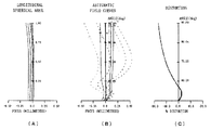
実施の形態1におけるレンズ系の基本構成は図2に示され、各数値データ(設定値)は表3、表4に、球面収差、歪曲収差、および非点収差を示す収差図は図3にそれぞれ示される。 The basic configuration of the lens system in the first embodiment is shown in FIG. 2, each numerical data (setting value) is shown in Tables 3 and 4, and the aberration diagram showing spherical aberration, distortion, and astigmatism is shown in FIG. Each is shown.
図2に示すように、第1レンズ110は物体側に凸面を向けたメニスカス形状、第2レンズ120は両凹形状、第3レンズ130は両凸形状、開口絞り140の像側に配置される第4レンズ150は両凸形状を有する。第2レンズ120と第4レンズ150はそれぞれ両面に非球面を有する。また、図に示すように第1レンズ110の厚さとなるR1面1とR2面2間の距離をD1、第1レンズ110のR2面2と第2レンズ120のR3面3までの距離をD2、第2レンズ120の厚さとなるR3面3とR4面4間の距離をD3、第2レンズ120のR4面4と第3レンズ130のR5面5間の距離をD4、第3レンズ130の厚さとなるR5面5とR6面6間の距離をD5、第3レンズ130のR6面6と絞り部の面7までの距離をD6、絞り部の面7と第4レンズ150のR7面8間の距離をD7、第4レンズ150の厚さとなるR7面8とR8面9間の距離をD8とする。
As shown in FIG. 2, the
表3は、実施例1における撮像レンズの各面番号に対応した絞り、各レンズの曲率半径R、間隔D、屈折率Nd、および分散値νdを示している。表3中で面番号に*がついている面は非球面形状となっていることを示す。表4は、所定面の非球面係数を示している。
<数値実施例1>
Table 3 shows the stop corresponding to each surface number of the imaging lens in Example 1, the radius of curvature R, the interval D, the refractive index Nd, and the dispersion value νd of each lens. In Table 3, the surface with * in the surface number indicates an aspherical shape. Table 4 shows the aspheric coefficient of the predetermined surface.
<Numerical Example 1>
図3は、実施例1において、図3(A)が球面収差(左から435.8nm,486.1nm,546.1nm,587.6nm,656.3nm)を、図3(B)が非点収差(実線:左から435.8nm,486.1nm,546.1nm,587.6nm,656.3nmのサジタル光線、点線:左から435.8nm,486.1nm,546.1nm,587.6nm,656.3nmのタンジェンシャル光線)を、図3(C)が歪曲収差(435.8nm,486.1nm,546.1nm,587.6nm,656.3nmが重なっている)をそれぞれ示している。図3(B)、(C)の縦軸は半画角ωを表し、図3(B)中、実線Mはメリディオナル像面の値、破線Sはサジタル像面の値をそれぞれ示している(図5、7、9、11においても同様である)。図3からわかるように、実施例1によれば、球面、歪曲、非点の諸収差が良好に補正され、結像性能に優れた撮像レンズが得られる。 3A is a spherical aberration (435.8 nm, 486.1 nm, 546.1 nm, 587.6 nm, 656.3 nm from the left), and FIG. 3B is an astigmatism (solid line: left) in Example 1. 35.8nm, 486.1nm, 546.1nm, 587.6nm, 656.3nm sagittal rays, dotted line: 435.8nm, 486.1nm, 546.1nm, 587.6nm, 656.3nm tangential rays from the left), Figure 3 (C) Distortion aberrations (435.8 nm, 486.1 nm, 546.1 nm, 587.6 nm, and 656.3 nm overlap) are shown. 3B and 3C, the vertical axis represents the half angle of view ω. In FIG. 3B, the solid line M represents the value of the meridional image plane, and the broken line S represents the value of the sagittal image plane ( The same applies to FIGS. 5, 7, 9, and 11). As can be seen from FIG. 3, according to the first embodiment, spherical, distorted, and astigmatism aberrations are satisfactorily corrected, and an imaging lens excellent in imaging performance can be obtained.
実施の形態2におけるレンズ系の基本構成は図4に示され、各数値データ(設定値)は表5、表6に、球面収差、歪曲収差、および非点収差を示す収差図は図5にそれぞれ示される。 The basic configuration of the lens system in the second embodiment is shown in FIG. 4, each numerical data (setting value) is shown in Tables 5 and 6, and aberration diagrams showing spherical aberration, distortion, and astigmatism are shown in FIG. Each is shown.
この実施例2における撮像レンズは様々な画角のMTFを重ね合わせ、中心付近の歪曲収差の発生を最低限にし、さらに小型化を目的に設計されている。 The imaging lens in Example 2 is designed for the purpose of miniaturization by minimizing the occurrence of distortion near the center by superimposing MTFs having various angles of view.
図4に示すように、第1レンズ110は物体側に凸面を向けたメニスカス形状、第2レンズ120は両凹形状、第3レンズ130は両凸形状、開口絞り140の像側に配置される第4レンズ150は両凸形状を有する。第2レンズ120と第4レンズ150はそれぞれ両面に非球面を有する。
As shown in FIG. 4, the
表3は、実施例1における撮像レンズの各面番号に対応した絞り、各レンズの曲率半径R、間隔D、屈折率Nd、および分散値νdを示している。表5中で面番号に*がついている面は非球面形状となっていることを示す。表6は、所定面の非球面係数を示している。
<数値実施例2>
Table 3 shows the stop corresponding to each surface number of the imaging lens in Example 1, the radius of curvature R, the interval D, the refractive index Nd, and the dispersion value νd of each lens. In Table 5, the surface numbered with * indicates that the surface is aspherical. Table 6 shows the aspheric coefficient of the predetermined surface.
<Numerical Example 2>
図5は、実施例2において、図5(A)が球面収差(左から435.8nm,486.1nm,546.1nm,587.6nm,656.3nm)を、図5(B)が非点収差(実線:左から435.8nm,486.1nm,546.1nm,587.6nm,656.3nmのサジタル光線、点線:左から435.8nm,486.1nm,546.1nm,587.6nm,656.3nmのタンジェンシャル光線)を、図5(C)が歪曲収差(435.8nm,486.1nm,546.1nm,587.6nm,656.3nmが重なっている)をそれぞれ示している。図5からわかるように、実施例2によれば、球面、歪曲、非点の諸収差が良好に補正され、結像性能に優れた撮像レンズが得られる。 5A is a spherical aberration (435.8 nm, 486.1 nm, 546.1 nm, 587.6 nm, 656.3 nm from the left) and FIG. 5B is an astigmatism (solid line: left) in Example 2. (5) to 435.8nm, 486.1nm, 546.1nm, 587.6nm, 656.3nm sagittal ray, dotted line: 435.8nm, 486.1nm, 546.1nm, 587.6nm, 656.3nm tangential rays from the left) Distortion aberrations (435.8 nm, 486.1 nm, 546.1 nm, 587.6 nm, and 656.3 nm overlap) are shown. As can be seen from FIG. 5, according to the second embodiment, the spherical lens, the distortion, and the astigmatism are satisfactorily corrected, and an imaging lens excellent in imaging performance can be obtained.
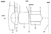
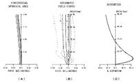
実施の形態3におけるレンズ系の基本構成は図6に示され、各数値データ(設定値)は表7、表8に、球面収差、歪曲収差、および非点収差を示す収差図は図7にそれぞれ示される。
The basic configuration of the lens system according to
この実施例3における撮像レンズは中心付近の歪曲収差の発生を抑え、小型化を目的に設計されている。 The imaging lens in Example 3 is designed for the purpose of miniaturization by suppressing the occurrence of distortion near the center.
図6に示すように、第1レンズ110は物体側に凸面を向けたメニスカス形状、第2レンズ120は物体側に凹面を向けたメニスカス形状、第3レンズ130は物体側に凸面を向けたメニスカス形状、開口絞り140の像側に配置される第4レンズ150は両凸形状を有する。第2レンズ120と第4レンズ150はそれぞれ両面に非球面を有する。
As shown in FIG. 6, the
表7は、実施例3における撮像レンズの各面番号に対応した絞り、各レンズの曲率半径R、間隔D、屈折率Nd、および分散値νdを示している。表7中で面番号に*がついている面は非球面形状となっていることを示す。表8は、所定面の非球面係数を示している。
<数値実施例3>
Table 7 shows the stop corresponding to each surface number of the imaging lens in Example 3, the radius of curvature R, the interval D, the refractive index Nd, and the dispersion value νd of each lens. In Table 7, the surface numbered with * indicates that the surface is aspherical. Table 8 shows the aspheric coefficient of the predetermined surface.
<Numerical Example 3>
図7は、実施例3おいて、図7(A)が球面収差(左から435.8nm,486.1nm,546.1nm,587.6nm,656.3nm)を、図7(B)が非点収差(実線:左から435.8nm,486.1nm,546.1nm,587.6nm,656.3nmのサジタル光線、点線:左から435.8nm,486.1nm,546.1nm,587.6nm,656.3nmのタンジェンシャル光線)を、図7(C)が歪曲収差(435.8nm,486.1nm,546.1nm,587.6nm,656.3nmが重なっている)をそれぞれ示している。図7からわかるように、実施例3によれば、球面、歪曲、非点の諸収差が良好に補正され、結像性能に優れた撮像レンズが得られる。 FIG. 7 shows the spherical aberration (435.8 nm, 486.1 nm, 546.1 nm, 587.6 nm, 656.3 nm from the left) and FIG. 7B shows the astigmatism (solid line: solid line) in Example 3. Sagittal rays of 435.8nm, 486.1nm, 546.1nm, 587.6nm, 656.3nm from the left, dotted line: 435.8nm, 486.1nm, 546.1nm, 587.6nm, 656.3nm tangential rays from the left), Fig. 7 (C) Shows distortion aberrations (435.8 nm, 486.1 nm, 546.1 nm, 587.6 nm, and 656.3 nm are overlapped), respectively. As can be seen from FIG. 7, according to the third embodiment, spherical, distorted, and astigmatism aberrations are satisfactorily corrected, and an imaging lens excellent in imaging performance can be obtained.
実施の形態4におけるレンズ系の基本構成は図8に示され、各数値データ(設定値)は表9、表10に、球面収差、歪曲収差、および非点収差を示す収差図は図9にそれぞれ示される。 The basic configuration of the lens system in the fourth embodiment is shown in FIG. 8, each numerical data (setting value) is shown in Tables 9 and 10, and the aberration diagram showing spherical aberration, distortion, and astigmatism is shown in FIG. Each is shown.
この実施例4における撮像レンズはMTFを向上させ、小型化を目的に設計されている。 The imaging lens in Example 4 is designed for the purpose of improving the MTF and reducing the size.
図8に示すように、第1レンズ110は物体側に凸面を向けたメニスカス形状、第2レンズ120は物体側に凹面を向けたメニスカス形状、第3レンズ130は物体側に凸面を向けたメニスカス形状、開口絞り140の像側に配置される第4レンズ150は両凸形状を有する。第2レンズ120と第4レンズ150はそれぞれ両面に非球面を有し、特に第2レンズの像側面4は中心付近で曲率の正負が逆転する変曲点を持つ。
As shown in FIG. 8, the
表9は、実施例1における撮像レンズの各面番号に対応した絞り、各レンズの曲率半径R、間隔D、屈折率Nd、および分散値νdを示している。表9中で面番号に*がついている面は非球面形状となっていることを示す。表10は、所定面の非球面係数を示している。
<数値実施例4>
Table 9 shows the diaphragm corresponding to each surface number of the imaging lens in Example 1, the radius of curvature R, the interval D, the refractive index Nd, and the dispersion value νd of each lens. In Table 9, the surface numbered with * indicates that the surface is aspherical. Table 10 shows the aspheric coefficient of the predetermined surface.
<Numerical Example 4>
図9は、実施例4おいて、図9(A)が球面収差(左から435.8nm,486.1nm,546.1nm,587.6nm,656.3nm)を、図9(B)が非点収差(実線:左から435.8nm,486.1nm,546.1nm,587.6nm,656.3nmのサジタル光線、点線:左から435.8nm,486.1nm,546.1nm,587.6nm,656.3nmのタンジェンシャル光線)を、図9(C)が歪曲収差(435.8nm,486.1nm,546.1nm,587.6nm,656.3nmが重なっている)をそれぞれ示している。図9からわかるように、実施例4によれば、球面、歪曲、非点の諸収差が良好に補正され、結像性能に優れた撮像レンズが得られる。 9A is a spherical aberration (435.8 nm, 486.1 nm, 546.1 nm, 587.6 nm, 656.3 nm from the left), and FIG. 9B is an astigmatism (solid line: solid line: Example 4). Sagittal rays of 435.8nm, 486.1nm, 546.1nm, 587.6nm, 656.3nm from the left, dotted line: tangential rays of 435.8nm, 486.1nm, 546.1nm, 587.6nm, 656.3nm from the left), Fig. 9 (C) Shows distortion aberrations (435.8 nm, 486.1 nm, 546.1 nm, 587.6 nm, and 656.3 nm are overlapped), respectively. As can be seen from FIG. 9, according to Example 4, various aberrations of spherical surface, distortion, and astigmatism are satisfactorily corrected, and an imaging lens excellent in imaging performance can be obtained.
実施の形態5におけるレンズ系の基本構成は図10に示され、各数値データ(設定値)は表11、表12に、球面収差、歪曲収差、および非点収差を示す収差図は図11にそれぞれ示される。
The basic configuration of the lens system according to
この実施例5における撮像レンズは小型化、特にレンズの最大有効径を小さくすることを目的に設計されている。 The imaging lens in Example 5 is designed for the purpose of downsizing, in particular, reducing the maximum effective diameter of the lens.
図10に示すように、第1レンズ110は物体側に凸面を向けたメニスカス形状、第2レンズ120は物体側に凹面を向けたメニスカス形状、第3レンズ130は両凸形状、開口絞り140の像側に配置される第4レンズ150は両凸形状を有する。第2レンズ120と第4レンズ150はそれぞれ両面に非球面を有し、特に第4レンズの像側面9は周辺で曲率の正負が逆転する変曲点を持つ。
As shown in FIG. 10, the
表11は、実施例5における撮像レンズの各面番号に対応した絞り、各レンズの曲率半径R、間隔D、屈折率Nd、および分散値νdを示している。表11中で面番号に*がついている面は非球面形状となっていることを示す。表12は、所定面の非球面係数を示している。
<数値実施例5>
Table 11 shows the stop corresponding to each surface number of the imaging lens in Example 5, the radius of curvature R, the interval D, the refractive index Nd, and the dispersion value νd of each lens. In Table 11, a surface numbered with * indicates that it has an aspherical shape. Table 12 shows the aspheric coefficient of the predetermined surface.
<Numerical example 5>
図11は、実施例5において、図11(A)が球面収差(左から435.8nm,486.1nm,546.1nm,587.6nm,656.3nm)を、図11(B)が非点収差(実線:左から435.8nm,486.1nm,546.1nm,587.6nm,656.3nmのサジタル光線、点線:左から435.8nm,486.1nm,546.1nm,587.6nm,656.3nmのタンジェンシャル光線)を、図11(C)が歪曲収差(435.8nm,486.1nm,546.1nm,587.6nm,656.3nmが重なっている)をそれぞれ示している。図11からわかるように、実施例5によれば、球面、歪曲、非点の諸収差が良好に補正され、結像性能に優れた撮像レンズが得られる。 11A is a spherical aberration (435.8 nm, 486.1 nm, 546.1 nm, 587.6 nm, 656.3 nm from the left), and FIG. 11B is an astigmatism (solid line: left) in Example 5. 115.8C, 486.1nm, 546.1nm, 587.6nm, 656.3nm sagittal rays, dotted line: 435.8nm, 486.1nm, 546.1nm, 587.6nm, 656.3nm tangential rays from the left), Fig. 11 (C) Distortion aberrations (435.8 nm, 486.1 nm, 546.1 nm, 587.6 nm, and 656.3 nm overlap) are shown. As can be seen from FIG. 11, according to the fifth embodiment, spherical, distorted, and astigmatism aberrations are corrected well, and an imaging lens excellent in imaging performance can be obtained.
100、100A、100B、100C、100D、100E … 撮像レンズ
110 … 第1レンズ
120 … 第2レンズ
130 … 第3レンズ
140 … 開口絞り部
150 … 第4レンズ
160 … 結像面
100, 100A, 100B, 100C, 100D, 100E ...
Claims (4)
d2/d1≦2 … (1)
d4/d3≦2 … (2)
但し、d1は第2レンズの最小厚、d2は第2レンズの最大厚、d3は第4レンズの最小厚、d4は第4レンズの最大厚である。 In order from the object side, a first lens which is a meniscus lens having a negative refractive power with a convex surface facing the object side, a second lens having a negative refractive power with a concave surface facing the object side, and a spherical surface, the object side A third lens having a positive refractive power with a convex surface facing the lens, an aperture stop, and a fourth lens having a positive refractive power with the convex surface facing the image side and at least one surface being an aspherical surface. An imaging lens satisfying the following conditional expressions (1) and (2).
d2 / d1 ≦ 2 (1)
d4 / d3 ≦ 2 (2)
However, d1 is the minimum thickness of the second lens, d2 is the maximum thickness of the second lens, d3 is the minimum thickness of the fourth lens, and d4 is the maximum thickness of the fourth lens.
a1/y≦2.1 …(3)
但し、a1は第1レンズのアパーチャー径、yは像高である。 The imaging lens according to claim 1, wherein the following conditional expression (3) is satisfied.
a1 / y ≦ 2.1 (3)
Here, a1 is the aperture diameter of the first lens, and y is the image height.
−5≦f1/f≦−2 … (4)
−5≦f2/f≦ −3 … (5)
3.0≦f3/f≦ 5.0 … (6)
0.5≦f4/f≦ 2.5 … (7)
但し、f1は第1レンズの焦点距離、f2は第2レンズの焦点距離、f3は第3レンズの焦点距離、f4は第4レンズの焦点距離である。
The imaging lens according to any one of claims 1 to 3, wherein the following conditional expressions (4) to (7) are satisfied.
−5 ≦ f1 / f ≦ −2 (4)
−5 ≦ f2 / f ≦ −3 (5)
3.0 ≦ f3 / f ≦ 5.0 (6)
0.5 ≦ f4 / f ≦ 2.5 (7)
Here, f1 is the focal length of the first lens, f2 is the focal length of the second lens, f3 is the focal length of the third lens, and f4 is the focal length of the fourth lens.
Priority Applications (1)
| Application Number | Priority Date | Filing Date | Title |
|---|---|---|---|
| JP2010025008A JP2011164237A (en) | 2010-02-08 | 2010-02-08 | Imaging lens |
Applications Claiming Priority (1)
| Application Number | Priority Date | Filing Date | Title |
|---|---|---|---|
| JP2010025008A JP2011164237A (en) | 2010-02-08 | 2010-02-08 | Imaging lens |
Publications (2)
| Publication Number | Publication Date |
|---|---|
| JP2011164237A true JP2011164237A (en) | 2011-08-25 |
| JP2011164237A5 JP2011164237A5 (en) | 2013-02-28 |
Family
ID=44595011
Family Applications (1)
| Application Number | Title | Priority Date | Filing Date |
|---|---|---|---|
| JP2010025008A Pending JP2011164237A (en) | 2010-02-08 | 2010-02-08 | Imaging lens |
Country Status (1)
| Country | Link |
|---|---|
| JP (1) | JP2011164237A (en) |
Cited By (10)
| Publication number | Priority date | Publication date | Assignee | Title |
|---|---|---|---|---|
| JP2011232418A (en) * | 2010-04-26 | 2011-11-17 | Fujifilm Corp | Imaging lens and imaging device |
| WO2014141347A1 (en) * | 2013-03-12 | 2014-09-18 | 富士フイルム株式会社 | Imaging lens and imaging device |
| JP2017134358A (en) * | 2016-01-29 | 2017-08-03 | 日立マクセル株式会社 | Imaging lens system and imaging apparatus |
| JP2017134359A (en) * | 2016-01-29 | 2017-08-03 | 日立マクセル株式会社 | Imaging lens system and imaging apparatus |
| WO2018163831A1 (en) * | 2017-03-10 | 2018-09-13 | パナソニックIpマネジメント株式会社 | Lens system, interchangeable lens device, and camera system |
| CN109358465A (en) * | 2018-12-11 | 2019-02-19 | 厦门力鼎光电股份有限公司 | A kind of optical imaging lens |
| JP2020030443A (en) * | 2019-11-28 | 2020-02-27 | マクセル株式会社 | Image capturing lens system and image capturing device |
| CN111352211A (en) * | 2018-12-23 | 2020-06-30 | 辽宁中蓝电子科技有限公司 | Small-head high-resolution lens |
| JP2020106682A (en) * | 2018-12-27 | 2020-07-09 | 株式会社タムロン | Optical system and image capturing device |
| JP2020170205A (en) * | 2020-07-22 | 2020-10-15 | マクセル株式会社 | Image capturing lens system and image capturing device |
Citations (4)
| Publication number | Priority date | Publication date | Assignee | Title |
|---|---|---|---|---|
| JP2007094032A (en) * | 2005-09-29 | 2007-04-12 | Fujinon Corp | Wide angle lens system and imaging apparatus |
| JP2007206516A (en) * | 2006-02-03 | 2007-08-16 | Enplas Corp | Imaging lens |
| JP2008242040A (en) * | 2007-03-27 | 2008-10-09 | Fujinon Corp | Wide-angle imaging lens and imaging apparatus |
| JP2008276185A (en) * | 2007-03-30 | 2008-11-13 | Ricoh Opt Ind Co Ltd | Wide-angle lens and image capturing apparatus |
-
2010
- 2010-02-08 JP JP2010025008A patent/JP2011164237A/en active Pending
Patent Citations (4)
| Publication number | Priority date | Publication date | Assignee | Title |
|---|---|---|---|---|
| JP2007094032A (en) * | 2005-09-29 | 2007-04-12 | Fujinon Corp | Wide angle lens system and imaging apparatus |
| JP2007206516A (en) * | 2006-02-03 | 2007-08-16 | Enplas Corp | Imaging lens |
| JP2008242040A (en) * | 2007-03-27 | 2008-10-09 | Fujinon Corp | Wide-angle imaging lens and imaging apparatus |
| JP2008276185A (en) * | 2007-03-30 | 2008-11-13 | Ricoh Opt Ind Co Ltd | Wide-angle lens and image capturing apparatus |
Cited By (19)
| Publication number | Priority date | Publication date | Assignee | Title |
|---|---|---|---|---|
| JP2011232418A (en) * | 2010-04-26 | 2011-11-17 | Fujifilm Corp | Imaging lens and imaging device |
| WO2014141347A1 (en) * | 2013-03-12 | 2014-09-18 | 富士フイルム株式会社 | Imaging lens and imaging device |
| CN105074530A (en) * | 2013-03-12 | 2015-11-18 | 富士胶片株式会社 | Imaging lens and imaging device |
| JP5838007B2 (en) * | 2013-03-12 | 2015-12-24 | 富士フイルム株式会社 | Imaging lens and imaging apparatus |
| JPWO2014141347A1 (en) * | 2013-03-12 | 2017-02-16 | 富士フイルム株式会社 | Imaging lens and imaging apparatus |
| CN105074530B (en) * | 2013-03-12 | 2018-01-12 | 富士胶片株式会社 | Imaging lens system and camera device |
| JP2017134358A (en) * | 2016-01-29 | 2017-08-03 | 日立マクセル株式会社 | Imaging lens system and imaging apparatus |
| JP2017134359A (en) * | 2016-01-29 | 2017-08-03 | 日立マクセル株式会社 | Imaging lens system and imaging apparatus |
| WO2018163831A1 (en) * | 2017-03-10 | 2018-09-13 | パナソニックIpマネジメント株式会社 | Lens system, interchangeable lens device, and camera system |
| JPWO2018163831A1 (en) * | 2017-03-10 | 2020-01-16 | パナソニックIpマネジメント株式会社 | Lens system, interchangeable lens device and camera system |
| US11320630B2 (en) | 2017-03-10 | 2022-05-03 | Panasonic Intellectual Property Management Co., Ltd. | Lens system, interchangeable lens device, and camera system |
| JP7117638B2 (en) | 2017-03-10 | 2022-08-15 | パナソニックIpマネジメント株式会社 | Lens system, interchangeable lens device and camera system |
| CN109358465A (en) * | 2018-12-11 | 2019-02-19 | 厦门力鼎光电股份有限公司 | A kind of optical imaging lens |
| CN111352211A (en) * | 2018-12-23 | 2020-06-30 | 辽宁中蓝电子科技有限公司 | Small-head high-resolution lens |
| JP2020106682A (en) * | 2018-12-27 | 2020-07-09 | 株式会社タムロン | Optical system and image capturing device |
| JP7285643B2 (en) | 2018-12-27 | 2023-06-02 | 株式会社タムロン | Optical system and imaging device |
| JP2020030443A (en) * | 2019-11-28 | 2020-02-27 | マクセル株式会社 | Image capturing lens system and image capturing device |
| JP2020170205A (en) * | 2020-07-22 | 2020-10-15 | マクセル株式会社 | Image capturing lens system and image capturing device |
| JP6997265B2 (en) | 2020-07-22 | 2022-02-04 | マクセル株式会社 | Imaging lens system and imaging device |
Similar Documents
| Publication | Publication Date | Title |
|---|---|---|
| JP5252842B2 (en) | Imaging lens | |
| JP4887507B1 (en) | Imaging lens | |
| JP6005941B2 (en) | Imaging lens | |
| JP5513641B1 (en) | Imaging lens | |
| JP2011164237A (en) | Imaging lens | |
| CN102540425B (en) | Imaging lens system | |
| JP4792542B1 (en) | Imaging lens | |
| JP2008268268A (en) | Imaging lens | |
| CN111913274A (en) | Imaging optical system and imaging device | |
| JP2005284153A (en) | Imaging lens | |
| JP2008281859A (en) | Wide angle lens | |
| JP5952135B2 (en) | Ultra-small imaging lens | |
| JP2017102182A (en) | Imaging lens and imaging apparatus | |
| JP2017102183A (en) | Imaging lens and imaging apparatus | |
| JP2006201674A (en) | Wide angle imaging lens | |
| JP2009265338A (en) | Wide-angle imaging lens | |
| JP2009169165A (en) | Imaging lens | |
| JP4222623B1 (en) | Imaging lens | |
| JP2019184723A (en) | Image capturing lens | |
| JP5725967B2 (en) | Imaging lens | |
| JP5693352B2 (en) | Imaging lens | |
| JP2008292651A (en) | Imaging lens | |
| JP2012177736A (en) | Imaging lens | |
| JP5825845B2 (en) | Imaging lens | |
| JP2011027875A (en) | Taking lens |
Legal Events
| Date | Code | Title | Description |
|---|---|---|---|
| A521 | Request for written amendment filed |
Free format text: JAPANESE INTERMEDIATE CODE: A523 Effective date: 20130111 |
|
| A621 | Written request for application examination |
Free format text: JAPANESE INTERMEDIATE CODE: A621 Effective date: 20130115 |
|
| A977 | Report on retrieval |
Free format text: JAPANESE INTERMEDIATE CODE: A971007 Effective date: 20131016 |
|
| A131 | Notification of reasons for refusal |
Free format text: JAPANESE INTERMEDIATE CODE: A131 Effective date: 20131022 |
|
| A521 | Request for written amendment filed |
Free format text: JAPANESE INTERMEDIATE CODE: A523 Effective date: 20131224 |
|
| A02 | Decision of refusal |
Free format text: JAPANESE INTERMEDIATE CODE: A02 Effective date: 20140212 |