JP2011158868A - Imaging lens and imaging device - Google Patents
Imaging lens and imaging device Download PDFInfo
- Publication number
- JP2011158868A JP2011158868A JP2010022927A JP2010022927A JP2011158868A JP 2011158868 A JP2011158868 A JP 2011158868A JP 2010022927 A JP2010022927 A JP 2010022927A JP 2010022927 A JP2010022927 A JP 2010022927A JP 2011158868 A JP2011158868 A JP 2011158868A
- Authority
- JP
- Japan
- Prior art keywords
- lens
- optical axis
- imaging
- image
- conditional expression
- Prior art date
- Legal status (The legal status is an assumption and is not a legal conclusion. Google has not performed a legal analysis and makes no representation as to the accuracy of the status listed.)
- Pending
Links
- 238000003384 imaging method Methods 0.000 title claims abstract description 90
- 230000003287 optical effect Effects 0.000 claims abstract description 81
- 230000014509 gene expression Effects 0.000 claims description 58
- 239000000463 material Substances 0.000 claims description 35
- 230000004075 alteration Effects 0.000 description 39
- 239000003981 vehicle Substances 0.000 description 13
- 239000004033 plastic Substances 0.000 description 9
- 238000010586 diagram Methods 0.000 description 8
- 230000000694 effects Effects 0.000 description 8
- 238000012937 correction Methods 0.000 description 7
- 230000001965 increasing effect Effects 0.000 description 7
- XLYOFNOQVPJJNP-UHFFFAOYSA-N water Substances O XLYOFNOQVPJJNP-UHFFFAOYSA-N 0.000 description 7
- 206010010071 Coma Diseases 0.000 description 6
- 230000002093 peripheral effect Effects 0.000 description 5
- 238000004519 manufacturing process Methods 0.000 description 4
- 238000010521 absorption reaction Methods 0.000 description 3
- 201000009310 astigmatism Diseases 0.000 description 3
- 239000011521 glass Substances 0.000 description 3
- 238000000034 method Methods 0.000 description 3
- 239000000126 substance Substances 0.000 description 3
- 230000008901 benefit Effects 0.000 description 2
- 238000006243 chemical reaction Methods 0.000 description 2
- 239000006059 cover glass Substances 0.000 description 2
- 230000006866 deterioration Effects 0.000 description 2
- 239000000428 dust Substances 0.000 description 2
- 230000005499 meniscus Effects 0.000 description 2
- 239000005304 optical glass Substances 0.000 description 2
- 239000004417 polycarbonate Substances 0.000 description 2
- 229920000515 polycarbonate Polymers 0.000 description 2
- 229920000098 polyolefin Polymers 0.000 description 2
- 230000001681 protective effect Effects 0.000 description 2
- 230000009467 reduction Effects 0.000 description 2
- 239000002253 acid Substances 0.000 description 1
- 230000009471 action Effects 0.000 description 1
- 230000002411 adverse Effects 0.000 description 1
- 238000013459 approach Methods 0.000 description 1
- 238000001444 catalytic combustion detection Methods 0.000 description 1
- 239000000919 ceramic Substances 0.000 description 1
- 230000008859 change Effects 0.000 description 1
- 238000004140 cleaning Methods 0.000 description 1
- 239000011248 coating agent Substances 0.000 description 1
- 238000000576 coating method Methods 0.000 description 1
- 230000000295 complement effect Effects 0.000 description 1
- 230000002708 enhancing effect Effects 0.000 description 1
- 230000004907 flux Effects 0.000 description 1
- 229910044991 metal oxide Inorganic materials 0.000 description 1
- 150000004706 metal oxides Chemical class 0.000 description 1
- 238000012986 modification Methods 0.000 description 1
- 230000004048 modification Effects 0.000 description 1
- 238000012544 monitoring process Methods 0.000 description 1
- 239000002114 nanocomposite Substances 0.000 description 1
- 235000014593 oils and fats Nutrition 0.000 description 1
- 239000003973 paint Substances 0.000 description 1
- 239000002245 particle Substances 0.000 description 1
- 239000000843 powder Substances 0.000 description 1
- 230000008569 process Effects 0.000 description 1
- 230000002940 repellent Effects 0.000 description 1
- 239000005871 repellent Substances 0.000 description 1
- 239000011347 resin Substances 0.000 description 1
- 229920005989 resin Polymers 0.000 description 1
- 239000004576 sand Substances 0.000 description 1
- 239000004065 semiconductor Substances 0.000 description 1
- 238000004904 shortening Methods 0.000 description 1
- 239000002904 solvent Substances 0.000 description 1
- 230000009466 transformation Effects 0.000 description 1
Images


Classifications
-
- G—PHYSICS
- G02—OPTICS
- G02B—OPTICAL ELEMENTS, SYSTEMS OR APPARATUS
- G02B13/00—Optical objectives specially designed for the purposes specified below
- G02B13/001—Miniaturised objectives for electronic devices, e.g. portable telephones, webcams, PDAs, small digital cameras
- G02B13/0015—Miniaturised objectives for electronic devices, e.g. portable telephones, webcams, PDAs, small digital cameras characterised by the lens design
- G02B13/002—Miniaturised objectives for electronic devices, e.g. portable telephones, webcams, PDAs, small digital cameras characterised by the lens design having at least one aspherical surface
- G02B13/004—Miniaturised objectives for electronic devices, e.g. portable telephones, webcams, PDAs, small digital cameras characterised by the lens design having at least one aspherical surface having four lenses
Abstract
Description
本発明は、撮像レンズおよび撮像装置に関し、より詳しくは、CCD(Charge Coupled Device)やCMOS(Complementary Metal Oxide Semiconductor)等の撮像素子を用いた車載用カメラ、監視カメラ等に使用されるのに好適な広角の撮像レンズ、および該撮像レンズを備えた撮像装置に関するものである。 The present invention relates to an imaging lens and an imaging apparatus, and more particularly, suitable for use in an in-vehicle camera, a monitoring camera, or the like using an imaging device such as a CCD (Charge Coupled Device) or a CMOS (Complementary Metal Oxide Semiconductor). The present invention relates to a wide-angle imaging lens and an imaging apparatus including the imaging lens.
CCDやCMOS等の撮像素子は近年非常に小型化および高画素化が進んでいる。そのため、撮像機器本体並びにそれに搭載される撮像レンズにも小型化、軽量化が求められている。一方、車載用カメラ、監視カメラ等に使用される撮像レンズには、高い耐候性を持ち、広範囲にわたって良好な視界を確保できるように広画角で高い光学性能を有することが求められている。 In recent years, image sensors such as CCDs and CMOSs have been greatly reduced in size and pixels. For this reason, the imaging device body and the imaging lens mounted thereon are also required to be small and light. On the other hand, an imaging lens used for a vehicle-mounted camera, a surveillance camera, or the like is required to have high weather resistance and high optical performance with a wide angle of view so as to ensure a good field of view over a wide range.
さらに、上記分野の撮像レンズにおいては、低コスト化が望まれていることから、レンズ枚数が少ない光学系が求められている。従来、上記分野における4枚構成の撮像レンズとしては、例えば下記特許文献1〜5に記載のものが知られている。 Further, in the imaging lens in the above field, since cost reduction is desired, an optical system with a small number of lenses is required. Conventionally, as a four-lens imaging lens in the above field, for example, those described in Patent Documents 1 to 5 below are known.
ところで近年では、車載用カメラや監視カメラ等の分野において、例えば全画角で180°を超えるものが望まれるなど、広角化に対する要望が強まってきている。また、近年の撮像素子の小型化および高画素化に伴い、高い解像性を有し、結像領域の広い範囲まで良好な像が得られるような高い光学性能を有する撮像レンズが求められるようになってきている。しかしながら、従来のレンズ系では、安価で小型に構成しながら、近年の要望を満たす程度の広角化と高い光学性能を同時に実現することは困難であった。 By the way, in recent years, in the field of in-vehicle cameras, surveillance cameras, and the like, there is an increasing demand for wide angle, for example, a camera having a total angle of view exceeding 180 ° is desired. In addition, with recent downsizing of imaging devices and increase in pixels, an imaging lens having high resolution and high optical performance that can obtain a good image up to a wide range of the imaging region is required. It is becoming. However, with the conventional lens system, it has been difficult to simultaneously realize a wide angle and high optical performance that satisfy recent demands while being inexpensive and compact.
特許文献1には、実施例3の広角レンズとして、物体側から順に配置された第1レンズ〜第4レンズの4枚のレンズで構成され、第3レンズと第4レンズの間に絞りが配置されたレンズ系が記載されている。特許文献1にはこのレンズ系のFナンバー、画角に関する記載はないが、第1レンズの屈折率が1.52程度であり、第1レンズ、第2レンズの負のパワーが比較的小さいため、このレンズ系が全画角が180°を超える仕様に対応できるものとは考えにくい。 In Patent Document 1, the wide-angle lens of Example 3 is composed of four lenses, a first lens to a fourth lens, which are arranged in order from the object side, and a diaphragm is arranged between the third lens and the fourth lens. The described lens system is described. Although there is no description regarding the F number and the angle of view of this lens system in Patent Document 1, the refractive power of the first lens is about 1.52, and the negative power of the first lens and the second lens is relatively small. This lens system is unlikely to be compatible with specifications with a total field angle exceeding 180 °.
特許文献2、3に記載されたレンズは、それぞれの全画角が約140°〜165°、約152°〜164°であり、近年要望されている全画角が180°を超えるような広角化に対応できるものとは言えない。特許文献4に記載されたレンズは、Fナンバーが2.5〜2.8であり、全画角が180°以上であるが、全系の焦点距離f、半画角φを用いて、理想像高を2×f×tan(φ/2)とする射影方式を採用した場合、ディストーションが半画角80°を超えてから急激にマイナス側に大きくなるため、最周辺部の画像が小さくなるという短所がある。特許文献5には、全画角が190°に近い実施例が記載されており、歪曲収差、倍率の色収差ともに良好に補正されているが、非点収差が残存しており、高画素化が進んだ撮像素子と組み合わせて使用する際に、さらに広い深度を要求される場合がある。
The lenses described in
本発明は、上記事情に鑑み、小型かつ低コストでありながら、広角化と高い光学性能を実現可能な撮像レンズ、および該撮像レンズを備えた撮像装置を提供することを目的とするものである。 In view of the above circumstances, an object of the present invention is to provide an imaging lens capable of realizing a wide angle and high optical performance while being small and low-cost, and an imaging apparatus including the imaging lens. .
本発明の撮像レンズは、物体側から順に、負のパワーを持ち、物体側の面が凸形状であり、像側の面が凹形状である第1レンズと、物体側の面および像側の面が非球面であり、光軸近傍で負のパワーを持ち、物体側の面が光軸近傍で凸形状であり、像側の面が光軸近傍で凹形状である第2レンズと、物体側の面および像側の面が非球面であり、光軸近傍で正のパワーを持ち、物体側の面が光軸近傍で凸形状であり、像側の面が光軸近傍で凹形状である第3レンズと、絞りと、物体側の面および像側の面が非球面であり、光軸近傍で正のパワーを持ち、物体側の面が光軸近傍で凹形状であり、像側の面が光軸近傍で凸形状である第4レンズとが配されてなることを特徴とするものである。 The imaging lens of the present invention has, in order from the object side, a first lens having negative power, a convex surface on the object side, and a concave shape on the image side, and an object side surface and an image side surface. A second lens whose surface is aspheric, has negative power near the optical axis, the object side surface is convex near the optical axis, and the image side surface is concave near the optical axis; The surface on the side and the surface on the image side are aspherical, have positive power near the optical axis, the surface on the object side is convex near the optical axis, and the surface on the image side is concave near the optical axis. A third lens, a stop, an object-side surface and an image-side surface are aspheric surfaces, have positive power near the optical axis, and the object-side surface has a concave shape near the optical axis. And a fourth lens having a convex shape near the optical axis.
なお、本発明の撮像レンズの第1レンズに関する上記「負のパワーを持ち、物体側の面が凸形状であり、像側の面が凹形状」は、第1レンズが非球面レンズの場合は、近軸領域におけるものとする。また、上記「光軸近傍」は近軸領域と同義の意味とする。 The above-mentioned “having negative power, the object-side surface is convex and the image-side surface is concave” relating to the first lens of the imaging lens of the present invention means that the first lens is an aspheric lens. , In the paraxial region. The “near the optical axis” has the same meaning as the paraxial region.
本発明の撮像レンズにおいては、下記条件式(1)〜(6)を満足することが好ましい。なお、好ましい態様としては、下記条件式(1)〜(6)のいずれか1つを満足するものでもよく、あるいは任意の2つ以上の組合せを満足するものでもよい。
−11.0<f1/f<−8.0 … (1)
0.16<d2/L<0.30 … (2)
0.02<d4/L<0.05 … (3)
−1.2<f2/f3<−0.5 … (4)
2.0<L/f34<6.0 … (5)
1.0<r5/r4<2.0 … (6)
ただし、
f:全系の焦点距離
f1:第1レンズの焦点距離
f2:第2レンズの焦点距離
f3:第3レンズの焦点距離
f34:第3レンズと第4レンズの合成焦点距離
d2:第1レンズと第2レンズの光軸上の間隔
d4:第2レンズと第3レンズの光軸上の間隔
r4:第2レンズの像側の面の近軸曲率半径
r5:第3レンズの物体側の面の近軸曲率半径
L:第1レンズの物体側の面頂点から像面までの光軸上の距離
In the imaging lens of the present invention, it is preferable that the following conditional expressions (1) to (6) are satisfied. In addition, as a preferable aspect, any one of the following conditional expressions (1) to (6) may be satisfied, or any combination of two or more may be satisfied.
−11.0 <f1 / f <−8.0 (1)
0.16 <d2 / L <0.30 (2)
0.02 <d4 / L <0.05 (3)
−1.2 <f2 / f3 <−0.5 (4)
2.0 <L / f34 <6.0 (5)
1.0 <r5 / r4 <2.0 (6)
However,
f: focal length of the entire system f1: focal length of the first lens f2: focal length of the second lens f3: focal length of the third lens f34: combined focal length of the third lens and the fourth lens d2: with the first lens The distance d4 on the optical axis of the second lens: the distance r4 on the optical axis of the second lens and the third lens r4: the paraxial radius of curvature r5 of the image side surface of the second lens: the surface of the object side surface of the third lens Paraxial radius of curvature L: Distance on the optical axis from the surface apex on the object side of the first lens to the image plane
なお、上記Lのうち、バックフォーカス分は空気換算長を用いるものとする。また、上記r4、r5の符号は、物体側に凸の場合を正、像側に凸の場合を負とすることにする。 It should be noted that the air conversion length is used for the back focus of L. The signs of r4 and r5 are positive when convex on the object side and negative when convex on the image side.
本発明の撮像レンズにおいては、第1レンズの材質のd線におけるアッベ数は40以上であることが好ましい。第2レンズの材質のd線におけるアッベ数は50以上であることが好ましい。第3レンズの材質のd線におけるアッベ数は40以下であることが好ましい。第4レンズの材質のd線におけるアッベ数は50以上であることが好ましい。 In the imaging lens of the present invention, it is preferable that the Abbe number of the first lens material at the d-line is 40 or more. The Abbe number in the d-line of the material of the second lens is preferably 50 or more. The Abbe number of the third lens material at the d-line is preferably 40 or less. The Abbe number in the d-line of the material of the fourth lens is preferably 50 or more.
また、本発明の撮像レンズにおいては、全画角が200°より大きいように構成することが好ましい。 In addition, the imaging lens of the present invention is preferably configured so that the total angle of view is greater than 200 °.
本発明の撮像装置は、上記記載の本発明の撮像レンズを備えたことを特徴とするものである。 An image pickup apparatus of the present invention includes the above-described image pickup lens of the present invention.
本発明の撮像レンズによれば、4枚のレンズ系において、各レンズのパワーおよび形状を好適に設定し、絞りを好適な位置に配置しているため、安価で小型に構成しながら、広角化と高い光学性能を同時に実現することができる。 According to the imaging lens of the present invention, in the four-lens system, the power and shape of each lens are suitably set, and the diaphragm is arranged at a suitable position. High optical performance can be realized at the same time.
本発明の撮像装置によれば、本発明の撮像レンズを備えているため、安価で小型に構成でき、広い画角での撮像が可能であり、高画質の映像を得ることができる。 According to the image pickup apparatus of the present invention, since the image pickup lens of the present invention is provided, the image pickup apparatus of the present invention can be configured inexpensively and compactly, can be picked up with a wide angle of view, and high-quality images can be obtained.
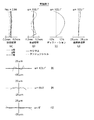
以下、本発明の実施形態について図面を参照して詳細に説明する。図1〜図3は、本発明の実施形態にかかる撮像レンズの構成例を示す断面図であり、それぞれ後述の実施例1〜3の撮像レンズに対応している。図1〜図3に示す例の基本的な構成は同様であり、図示方法も同様であるため、ここでは主に図1を参照しながら、本発明の実施形態にかかる撮像レンズについて説明する。 Hereinafter, embodiments of the present invention will be described in detail with reference to the drawings. 1 to 3 are sectional views showing a configuration example of an imaging lens according to an embodiment of the present invention, and correspond to imaging lenses of Examples 1 to 3 described later, respectively. Since the basic configuration of the example shown in FIGS. 1 to 3 is the same and the method of illustration is also the same, here, an imaging lens according to an embodiment of the present invention will be described mainly with reference to FIG.
本実施形態の撮像レンズは、光軸Zに沿って、物体側から順に、第1レンズL1と、第2レンズL2と、第3レンズL3と、第4レンズL4とが配された4枚構成のレンズ系である。第3レンズL3と第4レンズL4の間には、開口絞りStが配置されている。開口絞りStを第3レンズL3と第4レンズL4の間に配置することにより、径方向の小型化を図ることができる。 The imaging lens of the present embodiment has a four-lens configuration in which a first lens L1, a second lens L2, a third lens L3, and a fourth lens L4 are arranged in order from the object side along the optical axis Z. Lens system. An aperture stop St is disposed between the third lens L3 and the fourth lens L4. By arranging the aperture stop St between the third lens L3 and the fourth lens L4, it is possible to reduce the size in the radial direction.
なお、図1では、左側が物体側、右側が像側としており、図示されている開口絞りStは必ずしも大きさや形状を表すものではなく、光軸上の位置を示すものである。図1中の符号ri(i=1、2、3、…)は、各レンズ面の曲率半径を示し、符号di(i=1、2、3、…)は面間隔を示す。また、図1には、無限遠の距離にある物点からの軸上光束2、最大画角での軸外光束3も合わせて示す。
In FIG. 1, the left side is the object side and the right side is the image side, and the illustrated aperture stop St does not necessarily indicate the size or shape, but indicates the position on the optical axis. In FIG. 1, symbol ri (i = 1, 2, 3,...) Indicates the radius of curvature of each lens surface, and symbol di (i = 1, 2, 3,...) Indicates the surface interval. FIG. 1 also shows an
図1では、撮像レンズが撮像装置に適用される場合を考慮して、撮像レンズ1の像面Simに配置された撮像素子5も図示している。また、撮像レンズ1を撮像装置に適用する際には、レンズを装着するカメラ側の構成に応じて、カバーガラスや、ローパスフィルタまたは赤外線カットフィルタ等を設けることが好ましく、図1では、これらを想定した平行平板状の光学部材PPを第4レンズL4と撮像素子5(像面Sim)の間に配置した例を示している。
In FIG. 1, the
第1レンズL1は、負のパワーを持ち、物体側の面が凸形状であり、像側の面が凹形状であるように構成される。このように第1レンズL1を物体側に凸面を向けた負メニスカスレンズとすることにより、広角化およびディストーションの補正に有利となる。最も物体側に配置される第1レンズL1は、風雨や洗浄用の溶剤に晒されることが想定されるが、第1レンズL1を物体側に凸面を向けたメニスカス形状とすれば、これらの状況において懸念されるゴミ、埃、水滴等が残留しにくいという利点もある。 The first lens L1 has a negative power, and is configured such that the object-side surface has a convex shape and the image-side surface has a concave shape. Thus, by using the first lens L1 as a negative meniscus lens having a convex surface facing the object side, it is advantageous for widening the angle and correcting distortion. The first lens L1 arranged closest to the object side is assumed to be exposed to wind and rain or a cleaning solvent. However, if the first lens L1 has a meniscus shape with a convex surface facing the object side, these situations are assumed. There is also an advantage that dust, dust, water droplets, etc., which are of concern in Japan, are difficult to remain.
なお、図1に示す例では第1レンズL1は球面レンズで構成しているが、非球面レンズで構成することも可能である。ただし、後述のように、最も物体側に配置される第1レンズの材質は、樹脂よりもガラスの方が好ましいことから、第1レンズL1を球面レンズとすれば、非球面レンズとした場合よりも低コストに製作することができる。 In the example shown in FIG. 1, the first lens L1 is a spherical lens, but may be an aspheric lens. However, as will be described later, the material of the first lens arranged closest to the object side is preferably glass rather than resin. Therefore, if the first lens L1 is a spherical lens, it is more than an aspherical lens. Can be manufactured at low cost.
第2レンズL2、第3レンズL3、第4レンズL4は全て、物体側の面および像側の面が非球面形状である。第2レンズL2は、光軸近傍で負のパワーを持ち、物体側の面が光軸近傍で凸形状であり、像側の面が光軸近傍で凹形状であるように構成される。第3レンズL3は、光軸近傍で正のパワーを持ち、物体側の面が光軸近傍で凸形状であり、像側の面が光軸近傍で凹形状であるように構成される。第4レンズL4は、光軸近傍で正のパワーを持ち、物体側の面が光軸近傍で凹形状であり、像側の面が光軸近傍で凸形状であるように構成される。第2レンズL2、第3レンズL3、第4レンズL4を両面非球面のレンズとすることで、光学系の光軸方向の全長を短くしながらも高い解像性を得ることが可能になる。 The second lens L2, the third lens L3, and the fourth lens L4 all have an aspherical shape on the object side surface and the image side surface. The second lens L2 has a negative power in the vicinity of the optical axis, and is configured such that the object-side surface has a convex shape in the vicinity of the optical axis, and the image-side surface has a concave shape in the vicinity of the optical axis. The third lens L3 has a positive power in the vicinity of the optical axis, and is configured such that the object side surface has a convex shape in the vicinity of the optical axis, and the image side surface has a concave shape in the vicinity of the optical axis. The fourth lens L4 has a positive power near the optical axis, and is configured such that the object side surface has a concave shape near the optical axis and the image side surface has a convex shape near the optical axis. By using the second lens L2, the third lens L3, and the fourth lens L4 as double-sided aspheric lenses, it is possible to obtain high resolution while shortening the total length of the optical system in the optical axis direction.
本撮像レンズは、4群4枚のレンズ構成において、上記のように第1レンズL1〜第4レンズの各レンズのパワーおよび形状を好適に設定し、開口絞りStを第3レンズL3と第4レンズL4の間に配置することにより、少ないレンズ枚数および短い全長で小型かつ低コストに構成しながら、十分な広角化を達成し、さらに像面湾曲を始め歪曲収差、倍率の色収差、コマ収差を含む諸収差を良好に補正することができる。本撮像レンズによれば、結像領域の広い範囲にわたって高解像を実現することができるため、近年の高画素化が進んだ撮像素子にも対応することが可能になる。 In this imaging lens, in the four-group four-lens configuration, the power and shape of each of the first lens L1 to the fourth lens are suitably set as described above, and the aperture stop St is set to the third lens L3 and the fourth lens. By arranging it between the lenses L4, a small and low-cost configuration with a small number of lenses and a short overall length achieves a sufficiently wide angle, and further, distortion, chromatic aberration of magnification, and coma, including field curvature, are reduced. Various aberrations can be corrected satisfactorily. According to the present imaging lens, since high resolution can be realized over a wide range of the imaging region, it is possible to cope with an imaging element that has recently increased in number of pixels.
本発明の実施形態にかかる撮像レンズは、さらに以下に述べる構成を有することが好ましい。なお、好ましい態様としては、以下のいずれか1つの構成を有するものでもよく、あるいは任意の2つ以上を組合せた構成を有するものでもよい。 The imaging lens according to the embodiment of the present invention preferably further has a configuration described below. In addition, as a preferable aspect, it may have any one of the following configurations, or may have a configuration in which any two or more are combined.
第1レンズL1の焦点距離をf1とし、全系の焦点距離をfとしたとき、下記条件式(1)を満足することが好ましい。
−11.0<f1/f<−8.0 … (1)
When the focal length of the first lens L1 is f1, and the focal length of the entire system is f, it is preferable that the following conditional expression (1) is satisfied.
−11.0 <f1 / f <−8.0 (1)
条件式(1)の上限を上回ると、第1レンズL1の負のパワーが強くなるため、第1レンズL1の像側の面の曲率半径の絶対値が小さくなって半球形状に近くなり、第1レンズL1の製作が難しくなるため、コストアップになる。条件式(1)の下限を下回ると、第1レンズL1の負のパワーが弱くなり、それを補うために第2レンズL2の負のパワーを強くしなくてはならず、第2レンズL2の曲率半径の絶対値が小さくなるため、第2レンズの製作が難しくなり、コストアップになる。 If the upper limit of conditional expression (1) is exceeded, the negative power of the first lens L1 becomes stronger, so the absolute value of the radius of curvature of the image-side surface of the first lens L1 becomes smaller and becomes closer to a hemispherical shape. Since it becomes difficult to manufacture one lens L1, the cost increases. If the lower limit of conditional expression (1) is surpassed, the negative power of the first lens L1 becomes weak, and in order to compensate for this, the negative power of the second lens L2 must be increased. Since the absolute value of the radius of curvature is small, it is difficult to manufacture the second lens, which increases costs.
さらに、下記条件式(1−1)を満たすことがより好ましい。条件式(1−1)を満たすことで、条件式(1)を満たすことにより得られる効果をさらに高めることができる。
−10.5<f1/f<−8.5 … (1−1)
Furthermore, it is more preferable to satisfy the following conditional expression (1-1). By satisfying conditional expression (1-1), the effect obtained by satisfying conditional expression (1) can be further enhanced.
−10.5 <f1 / f <−8.5 (1-1)
またさらに、下記条件式(1−2)を満たすことがよりいっそう好ましい。条件式(1−2)を満たすことで、条件式(1−1)を満たす場合よりもさらに製作コストを抑制することが可能となる。
−10.0<f1/f<−8.5 … (1−2)
It is even more preferable that the following conditional expression (1-2) is satisfied. By satisfying conditional expression (1-2), it is possible to further reduce the manufacturing cost as compared with the case where conditional expression (1-1) is satisfied.
−10.0 <f1 / f <−8.5 (1-2)
第1レンズL1と第2レンズL2の光軸上の間隔をd2とし、第1レンズL1の物体側の面の面頂点から像面までの距離をLとしたとき、下記条件式(2)を満足することが好ましい。なお、Lはバックフォーカス分は空気換算長を用いるものとする。
0.16<d2/L<0.30 … (2)
When the distance on the optical axis between the first lens L1 and the second lens L2 is d2, and the distance from the surface vertex of the object side surface of the first lens L1 to the image plane is L, the following conditional expression (2) is satisfied. It is preferable to satisfy. Note that L is the air equivalent length for the back focus.
0.16 <d2 / L <0.30 (2)
条件式(2)の上限を上回ると、第1レンズL1の像側の面の有効半径が大きくなり曲率半径に近づくためレンズの加工が困難になるのでコストアップになるとともに、レンズ系の光軸方向の全長が長くなる。条件式(2)の下限を下回った状態で第1レンズL1に適正なパワーを確保しようとすると、第1レンズL1の像側の面と第2レンズL2の物体側の面が干渉してしまい、必要な有効半径を確保できなくなり、本発明の目的とする光学系を実現することが困難になる。 If the upper limit of conditional expression (2) is exceeded, the effective radius of the image-side surface of the first lens L1 becomes large and approaches the radius of curvature, which makes it difficult to process the lens, increasing costs and increasing the optical axis of the lens system. The total length in the direction becomes longer. If an attempt is made to secure appropriate power to the first lens L1 in a state where the lower limit of the conditional expression (2) is not reached, the image side surface of the first lens L1 and the object side surface of the second lens L2 interfere with each other. Therefore, it becomes impossible to secure a necessary effective radius, and it becomes difficult to realize an optical system as an object of the present invention.
さらに、下記条件式(2−1)を満たすことがより好ましい。条件式(2−1)を満たすことで、条件式(2)を満たすことにより得られる効果をさらに高めることができる。
0.17<d2/L<0.25 … (2−1)
Furthermore, it is more preferable to satisfy the following conditional expression (2-1). By satisfying conditional expression (2-1), the effect obtained by satisfying conditional expression (2) can be further enhanced.
0.17 <d2 / L <0.25 (2-1)
第2レンズL2と第3レンズL3の光軸上の間隔をd4とし、第1レンズL1の物体側の面の面頂点から像面までの距離をLとしたとき、下記条件式(3)を満足することが好ましい。なお、Lはバックフォーカス分は空気換算長を用いるものとする。
0.02<d4/L<0.05 … (3)
When the distance on the optical axis between the second lens L2 and the third lens L3 is d4 and the distance from the surface vertex of the object side surface of the first lens L1 to the image plane is L, the following conditional expression (3) It is preferable to satisfy. Note that L is the air equivalent length for the back focus.
0.02 <d4 / L <0.05 (3)
条件式(3)の上限を上回ると、倍率色収差を良好に保ちながらディストーションを良好に補正することが難しくなり、また、レンズ系の全長が長くなる。第2レンズL2の像側の面と第3レンズL3の物体側の面は有効径内で接触しなければよいが、条件式(3)の下限を下回ると、これらが接触する危険性が増大してしまう。 When the upper limit of conditional expression (3) is exceeded, it becomes difficult to correct distortion well while maintaining good lateral chromatic aberration, and the overall length of the lens system becomes long. The image side surface of the second lens L2 and the object side surface of the third lens L3 need not be in contact with each other within the effective diameter. However, if the lower limit of the conditional expression (3) is not reached, the risk of contact between these increases. Resulting in.
さらに、下記条件式(3−1)を満たすことがより好ましい。条件式(3−1)を満たすことで、条件式(3)を満たすことにより得られる効果をさらに高めることができる。
0.03<d4/L<0.045 … (3−1)
Furthermore, it is more preferable to satisfy the following conditional expression (3-1). By satisfying conditional expression (3-1), the effect obtained by satisfying conditional expression (3) can be further enhanced.
0.03 <d4 / L <0.045 (3-1)
第2レンズL2の焦点距離をf2とし、第3レンズL3の焦点距離をf3としたとき、下記条件式(4)を満足することが好ましい。
−1.2<f2/f3<−0.5 … (4)
When the focal length of the second lens L2 is f2, and the focal length of the third lens L3 is f3, it is preferable that the following conditional expression (4) is satisfied.
−1.2 <f2 / f3 <−0.5 (4)
条件式(4)の上限を上回ると、中間画角での歪曲収差、倍率色収差が大きくなる。条件式(4)の下限を下回ると、コマ収差の補正が難しくなり、また、軸上色収差を実用レベルにまで抑えることが難しくなる。 If the upper limit of conditional expression (4) is exceeded, distortion and lateral chromatic aberration at an intermediate angle of view will increase. If the lower limit of conditional expression (4) is not reached, it will be difficult to correct coma and it will be difficult to suppress axial chromatic aberration to a practical level.
さらに、下記条件式(4−1)を満たすことがより好ましい。条件式(4−1)を満たすことで、条件式(4)を満たすことにより得られる効果をさらに高めることができる。
−1.1<f2/f3<−0.6 … (4−1)
Furthermore, it is more preferable to satisfy the following conditional expression (4-1). By satisfying conditional expression (4-1), the effect obtained by satisfying conditional expression (4) can be further enhanced.
−1.1 <f2 / f3 <−0.6 (4-1)
またさらに、下記条件式(4−2)を満たすことがよりいっそう好ましい。条件式(4−2)を満たすことで、条件式(4−1)を満たすことにより得られる効果をさらに高めることができる。
−1.0<f2/f3<−0.7 … (4−2)
Still more preferably, the following conditional expression (4-2) is satisfied. By satisfying conditional expression (4-2), the effect obtained by satisfying conditional expression (4-1) can be further enhanced.
−1.0 <f2 / f3 <−0.7 (4-2)
第3レンズL3と第4レンズL4の合成焦点距離をf34とし、第1レンズL1の物体側の面の面頂点から像面までの距離をLとしたとき、下記条件式(5)を満足することが好ましい。なお、Lはバックフォーカス分は空気換算長を用いるものとする。
2.0<L/f34<6.0 … (5)
When the combined focal length of the third lens L3 and the fourth lens L4 is f34 and the distance from the surface vertex of the object side surface of the first lens L1 to the image plane is L, the following conditional expression (5) is satisfied. It is preferable. Note that L is the air equivalent length for the back focus.
2.0 <L / f34 <6.0 (5)
条件式(5)の上限を上回ると、第3レンズL3のパワーが弱くなり倍率色収差の補正が不足するか、第4レンズL4のパワーが弱くなり像面湾曲及びコマ収差の補正が不足する。あるいは、条件式(5)の上限を上回り、かつ、第3レンズL3、第4レンズL4のパワーが強い場合は、第3レンズL3、第4レンズL4が近接しすぎてしまうため配置が困難になり、低コストでの製造が難しくなる。条件式(5)の下限を下回ると、第3レンズL3のパワーが強くなり軸上色収差が過大になるか、第4レンズL4のパワーが強くなり像面湾曲及びコマ収差の補正が難しくなる。あるいは、条件式(5)の下限を下回り、かつ第3レンズL3、第4レンズL4のパワーが強くない場合は、第3レンズL3と第4レンズL4の間隔が大きくなりレンズ系が大型化する。 If the upper limit of conditional expression (5) is exceeded, the power of the third lens L3 becomes weak and the correction of lateral chromatic aberration is insufficient, or the power of the fourth lens L4 becomes weak and the correction of field curvature and coma aberration is insufficient. Alternatively, when the upper limit of the conditional expression (5) is exceeded and the power of the third lens L3 and the fourth lens L4 is strong, the third lens L3 and the fourth lens L4 are too close to each other, making the arrangement difficult. This makes it difficult to manufacture at a low cost. If the lower limit of conditional expression (5) is not reached, the power of the third lens L3 becomes strong and the longitudinal chromatic aberration becomes excessive, or the power of the fourth lens L4 becomes strong and it becomes difficult to correct field curvature and coma. Alternatively, when the lower limit of conditional expression (5) is not reached and the power of the third lens L3 and the fourth lens L4 is not strong, the distance between the third lens L3 and the fourth lens L4 is increased, and the lens system is enlarged. .
さらに、下記条件式(5−1)を満たすことがより好ましい。条件式(5−1)を満たすことで、条件式(5)を満たすことにより得られる効果をさらに高めることができる。
2.2<L/f34<5.0 … (5−1)
Furthermore, it is more preferable to satisfy the following conditional expression (5-1). By satisfying conditional expression (5-1), the effect obtained by satisfying conditional expression (5) can be further enhanced.
2.2 <L / f34 <5.0 (5-1)
またさらに、下記条件式(5−2)を満たすことがよりいっそう好ましい。条件式(5−2)を満たすことで、条件式(5−1)を満たすことにより得られる効果をさらに高めることができる。
2.3<L/f34<4.8 … (5−2)
Still more preferably, the following conditional expression (5-2) is satisfied. By satisfying conditional expression (5-2), the effect obtained by satisfying conditional expression (5-1) can be further enhanced.
2.3 <L / f34 <4.8 (5-2)
第2レンズL2の像側の面の近軸曲率半径をr4とし、第3レンズL3の物体側の面の近軸曲率半径をr5としたとき、下記条件式(6)を満足することが好ましい。
1.0<r5/r4<2.0 … (6)
When the paraxial radius of curvature of the image side surface of the second lens L2 is r4 and the paraxial radius of curvature of the object side surface of the third lens L3 is r5, it is preferable that the following conditional expression (6) is satisfied. .
1.0 <r5 / r4 <2.0 (6)
条件式(6)の上限を上回ると、中間画角での歪曲収差、倍率の色収差が大きくなる。条件式(6)の下限を下回ると、コマ収差を良好に補正することが困難になる。 If the upper limit of conditional expression (6) is exceeded, distortion at intermediate angles of view and chromatic aberration of magnification will increase. If the lower limit of conditional expression (6) is not reached, it will be difficult to satisfactorily correct coma.
さらに、下記条件式(6−1)を満たすことがより好ましい。条件式(6−1)を満たすことで、コマ収差を良好に補正することがより容易になる。
1.1<r5/r4<1.8 … (6−1)
Furthermore, it is more preferable to satisfy the following conditional expression (6-1). Satisfying conditional expression (6-1) makes it easier to correct coma well.
1.1 <r5 / r4 <1.8 (6-1)
第1レンズL1の材質のd線におけるアッベ数は40以上であることが好ましく、このように材質を選択した場合には、倍率の色収差の良好な補正が容易になる。第2レンズL2の材質のd線におけるアッベ数は50以上であることが好ましく、このように材質を選択した場合には、倍率の色収差の良好な補正が容易になる。第3レンズL3の材質のd線におけるアッベ数は40以下であることが好ましく、このように材質を選択した場合には、倍率の色収差の良好な補正が容易になる。さらには、第3レンズL3の材質のd線におけるアッベ数は29以下であることがより好ましく、このように材質を選択した場合には、倍率の色収差のより良好な補正が容易になる。第4レンズL4の材質のd線におけるアッベ数は50以上であることが好ましく、このように材質を選択した場合には、倍率の色収差の良好な補正が容易になる。倍率の色収差を良好に補正することで、解像性を高めることができ、近年の高画素化が進んだ撮像素子にも対応可能となる。 The Abbe number in the d-line of the material of the first lens L1 is preferably 40 or more. When the material is selected in this way, good correction of chromatic aberration of magnification is facilitated. The Abbe number in the d-line of the material of the second lens L2 is preferably 50 or more. When the material is selected in this way, good correction of chromatic aberration of magnification is facilitated. The Abbe number in the d-line of the material of the third lens L3 is preferably 40 or less. When the material is selected in this way, good correction of chromatic aberration of magnification is facilitated. Furthermore, it is more preferable that the Abbe number of the material of the third lens L3 in the d-line is 29 or less. When the material is selected in this way, better correction of chromatic aberration of magnification is facilitated. The Abbe number of the material of the fourth lens L4 on the d-line is preferably 50 or more. When the material is selected in this way, good correction of chromatic aberration of magnification is facilitated. By satisfactorily correcting the chromatic aberration of magnification, it is possible to improve the resolution, and it is also possible to deal with an image sensor with a recent increase in the number of pixels.
本撮像レンズは、全画角が200°より大きいことが好ましい。全画角は、最大画角での軸外光束3の主光線と光軸Zとのなす角の2倍である。全画角が200°より大きな広角のレンズ系とすることで、近年の広角化の要望に対応可能となる。
The imaging lens preferably has a total angle of view larger than 200 °. The total angle of view is twice the angle formed by the principal ray of the off-
また、本撮像レンズは、図1に示す例のように、第1レンズL1〜第4レンズL4のレンズ全てが接合されていない単レンズであることが好ましい。車載カメラや監視カメラ用途のような厳しい環境下での使用が想定される場合は、接合レンズを含まない構成とすることが好ましく、また、接合レンズを含まない構成とすることで低コストに作製することが可能となる。 In addition, the imaging lens is preferably a single lens in which all of the first lens L1 to the fourth lens L4 are not joined as in the example illustrated in FIG. When used in harsh environments such as in-vehicle cameras and surveillance cameras, it is preferable to have a configuration that does not include a cemented lens, and a configuration that does not include a cemented lens can be manufactured at low cost. It becomes possible to do.
本撮像レンズが例えば車載用カメラや監視用カメラ等の厳しい環境において使用される場合には、最も物体側に配置される第1レンズL1は、風雨による表面劣化、直射日光による温度変化に強く、さらには油脂・洗剤等の化学薬品に強い材質、すなわち耐水性、耐候性、耐酸性、耐薬品性等が高い材質を用いることが要望される。例えば、日本光学硝子工業会が定める粉末法耐水性が1のものを用いることが好ましい。また、第1レンズL1には、堅く、割れにくい材質を用いることが要望されることがある。材質をガラスとすることで、上記要望を満たすことが可能となる。あるいは、第1レンズL1の材質として、透明なセラミックスを用いてもよい。 When the imaging lens is used in a harsh environment such as an in-vehicle camera or a surveillance camera, the first lens L1 disposed closest to the object side is resistant to surface deterioration due to wind and rain, and temperature changes due to direct sunlight. Furthermore, it is desired to use a material that is resistant to chemicals such as oils and fats, that is, a material having high water resistance, weather resistance, acid resistance, chemical resistance, and the like. For example, it is preferable to use a powder having a water resistance of 1 determined by the Japan Optical Glass Industry Association. In addition, the first lens L1 may be required to use a material that is hard and hard to break. By making the material glass, it is possible to satisfy the above requirements. Alternatively, transparent ceramics may be used as the material of the first lens L1.
なお、第1レンズL1の物体側の面に、強度、耐キズ性、耐薬品性を高めるための保護手段を施してもよく、その場合には、第1レンズL1の材質をプラスチックとしてもよい。このような保護手段は、ハードコートであってもよく、撥水コートであってもよい。 It should be noted that a protective means for enhancing the strength, scratch resistance and chemical resistance may be applied to the object side surface of the first lens L1, and in this case, the material of the first lens L1 may be plastic. . Such protective means may be a hard coat or a water repellent coat.
第2レンズL2、第3レンズL3、第4レンズL4の材質としては、プラスチックを用いることが好ましく、この場合には、非球面形状を精度良く作製することができるとともに、軽量化および低コスト化を図ることが可能となる。 As the material of the second lens L2, the third lens L3, and the fourth lens L4, it is preferable to use plastic. In this case, an aspherical shape can be accurately produced, and the weight and cost can be reduced. Can be achieved.
プラスチック材質によっては、吸水性が高いと水分の出入りによって屈折率および形状寸法が変化するため、光学性能に悪影響が出る可能性がある。そこで、第2レンズL2と第4レンズL4にポリオレフィン系のプラスチック、第3レンズにポリカーボネート系のプラスチックあるいはペット系のプラスチックの吸水性のきわめて小さい材質を用いれば、吸水による性能劣化を最小限に抑えることができる。 Depending on the plastic material, if the water absorption is high, the refractive index and shape dimensions change due to the entry and exit of moisture, which may adversely affect the optical performance. Therefore, if the second lens L2 and the fourth lens L4 are made of polyolefin-based plastic and the third lens is made of polycarbonate-based plastic or pet-based plastic with extremely low water absorption, performance deterioration due to water absorption is minimized. be able to.
第2レンズL2、第3レンズL3、第4レンズL4の少なくともいずれかの材質にプラスチックを用いた場合は、その材質として、プラスチックに光の波長より小さな粒子を混合させたいわゆるナノコンポジット材料を用いてもよい。 When plastic is used as at least one of the second lens L2, the third lens L3, and the fourth lens L4, a so-called nanocomposite material in which particles smaller than the wavelength of light are mixed is used as the material. May be.
本撮像レンズにおいては、ゴースト光低減等のために、各レンズに反射防止膜を施すようにしてもよい。その際、図1に例示するような撮像レンズでは、第1レンズL1の像側の面、第2レンズL2の像側の面、第3レンズL3の物体側の面において、周辺部の各面の接線と光軸とのなす角が小さいため、周辺部の反射防止膜の厚さがレンズ中央部より薄くなる。そこで、上記3つの面のうちの1面以上の面に、中央付近での反射率が最も小さくなる波長を600nm以上900nm以下とした反射防止膜を施すことにより、有効径全体で反射率を平均的に低減することができ、ゴースト光を低減させることが出来る。 In the present imaging lens, an antireflection film may be provided on each lens in order to reduce ghost light or the like. At that time, in the imaging lens illustrated in FIG. 1, each surface of the peripheral portion of the image side surface of the first lens L1, the image side surface of the second lens L2, and the object side surface of the third lens L3. Since the angle formed between the tangent line and the optical axis is small, the thickness of the antireflection film in the peripheral portion is thinner than that in the central portion of the lens. Therefore, by applying an antireflection film having a wavelength at which the reflectance near the center is minimum to 600 nm or more and 900 nm or less on one or more of the three surfaces, the reflectance is averaged over the entire effective diameter. Ghost light can be reduced.
なお、中央付近での反射率が最も小さくなる波長が600nmより短いと、周辺部での反射率が最も小さくなる波長が短くなり過ぎ、長波長側の反射率が高くなるため、赤味がかったゴーストが発生しやすくなってしまう。また、中央付近での反射率が最も小さくなる波長が900nmより長いと、中央部での反射率が最も小さくなる波長が長くなり過ぎ、短波長側の反射率が高くなるため、像の色合いがかなり赤みがかってしまうとともに、青味がかったゴーストが発生しやすくなってしまう。 When the wavelength at which the reflectance near the center becomes the smallest is shorter than 600 nm, the wavelength at which the reflectance at the peripheral portion becomes the smallest becomes too short, and the reflectance on the long wavelength side becomes high. Ghosts are likely to occur. In addition, if the wavelength at which the reflectance near the center is the smallest is longer than 900 nm, the wavelength at which the reflectance at the center becomes the smallest becomes too long, and the reflectance on the short wavelength side becomes high. It will be very reddish and a bluish ghost will easily occur.
また、本撮像レンズにおいては、各レンズ間の有効径外を通過する光束は、迷光となって像面に達し、ゴーストとなるおそれがあるため、必要に応じて、この迷光を遮光する遮光手段を設けることが好ましい。この遮光手段としては、例えばレンズの像側の有効径外の部分に不透明な塗料を施したり、不透明な板材を設けたりしてもよい。または、迷光となる光束の光路に不透明な板材を設けて遮光手段としてもよい。 Further, in the present imaging lens, the light flux that passes outside the effective diameter between the lenses becomes stray light and reaches the image plane and may become a ghost. Therefore, a light shielding unit that shields the stray light as necessary. Is preferably provided. As this light shielding means, for example, an opaque paint may be applied to a portion outside the effective diameter on the image side of the lens, or an opaque plate material may be provided. Alternatively, an opaque plate material may be provided in the optical path of a light beam that becomes stray light to serve as a light shielding unit.
なお、撮像レンズの用途に応じて、レンズ系と撮像素子5との間に紫外光から青色光をカットするようなフィルタ、または赤外光をカットするようなIR(InfraRed)カットフィルタを挿入してもよい。あるいは、上記フィルタと同様の特性を持つコートをレンズ面に施してもよい。
Depending on the application of the imaging lens, a filter that cuts blue light from ultraviolet light or an IR (InfraRed) cut filter that cuts infrared light is inserted between the lens system and the
図1では、レンズ系と撮像素子5との間に各種フィルタを想定した光学部材PPを配置した例を示しているが、この代わりに、各レンズの間にこれらの各種フィルタを配置してもよい。あるいは、撮像レンズが有するいずれかのレンズのレンズ面に、各種フィルタと同様の作用を有するコートを施してもよい。
Although FIG. 1 shows an example in which the optical member PP assuming various filters is arranged between the lens system and the
次に、本発明の撮像レンズの数値実施例について説明する。実施例1〜実施例3の撮像レンズのレンズ断面図はそれぞれ図1〜図3に示したものである。 Next, numerical examples of the imaging lens of the present invention will be described. The lens cross-sectional views of the imaging lenses of Examples 1 to 3 are shown in FIGS. 1 to 3, respectively.
実施例1の撮像レンズのレンズデータを表1に、非球面データを表2に示す。同様に、実施例2、3の撮像レンズのレンズデータ、非球面データをそれぞれ表3〜表6に示す。以下では表中の記号の意味について、実施例1を例にとり説明するが、実施例2、3のものについても基本的に同様である。 Table 1 shows lens data of the imaging lens of Example 1, and Table 2 shows aspherical data. Similarly, lens data and aspheric data of the imaging lenses of Examples 2 and 3 are shown in Tables 3 to 6, respectively. In the following, the meaning of the symbols in the table will be described by taking Example 1 as an example, but the same applies to Examples 2 and 3.
表1のレンズデータにおいて、siの欄は最も物体側の構成要素の面を1番目として像側に向かうに従い順次増加するi番目(i=1、2、3、…)の面番号を示し、riの欄はi番目の面の曲率半径を示し、diの欄はi番目の面とi+1番目の面との光軸Z上の面間隔を示している。なお、曲率半径の符号は、物体側に凸の場合を正、像側に凸の場合を負としている。各実施例において、レンズデータの表のri、di(i=1、2、3、…)は、レンズ断面図の符号ri、diと対応している。 In the lens data of Table 1, the column of si indicates the i-th (i = 1, 2, 3,...) Surface number that sequentially increases toward the image side with the most object-side component surface being first. The column ri indicates the radius of curvature of the i-th surface, and the column di indicates the surface interval on the optical axis Z between the i-th surface and the i + 1-th surface. The sign of the radius of curvature is positive when convex on the object side and negative when convex on the image side. In each embodiment, ri and di (i = 1, 2, 3,...) In the lens data table correspond to the symbols ri and di in the lens sectional view.
また、表1のレンズデータにおいて、Nejの欄は最も物体側のレンズを1番目として像側に向かうに従い順次増加するj番目(j=1、2、3、…)のレンズのe線(波長546.07nm)に対する屈折率を示し、νdjの欄はj番目の光学要素のd線(波長587.6nm)に対するアッベ数を示している。なお、レンズデータには、開口絞りStも含めて示しており、開口絞りStに相当する面の曲率半径の欄には、∞(開口絞り)と記載している。 In the lens data of Table 1, the column of Nej indicates the e-line (wavelength) of the j-th lens (j = 1, 2, 3,...) That increases sequentially toward the image side with the most object-side lens as the first lens. The column of νdj indicates the Abbe number of the j-th optical element with respect to the d-line (wavelength: 587.6 nm). The lens data includes the aperture stop St, and is described as ∞ (aperture stop) in the column of the radius of curvature of the surface corresponding to the aperture stop St.
図1〜図3において第4レンズL4と像面Simとの間に配置されている光学部材PPは、カバーガラスやフィルタ等を想定したものであり、実施例1〜3全てにおいて屈折率1.52のガラス材を用いており、その厚みは1.0mmである。 The optical member PP disposed between the fourth lens L4 and the image plane Sim in FIGS. 1 to 3 is assumed to be a cover glass, a filter, or the like. 52 glass materials are used, and the thickness is 1.0 mm.
表1のレンズデータでは、非球面の面番号に*印を付しており、非球面の曲率半径として光軸近傍の曲率半径(近軸曲率半径)の数値を示している。表2の非球面データには、非球面の面番号と、各非球面に関する非球面係数を示す。表2の非球面データの数値の「E−n」(n:整数)は「×10−n」を意味し、「E+n」は「×10n」を意味する。なお、非球面係数は、下式で表される非球面式における各係数K、Bm(m=3、4、5、…20)の値である。
Zd=C・h2/{1+(1−K・C2・h2)1/2}+ΣBm・hm
ただし、
Zd:非球面深さ(高さhの非球面上の点から、非球面頂点が接する光軸に垂直な平面に
下ろした垂線の長さ)
h:高さ(光軸からのレンズ面までの距離)
C:近軸曲率半径の逆数
K、Bm:非球面係数(m=3、4、5、…20)
In the lens data in Table 1, the surface number of the aspheric surface is marked with *, and the numerical value of the curvature radius (paraxial curvature radius) near the optical axis is shown as the curvature radius of the aspheric surface. The aspheric data in Table 2 shows the surface number of the aspheric surface and the aspheric coefficient for each aspheric surface. “E−n” (n: integer) in the numerical values of the aspheric surface data in Table 2 means “× 10 −n ”, and “E + n” means “× 10 n ”. The aspheric coefficient is a value of each coefficient K, Bm (m = 3, 4, 5,... 20) in the aspheric expression represented by the following expression.
Zd = C · h 2 / {1+ (1−K · C 2 · h 2 ) 1/2 } + ΣBm · h m
However,
Zd: Depth of aspheric surface (length of perpendicular drawn from a point on the aspherical surface of height h to a plane perpendicular to the optical axis where the aspherical vertex contacts)
h: Height (distance from the optical axis to the lens surface)
C: Reciprocal number of paraxial radius of curvature K, Bm: aspheric coefficient (m = 3, 4, 5,... 20)

上記実施例1〜3では、第1レンズL1は、光学ガラスを材質とし、両面を球面形状としているため、良好な耐候性、および土砂等による傷つきにくさが得られるとともに、比較的安価に製造することができる。上記実施例1〜3の第2レンズL2と第4レンズL4は、ポリオレフィン系のプラスチックを材質とし、第3レンズL3はポリカーボネート系のプラスチックを材質として、吸水による性能変化を極力抑えるように吸水性の小さい材質を選択している。 In the first to third embodiments, the first lens L1 is made of optical glass and has a spherical shape on both sides, so that it has good weather resistance and resistance to scratches caused by earth and sand, and is manufactured at a relatively low cost. can do. In the first to third embodiments, the second lens L2 and the fourth lens L4 are made of a polyolefin-based plastic, and the third lens L3 is made of a polycarbonate-based plastic. A material with a small size is selected.
上記実施例1〜3の撮像レンズにおける各種データおよび上記条件式(1)〜(6)に対応する値を表7に示す。実施例1〜3では、e線を基準波長としており、表7にはこの基準波長における各値を示す。 Table 7 shows various data in the imaging lenses of Examples 1 to 3 and values corresponding to the conditional expressions (1) to (6). In Examples 1 to 3, the e-line is used as a reference wavelength, and Table 7 shows values at this reference wavelength.
表7において、fは全系の焦点距離、Bfは最も像側のレンズの像側の面から像面までの光軸上の距離(バックフォーカスに相当)、Lは第1レンズL1の物体側の面から像面Simまでの光軸上の距離、Fno.はFナンバー、2ωは全画角である。Bfは空気換算長であり、すなわち、光学部材PPの厚みを空気換算して計算した値を示している。同様に、Lのうちバックフォーカス分は空気換算長を用いている。実施例1〜3の最大像高は全て1.90mmである。表7からわかるように、実施例1〜3全て条件式(1)〜(6)を満足している。 In Table 7, f is the focal length of the entire system, Bf is the distance on the optical axis from the image side surface of the lens closest to the image side to the image plane (corresponding to back focus), and L is the object side of the first lens L1. On the optical axis from the plane of the image to the image plane Sim, Fno. Is the F number and 2ω is the full angle of view. Bf is the air conversion length, that is, a value calculated by converting the thickness of the optical member PP into air. Similarly, an air equivalent length is used for the back focus of L. The maximum image heights of Examples 1 to 3 are all 1.90 mm. As can be seen from Table 7, all of Examples 1 to 3 satisfy the conditional expressions (1) to (6).
なお、上記各表には、所定の桁でまるめた数値を記載している。各数値の単位としては、角度については「°」を用い、長さについては「mm」を用いている。しかし、これは一例であり、光学系は比例拡大または比例縮小しても同等の光学性能が得られるので、他の適当な単位を用いることもできる。 In each of the above tables, numerical values rounded by a predetermined digit are described. As a unit of each numerical value, “°” is used for the angle and “mm” is used for the length. However, this is only an example, and the optical system can obtain the same optical performance even when proportionally enlarged or reduced, and therefore other appropriate units can be used.
実施例1の撮像レンズの収差図を図4(A)〜図4(G)に示す。図4(A)〜図4(D)はそれぞれ、球面収差、非点収差、ディストーション(歪曲収差)、倍率色収差(倍率の色収差)を示している。図4(E)〜図4(G)は、各半画角におけるタンジェンシャル方向の横収差を示している。各収差図には、e線を基準波長とした収差を示すが、球面収差図および倍率の色収差図には、g線(波長436nm)、C線(波長656.27nm)についての収差も示す。球面収差図のFno.はFナンバー、その他の収差図のωは半画角を意味する。 Aberration diagrams of the imaging lens of Example 1 are shown in FIGS. 4 (A) to 4 (G). 4A to 4D show spherical aberration, astigmatism, distortion (distortion aberration), and lateral chromatic aberration (chromatic aberration of magnification), respectively. FIGS. 4E to 4G show lateral aberrations in the tangential direction at each half angle of view. Each aberration diagram shows the aberration with the e-line as the reference wavelength, but the spherical aberration diagram and the chromatic aberration diagram of the magnification also show the aberrations for the g-line (wavelength 436 nm) and C-line (wavelength 656.27 nm). Fno. Of spherical aberration diagram. Means F number, and ω in other aberration diagrams means half angle of view.
また同様に、上記実施例2、3の撮像レンズそれぞれの球面収差、非点収差、ディストーション(歪曲収差)、倍率色収差、横収差の収差図を図5(A)〜図5(G)、図6(A)〜図6(G)に示す。 Similarly, the spherical aberration, astigmatism, distortion (distortion aberration), chromatic aberration of magnification, and lateral aberration of each of the imaging lenses of Examples 2 and 3 are illustrated in FIGS. 6 (A) to FIG. 6 (G).
なお、ディストーションの収差図については、全系の焦点距離f、半画角φ(変数扱い、0≦φ≦ω)を用いて、理想像高を2×f×tan(φ/2)とし、それからのずれ量を示しているため、周辺部でマイナスの値になっている。しかし、実施例1〜3の撮像レンズのディストーションは、等距離射影に基づく像高を基準として算出すれば、プラスの大きな値となる。これは、実施例1〜3の撮像レンズが、等距離射影に基づく像高でディストーションを抑制するように設計されたレンズに比べて、周辺部の画像が大きく写るように考慮されたものだからである。 For the distortion aberration diagram, the ideal image height is 2 × f × tan (φ / 2) using the focal length f of the entire system and the half angle of view φ (variable treatment, 0 ≦ φ ≦ ω). Since the amount of deviation is shown, it has a negative value at the periphery. However, the distortion of the imaging lenses of Examples 1 to 3 is a large positive value if calculated based on the image height based on equidistant projection. This is because the imaging lenses of Examples 1 to 3 are considered so that the peripheral image is larger than the lens designed to suppress distortion at an image height based on equidistant projection. is there.
以上のデータからわかるように、実施例1〜3の撮像レンズは、4枚という少ないレンズ構成で小型化および低コスト化を図った上で、さらに、205°前後の非常に広い全画角、2.9の小さいFナンバー、および各収差が良好に補正された高解像の良好な光学性能を実現している。これらの撮像レンズは、監視カメラや、自動車の前方、側方、後方などの映像を撮影するための車載用カメラ等に好適に使用可能である。 As can be seen from the above data, the imaging lenses of Examples 1 to 3 have a very wide full angle of view of around 205 °, in addition to a reduction in size and cost with a lens configuration as small as four, A small F number of 2.9 and high optical performance with high resolution with each aberration corrected well are realized. These imaging lenses can be suitably used for surveillance cameras, in-vehicle cameras for taking images of the front, side, rear, etc. of automobiles.
図7に使用例として、自動車100に本実施形態の撮像レンズを備えた撮像装置を搭載した様子を示す。図7において、自動車100は、その助手席側の側面の死角範囲を撮像するための車外カメラ101と、自動車100の後側の死角範囲を撮像するための車外カメラ102と、ルームミラーの背面に取り付けられ、ドライバーと同じ視野範囲を撮影するための車内カメラ103とを備えている。車外カメラ101と車外カメラ102と車内カメラ103とは、本発明の実施形態にかかる撮像装置であり、本発明の実施例の撮像レンズと、該撮像レンズにより形成される光学像を電気信号に変換する撮像素子とを備えている。
As an example of use, FIG. 7 illustrates a state in which an imaging apparatus including the imaging lens of the present embodiment is mounted on the
本発明の実施例にかかる撮像レンズは、上述した長所を有するものであるから、車外カメラ101、102および車内カメラ103は、小型で安価に構成でき、広い画角を有し、解像度の高い良好な映像を得ることができる。
Since the imaging lens according to the embodiment of the present invention has the above-described advantages, the
以上、実施の形態および実施例を挙げて本発明を説明したが、本発明は上記実施の形態および実施例に限定されず、種々の変形が可能である。例えば、各レンズ成分の曲率半径、面間隔、屈折率、アッベ数、非球面係数の値は、上記各数値実施例で示した値に限定されず、他の値をとり得るものである。また、レンズの材質も上記各数値実施例で用いたものに限定されず、別の材質を用いてもよい。 The present invention has been described with reference to the embodiment and examples. However, the present invention is not limited to the above embodiment and example, and various modifications can be made. For example, the values of the radius of curvature, the surface interval, the refractive index, the Abbe number, and the aspheric coefficient of each lens component are not limited to the values shown in the above numerical examples, and can take other values. Further, the material of the lens is not limited to that used in each of the above numerical examples, and another material may be used.
また、撮像装置の実施形態では、本発明を車載用カメラに適用した例について図を示して説明したが、本発明はこの用途に限定されるものではなく、例えば、携帯端末用カメラや監視カメラ等にも適用可能である。 Further, in the embodiment of the imaging apparatus, the example in which the present invention is applied to a vehicle-mounted camera has been described with reference to the drawings. However, the present invention is not limited to this application, and for example, a mobile terminal camera or a surveillance camera The present invention can also be applied.
2 軸上光束
3 軸外光束
5 撮像素子
100 自動車
101、102 車外カメラ
103 車内カメラ
L1 第1レンズ
L2 第2レンズ
L3 第3レンズ
L4 第4レンズ
PP 光学部材
Sim 像面
St 開口絞り
Z 光軸
2-
Claims (10)
負のパワーを持ち、物体側の面が凸形状であり、像側の面が凹形状である第1レンズと、
物体側の面および像側の面が非球面であり、光軸近傍で負のパワーを持ち、物体側の面が光軸近傍で凸形状であり、像側の面が光軸近傍で凹形状である第2レンズと、
物体側の面および像側の面が非球面であり、光軸近傍で正のパワーを持ち、物体側の面が光軸近傍で凸形状であり、像側の面が光軸近傍で凹形状である第3レンズと、
絞りと、
物体側の面および像側の面が非球面であり、光軸近傍で正のパワーを持ち、物体側の面が光軸近傍で凹形状であり、像側の面が光軸近傍で凸形状である第4レンズとが配されてなることを特徴とする撮像レンズ。 From the object side,
A first lens having negative power, the object-side surface is convex, and the image-side surface is concave;
The object-side surface and the image-side surface are aspheric, have negative power near the optical axis, the object-side surface is convex near the optical axis, and the image-side surface is concave near the optical axis A second lens which is
The object-side surface and the image-side surface are aspheric, have positive power near the optical axis, the object-side surface is convex near the optical axis, and the image-side surface is concave near the optical axis A third lens which is
Aperture,
The object-side surface and the image-side surface are aspheric, have positive power near the optical axis, the object-side surface is concave near the optical axis, and the image-side surface is convex near the optical axis An imaging lens comprising: a fourth lens that is
−11.0<f1/f<−8.0 … (1) The imaging lens according to claim 1, wherein the following conditional expression (1) is satisfied, where f1 is a focal length of the first lens and f is a focal length of the entire system.
−11.0 <f1 / f <−8.0 (1)
0.16<d2/L<0.30 … (2) When the distance on the optical axis between the first lens and the second lens is d2, and the distance from the surface vertex of the object side surface of the first lens to the image plane is L, the following conditional expression (2) The imaging lens according to claim 1, wherein the imaging lens is satisfied.
0.16 <d2 / L <0.30 (2)
0.02<d4/L<0.05 … (3) When the distance on the optical axis between the second lens and the third lens is d4 and the distance from the surface vertex of the object side surface of the first lens to the image plane is L, the following conditional expression (3) is satisfied. The imaging lens according to claim 1, wherein the imaging lens is satisfied.
0.02 <d4 / L <0.05 (3)
−1.2<f2/f3<−0.5 … (4) The following conditional expression (4) is satisfied, where f2 is the focal length of the second lens and f3 is the focal length of the third lens. Imaging lens.
−1.2 <f2 / f3 <−0.5 (4)
2.0<L/f34<6.0 … (5) When the combined focal length of the third lens and the fourth lens is f34, and the distance from the surface vertex of the object side surface of the first lens to the image plane is L, the following conditional expression (5) is satisfied. The imaging lens according to any one of claims 1 to 5, wherein:
2.0 <L / f34 <6.0 (5)
1.0<r5/r4<2.0 … (6) When the paraxial radius of curvature of the image side surface of the second lens is r4 and the paraxial radius of curvature of the object side surface of the third lens is r5, the following conditional expression (6) is satisfied. The imaging lens according to any one of claims 1 to 6.
1.0 <r5 / r4 <2.0 (6)
Priority Applications (5)
| Application Number | Priority Date | Filing Date | Title |
|---|---|---|---|
| JP2010022927A JP2011158868A (en) | 2010-02-04 | 2010-02-04 | Imaging lens and imaging device |
| TW099208838U TWM390459U (en) | 2010-02-04 | 2010-05-12 | Photographic lens and photographic device |
| CN2010202091676U CN201837767U (en) | 2010-02-04 | 2010-05-26 | Shooting lens and shooting device |
| EP11153103.4A EP2354830B1 (en) | 2010-02-04 | 2011-02-02 | Imaging lens and imaging apparatus |
| US13/020,146 US8379326B2 (en) | 2010-02-04 | 2011-02-03 | Imaging lens and imaging apparatus |
Applications Claiming Priority (1)
| Application Number | Priority Date | Filing Date | Title |
|---|---|---|---|
| JP2010022927A JP2011158868A (en) | 2010-02-04 | 2010-02-04 | Imaging lens and imaging device |
Publications (2)
| Publication Number | Publication Date |
|---|---|
| JP2011158868A true JP2011158868A (en) | 2011-08-18 |
| JP2011158868A5 JP2011158868A5 (en) | 2012-08-16 |
Family
ID=44007874
Family Applications (1)
| Application Number | Title | Priority Date | Filing Date |
|---|---|---|---|
| JP2010022927A Pending JP2011158868A (en) | 2010-02-04 | 2010-02-04 | Imaging lens and imaging device |
Country Status (5)
| Country | Link |
|---|---|
| US (1) | US8379326B2 (en) |
| EP (1) | EP2354830B1 (en) |
| JP (1) | JP2011158868A (en) |
| CN (1) | CN201837767U (en) |
| TW (1) | TWM390459U (en) |
Cited By (3)
| Publication number | Priority date | Publication date | Assignee | Title |
|---|---|---|---|---|
| DE102015103152A1 (en) | 2014-03-12 | 2015-09-17 | Fujifilm Corporation | Imaging lens and imaging device |
| JP5814351B2 (en) * | 2011-04-28 | 2015-11-17 | 富士フイルム株式会社 | Imaging lens and imaging apparatus |
| JPWO2014123137A1 (en) * | 2013-02-08 | 2017-02-02 | コニカミノルタ株式会社 | Imaging optical system, imaging optical device and digital equipment |
Families Citing this family (13)
| Publication number | Priority date | Publication date | Assignee | Title |
|---|---|---|---|---|
| JP5405324B2 (en) * | 2010-01-04 | 2014-02-05 | 富士フイルム株式会社 | Imaging lens and imaging apparatus |
| JP5466569B2 (en) * | 2010-04-26 | 2014-04-09 | 富士フイルム株式会社 | Imaging lens and imaging apparatus |
| JP5889880B2 (en) * | 2011-04-28 | 2016-03-22 | 富士フイルム株式会社 | Imaging lens and imaging apparatus |
| WO2012147360A1 (en) * | 2011-04-28 | 2012-11-01 | 富士フイルム株式会社 | Imaging lens and imaging device |
| EP2703865B1 (en) | 2011-04-28 | 2020-05-13 | FUJIFILM Corporation | Imaging lens and imaging device |
| EP2703866A4 (en) * | 2011-04-28 | 2015-04-22 | Fujifilm Corp | Imaging lens and imaging device |
| TWI516790B (en) | 2012-08-27 | 2016-01-11 | 玉晶光電股份有限公司 | Optical imaging lens and the application of the lens of the electronic device |
| CN103123414A (en) | 2012-11-15 | 2013-05-29 | 玉晶光电(厦门)有限公司 | Portable electronic device and optical imaging lens of portable electronic device |
| TWI471588B (en) | 2012-12-28 | 2015-02-01 | 玉晶光電股份有限公司 | Mobile device and optical imaging lens thereof |
| CN103969809B (en) | 2013-12-30 | 2016-08-31 | 玉晶光电(厦门)有限公司 | Optical imaging lens and apply the electronic installation of this optical imaging lens |
| TWI563285B (en) * | 2015-05-28 | 2016-12-21 | Largan Precision Co Ltd | Photographing lens system, image capturing device, and electronic device |
| US10261290B2 (en) | 2015-12-28 | 2019-04-16 | Alex Ning | Compact wide angle lens |
| CN112731632A (en) * | 2021-01-20 | 2021-04-30 | 湖北华鑫光电有限公司 | 4P large-visual-angle large-relative-illumination lens |
Citations (5)
| Publication number | Priority date | Publication date | Assignee | Title |
|---|---|---|---|---|
| JP2002244031A (en) * | 2001-02-21 | 2002-08-28 | Nagano Kogaku Kenkyusho:Kk | Wide-angle lens |
| JP2005227426A (en) * | 2004-02-12 | 2005-08-25 | Nagano Kogaku Kenkyusho:Kk | Wide angle lens |
| JP2008275666A (en) * | 2007-04-25 | 2008-11-13 | Kyocera Corp | Imaging optical device and monitoring camera |
| JP2009003343A (en) * | 2007-06-25 | 2009-01-08 | Fujinon Corp | Super-wide angle imaging lens and imaging apparatus |
| JP2009008867A (en) * | 2007-06-27 | 2009-01-15 | Kyocera Corp | Imaging lens |
Family Cites Families (5)
| Publication number | Priority date | Publication date | Assignee | Title |
|---|---|---|---|---|
| JP4847150B2 (en) | 2005-02-21 | 2011-12-28 | 富士フイルム株式会社 | Wide-angle imaging lens |
| JP4747645B2 (en) | 2005-04-11 | 2011-08-17 | コニカミノルタオプト株式会社 | Wide angle lens and imaging device |
| JP2007206516A (en) * | 2006-02-03 | 2007-08-16 | Enplas Corp | Imaging lens |
| JP5102077B2 (en) * | 2008-03-11 | 2012-12-19 | 富士フイルム株式会社 | Imaging lens and imaging apparatus using the imaging lens |
| US7957074B2 (en) * | 2008-05-27 | 2011-06-07 | Fujinon Corporation | Imaging lens system and imaging apparatus using the imaging lens system |
-
2010
- 2010-02-04 JP JP2010022927A patent/JP2011158868A/en active Pending
- 2010-05-12 TW TW099208838U patent/TWM390459U/en not_active IP Right Cessation
- 2010-05-26 CN CN2010202091676U patent/CN201837767U/en not_active Expired - Lifetime
-
2011
- 2011-02-02 EP EP11153103.4A patent/EP2354830B1/en not_active Not-in-force
- 2011-02-03 US US13/020,146 patent/US8379326B2/en active Active
Patent Citations (5)
| Publication number | Priority date | Publication date | Assignee | Title |
|---|---|---|---|---|
| JP2002244031A (en) * | 2001-02-21 | 2002-08-28 | Nagano Kogaku Kenkyusho:Kk | Wide-angle lens |
| JP2005227426A (en) * | 2004-02-12 | 2005-08-25 | Nagano Kogaku Kenkyusho:Kk | Wide angle lens |
| JP2008275666A (en) * | 2007-04-25 | 2008-11-13 | Kyocera Corp | Imaging optical device and monitoring camera |
| JP2009003343A (en) * | 2007-06-25 | 2009-01-08 | Fujinon Corp | Super-wide angle imaging lens and imaging apparatus |
| JP2009008867A (en) * | 2007-06-27 | 2009-01-15 | Kyocera Corp | Imaging lens |
Cited By (4)
| Publication number | Priority date | Publication date | Assignee | Title |
|---|---|---|---|---|
| JP5814351B2 (en) * | 2011-04-28 | 2015-11-17 | 富士フイルム株式会社 | Imaging lens and imaging apparatus |
| JPWO2014123137A1 (en) * | 2013-02-08 | 2017-02-02 | コニカミノルタ株式会社 | Imaging optical system, imaging optical device and digital equipment |
| DE102015103152A1 (en) | 2014-03-12 | 2015-09-17 | Fujifilm Corporation | Imaging lens and imaging device |
| US9417437B2 (en) | 2014-03-12 | 2016-08-16 | Fujifilm Corporation | Imaging lens and imaging apparatus |
Also Published As
| Publication number | Publication date |
|---|---|
| EP2354830B1 (en) | 2017-03-22 |
| US8379326B2 (en) | 2013-02-19 |
| TWM390459U (en) | 2010-10-11 |
| CN201837767U (en) | 2011-05-18 |
| US20110188133A1 (en) | 2011-08-04 |
| EP2354830A3 (en) | 2012-03-21 |
| EP2354830A2 (en) | 2011-08-10 |
Similar Documents
| Publication | Publication Date | Title |
|---|---|---|
| JP5335710B2 (en) | Imaging lens and imaging apparatus | |
| JP5438583B2 (en) | Imaging lens and imaging apparatus | |
| JP5405324B2 (en) | Imaging lens and imaging apparatus | |
| JP5466569B2 (en) | Imaging lens and imaging apparatus | |
| JP6145887B2 (en) | Imaging lens and imaging apparatus | |
| JP5006118B2 (en) | Super wide-angle imaging lens and imaging device | |
| JP5042767B2 (en) | Imaging lens and imaging apparatus | |
| JP6066424B2 (en) | Imaging lens and imaging apparatus | |
| JP2011158868A (en) | Imaging lens and imaging device | |
| JP5479702B2 (en) | Imaging lens and imaging apparatus | |
| JP5224455B2 (en) | Imaging lens and imaging apparatus | |
| JP2009092798A (en) | Imaging lens and imaging device | |
| JP5834080B2 (en) | Imaging lens and imaging apparatus | |
| JP2011107593A (en) | Imaging lens and imaging device | |
| JP5647569B2 (en) | Imaging lens and imaging apparatus | |
| JP5777181B2 (en) | Imaging lens and imaging apparatus | |
| JP2009098322A (en) | Imaging lens and imaging apparatus | |
| JP2010237343A (en) | Imaging lens and image capturing apparatus | |
| JP2011257462A (en) | Imaging lens and imaging device | |
| JP2011065132A (en) | Imaging lens and imaging apparatus | |
| JP6145888B2 (en) | Imaging lens and imaging apparatus | |
| JP5486408B2 (en) | Imaging lens and imaging apparatus | |
| JP5113001B2 (en) | Wide-angle imaging lens and imaging device | |
| JP5474668B2 (en) | Imaging lens and imaging apparatus | |
| JP5654954B2 (en) | Imaging lens and imaging apparatus |
Legal Events
| Date | Code | Title | Description |
|---|---|---|---|
| A521 | Request for written amendment filed |
Free format text: JAPANESE INTERMEDIATE CODE: A523 Effective date: 20120702 |
|
| A621 | Written request for application examination |
Free format text: JAPANESE INTERMEDIATE CODE: A621 Effective date: 20120702 |
|
| A977 | Report on retrieval |
Free format text: JAPANESE INTERMEDIATE CODE: A971007 Effective date: 20130704 |
|
| A131 | Notification of reasons for refusal |
Free format text: JAPANESE INTERMEDIATE CODE: A131 Effective date: 20130806 |
|
| A02 | Decision of refusal |
Free format text: JAPANESE INTERMEDIATE CODE: A02 Effective date: 20140325 |