JP2011136831A - Image recording device - Google Patents
Image recording device Download PDFInfo
- Publication number
- JP2011136831A JP2011136831A JP2009299273A JP2009299273A JP2011136831A JP 2011136831 A JP2011136831 A JP 2011136831A JP 2009299273 A JP2009299273 A JP 2009299273A JP 2009299273 A JP2009299273 A JP 2009299273A JP 2011136831 A JP2011136831 A JP 2011136831A
- Authority
- JP
- Japan
- Prior art keywords
- posture
- sheet
- guide member
- tray
- unit
- Prior art date
- Legal status (The legal status is an assumption and is not a legal conclusion. Google has not performed a legal analysis and makes no representation as to the accuracy of the status listed.)
- Granted
Links
- 238000000034 method Methods 0.000 claims description 9
- 230000008569 process Effects 0.000 claims description 9
- 238000000605 extraction Methods 0.000 claims description 3
- 238000003780 insertion Methods 0.000 claims description 3
- 230000037431 insertion Effects 0.000 claims description 3
- 238000004140 cleaning Methods 0.000 abstract description 2
- 230000036544 posture Effects 0.000 description 138
- 238000000926 separation method Methods 0.000 description 15
- 230000007246 mechanism Effects 0.000 description 10
- 230000005540 biological transmission Effects 0.000 description 5
- 230000004048 modification Effects 0.000 description 3
- 238000012986 modification Methods 0.000 description 3
- 238000013459 approach Methods 0.000 description 2
- 230000008901 benefit Effects 0.000 description 2
- 239000000428 dust Substances 0.000 description 2
- 238000011144 upstream manufacturing Methods 0.000 description 2
- 230000008859 change Effects 0.000 description 1
- 230000000694 effects Effects 0.000 description 1
- 238000012545 processing Methods 0.000 description 1
- 230000001105 regulatory effect Effects 0.000 description 1
Images

Landscapes
- Conveyance By Endless Belt Conveyors (AREA)
- Feeding Of Articles By Means Other Than Belts Or Rollers (AREA)
- Sheets, Magazines, And Separation Thereof (AREA)
- Handling Of Sheets (AREA)
Abstract
【課題】トレイからシートを供給するためのローラの清掃を容易に行うことのできる画像記録装置を提供する。
【解決手段】シートに画像を記録する記録部24と、シートが載置可能であって装置に対して挿抜可能なトレイ20と、トレイ20に載置されたシートを給紙する給紙ローラ25と、記録部24で表面に印刷されたシートを裏面の印刷のために再び記録部24へ案内するための反転搬送路67の一部を形成する第3姿勢、及びトレイ20が装置から抜かれた状態において、第3姿勢よりも下方の位置の第4姿勢との間で回動可能な回動ガイド部材70と、回動ガイド部材70に開口され、回動ガイド部材70が第4姿勢の状態において、給紙ローラ25が貫通して回動ガイド部材70より上方へ突出する孔71とを備えている。
【選択図】図4An image recording apparatus capable of easily cleaning a roller for supplying a sheet from a tray is provided.
A recording unit for recording an image on a sheet, a tray on which the sheet can be placed and which can be inserted into and removed from the apparatus, and a paper feed roller for feeding a sheet placed on the tray. And the third posture that forms a part of the reverse conveying path 67 for guiding the sheet printed on the front surface by the recording unit 24 to the recording unit 24 again for printing the back surface, and the tray 20 is removed from the apparatus. In the state, the rotation guide member 70 that is rotatable between the fourth posture at a position lower than the third posture, and the rotation guide member 70 is opened to the rotation guide member 70. , The paper feed roller 25 is provided therethrough and a hole 71 protruding upward from the rotation guide member 70.
[Selection] Figure 4
Description
本発明は、シートに画像を記録する画像記録装置に関し、特に、シートの両面に画像を記録可能な画像記録装置に関する。 The present invention relates to an image recording apparatus that records an image on a sheet, and more particularly to an image recording apparatus capable of recording an image on both sides of a sheet.
従来より、シートの両面に画像を記録することができる画像記録装置が知られている。特許文献1には、この種の画像記録装置の一例として、両面画像形成装置が開示されている。当該両面画像形成装置においては、シート供給部から送り出されたシートが搬送ローラによって感光ドラムなどで構成された画像形成手段へ搬送される。画像形成手段においてシートの表面に画像が記録される。表面に画像が記録されたシートは画像形成手段の下流側で排出ローラによってスイッチバックされる。スイッチバックされたシートは、画像形成手段の下方に設けられたシート再供給搬送路を経て、再び搬送ローラに到達する。シートは表面に画像を形成されたときと同様にして、画像形成手段によって裏面に画像が記録される。その後、両面に画像が記録されたシートは排出ローラによって排出トレイに排出される。 2. Description of the Related Art Conventionally, an image recording apparatus that can record images on both sides of a sheet is known. Patent Document 1 discloses a double-sided image forming apparatus as an example of this type of image recording apparatus. In the double-sided image forming apparatus, the sheet fed from the sheet supply unit is conveyed by a conveying roller to an image forming unit composed of a photosensitive drum or the like. An image is recorded on the surface of the sheet in the image forming means. The sheet with the image recorded on the surface is switched back by the discharge roller on the downstream side of the image forming means. The switched-back sheet passes through a sheet refeed conveyance path provided below the image forming unit and reaches the conveyance roller again. In the same manner as when the image is formed on the front surface of the sheet, the image is recorded on the back surface by the image forming means. Thereafter, the sheet on which images are recorded on both sides is discharged to a discharge tray by a discharge roller.
上記シート再供給搬送路は、シートを収納するトレイの上方に設けられ、その間には所定の回転軸を中心に上下方向に回動自在に設けられたアームと、アームの端部に設けられ、回転することによってトレイに収納されたシートを送り出すシート供給ローラとを備えている。 The sheet refeed conveyance path is provided above a tray for storing sheets, and is provided at an end of the arm provided between the arm so as to be rotatable in a vertical direction around a predetermined rotation axis. And a sheet supply roller that feeds out the sheets stored in the tray by rotating.
また、両面画像形成装置は、搬送ローラまでのシート再供給搬送路を下方に回動可能に構成されている。これにより、両面画像形成装置は、シート再供給搬送路においてジャムが発生した場合に、シート再供給搬送路を下方に回動させることによって、シート再供給搬送路のシート搬送面を露出させ、ジャムシートの除去を容易に行うことができる。 Further, the double-sided image forming apparatus is configured to be able to rotate the sheet refeeding conveyance path to the conveyance roller downward. As a result, when a jam occurs in the sheet refeed conveyance path, the double-sided image forming apparatus rotates the sheet refeed conveyance path downward to expose the sheet conveyance surface of the sheet refeed conveyance path. The sheet can be easily removed.
シート供給ローラは、シートを送り出す際にシートに当接する。そのため、シート供給ローラの表面にはシートの紙粉が付着する。当該紙粉をシート供給ローラの表面から取り除くため、シート供給ローラは定期的に清掃されることが望ましい。 The sheet supply roller contacts the sheet when the sheet is fed out. Therefore, the paper dust of the sheet adheres to the surface of the sheet supply roller. In order to remove the paper dust from the surface of the sheet supply roller, the sheet supply roller is desirably cleaned periodically.
しかし、上述した両面画像形成装置などの画像記録装置においては、シート供給ローラがトレイとシート再供給搬送路の間の空間に存在する。そのため、シート供給ローラは外部からアクセスし難く清掃が困難である。 However, in an image recording apparatus such as the above-described double-sided image forming apparatus, a sheet supply roller exists in a space between the tray and the sheet resupply conveyance path. For this reason, the sheet supply roller is difficult to access from the outside and is difficult to clean.
また、上述した両面画像形成装置のように、シート再供給搬送路が下方に回動可能に構成されていると、装置内に詰まったシートの除去が容易となるという利点がある。しかし、シート再供給搬送路が下方に回動することで、シート供給ローラは外部から更にアクセス困難となってしまう。 Further, when the sheet refeed conveyance path is configured to be rotated downward as in the above-described double-sided image forming apparatus, there is an advantage that it is easy to remove a sheet jammed in the apparatus. However, since the sheet refeed conveyance path rotates downward, the sheet supply roller becomes more difficult to access from the outside.
本発明は、上記問題に鑑みてなされたものであり、その目的は、トレイからシートを供給するためのローラの清掃を容易に行うことのできる画像記録装置を提供することにある。 SUMMARY An advantage of some aspects of the invention is that it provides an image recording apparatus capable of easily cleaning a roller for supplying a sheet from a tray.
(1) 本発明の画像記録装置は、シートに画像を記録する記録部と、上記記録部の下方に設けられ、シートが載置可能であり、且つ装置に対して挿抜可能であるトレイと、上記トレイから給送されるシートを上記記録部へ案内する湾曲状の第1搬送路を形成する第1ガイド部材と、上記記録部と上記トレイの間に設けられ、回動可能なアーム、及び上記アームの先端側に回転可能に設けられて上記トレイに載置されたシートを上記第1搬送路へ供給するローラで構成され、上記ローラが上記トレイのシート載置面に当接する第1姿勢と、上記トレイが装置から抜かれた状態において、上記ローラが上記第1姿勢よりも下方となる第2姿勢との間で回動可能な給紙部と、上記記録部と上記給紙部の間に設けられ、一方の面に画像が記録されたシートを上記第1搬送路へ案内するための第2搬送路の少なくとも一部を形成する第3姿勢と、上記トレイが装置から抜かれた状態において、上記第3姿勢よりも上記記録部と離間する第4姿勢との間で回動可能な第2ガイド部材と、上記第2ガイド部材のシート搬送面に開口され、上記第2ガイド部材が上記第4姿勢の状態において、上記第2姿勢の上記ローラの少なくとも一部が貫通して上記シート搬送面より上方へ突出する第1開口部と、を備える。 (1) An image recording apparatus of the present invention includes a recording unit that records an image on a sheet, a tray that is provided below the recording unit, on which a sheet can be placed, and that can be inserted into and removed from the apparatus. A first guide member that forms a curved first conveyance path for guiding a sheet fed from the tray to the recording unit, a rotatable arm provided between the recording unit and the tray, and A first posture in which the roller is rotatably provided at the front end side of the arm and supplies a sheet placed on the tray to the first conveyance path, and the roller contacts the sheet placement surface of the tray. In a state where the tray is removed from the apparatus, the roller is rotatable between a second posture which is lower than the first posture, and between the recording portion and the paper feeder. And a sheet with an image recorded on one side. In a third posture that forms at least a part of the second conveyance path for guiding the first conveyance path to the first conveyance path, and in a state where the tray is removed from the apparatus, a second position that is farther from the recording unit than the third posture. A second guide member that is rotatable between four postures; and the second guide member that is opened in a sheet conveying surface of the second guide member, and the second guide member is in the fourth posture and is in the second posture. A first opening that penetrates at least a portion of the sheet and projects upward from the sheet conveying surface.
第2ガイド部材は、トレイが画像記録装置から抜かれると第4姿勢に回動される。これにより、記録部と第2ガイド部材の間の空間が大きくなる。したがって、第1ガイド部材が画像記録装置に対して開閉可能に構成されることにより、第2ガイド部材においてシートが詰まっても、シートを容易に取り出すことができる。しかし、上記のように第2ガイド部材が第4姿勢に回動されると、ローラへのアクセスは第2ガイド部材によって阻害される。 The second guide member is rotated to the fourth posture when the tray is removed from the image recording apparatus. Thereby, the space between the recording unit and the second guide member is increased. Therefore, by configuring the first guide member to be openable and closable with respect to the image recording apparatus, even if the sheet is jammed in the second guide member, the sheet can be easily taken out. However, when the second guide member is rotated to the fourth posture as described above, access to the roller is obstructed by the second guide member.
しかし、上述の構成によれば、第1開口部が設けられている。そして、第2ガイド部材が第4姿勢に回動されると、ローラの少なくとも一部が第1開口部を貫通して第2ガイド部材のシート搬送面より上方へ突出する。これにより、ローラへのアクセスが第2ガイド部材によって阻害されなくなる。 However, according to the above-described configuration, the first opening is provided. When the second guide member is rotated to the fourth posture, at least a part of the roller passes through the first opening and protrudes upward from the sheet conveying surface of the second guide member. Thereby, access to the roller is not hindered by the second guide member.
(2) 本発明の画像記録装置は、上記シート載置面から上記第1搬送路へのシートの搬送向きに沿って上記トレイと一体に設けられ、上記シート載置面と上記第1搬送路とがなす角を緩和する角度の傾斜を構成する傾斜板を更に備える。上記トレイが装置に対して挿抜される過程において、上記給紙部は上記トレイまたは上記傾斜板または双方により上方へ押されることによって、上記シート載置面から離間して上記トレイの挿抜領域から退避する第5姿勢に回動可能であり、上記第2ガイド部材のシート搬送面に開口され、上記第2ガイド部材が上記第3姿勢の状態において、上記第5姿勢に回動された上記給紙部の少なくとも一部が貫通して上記シート搬送面より上方へ突出する第2開口部を備える。 (2) The image recording apparatus of the present invention is provided integrally with the tray along the sheet conveyance direction from the sheet placement surface to the first conveyance path, and the sheet placement surface and the first conveyance path. And an inclined plate that forms an inclination of an angle that relaxes the angle formed between the two. In the process of inserting / removing the tray with respect to the apparatus, the paper feeding unit is pushed upward by the tray or the inclined plate or both, and is separated from the sheet placing surface and retracted from the tray insertion / extraction region. The sheet feeding is rotatable to the fifth posture, opened to the sheet conveying surface of the second guide member, and rotated to the fifth posture when the second guide member is in the third posture. A second opening that penetrates at least part of the portion and protrudes upward from the sheet conveying surface.
トレイが画像記録装置に対して挿抜されるとき、給紙部がトレイ、傾斜板、またはトレイ及び傾斜板の双方に当たると、トレイの挿抜が適切に実行できない。このような問題を解決するためには、トレイの挿抜の際に、給紙部がトレイより上方に退避するように、画像記録装置が構成されればよい。上述の構成においては、給紙部はトレイより上方の第5姿勢に退避することが可能である。しかし、画像記録装置が上述のように構成された場合、給紙部を退避させるための空間が、画像記録装置の内部に必要となる。その結果、画像記録装置が大型化してしまう。 When the tray is inserted into and removed from the image recording apparatus, if the paper feed unit hits the tray, the inclined plate, or both the tray and the inclined plate, the tray cannot be properly inserted or removed. In order to solve such a problem, the image recording apparatus may be configured so that the sheet feeding unit is retracted above the tray when the tray is inserted and removed. In the above-described configuration, the paper feeding unit can be retracted to the fifth posture above the tray. However, when the image recording apparatus is configured as described above, a space for retracting the paper feeding unit is required inside the image recording apparatus. As a result, the image recording apparatus becomes large.
しかし、上述の構成においては、トレイが装置に対して挿抜される過程において、給紙部が第1姿勢から第5姿勢へ回動されたとき、給紙部の少なくとも一部が、第2開口部を貫通して第2ガイド部材のシート搬送面より上方へ突出する。これにより、給紙部を退避させるための空間が、第2ガイド部材のシート搬送面の上方の空間と共用されることが可能となる。したがって、給紙部の退避領域を確保しつつ、画像記録装置が小型化できる。 However, in the above-described configuration, when the paper feeding unit is rotated from the first posture to the fifth posture in the process of inserting and removing the tray from the apparatus, at least a part of the paper feeding unit has the second opening. And protrudes upward from the sheet conveying surface of the second guide member. As a result, the space for retracting the sheet feeding unit can be shared with the space above the sheet conveying surface of the second guide member. Therefore, the image recording apparatus can be reduced in size while securing the retreat area of the paper feed unit.
(3) 本発明の画像記録装置は、上記給紙部に設けられ、上記給紙部が上記第5姿勢の状態において、上記第2ガイド部と当接することで、上記ローラの表面が上記第2ガイド部材と接触することを防止するストッパを更に備える。 (3) The image recording apparatus of the present invention is provided in the paper feeding unit. When the paper feeding unit is in the fifth posture, the surface of the roller comes into contact with the second guide unit. 2 A stopper is further provided to prevent contact with the guide member.
ローラの表面が第2ガイド部材と接触すると、ローラの表面が傷つくおそれがある。しかし、上述の構成においては、ストッパによってローラの表面と第2ガイド部材との接触が防止可能である。 When the surface of the roller comes into contact with the second guide member, the surface of the roller may be damaged. However, in the above-described configuration, the contact between the roller surface and the second guide member can be prevented by the stopper.
(4) 上記第2ガイド部材は、上記第3姿勢よりも上記記録部へ接近する第6姿勢に回動可能である。上記給紙部が上記第5姿勢をとるための領域と、上記第2ガイド部材が上記第3姿勢をとるための領域とは重なっている。上記給紙部の上記第5姿勢への回動に連動させて上記第2ガイド部材を上記第6姿勢へ回動する連動部を備える。 (4) The second guide member can be rotated to a sixth posture closer to the recording unit than the third posture. An area for the paper feeding unit to take the fifth posture and an area for the second guide member to take the third posture overlap. An interlocking unit that rotates the second guide member to the sixth posture in conjunction with the rotation of the paper feeding unit to the fifth posture is provided.
上述の構成においては、第2ガイド部材は、第6姿勢をとることによって、自身と記録部との間に存在する空間に配置される。これにより、給紙部は、それまで第2ガイド部材の存在していた空間に存在することができる。したがって、給紙部の退避領域を確保しつつ、画像記録装置が小型化できる。 In the above-described configuration, the second guide member is disposed in a space existing between itself and the recording unit by taking the sixth posture. As a result, the paper feeding unit can exist in the space where the second guide member has existed. Therefore, the image recording apparatus can be reduced in size while securing the retreat area of the paper feed unit.
(5) 上記第2ガイド部材は、上記第3姿勢よりも上記記録部へ接近する第6姿勢に回動可能である。上記給紙部が上記第5姿勢をとるための領域と、上記第2ガイド部材が上記第3姿勢をとるための領域とは重なっている。上記給紙部に設けられ、上記給紙部の上記第5姿勢への回動に連動させて上記第2ガイド部材を上記第6姿勢へ回動するとともに、上記給紙部が上記第5姿勢の状態において、上記第2ガイド部と当接することで、上記ローラの表面が上記第2ガイド部材と接触することを防止する連動部を備える。 (5) The second guide member is rotatable to a sixth posture closer to the recording unit than the third posture. An area for the paper feeding unit to take the fifth posture and an area for the second guide member to take the third posture overlap. The second guide member is rotated to the sixth posture in conjunction with the rotation of the paper feeding portion to the fifth posture, and the paper feeding portion is moved to the fifth posture. In this state, an interlocking portion is provided that prevents the surface of the roller from coming into contact with the second guide member by contacting the second guide portion.
上述の構成においては、連動部が、ローラの表面と第2ガイド部材との接触を防止するストッパとしての役割を果たしつつ、給紙部の第5姿勢への回動に連動させて第2ガイド部材を第6姿勢へ回動する。これにより、ローラの表面と第2ガイド部材との接触を防止する機構が、給紙部の回動に連動させて第2ガイド部材を回動させる機構と別個に設けられる構成に比べて、画像記録装置内に配置される構成要素を少なくすることができる。その結果、画像記録装置が小型化できる。 In the above-described configuration, the interlocking portion serves as a stopper that prevents contact between the surface of the roller and the second guide member, while interlocking with the rotation of the sheet feeding portion to the fifth posture. The member is rotated to the sixth posture. As a result, the mechanism for preventing the contact between the surface of the roller and the second guide member is different from the configuration in which the mechanism is provided separately from the mechanism for rotating the second guide member in conjunction with the rotation of the paper feed unit. The number of components arranged in the recording apparatus can be reduced. As a result, the image recording apparatus can be reduced in size.
(6) 上記第5姿勢の上記給紙部における上記アームは、その長手方向が上記第6姿勢における上記第2ガイド部材の上記シート搬送面と略平行に配置されている。 (6) The arm of the sheet feeding unit in the fifth posture is disposed so that the longitudinal direction thereof is substantially parallel to the sheet conveyance surface of the second guide member in the sixth posture.
アームの長手方向と第2ガイド部材のシート搬送面とが平行とされることで、アームと第2ガイド部材の間隔が小さくできる。したがって、画像記録装置が小型化できる。 By making the longitudinal direction of the arm parallel to the sheet conveying surface of the second guide member, the distance between the arm and the second guide member can be reduced. Therefore, the image recording apparatus can be reduced in size.
(7) 本発明の画像記録装置は、上記給紙部が上記第1姿勢に回動されると上記第2開口部を閉鎖して上記シート搬送面の一部を形成し、上記給紙部が上記第5姿勢に回動されると上記第2開口部を開放する開閉部材を更に備える。 (7) In the image recording apparatus of the present invention, when the paper feeding unit is rotated to the first posture, the second opening is closed to form a part of the sheet conveying surface, and the paper feeding unit Is further provided with an opening / closing member that opens the second opening when rotated to the fifth posture.
第2ガイド部材に開口部が設けられていると、シートが当該開口部に引っ掛かり詰まるおそれがある。これを防止するためには、シートをシート搬送面上の開口部に誘導されないための部材が第2ガイド部材に設けられればよい。このような部材としては、例えば開口部の周囲に沿って設けられた凸部がある。しかし、当該凸部が設けられることによって、第2ガイド部材の厚みが増加する。その結果、装置が大型化される。そこで、上述の構成においては、シートが第2搬送路を搬送される状態において、第2開口部を閉鎖する開閉部材が設けられている。これにより、第2ガイド部材の厚みを増加させることなく、シートが第2開口部に引っ掛かり詰まってしまうことが低減可能である。 If the second guide member has an opening, the sheet may be caught in the opening and clogged. In order to prevent this, a member for preventing the sheet from being guided to the opening on the sheet conveying surface may be provided on the second guide member. As such a member, for example, there is a convex portion provided along the periphery of the opening. However, the thickness of the second guide member is increased by providing the convex portion. As a result, the apparatus is increased in size. Therefore, in the above-described configuration, an opening / closing member that closes the second opening is provided in a state where the sheet is conveyed on the second conveyance path. As a result, it is possible to reduce the possibility that the sheet is caught in the second opening and becomes clogged without increasing the thickness of the second guide member.
(8) 上記第1開口部は上記第2開口部である。 (8) The first opening is the second opening.
第1開口部と第2開口部が共用されることによって、第2ガイド部材に設けられる開口部の個数や面積が減少可能である。これにより、シートが開口部に引っ掛かり詰まってしまうことが低減可能である。 By sharing the first opening and the second opening, the number and area of the openings provided in the second guide member can be reduced. Thereby, it can be reduced that the sheet is caught in the opening and clogged.
(9) 上記第2ガイド部材は、上記シート搬送面と反対側の面に弾性部材を備える。 (9) The second guide member includes an elastic member on a surface opposite to the sheet conveying surface.
トレイが画像記録装置から抜かれると、第2ガイド部材が第4姿勢に回動される。このとき、第2ガイド部材は、トレイの下方に存在する画像記録装置の底面を構成する筐体などに接触して大きな音を立てるおそれがある。しかし、上述の構成においては、弾性部材によって、第2ガイド部材と着地面との接触時の衝撃が緩和される。これにより、第2ガイド部材が着地面と接触する際の音を小さくできる。 When the tray is removed from the image recording apparatus, the second guide member is rotated to the fourth posture. At this time, the second guide member may come into contact with a casing or the like constituting the bottom surface of the image recording apparatus existing below the tray and make a loud noise. However, in the above-described configuration, the impact at the time of contact between the second guide member and the landing surface is mitigated by the elastic member. Thereby, the sound at the time of a 2nd guide member contacting a landing can be made small.
(10) 本発明の画像記録装置は、シートに画像を記録する記録部と、上記記録部の下方に設けられ、シートが載置可能であり、且つ装置に対して挿抜可能であるトレイと、上記トレイから給送されるシートを上記記録部へ案内する湾曲状の第1搬送路を形成する第1ガイド部材と、上記記録部と上記トレイの間に設けられ、回動可能なアーム、及び上記アームの回動先端に回転可能に設けられて上記トレイに載置されたシートを上記第1搬送路へ供給するローラで構成され、上記ローラが上記トレイのシート載置面に当接する第1姿勢と上記シート載置面から離間する第2姿勢との間で回動可能な給紙部と、上記記録部と上記給紙部の間に設けられ、一方の面に画像が記録されたシートを上記第1搬送路へ案内するための第2搬送路の少なくとも一部を形成する第2ガイド部材と、上記第2ガイド部材のシート搬送面に開口され、上記第2姿勢に回動された上記給紙部の少なくとも一部が貫通して上記第2ガイド部材の上面より上方へ突出する第3開口部と、を備える。 (10) The image recording apparatus of the present invention includes a recording unit that records an image on a sheet, a tray that is provided below the recording unit, on which the sheet can be placed, and that can be inserted into and removed from the apparatus. A first guide member that forms a curved first conveyance path for guiding a sheet fed from the tray to the recording unit, a rotatable arm provided between the recording unit and the tray, and A first roller that is rotatably provided at a rotating tip of the arm and supplies a sheet placed on the tray to the first conveyance path, and the roller abuts against a sheet placing surface of the tray. A sheet feeding unit rotatable between a posture and a second posture separated from the sheet placing surface, and a sheet provided between the recording unit and the sheet feeding unit and having an image recorded on one surface At least a second transport path for guiding the first transport path to the first transport path A second guide member that forms a part, and at least a part of the sheet feeding unit that is opened in the sheet conveyance surface of the second guide member and is rotated to the second posture passes through the second guide member. And a third opening projecting upward from the upper surface of the.
例えば、トレイが画像記録装置に対して挿抜されるときに、給紙部がトレイの側板などに当たると、トレイの挿抜が適切に実行できない。このような問題を解決するためには、トレイの挿抜の際に、給紙部がトレイより上方に退避するように、画像記録装置が構成されればよい。上述の構成においては、給紙部はトレイより上方の第2姿勢をとることが可能である。しかし、画像記録装置が上述のように構成された場合、給紙部を退避させるための空間が、画像記録装置の内部に必要となる。その結果、画像記録装置が大型化してしまう。 For example, when the tray is inserted into and removed from the image recording apparatus, if the paper feed unit hits the side plate of the tray, the tray cannot be properly inserted or removed. In order to solve such a problem, the image recording apparatus may be configured so that the sheet feeding unit is retracted above the tray when the tray is inserted and removed. In the above-described configuration, the paper feeding unit can take the second posture above the tray. However, when the image recording apparatus is configured as described above, a space for retracting the paper feeding unit is required inside the image recording apparatus. As a result, the image recording apparatus becomes large.
しかし、上述の構成においては、トレイが装置に対して挿抜される過程において、給紙部が第1姿勢から第2姿勢へ回動されたとき、給紙部の少なくとも一部が、第3開口部を貫通して第2ガイド部材のシート搬送面より上方へ突出する。これにより、給紙部を退避させるための空間が、第2ガイド部材のシート搬送面の上方の空間と共用されることが可能となる。したがって、給紙部の退避領域を確保しつつ、画像記録装置が小型化できる。 However, in the above-described configuration, when the paper feeding unit is rotated from the first posture to the second posture in the process of inserting and removing the tray from the apparatus, at least a part of the paper feeding unit has the third opening. And protrudes upward from the sheet conveying surface of the second guide member. As a result, the space for retracting the sheet feeding unit can be shared with the space above the sheet conveying surface of the second guide member. Therefore, the image recording apparatus can be reduced in size while securing the retreat area of the paper feed unit.
本発明においては、第2ガイド部材に第1開口部が開口されている。そして、第2ガイド部材が第4姿勢に回動されると、ローラが第1開口部を貫通して第2ガイド部材のシート搬送面より上方へ突出する。これにより、ローラへのアクセスが第2ガイド部材によって阻害されなくなる。したがって、ローラの清掃を容易に行うことができる。 In the present invention, the first opening is opened in the second guide member. When the second guide member is rotated to the fourth posture, the roller passes through the first opening and protrudes upward from the sheet conveying surface of the second guide member. Thereby, access to the roller is not hindered by the second guide member. Therefore, the roller can be easily cleaned.
以下、適宜図面を参照して本発明の実施形態について説明する。なお、以下に説明される実施形態は本発明の一例にすぎず、本発明の要旨を変更しない範囲で、本発明の実施形態を適宜変更できることは言うまでもない。以下の説明においては、複合機10が使用可能に設置された状態(図1の状態)を基準として上下方向7を定義し、開口13が設けられている側を手前側(正面)として前後方向8を定義し、複合機10を手前側(正面)から見て左右方向9を定義する。
Hereinafter, embodiments of the present invention will be described with reference to the drawings as appropriate. The embodiment described below is merely an example of the present invention, and it is needless to say that the embodiment of the present invention can be changed as appropriate without departing from the gist of the present invention. In the following description, the
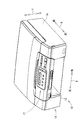
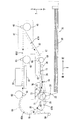
図1に示されるように、複合機10は、薄型の直方体に概ね形成されており、下部にインクジェット記録方式のプリンタ部11が設けられている。複合機10は、ファクシミリ機能及びプリント機能などの各種の機能を有している。プリント機能としては、記録用紙の両面に画像を記録する両面画像記録機能を有している。なお、プリント機能以外の機能の有無は任意である。プリンタ部11は、正面に開口13が形成されたケーシング(筐体)14を有し、各種サイズの記録用紙(本発明のシートの一例)を載置可能なトレイ20(本発明のトレイの一例)を備えた給紙カセット78が、開口13から前後方向8に挿抜可能である。複合機10の正面上部には、操作パネル17が設けられている。操作パネル17は、プリンタ部11を操作するための装置である。複合機10は、操作パネル17からの操作入力に基づいて動作する。
As shown in FIG. 1, the
[プリンタ部11の構成]
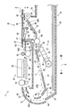
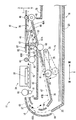
次に、図2が参照されながら、プリンタ部11の構成が説明される。なお、図2では、給紙カセット78の前方側(紙面右側)の図示が省略されている。プリンタ部11は、トレイ20から記録用紙をピックアップして給紙(給送)する給紙部15(本発明の給紙部の一例)と、給紙部15によって給紙された記録用紙にインク滴を吐出して記録用紙に画像を記録するインクジェット記録方式の記録部24(本発明の記録部の一例)と、経路切換部41などを備えている。なお、記録部24はインクジェット方式に限られず、電子写真方式などの種々の記録方式のものが適用可能である。
[Configuration of Printer Unit 11]
Next, the configuration of the
[搬送路65]
プリンタ部11の内部には、トレイ20の先端(後方側の端部)から記録部24を経て排紙保持部79に至る搬送路65が形成されている。搬送路65は、トレイ20の先端から記録部24に至る間に形成された湾曲路65A(本発明の第1搬送路の一例)と、記録部24から排紙保持部79に至る間に形成された排紙路65Bとに区分される。湾曲路65Aは、トレイ20に設けられた分離傾斜板22(本発明の傾斜板の一例)の上端付近から記録部24に渡って延設された湾曲状の通路である。
[Conveyance path 65]
Inside the
分離傾斜板22は、トレイ20の後端部において左右方向9(図2の紙面に垂直な方向)に渡って後方斜め上方に延設されている。分離傾斜板22とトレイ20におけるシート載置面とがなす角の角度は、シート載置面に載置された記録用紙が湾曲路へ円滑に導かれる角度である。例えば、分離傾斜板22とシート載置面とがなす角の角度は、シート載置面と平行な直線と湾曲路65Aの始端64からの延長戦がなす角の角度の2分の1の角度に設定される。以上より、分離傾斜板22は、シート載置面から湾曲路65Aへの記録用紙の搬送向きに沿ってトレイ20と一体に設けられ、シート載置面と湾曲路65Aとがなす角を緩和する角度の傾斜を構成する。
The separation inclined
湾曲路65Aは、プリンタ部11の内部側を中心とする円弧形状に概ね形成されている。トレイ20から給送される記録用紙は、湾曲路65Aを介して、記録部24へ案内される。湾曲路65Aは、所定間隔を隔てて互いに対向する外側ガイド部材18と内側ガイド部材19とによって区画されている。つまり、外側ガイド部材18と内側ガイド部材19は、本発明の第1ガイド部材の一例である。なお、外側ガイド部材18及び内側ガイド部材19、更に後述する上側ガイド部材82、下側ガイド部材83、上側傾斜ガイド部材32、下側傾斜ガイド部材33、及び支持部材43は、いずれも、図2の紙面垂直方向(図1の左右方向9)へ延出されている。
The
なお、本実施形態において、外側ガイド部材18は、図4に示されるように、基軸84を中心として矢印85の方向に回動する。当該回動は、例えば複合機10のユーザの手動によって行われる。
In the present embodiment, the
排紙路65Bは、記録部24よりも第1搬送向きの下流側から排紙保持部79に渡って延設された直線上の通路である。ここで、第1搬送向きとは、記録用紙が搬送路65を搬送される向き(図2において矢印付きの一点鎖線で示される向き)を指す。
The
記録部24よりも第1搬送向きの下流側に分岐口36が形成されている。両面画像記録の際には、排紙路65Bを搬送される記録用紙は、分岐口36の下流側でスイッチバックされ、後述する反転搬送路67(本発明の第2搬送路の一例)へ向けて搬送される。
A
[記録部24]
記録部24は、トレイ20の上方に配置されている。記録部24は、図2の紙面垂直方向(主走査方向)に往復動する。記録部24の下方には記録用紙を水平に保持するためのプラテン42が設けられている。記録部24は、主走査方向への往復移動過程において、図示しないインクカートリッジから供給されたインクをノズル39からプラテン42上を搬送される記録用紙に吐出する。これにより、記録用紙に画像が記録される。
[Recording unit 24]
The
湾曲路65Aの終端と記録部24との間には、第1搬送ローラ60及びピンチローラ61が設けられている。ピンチローラ61は、図示しないバネなどの弾性部材によって第1搬送ローラ60のローラ面に圧接されている。第1搬送ローラ60及びピンチローラ61は、湾曲路65Aを搬送してきた記録用紙を狭持してプラテン42上へ送る。また、記録部24と排紙路65Bの始端との間には、第2搬送ローラ62及び拍車ローラ63が設けられている。ピンチローラ61と同様、拍車ローラ63は第2搬送ローラ62のローラ面に圧接されている。第2搬送ローラ62及び拍車ローラ63は、記録部24によって画像を記録された記録用紙を狭持して第1搬送向きの下流側(排紙保持部79側)へ搬送する。
A
第1搬送ローラ60及び第2搬送ローラ62は、搬送用モータ(不図示)から駆動伝達機構(不図示)を介して回転駆動力が伝達されて回転される。駆動伝達機構は、遊星ギヤなどから構成されており、搬送用モータが正転または逆転のいずれに回転されても、記録用紙を第1搬送向きへ搬送させるべく、第1搬送ローラ60及び第2搬送ローラ62を一回転方向へ回転させる。
The
[給紙部15]
給紙部15は、記録部24の下方であってトレイ20の上方、つまり記録部24とトレイ20の間に設けられている。給紙部15は、トレイ20に収容された記録用紙を湾曲路65Aへ向けて搬送する。給紙部15は、給紙ローラ25(本発明のローラの一例)と、給紙アーム26(本発明のアームの一例)と、駆動伝達機構27とを備えている。
[Paper Feeder 15]
The
給紙ローラ25は、トレイ20に載置されている記録用紙をピックアップして湾曲路65Aへ給紙するものであり、給紙アーム26の先端に回転自在に軸支されている。給紙ローラ25は、搬送用モータとは異なる駆動源のASF(Auto Sheet Feed)モータ(不図示)から駆動伝達機構27を介して回転力が伝達されると回転駆動される。駆動伝達機構27は給紙アーム26に軸支されており、概ね直線状に並ぶ複数のギヤで構成されている。ASFモータは、正転又は逆転の一方に回転され、給紙ローラ25は、ASFモータの回転により、記録用紙を湾曲路65Aへ給紙する向きに回転する。
The
給紙アーム26は、その基端部が基軸28に支持されており、基軸28を中心軸として回動可能である。このため、給紙アーム26は、トレイ20に対して接離可能に上下動することができる。また、給紙アーム26は、自重により又はバネなどの弾性部材による弾性力により、図2の矢印29の方向へ回動付勢されている。このため、給紙ローラ25は、トレイ20に収容された記録用紙の上面に圧接可能である。つまり、給紙部15は、給紙ローラ25がトレイ20における記録用紙が載置されている面(本発明のシート載置面に相当。以下、シート載置面と記す。)に当接する第1姿勢(本発明の第1姿勢に相当)をとる。
The
また、図5及び図6に示されるように、給紙部15は、トレイ20がプリンタ部11に対して挿入される際、またはトレイ20がプリンタ部11から引き抜かれる際に、トレイ20の上面(例えば分離傾斜板22)に押されることによって、上方へ押し上げられる。つまり、給紙部15は、トレイ20が複合機10に対して挿抜される過程において、分離傾斜板22により上方へ押されることによって、シート載置面から離間してトレイ20の挿抜領域から退避する第5姿勢(本発明の第5姿勢に相当)に回動可能である。
As shown in FIGS. 5 and 6, the
なお、給紙部15を押すのは、分離傾斜板22に限らない。例えば、トレイ20の側壁21(図2参照)であってもよいし、トレイ20の側壁21及び分離傾斜板22の双方であってもよい。
The pressing of the
また、上述したように、給紙アーム26は、図2の矢印29の方向へ回動付勢されている。そのため、図4に示されるように、給紙部15は、トレイ20がプリンタ部11から引き抜かれた状態では、トレイ20の下方に配置されている複合機10のフレーム77などに圧接される。つまり、給紙部15は、トレイ20が複合機10から抜かれた状態において、給紙ローラ25が第1姿勢よりも下方となる第2姿勢(本発明の第2姿勢に相当)へ回動可能である。以上より、給紙アーム26は、第1姿勢、第5姿勢、及び第2姿勢との間で回動する。
As described above, the
[経路切換部41]
図2に示されるように、経路切換部41は、搬送路65における分岐口36付近に配置されている。経路切換部41は、第3搬送ローラ45と、拍車ローラ46と、フラップ49で構成されている。
[Route switching unit 41]
As shown in FIG. 2, the
第3搬送ローラ45は、下側ガイド部材83よりも下流側に設けられている。第3搬送ローラ45は、プリンタ部11のフレームなどに回転可能に支持されている。拍車ローラ46は、自重若しくはバネなどによって第3搬送ローラ45のローラ面に圧接されている。
The
第3搬送ローラ45は、搬送用モータから正逆回転方向の駆動力が伝達されて、正逆転いずれかの方向に回転される。例えば、片面記録が行われる場合は、第3搬送ローラ45は正転方向へ回転される。これにより、記録用紙は第3搬送ローラ45及び拍車ローラ46に挟持されて下流側へ搬送され、排紙保持部79に排紙される。一方、両面記録が行われる場合は、第3搬送ローラ45及び拍車ローラ46が記録用紙の後端部を挟持した状態で、第3搬送ローラ45の回転方向が正転から逆転へ切り換えられる。
The
図2の紙面垂直方向(図1の左右方向9)へ延びる支軸87が、プリンタ部11のフレームなどに設けられている。フラップ49は、支軸87から概ね下流側へ延出されている。フラップ49は、支軸87に回動可能に軸支されている。フラップ49には、拍車状に形成された補助ローラ47及び補助ローラ48が軸支されている。
A
フラップ49は、姿勢変化可能に構成されており、下側ガイド部材83よりも上方に位置する排出姿勢(図2に破線で示される姿勢)と、延出端部49Aが分岐口36よりも下方へ進入する反転姿勢(図2に実線で示される姿勢)との間で回動する。記録部24を通過した記録用紙は、フラップ49が排出姿勢の場合、更に第1搬送向きの下流側へ搬送され、フラップ49が反転姿勢の場合、反転搬送路67へスイッチバック搬送される。
The
[反転搬送路67]
反転搬送路67は、搬送路65における記録部24より第1搬送向きの下流側から搬送路65における第1搬送ローラ60より第1搬送向きの上流側へ記録用紙を案内する。反転搬送路67は、分岐口36で排紙路65Bから分岐され、記録部24と給紙アーム27の間を通って、記録部24よりも第1搬送向きの上流側の合流部37で湾曲路65Aと合流する。記録用紙は、反転搬送路67を第2搬送向きに搬送される。ここで、第2搬送向きとは、図2における矢印付きの二点鎖線で示される向きを指す。以上より、反転搬送路67は、記録部24によって少なくとも一方の面に画像が記録された記録用紙を湾曲路65Aへ案内するための経路である。
[Reverse conveying path 67]
The
反転搬送路67は、第1経路67Aと第2経路67Bとに区分される。第1経路67Aは、分岐口36から後方斜め下向きに傾斜する傾斜面を有する上側傾斜ガイド部材32と下側傾斜ガイド部材33とによって区画されている。
The
第2経路67Bは、図5及び図6の矢印30,34に示す方向に回動可能に支持された回動ガイド部材70(本発明の第2ガイド部材の一例)と、プリンタ部11のフレームに取り付けられており、記録部24を支持している支持部材43とによって区画されている。
The
反転搬送路67には、第4搬送ローラ68及び拍車ローラ69が設けられている。拍車ローラ69は、自重若しくはバネなどによって第4搬送ローラ68のローラ面に圧接されている。第4搬送ローラ68は、回転することによって記録用紙を第2搬送向きへ搬送する。第4搬送ローラ68は、搬送用モータから回転力が伝達されて回転駆動される。第4搬送ローラ68の回転の向きは、記録用紙を第2搬送向きへ搬送させる向きである。
In the
[回動ガイド部材70]
回動ガイド部材70は、記録部24と給紙部15の間に設けられている。回動ガイド部材70は、上下方向7の寸法が前後方向8及び左右方向9の寸法よりも短い概ね薄型の平板矩形状の部材である。回動ガイド部材70は、その先端部(後方側の端部)が斜め上向きに湾曲している。これにより、反転搬送路67及び湾曲路65Aは略円弧状の経路を構成し、反転搬送路67を搬送される記録用紙は湾曲路65Aに円滑に導かれる。
[Rotation guide member 70]
The
回動ガイド部材70は、その基端部(前方側の端部)が給紙部15の基軸73に支持されており、基軸73を中心軸として回動可能である。基軸73に支持されることにより、回動ガイド部材70は、記録部24に対して接近及び離間可能に上下動することができる。
The
回動ガイド部材70は、回動することによって、反転搬送路67の少なくとも一部を形成する第3姿勢(本発明の第3姿勢に相当)と、第3姿勢よりも記録部24側へ接近する第6姿勢(本発明の第6姿勢に相当)と、第3姿勢よりも記録部24側から離間する第4姿勢(本発明の第4姿勢に相当)とをとることが可能である。
The
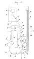
第3姿勢は、図2及び図3に示されるように、回動ガイド部材70の上面が支持部材43と記録用紙が通過可能な所定の間隔を保持する姿勢である。回動ガイド部材70が第3姿勢をとっている場合、回動ガイド部材70はトレイ20の側壁21に支持されている。トレイ20の側壁21は、記録用紙が載置される底板の左右方向9の両端部から前後方向8に沿って立設されている。図2及び図3では、トレイ20の側壁21の上端部が破線で示されている。なお、本実施形態では、回動ガイド部材70の下面から支持部材80が突設されており、支持部材80と側壁21が当接されることで回動ガイド部材70は側壁21に支持されている。なお、図4から図6において、側壁21の図示は省略されている。
As shown in FIGS. 2 and 3, the third posture is a posture in which the upper surface of the
第6姿勢は、図6に示されるように、回動ガイド部材70の下面が給紙部15に押されることによって、回動ガイド部材70の上面が、支持部材43の近傍まで接近する姿勢である。第4姿勢は、図4に示されるように、トレイ20が複合機10から抜かれた際に、回動ガイド部材70の下面がトレイ20の側壁21に支持されなくなることによって、回動ガイド部材70が、給紙部15の第2姿勢への回動に追随して、複合機10のフレーム77の上方近傍まで接近する姿勢である。
As shown in FIG. 6, the sixth posture is a posture in which the upper surface of the
[孔71]
回動ガイド部材70の記録用紙が搬送される面(本発明のシート搬送面に相当。以下、シート搬送面と記す。)には、給紙ローラ25と対向する位置に開口が設けられている。詳細には、図4に示されるように、回動ガイド部材70が第4姿勢をとっている場合に、回動ガイド部材70に開口が設けられていないと給紙ローラ25の少なくとも一部(例えば、給紙ローラ25の給紙アーム26よりも上側のローラ表面)が回動ガイド部材70に当接する位置に、第1の孔71(本発明の第1開口部の一例)が設けられている。
[Hole 71]
An opening is provided on the surface of the
また、図5に示されるように、回動ガイド部材70が第3姿勢をとっている場合に、回動ガイド部材70に開口が設けられていないと給紙ローラ25及び/または給紙アーム26の少なくとも一部(例えば、給紙ローラ25の給紙アーム26よりも上側のローラ面や、給紙アーム26の上面)が回動ガイド部材70に当接する位置に、第2の孔(本発明の第2開口部の一例)が設けられている。
Further, as shown in FIG. 5, when the
なお、本実施形態においては、第1の孔71と第2の孔は共用されており、同一の孔である。しかし、回動ガイド部材70と給紙ローラ25の相対位置関係によっては、回動ガイド部材70が第4姿勢をとる場合と第3姿勢をとる場合とで、給紙ローラ25が回動ガイド部材70に当接する位置が異なる場合がある。その場合、第1の孔と第2の孔は別個に設けられる。以下、第1の孔71と第2の孔が共用された孔は、単に孔71と記される。
In the present embodiment, the
回動ガイド部材70に孔71が設けられることにより、回動ガイド部材70が第4姿勢の状態において、第2姿勢の給紙ローラ25の少なくとも一部が貫通して回動ガイド部材70のシート搬送面より上方へ突出する。また、回動ガイド部材70が第3姿勢の状態において、第5姿勢に回動された給紙部15の少なくとも一部が貫通して回動ガイド部材70のシート搬送面より上方へ突出する。
By providing the
[突起72]
図3に示されるように、給紙アーム26の上面の給紙ローラ25との近傍部分には、突起72が設けられている。図6に示されるように、突起72(本発明のストッパの一例)は、給紙部15が第5姿勢をとっている場合に、回動ガイド部材70の下面と当接している。なお、突起72が設けられる位置は、給紙部15の回動による給紙ローラ25の表面と回動ガイド部材70との接触が防止可能であれば、給紙アーム26の上面に限らない。
[Protrusions 72]
As shown in FIG. 3, a
[板状部材75]
図3に示されるように、回動ガイド部材70の下面における孔71の基軸73側の端部近傍の位置に基軸74が設けられている。また、孔71と略同一形状をした板状部材75(本発明の開閉部材の一例)が、孔71を塞ぐ位置に設けられている。板状部材75は、その基端部が基軸74に支持されており、基軸74を中心軸として回動可能である。
[Plate-like member 75]
As shown in FIG. 3, a
板状部材75は、自重により又はバネなどの弾性部材による弾性力により、下方に回動付勢されている。但し、規制部材(不図示)などによって、孔71を塞ぐ位置(図3に示される位置)より下方には回動されないように構成されている。これにより、図3に示されるように、板状部材75は、給紙部15が第1姿勢をとっている場合、孔71を閉鎖する位置に回動される。その結果、板状部材75は、回動ガイド部材70のシート搬送面の一部を形成する。一方、図6に示されるように、板状部材75は、給紙部15が第5姿勢をとっている場合、給紙ローラ25の表面に押され、孔71を開放する位置に回動される。
The plate-
図3及び図6に基づく上述の説明では、給紙ローラ25のみが孔71を貫通する構成において板状部材75が設けられている場合について説明した。しかし、板状部材75は、給紙ローラ25だけでなく給紙アーム26を含む給紙部15の少なくとも一部が孔71を貫通する場合に設けられてもよい。この場合、板状部材75は、給紙アーム26を含む給紙部15の少なくとも一部が貫通する孔71を塞ぐ位置及び開放する位置に姿勢変化することが可能に構成される。
In the above description based on FIGS. 3 and 6, the case where the plate-
なお、板状部材75は、回動されることによって孔71を塞ぐ位置と開放する位置に姿勢変化するものに限らない。例えば、板状部材75は、回動ガイド部材70のシート搬送面と平行にスライドされることによって姿勢変化するものであってもよい。
Note that the plate-
[弾性部材]
図4に示されるように、回動ガイド部材70の下面(シート搬送面の反対側の面)にはバネなどの弾性部材76(本発明の弾性部材の一例)が設けられている。図4に示されるように、弾性部材76は、回動ガイド部材70が第4姿勢をとった場合に、最も下方に位置する部分に設けられている。そして、回動ガイド部材70が第4姿勢をとった場合に、弾性部材76は複合機10のフレーム77に当接される。なお、図4以外では、弾性部材76の図示が省略されている。
[Elastic member]
As shown in FIG. 4, an elastic member 76 (an example of the elastic member of the present invention) such as a spring is provided on the lower surface (the surface opposite to the sheet conveying surface) of the
[給紙部15及び回動ガイド部材70の回動]
図3に示されるように、記録用紙に画像が記録される処理が実行されているとき、給紙部15は第1姿勢をとっており、回動ガイド部材70は第3姿勢をとっている。上記処理が実行されていないときに、トレイ20が複合機10から抜かれる過程において、回動ガイド部材70は、給紙部15の第1姿勢から第5姿勢への回動に連動して、第3姿勢から第6姿勢へ回動される。その後、トレイ20が複合機10から抜かれると、給紙部15が第5姿勢から第2姿勢へ回動され、回動ガイド部材70が第6姿勢から第4姿勢へ回動される。
[Rotation of
As shown in FIG. 3, when the process of recording an image on the recording paper is being performed, the
以下に詳述する。図3に示される状態において、トレイ20がプリンタ部11から引き抜かれる、つまり前方へ移動されると、分離傾斜板22の内側面23が給紙ローラ25に当接しないように、給紙アーム26がトレイ20により上方へ回動し、それに伴い、給紙ローラ25も上方へ回動する。よって、給紙部15が第1姿勢から第5姿勢へ回動する。給紙ローラ25が所定量だけ上方へ回動すると、給紙ローラ25が板状部材75と当接する。
This will be described in detail below. In the state shown in FIG. 3, when the
この状態において、図5に示されるように、トレイ20が更に前方へ移動されることによって、給紙ローラ25が更に上方へ回動すると(図5の矢印30参照)、板状部材75は給紙ローラ25に押されることによって上方へ回動する(図5の矢印31参照)。また、突起72が回動ガイド部材70の下面に当接する。この状態において、給紙ローラ25が更に上方へ回動すると(図6の矢印34参照)、回動ガイド部材70は、突起72に押されることによって、給紙部15と一体に上方へ回動する(図6の矢印35参照)。つまり、本実施形態においては、突起72が、給紙部15の第5姿勢への回動に連動させて回動ガイド部材を第6姿勢へ回動させる本発明の連動部を構成している。
In this state, as shown in FIG. 5, when the
上記の回動は、図6に示されるように、給紙ローラ25が、分離傾斜板の上端と当接するまで継続される。図6の状態では、給紙部15は第5姿勢をとっており、回動ガイド部材70は第6姿勢をとっている。
The above rotation is continued until the
図6において、給紙部15は実線で第5姿勢の状態が示されている。一方、回動ガイド部材70は破線で第3姿勢の状態が示されている。図6から明らかなとおり、給紙部15は、回動ガイド部材70を上方へ押すことによって、それまで第5姿勢をとっていた回動ガイド部材70が存在していた領域で第3姿勢をとる。つまり、給紙部15が第5姿勢をとるための領域と、回動ガイド部材70が第3姿勢をとるための領域とは重なっている。
In FIG. 6, the
また、図6に示されるように、第5姿勢の給紙部15の給紙アーム26は、その長手方向(前後方向8)が第6姿勢の回動ガイド部材70のシート搬送面と略平行となるように配置されている。
Further, as shown in FIG. 6, the
図6の状態において、トレイ20が複合機10から完全に引き抜かれると、給紙部15はトレイ20及び分離傾斜板22によって支持されていない状態となる。すると、図2の矢印29の方向へ回動付勢されている給紙部15は、下方へ移動される。この際、図4に示されるように、給紙ローラ25の下面は、それまで存在していたトレイ20のシート載置面の高さよりも更に低い位置である第2姿勢に回動される。
In the state of FIG. 6, when the
[実施形態の効果]
回動ガイド部材70は、トレイ20が複合機10から抜かれると第4姿勢に回動される。これにより、記録部24と回動ガイド部材70の間の空間が大きくなる。したがって、外側ガイド部材18が複合機10に対して開閉可能に構成されることにより、回動ガイド部材70において記録用紙が詰まっても、記録用紙を容易に取り出すことができる。しかし、上記のように回動ガイド部材70が第4姿勢に回動されると、給紙ローラ25へのアクセスは回動ガイド部材70によって阻害される。
[Effect of the embodiment]
The
しかし、上述の実施形態によれば、回動ガイド部材70に孔71が設けられている。そして、回動ガイド部材70が第4姿勢に回動されると、給紙ローラ25の少なくとも一部が孔71を貫通して回動ガイド部材70のシート搬送面より上方へ突出する。これにより、給紙ローラ25へのアクセスが回動ガイド部材70によって阻害されなくなる。したがって、給紙ローラ25の清掃を容易に行うことができる。
However, according to the above-described embodiment, the
トレイ20が複合機10に対して挿抜されるとき、給紙部15がトレイ20、分離傾斜板22、またはトレイ20及び分離傾斜板22の双方に当たると、トレイ20の挿抜が適切に実行できない。このような問題を解決するためには、トレイ20の挿抜の際に、給紙部15がトレイ20より上方に退避するように、複合機10が構成されればよい。上述の実施形態においては、給紙部15はトレイ20より上方の第5姿勢に退避することが可能である。しかし、複合機10が上述のように構成された場合、給紙部15を退避させるための空間が、複合機10の内部に必要となる。その結果、複合機10が大型化してしまう。
When the
しかし、上述の実施形態においては、トレイ20が複合機10に対して挿抜される過程において、給紙部15が第1姿勢から第5姿勢へ回動されたとき、給紙部15の少なくとも一部が、孔71を貫通して回動ガイド部材70のシート搬送面より上方へ突出する。これにより、給紙部15を退避させるための空間が、回動ガイド部材70のシート搬送面の上方の空間と共用されることが可能となる。したがって、給紙部15の退避領域を確保しつつ、複合機10が小型化できる。
However, in the above-described embodiment, when the
給紙ローラ25の表面が回動ガイド部材70と接触すると、給紙ローラ25の表面が傷つくおそれがある。しかし、上述の実施形態においては、突起72によって給紙ローラ25の表面と回動ガイド部材70との接触が防止可能である。また、上述の実施形態においては、突起72が、給紙ローラ25の表面と回動ガイド部材70との接触を防止するストッパとしての役割を果たしつつ、給紙部15の第5姿勢への回動に連動させて回動ガイド部材70を第6姿勢へ回動する。これにより、給紙ローラ25の表面と回動ガイド部材70との接触を防止する機構が、給紙部15の回動に連動させて回動ガイド部材70を回動させる機構と別個に設けられる構成に比べて、複合機10内に配置される構成要素を少なくすることができる。その結果、複合機10が小型化できる。
If the surface of the
上述の実施形態においては、給紙アーム26の長手方向と回動ガイド部材70のシート搬送面とが平行とされている。これにより、給紙アーム26と回動ガイド部材70の間隔が小さくできる。したがって、複合機10が小型化できる。
In the above-described embodiment, the longitudinal direction of the
回動ガイド部材70に孔71が設けられていると、記録用紙が孔71に引っ掛かり詰まるおそれがある。これを防止するためには、記録用紙をシート搬送面上の孔71に誘導されないための部材が回動ガイド部材70に設けられればよい。このような部材としては、例えば孔71の周囲に沿って設けられた凸部がある。しかし、当該凸部が設けられることによって、回動ガイド部材70の厚みが増加する。その結果、複合機10が大型化される。そこで、上述の実施形態においては、記録用紙が反転搬送路67を搬送される状態において、孔71を閉鎖する板状部材75が設けられている。これにより、回動ガイド部材70の厚みを増加させることなく、記録用紙が孔71に引っ掛かり詰まってしまうことが低減可能である。
If the
上述の実施形態のように、回動ガイド部材70が第4姿勢に回動されたときに給紙ローラ25の少なくとも一部が貫通される孔と、回動ガイド部材70が第3姿勢に回動されたときに給紙部15の少なくとも一部が貫通される孔とが共用されることによって、回動ガイド部材70に設けられる孔71の個数や面積が減少可能である。これにより、記録用紙が孔71に引っ掛かり詰まってしまうことが低減可能である。
As in the above-described embodiment, when the
トレイ20が複合機10から抜かれると、回動ガイド部材70が第4姿勢に回動される。このとき、回動ガイド部材70は、トレイ20の下方に存在する複合機10の底面を構成する筐体などに接触して大きな音を立てるおそれがある。しかし、上述の実施形態においては、弾性部材76によって、回動ガイド部材70と着地面との接触時の衝撃が緩和される。これにより、回動ガイド部材70が着地面と接触する際の音を小さくできる。
When the
[実施形態の変形例1]
上述の実施形態においては、突起72が本発明の連動部である場合について説明したが、連動部は突起72に限らない。例えば、給紙アーム26が連動部であってもよい。この場合、給紙アーム26が回動すると、突起72ではなく給紙アーム26が回動ガイド部材70の下面に当接する。そして、この状態において、給紙部15が更に上方へ回動すると、回動ガイド部材70は、給紙アーム26に押され、給紙部15と一体に上方へ回動する。
[Modification 1 of Embodiment]
In the above-described embodiment, the case where the
本実施形態においては、回動ガイド部材70は、第6姿勢をとることによって、自身と記録部24との間に存在する空間に配置される。よって、給紙部15は、それまで回動ガイド部材70が存在していた空間に存在することができる。したがって、給紙部15の退避領域を確保しつつ、複合機10が小型化できる。
In the present embodiment, the
[実施形態の変形例2]
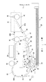
上述の実施形態においては、反転搬送路67の少なくとも一部を構成する部材として、回動可能な回動ガイド部材70が複合機10に設けられている場合について説明した。しかし、反転搬送路67の少なくとも一部を構成する部材は、回動されない固定の部材であってもよい。例えば、図7に示されるように、反転搬送路67の下側は回動されない下側ガイド部材33(本発明の請求項10の第2ガイド部材の一例)のみで構成されてもよい。この場合、反転搬送路67は、上側に配置された上側ガイド部材32及び支持部材43と、下側に配置された下側ガイド部材33とによって区画される。
[Modification 2 of the embodiment]
In the above-described embodiment, a case has been described in which the
このような構成の場合、給紙部15は、給紙ローラ25がトレイ20のシート載置面に当接する第1姿勢(本発明の請求項10の第1姿勢に相当。図7において破線で示される姿勢)と、シート載置面から離間する第7姿勢(本発明の請求項10の第2姿勢に相当。図7において実線で示される姿勢)に回動可能である。当該回動は、上述の実施形態における第1姿勢から第5姿勢への回動と同様にして実行される。また、下側ガイド部材33の記録用紙が搬送される面(本発明の請求項10のシート搬送面に相当)には、第7姿勢に回動された給紙部15の少なくとも一部が貫通して下側ガイド部材33の上面より上方へ突出する第3の孔81(本発明の請求項10の第3開口部の一例)が設けられている。第3の孔81の役割は上述の実施形態における孔71と同様である。
In the case of such a configuration, the
例えば、トレイ20が複合機10に対して挿抜されるときに、給紙部15がトレイ20の側板などに当たると、トレイ20の挿抜が適切に実行できない。このような問題を解決するためには、トレイ20の挿抜の際に、給紙部15がトレイ20より上方に退避するように、複合機10が構成されればよい。本実施形態においては、給紙部15はトレイ20より上方の第7姿勢をとることが可能である。しかし、複合機10が上述のように構成された場合、給紙部15を退避させるための空間が、複合機10の内部に必要となる。その結果、複合機10が大型化してしまう。
For example, when the
しかし、本実施形態においても上述の実施形態と同様に、給紙部15を退避させるための空間が、下側ガイド部材33のシート搬送面の上方の空間と共用されることが可能となる。したがって、給紙部15の退避領域を確保しつつ、複合機10が小型化できる。
However, in this embodiment as well, as in the above-described embodiment, the space for retracting the
10:複合機
15:給紙部
20:トレイ
22:分離傾斜板
24:記録部
70:回動ガイド部材
71:孔
72:突起
75:板状部材
76:弾性部材
10: MFP 15: paper feed unit 20: tray 22: separation inclined plate 24: recording unit 70: rotation guide member 71: hole 72: projection 75: plate member 76: elastic member
Claims (10)
上記記録部の下方に設けられ、シートが載置可能であり、且つ装置に対して挿抜可能であるトレイと、
上記トレイから給送されるシートを上記記録部へ案内する湾曲状の第1搬送路を形成する第1ガイド部材と、
上記記録部と上記トレイの間に設けられ、回動可能なアーム、及び上記アームの先端側に回転可能に設けられて上記トレイに載置されたシートを上記第1搬送路へ供給するローラで構成され、上記ローラが上記トレイのシート載置面に当接する第1姿勢と、上記トレイが装置から抜かれた状態において、上記ローラが上記第1姿勢よりも下方となる第2姿勢との間で回動可能な給紙部と、
上記記録部と上記給紙部の間に設けられ、一方の面に画像が記録されたシートを上記第1搬送路へ案内するための第2搬送路の少なくとも一部を形成する第3姿勢と、上記トレイが装置から抜かれた状態において、上記第3姿勢よりも上記記録部と離間する第4姿勢との間で回動可能な第2ガイド部材と、
上記第2ガイド部材のシート搬送面に開口され、上記第2ガイド部材が上記第4姿勢の状態において、上記第2姿勢の上記ローラの少なくとも一部が貫通して上記シート搬送面より上方へ突出する第1開口部と、を備えた画像記録装置。 A recording unit for recording an image on a sheet;
A tray provided below the recording unit, on which a sheet can be placed, and which can be inserted into and removed from the apparatus;
A first guide member that forms a curved first conveyance path for guiding a sheet fed from the tray to the recording unit;
A rotatable arm provided between the recording unit and the tray, and a roller that is rotatably provided at a tip end side of the arm and supplies a sheet placed on the tray to the first conveyance path; Between a first posture in which the roller contacts the sheet placement surface of the tray and a second posture in which the roller is lower than the first posture in a state where the tray is removed from the apparatus. A rotatable paper feeder;
A third posture which is provided between the recording unit and the paper feeding unit and forms at least a part of a second conveyance path for guiding a sheet having an image recorded on one surface thereof to the first conveyance path; A second guide member rotatable in a state where the tray is removed from the apparatus, and a fourth posture that is separated from the recording unit rather than the third posture;
Opened in the sheet conveying surface of the second guide member, and when the second guide member is in the fourth posture, at least a part of the roller in the second posture penetrates and protrudes upward from the sheet conveying surface. An image recording apparatus.
上記トレイが装置に対して挿抜される過程において、上記給紙部は上記トレイまたは上記傾斜板または双方により上方へ押されることによって、上記シート載置面から離間して上記トレイの挿抜領域から退避する第5姿勢に回動可能であり、
上記第2ガイド部材のシート搬送面に開口され、上記第2ガイド部材が上記第3姿勢の状態において、上記第5姿勢に回動された上記給紙部の少なくとも一部が貫通して上記シート搬送面より上方へ突出する第2開口部を備えた請求項1に記載の画像記録装置。 Provided integrally with the tray along the conveyance direction of the sheet from the sheet placement surface to the first conveyance path, and inclined at an angle that relaxes the angle formed by the sheet placement surface and the first conveyance path. Further comprising an inclined plate,
In the process of inserting / removing the tray with respect to the apparatus, the paper feeding unit is pushed upward by the tray or the inclined plate or both, and is separated from the sheet placing surface and retracted from the tray insertion / extraction region. Is pivotable to a fifth posture,
When the second guide member is opened to the sheet conveyance surface and the second guide member is in the third posture, at least a part of the sheet feeding unit rotated to the fifth posture passes through the sheet. The image recording apparatus according to claim 1, further comprising a second opening projecting upward from the conveyance surface.
上記給紙部の上記第5姿勢への回動に連動させて上記第2ガイド部材を上記第6姿勢へ回動する連動部を備えた請求項2または3に記載の画像記録装置。 The second guide member is rotatable to a sixth posture that is closer to the recording unit than the third posture, the region for the paper feeding unit to take the fifth posture, and the second guide. The member overlaps the region for taking the third posture,
4. The image recording apparatus according to claim 2, further comprising an interlocking unit that rotates the second guide member to the sixth posture in conjunction with the rotation of the paper feeding unit to the fifth posture. 5.
上記給紙部に設けられ、上記給紙部の上記第5姿勢への回動に連動させて上記第2ガイド部材を上記第6姿勢へ回動するとともに、上記給紙部が上記第5姿勢の状態において、上記第2ガイド部と当接することで、上記ローラの表面が上記第2ガイド部材と接触することを防止する連動部を備えた請求項2に記載の画像記録装置。 The second guide member is rotatable to a sixth posture that is closer to the recording unit than the third posture, the region for the paper feeding unit to take the fifth posture, and the second guide. The member overlaps the region for taking the third posture,
The second guide member is rotated to the sixth posture in conjunction with the rotation of the paper feeding portion to the fifth posture, and the paper feeding portion is moved to the fifth posture. 3. The image recording apparatus according to claim 2, further comprising an interlocking unit that prevents the surface of the roller from contacting the second guide member by contacting the second guide unit in the state.
上記記録部の下方に設けられ、シートが載置可能であり、且つ装置に対して挿抜可能であるトレイと、
上記トレイから給送されるシートを上記記録部へ案内する湾曲状の第1搬送路を形成する第1ガイド部材と、
上記記録部と上記トレイの間に設けられ、回動可能なアーム、及び上記アームの回動先端に回転可能に設けられて上記トレイに載置されたシートを上記第1搬送路へ供給するローラで構成され、上記ローラが上記トレイのシート載置面に当接する第1姿勢と上記シート載置面から離間する第2姿勢との間で回動可能な給紙部と、
上記記録部と上記給紙部の間に設けられ、一方の面に画像が記録されたシートを上記第1搬送路へ案内するための第2搬送路の少なくとも一部を形成する第2ガイド部材と、
上記第2ガイド部材のシート搬送面に開口され、上記第2姿勢に回動された上記給紙部の少なくとも一部が貫通して上記第2ガイド部材の上面より上方へ突出する第3開口部と、を備えた画像記録装置。 A recording unit for recording an image on a sheet;
A tray provided below the recording unit, on which a sheet can be placed, and which can be inserted into and removed from the apparatus;
A first guide member that forms a curved first conveyance path for guiding a sheet fed from the tray to the recording unit;
A rotatable arm provided between the recording unit and the tray, and a roller that is rotatably provided at a rotating tip of the arm and supplies a sheet placed on the tray to the first conveyance path A sheet feeding unit that is rotatable between a first posture in which the roller abuts on a sheet placing surface of the tray and a second posture that is separated from the sheet placing surface;
A second guide member provided between the recording unit and the sheet feeding unit and forming at least a part of a second conveyance path for guiding a sheet having an image recorded on one surface thereof to the first conveyance path When,
A third opening that is open on the sheet conveyance surface of the second guide member and that protrudes upward from the upper surface of the second guide member through which at least a part of the sheet feeding unit rotated to the second posture passes. And an image recording apparatus.
Priority Applications (12)
| Application Number | Priority Date | Filing Date | Title |
|---|---|---|---|
| JP2009299273A JP5321447B2 (en) | 2009-12-29 | 2009-12-29 | Image recording device |
| US12/892,390 US8768235B2 (en) | 2009-12-29 | 2010-09-28 | Double-sided image recording device having a compact form factor |
| US14/319,413 US9045302B2 (en) | 2009-12-29 | 2014-06-30 | Image recording device having a compact form factor |
| US14/319,523 US9051144B2 (en) | 2009-12-29 | 2014-06-30 | Double-sided image recording device having a compact form factor |
| US14/727,290 US9283778B2 (en) | 2009-12-29 | 2015-06-01 | Image recording device having a compact form factor |
| US14/949,251 US9452619B2 (en) | 2009-12-29 | 2015-11-23 | Image recording device having a compact form factor |
| US14/949,233 US9440460B2 (en) | 2009-12-29 | 2015-11-23 | Image recording device with a sheet feeder that contacts a duplex return guide |
| US15/276,206 US10086629B2 (en) | 2009-12-29 | 2016-09-26 | Image recording device having a compact form factor |
| US16/134,477 US10414174B2 (en) | 2009-12-29 | 2018-09-18 | Image recording device having a compact form factor |
| US16/544,340 US11077678B2 (en) | 2009-12-29 | 2019-08-19 | Image recording device having a compact form factor |
| US17/380,480 US11890862B2 (en) | 2009-12-29 | 2021-07-20 | Image recording device having a compact form factor |
| US18/543,607 US12162268B2 (en) | 2009-12-29 | 2023-12-18 | Image recording device having a compact form factor |
Applications Claiming Priority (1)
| Application Number | Priority Date | Filing Date | Title |
|---|---|---|---|
| JP2009299273A JP5321447B2 (en) | 2009-12-29 | 2009-12-29 | Image recording device |
Related Child Applications (1)
| Application Number | Title | Priority Date | Filing Date |
|---|---|---|---|
| JP2013149146A Division JP5655906B2 (en) | 2013-07-18 | 2013-07-18 | Image recording device |
Publications (2)
| Publication Number | Publication Date |
|---|---|
| JP2011136831A true JP2011136831A (en) | 2011-07-14 |
| JP5321447B2 JP5321447B2 (en) | 2013-10-23 |
Family
ID=44348663
Family Applications (1)
| Application Number | Title | Priority Date | Filing Date |
|---|---|---|---|
| JP2009299273A Active JP5321447B2 (en) | 2009-12-29 | 2009-12-29 | Image recording device |
Country Status (1)
| Country | Link |
|---|---|
| JP (1) | JP5321447B2 (en) |
Cited By (2)
| Publication number | Priority date | Publication date | Assignee | Title |
|---|---|---|---|---|
| JP5454728B1 (en) * | 2013-07-25 | 2014-03-26 | パナソニック株式会社 | Image forming apparatus |
| US8919531B2 (en) | 2012-04-23 | 2014-12-30 | Brother Kogyo Kabushiki Kaisha | Image recording apparatus |
Citations (2)
| Publication number | Priority date | Publication date | Assignee | Title |
|---|---|---|---|---|
| JP2002362766A (en) * | 2001-06-01 | 2002-12-18 | Canon Inc | Double-sided image forming device |
| JP2009023831A (en) * | 2007-07-24 | 2009-02-05 | Brother Ind Ltd | Image recording device |
-
2009
- 2009-12-29 JP JP2009299273A patent/JP5321447B2/en active Active
Patent Citations (2)
| Publication number | Priority date | Publication date | Assignee | Title |
|---|---|---|---|---|
| JP2002362766A (en) * | 2001-06-01 | 2002-12-18 | Canon Inc | Double-sided image forming device |
| JP2009023831A (en) * | 2007-07-24 | 2009-02-05 | Brother Ind Ltd | Image recording device |
Cited By (3)
| Publication number | Priority date | Publication date | Assignee | Title |
|---|---|---|---|---|
| US8919531B2 (en) | 2012-04-23 | 2014-12-30 | Brother Kogyo Kabushiki Kaisha | Image recording apparatus |
| JP5454728B1 (en) * | 2013-07-25 | 2014-03-26 | パナソニック株式会社 | Image forming apparatus |
| US9250598B2 (en) | 2013-07-25 | 2016-02-02 | Panasonic Intellectual Property Management Co., Ltd. | Image forming apparatus with an arc-shaped duplex feed path having increased radius of curvature |
Also Published As
| Publication number | Publication date |
|---|---|
| JP5321447B2 (en) | 2013-10-23 |
Similar Documents
| Publication | Publication Date | Title |
|---|---|---|
| JP5316404B2 (en) | Image recording device | |
| US10221024B2 (en) | Sheet transport apparatus and image recording apparatus | |
| JP5545058B2 (en) | Image recording device | |
| JP4609579B2 (en) | Image recording device | |
| JP7713921B2 (en) | Image Recording Device | |
| JP2011157155A (en) | Image recording device | |
| JP7347617B2 (en) | image recording device | |
| JP6002375B2 (en) | Image recording device | |
| JP2012091489A (en) | Image recording apparatus | |
| JP5321447B2 (en) | Image recording device | |
| JP5655906B2 (en) | Image recording device | |
| JP5664083B2 (en) | Image recording device | |
| JP5126147B2 (en) | Image recording device | |
| JP6361760B2 (en) | Image recording device | |
| JP6098961B2 (en) | Image recording device | |
| JP6658807B2 (en) | Image recording device | |
| JP5888396B2 (en) | Image recording device | |
| JP6447664B2 (en) | Image recording device | |
| JP5240127B2 (en) | Image recording device | |
| JP5617967B2 (en) | Image recording device | |
| JP5874779B2 (en) | Image recording device | |
| JP2024002049A (en) | image recording device | |
| JP6156525B2 (en) | Image recording device | |
| JP2012152917A (en) | Image recording apparatus | |
| JP5549016B2 (en) | Image recording device |
Legal Events
| Date | Code | Title | Description |
|---|---|---|---|
| A621 | Written request for application examination |
Free format text: JAPANESE INTERMEDIATE CODE: A621 Effective date: 20120130 |
|
| A977 | Report on retrieval |
Free format text: JAPANESE INTERMEDIATE CODE: A971007 Effective date: 20130218 |
|
| A131 | Notification of reasons for refusal |
Free format text: JAPANESE INTERMEDIATE CODE: A131 Effective date: 20130226 |
|
| A521 | Written amendment |
Free format text: JAPANESE INTERMEDIATE CODE: A523 Effective date: 20130419 |
|
| TRDD | Decision of grant or rejection written | ||
| A01 | Written decision to grant a patent or to grant a registration (utility model) |
Free format text: JAPANESE INTERMEDIATE CODE: A01 Effective date: 20130618 |
|
| A61 | First payment of annual fees (during grant procedure) |
Free format text: JAPANESE INTERMEDIATE CODE: A61 Effective date: 20130701 |
|
| R150 | Certificate of patent or registration of utility model |
Ref document number: 5321447 Country of ref document: JP Free format text: JAPANESE INTERMEDIATE CODE: R150 Free format text: JAPANESE INTERMEDIATE CODE: R150 |