JP2011136830A - Image recording device - Google Patents
Image recording device Download PDFInfo
- Publication number
- JP2011136830A JP2011136830A JP2009299266A JP2009299266A JP2011136830A JP 2011136830 A JP2011136830 A JP 2011136830A JP 2009299266 A JP2009299266 A JP 2009299266A JP 2009299266 A JP2009299266 A JP 2009299266A JP 2011136830 A JP2011136830 A JP 2011136830A
- Authority
- JP
- Japan
- Prior art keywords
- tray
- guide plate
- paper feed
- image recording
- roller
- Prior art date
- Legal status (The legal status is an assumption and is not a legal conclusion. Google has not performed a legal analysis and makes no representation as to the accuracy of the status listed.)
- Pending
Links
- 238000004140 cleaning Methods 0.000 claims abstract description 30
- 238000000034 method Methods 0.000 claims description 8
- 230000001105 regulatory effect Effects 0.000 claims description 5
- 238000003780 insertion Methods 0.000 claims description 3
- 230000037431 insertion Effects 0.000 claims description 3
- 230000001276 controlling effect Effects 0.000 claims description 2
- 238000000605 extraction Methods 0.000 claims description 2
- 230000006870 function Effects 0.000 description 12
- 238000000926 separation method Methods 0.000 description 9
- 230000005540 biological transmission Effects 0.000 description 6
- 230000004308 accommodation Effects 0.000 description 2
- 230000000694 effects Effects 0.000 description 2
- 238000005304 joining Methods 0.000 description 2
- 239000000463 material Substances 0.000 description 2
- 239000011347 resin Substances 0.000 description 2
- 229920005989 resin Polymers 0.000 description 2
- 238000011109 contamination Methods 0.000 description 1
- 239000007799 cork Substances 0.000 description 1
- 238000005520 cutting process Methods 0.000 description 1
- 238000010586 diagram Methods 0.000 description 1
- 230000004048 modification Effects 0.000 description 1
- 238000012986 modification Methods 0.000 description 1
- 239000004745 nonwoven fabric Substances 0.000 description 1
- 238000003825 pressing Methods 0.000 description 1
- 229910052710 silicon Inorganic materials 0.000 description 1
- 239000010703 silicon Substances 0.000 description 1
Images


Landscapes
- Feeding Of Articles By Means Other Than Belts Or Rollers (AREA)
- Sheets, Magazines, And Separation Thereof (AREA)
Abstract
【課題】画像記録部とトレイとの間に設けられた搬送路でシート部材が詰まった場合でも、シート部材を容易に除去することが可能であり、且つ、上記搬送路を形成するガイド部材と協働して給送ローラに付着した汚れを容易に除去することが可能な手段を提供する。
【解決手段】画像記録部24と給紙トレイ78との間に下側ガイド部材90が設けられている。下側ガイド部材90は、下面にクリーニングパッド70が取り付けられた後方ガイド板92を有する。後方ガイド板92の前方端は基軸28によって軸支されている。基軸28に給紙アーム26が軸支され、その先端に給紙ローラ25が軸支され、この給紙ローラ25は後方ガイド板92の下側に配置されている。給紙トレイ78の装着状態において後方ガイド板92は給紙ローラ25から離間し、給紙トレイ78の脱抜状態において後方ガイド板92が下降してクリーニングパッド70が給紙ローラ25に接触する。
【選択図】図2A guide member that can easily remove a sheet member even when the sheet member is jammed in a conveyance path provided between an image recording unit and a tray, and that forms the conveyance path Provided is a means capable of easily removing dirt adhered to the feeding roller in cooperation.
A lower guide member 90 is provided between an image recording unit 24 and a paper feed tray 78. The lower guide member 90 includes a rear guide plate 92 having a cleaning pad 70 attached to the lower surface. The front end of the rear guide plate 92 is supported by the base shaft 28. A paper feed arm 26 is pivotally supported on the base shaft 28, and a paper feed roller 25 is pivotally supported at the tip thereof. The paper feed roller 25 is disposed below the rear guide plate 92. When the paper feed tray 78 is attached, the rear guide plate 92 is separated from the paper feed roller 25, and when the paper feed tray 78 is removed, the rear guide plate 92 is lowered and the cleaning pad 70 contacts the paper feed roller 25.
[Selection] Figure 2
Description
本発明は、シート部材の両面に画像を記録する画像記録装置に関し、特に、画像記録部を通過したシート部材をスイッチバックさせて再び画像記録部へ戻す搬送路を有する画像記録装置に関する。 The present invention relates to an image recording apparatus that records images on both sides of a sheet member, and more particularly, to an image recording apparatus having a conveyance path that switches back a sheet member that has passed through an image recording unit and returns it to the image recording unit.
従来より、記録用紙(シート部材)の両面に画像を記録可能な画像記録装置が知られている。特許文献1及び特許文献2には、装置のコンパクト化を実現するために、シートトレイの上側に画像記録部が設けられ、シートトレイと画像記録部とが湾曲状の搬送路で接続された画像記録装置が開示されている。この種の画像記録装置では、両面画像記録を行う場合に、画像記録部を通過した記録用紙をスイッチバックさせて再びシートトレイに搬送し、その記録用紙を給送ローラで再び画像記録部に搬送する機構が採用されている(特許文献1及び2参照)。これにより、シートトレイから給紙するときに通る搬送路をスイッチバック後に案内される搬送経路として兼用できるため、装置の薄型化が実現される。
Conventionally, an image recording apparatus capable of recording images on both sides of a recording sheet (sheet member) is known. In
また、オフィスなどに広く普及している大型で自立型の複写装置(コピー機)では、高さ寸法が制約されないため、給紙時に通る搬送路とは別に、画像記録部とシートトレイとの間にスイッチバック用の搬送路が設けられている。この複写装置では、画像記録部を通過した記録用紙は、スイッチバックされた後に上記スイッチバック用の搬送路を通って再び画像記録部へ搬送される。 In addition, a large and self-supporting copying machine (copier) that is widely used in offices and the like is not limited in height, so that it is located between the image recording unit and the sheet tray separately from the conveyance path through which paper is fed. Is provided with a transport path for switchback. In this copying apparatus, the recording paper that has passed through the image recording section is switched back and then transported again to the image recording section through the switchback transport path.
しかしながら、特許文献1及び2に記載の画像記録装置では、スイッチバック後の記録用紙が給送ローラによって搬送される際に、画像記録面に給送ローラが当接する。そのため、給紙ローラの接触によって画像記録面が汚れるおそれがある。また、画像記録面に付着した記録材(インクやトナー等)が給紙ローラに付着することもあり、この付着した記録材が給紙ローラによって給紙される次の記録用紙に移り、記録用紙を汚すおそれもある。一方、上述した大型の複写装置で採用されているように、給紙時の搬送路とは別の搬送路を設けると上記問題は解決できる。しかしながら、装置の薄型化という社会的要請に応えるために、画像記録部とシートトレイとの間に余分なスペースができないように設計し、装置の高さを限りなくコンパクトにした場合は、仮に上記別の搬送路で記録用紙が詰まると、詰まった記録用紙を除去する作業が極めて困難になる。
However, in the image recording apparatuses described in
そこで、本発明は上記問題に鑑みてなされたものであり、画像記録部とトレイとの間に設けられた搬送路でシート部材が詰まった場合でも、シート部材を容易に除去することが可能であり、且つ、上記搬送路を形成するガイド部材と協働して給送ローラに付着した汚れを容易に除去することが可能な手段を提供することにある。 Therefore, the present invention has been made in view of the above problems, and even when the sheet member is jammed in the conveyance path provided between the image recording unit and the tray, the sheet member can be easily removed. Another object is to provide means capable of easily removing dirt adhering to the feeding roller in cooperation with the guide member forming the conveyance path.
(1) 本発明は、トレイと、画像記録部と、背面カバーと、ガイド部材と、給送ローラと、回動軸と、支持機構と、クリーニング部材とを具備する画像記録装置として構成されている。トレイは、装置本体の正面から該装置本体に対して挿抜可能に設けられている。このトレイに、画像が記録されるシート部材が保持される。画像記録部は、上記トレイの上側に設けられている。背面カバーは、上記装置本体の背面に開閉可能に設けられている。この背面カバーは、装置本体の背面に対して閉じられた状態で上記トレイから上記画像記録部に至る湾曲状の湾曲搬送路を形成し、開けられた状態で上記湾曲搬送路を開放する。ガイド部材は、上記トレイと上記画像記録部との間に設けられている。このガイド部材は第1ガイド板を有している。第1ガイド板は、上記画像記録部を通過した後にガイド部材に搬送されたシート部材を上記湾曲搬送路へ案内する。給送ローラは、上記トレイと上記第1ガイド板との間に設けられている。この給送ローラは、上記トレイに保持されたシート部材を上記湾曲搬送路へ給送する。回動軸は、上記第1ガイド板の背面側の端部を回動自由端として、上記第1ガイド板の下面が上記給送ローラから上方へ離間した第1位置と上記給送ローラに当接する第2位置との間で上記ガイド板を回動自在に支持する。支持機構は、上記トレイが上記装置本体に挿入されたときに上記第1ガイド板を上記第1位置まで持ち上げ、上記トレイが上記装置本体から脱抜されたときに上記第1ガイド板の上記第2位置への回動を許容する。クリーニング部材は、上記第1ガイド板の下面における上記給送ローラとの当接部に設けられており、上記給送ローラと接触することにより上記給送ローラのローラ面の汚れを除去する。 (1) The present invention is configured as an image recording apparatus including a tray, an image recording unit, a back cover, a guide member, a feeding roller, a rotating shaft, a support mechanism, and a cleaning member. Yes. The tray is provided so that it can be inserted into and removed from the apparatus main body from the front of the apparatus main body. A sheet member on which an image is recorded is held on the tray. The image recording unit is provided on the upper side of the tray. The back cover is provided on the back surface of the apparatus main body so as to be opened and closed. The back cover forms a curved curved conveyance path from the tray to the image recording unit in a state of being closed with respect to the back surface of the apparatus main body, and opens the curved conveyance path in an opened state. The guide member is provided between the tray and the image recording unit. The guide member has a first guide plate. The first guide plate guides the sheet member conveyed to the guide member after passing through the image recording unit to the curved conveyance path. The feeding roller is provided between the tray and the first guide plate. The feeding roller feeds the sheet member held on the tray to the curved conveyance path. The pivot shaft has an end on the back side of the first guide plate as a free end of rotation, and the lower surface of the first guide plate is in contact with the feed roller and a first position spaced upward from the feed roller. The guide plate is rotatably supported between the second position and the second position. The support mechanism lifts the first guide plate to the first position when the tray is inserted into the apparatus main body, and the first guide plate has the first guide plate when the tray is removed from the apparatus main body. Allows rotation to 2 positions. The cleaning member is provided at a contact portion with the feeding roller on the lower surface of the first guide plate, and removes dirt on the roller surface of the feeding roller by contacting with the feeding roller.
このように構成されているため、画像記録部とトレイとの間に、上記ガイド部材によって搬送路(以下「反転搬送路」という。)が形成される。この反転搬送路は、画像記録部を通過したシート部材を湾曲搬送路へ案内するためのものである。トレイが装置本体に装着された状態では、ガイド部材は支持機構によって第1位置で支持されている。トレイが装置本体から抜き出されると、ガイド部材が支持機構によって支持されなくなる。このとき、回動軸を中心にして、第1ガイド板がその自重によって下方へ回動する。これにより、上記反転搬送路の背面側が高さ方向に拡げられる。このため、上記反転搬送路でシート部材が詰まった場合でも、背面カバーを開ければ、詰まったシート部材に容易にアクセスすることができるので、シート部材の除去作業が容易となる。また、第1ガイド板が支持機構によって支持されなくなると、第1ガイド板が上記第1位置から上記第2位置まで回動して、第1ガイド板の下面に設けられたクリーニング部材が給送ローラのローラ面に当接する。このため、シート部材の補給や詰まりを除去するためにトレイが装置本体から抜き出される度に、給送ローラのローラ面がクリーニングされる。なお、クリーニング効果を高めるために、バネなどの付勢部材によって上記第1ガイド板を下方へ付勢するようにしてもよい。 Due to such a configuration, a conveyance path (hereinafter referred to as “reverse conveyance path”) is formed by the guide member between the image recording unit and the tray. This reverse conveyance path is for guiding the sheet member that has passed through the image recording section to the curved conveyance path. When the tray is mounted on the apparatus main body, the guide member is supported at the first position by the support mechanism. When the tray is extracted from the apparatus main body, the guide member is not supported by the support mechanism. At this time, the first guide plate is rotated downward by its own weight around the rotation axis. Thereby, the back side of the reversing conveyance path is expanded in the height direction. For this reason, even when the sheet member is jammed in the reversal conveyance path, the jammed sheet member can be easily accessed by opening the back cover, so that the sheet member can be easily removed. When the first guide plate is not supported by the support mechanism, the first guide plate is rotated from the first position to the second position, and the cleaning member provided on the lower surface of the first guide plate is fed. It contacts the roller surface of the roller. For this reason, the roller surface of the feeding roller is cleaned each time the tray is pulled out of the apparatus main body in order to remove the replenishment or clogging of the sheet member. In order to enhance the cleaning effect, the first guide plate may be biased downward by a biasing member such as a spring.
(2) 本発明の画像記録装置は、アーム部材と、上記トレイに設けれた当接部とを更に備えている。アーム部材は、基端部の回動中心から上記トレイの挿抜経路へ向けて上記装置本体の背面側へ斜め下方へ延出されている。このアーム部材は、その基端部が上記トレイの上側で回動自在に支持されており、その回動端に上記給送ローラが軸支されている。当接部は、上記トレイの背面側の端部に立設されており、上記トレイが上記装置本体に対して挿抜される過程で上記アーム部材に当接する。 (2) The image recording apparatus of the present invention further includes an arm member and a contact portion provided on the tray. The arm member extends obliquely downward toward the back side of the apparatus main body from the rotation center of the base end toward the tray insertion / extraction path. The arm member has a base end portion rotatably supported on the upper side of the tray, and the feeding roller is pivotally supported on the rotating end. The abutting portion is erected on an end portion on the back side of the tray, and abuts on the arm member in the process of inserting and removing the tray from the apparatus main body.
このように構成されているため、上記トレイが上記装置本体に挿入される過程で上記トレイの当接部が上記アーム部材に当接し、アーム部材が下から持ち上げられる。このとき、アーム部材と共に給送ローラも持ち上げられて、給送ローラが上記クリーニング部材に当接する。当接部が給送ローラを通り過ぎて装置本体の背面側の奥部に到達すると、持ち上げられていた給送ローラは、クリーニング部材から離れて下降してトレイの上面に当接する。トレイが装置本体から脱抜される場合は、その過程で当接部によって再び給送ローラ及びアーム部材が持ち上げられて、給送ローラが上記クリーニング部材に当接する。そして、当接部がアーム部材を通り過ぎて更に正面側へ移動すると、持ち上げられていた給送ローラは、クリーニング部材から離れて下降する。このように給送ローラが動作するため、トレイが挿抜される過程においても、一時的に給送ローラのローラ面がクリーニング部材によってクリーニングされる。 With this configuration, the abutting portion of the tray abuts on the arm member in the process of inserting the tray into the apparatus main body, and the arm member is lifted from below. At this time, the feeding roller is lifted together with the arm member, and the feeding roller comes into contact with the cleaning member. When the abutting portion passes through the feeding roller and reaches the back side of the apparatus main body, the feeding roller that has been lifted is moved away from the cleaning member and comes into contact with the upper surface of the tray. When the tray is removed from the apparatus main body, the feeding roller and the arm member are lifted again by the contact portion in the process, and the feeding roller comes into contact with the cleaning member. Then, when the contact portion passes through the arm member and further moves to the front side, the feeding roller that has been lifted is lowered away from the cleaning member. Since the feeding roller operates in this manner, the roller surface of the feeding roller is temporarily cleaned by the cleaning member even in the process of inserting and removing the tray.
(3) 本発明の画像記録装置は、上記給送ローラが上記装置本体の底面から離間した所定位置から上記アーム部材の下方への回動を規制する規制手段と、上記給送ローラの回転を制御する制御部とを更に備える。この構成において、上記制御部は、上記給送ローラに対するクリーニング指示信号が入力されたことを条件に、上記給送ローラを所定の時間だけ回転させる。 (3) In the image recording apparatus of the present invention, the feeding roller regulates the downward rotation of the arm member from a predetermined position separated from the bottom surface of the apparatus main body, and the rotation of the feeding roller. And a control unit for controlling. In this configuration, the control unit rotates the feed roller for a predetermined time on condition that a cleaning instruction signal for the feed roller is input.
これにより、例えば、トレイが装置本体から抜き出されて給送ローラとクリーニング部材とが接触した状態にあるときに、クリーニング指示信号が入力されると、給送ローラがクリーニング部材に接触した状態で空回りする。このため、給送ローラのローラ面の全域がクリーニング部材によってクリーニングされる。 Thus, for example, when a cleaning instruction signal is input when the tray is extracted from the apparatus main body and the feed roller and the cleaning member are in contact with each other, the feed roller is in contact with the cleaning member. I go idle. For this reason, the entire roller surface of the feeding roller is cleaned by the cleaning member.
(4) 上記支持機構の具体的な構成としては、第1係合部と、第1支持部とにより構成された機構が考えられる。第1係合部は、上記第1ガイド板の下面に設けられている。第1支持部は、上記トレイが上記装置本体に装着されたときに上記第1係合部と係合して上記第1ガイド板を下側から持ち上げるように支持する。 (4) As a specific configuration of the support mechanism, a mechanism including a first engagement portion and a first support portion is conceivable. The first engaging portion is provided on the lower surface of the first guide plate. The first support part is engaged with the first engagement part when the tray is mounted on the apparatus main body, and supports the first guide plate to be lifted from below.
本発明によれば、画像記録部とトレイとの間に設けられた搬送路でシート部材が詰まった場合でも、シート部材を容易に除去することが可能となる。また、上記搬送路を形成するガイド部材と協働して給送ローラに付着した汚れを容易に除去することが可能となる。 According to the present invention, even when the sheet member is jammed in the conveyance path provided between the image recording unit and the tray, the sheet member can be easily removed. Further, it is possible to easily remove the dirt adhering to the feeding roller in cooperation with the guide member forming the transport path.
以下、適宜図面を参照して、本発明の好ましい実施形態について説明する。なお、以下に説明される実施形態は本発明の一例にすぎず、本発明の要旨を変更しない範囲で、本発明の実施形態を適宜変更できることは言うまでもない。 Hereinafter, preferred embodiments of the present invention will be described with reference to the drawings as appropriate. The embodiment described below is merely an example of the present invention, and it is needless to say that the embodiment of the present invention can be changed as appropriate without departing from the gist of the present invention.
[複合機10の概略構成]
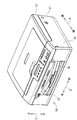
図1は、本発明の画像記録装置の一実施形態である複合機10の外観構成を示す模式斜視図である。なお、以下の説明においては、複合機10が使用可能に設置された状態(図1に示される状態)を基準として上下方向7を定義し、開口13が設けられている側を手前側(正面)として前後方向8を定義し、複合機10を手前側(正面)から見て左右方向9を定義する。
[Schematic configuration of MFP 10]
FIG. 1 is a schematic perspective view showing an external configuration of a
図1に示されるように、複合機10は、高さ(上下方向7の長さ)に対して横幅(左右方向9の長さ)及び奥行き(前後方向8の長さ)が大きい薄型の直方体形状に概ね形成されている。複合機10は、主に、下部に設けられたインクジェット記録方式のプリンタ部11と、上部に設けられたスキャナ部12とを一体的に備えた多機能装置である。複合機10は、ファクシミリ機能、プリント機能、スキャン機能、及び、コピー機能などの各種の機能を有している。プリント機能としては、記録用紙(本発明のシート部材の一例)の表面(第1面)及び裏面(第2面)の両面に画像を記録する両面画像記録機能を有している。なお、プリント機能以外の機能は任意であり、例えば、スキャン機能やコピー機能、ファクシミリ機能を有しないプリンタとして本発明の画像記録装置が実施されてもよい。
As shown in FIG. 1, the
プリンタ部11は、正面に開口13が形成されたプリンタ筐体14(本発明の装置本体の一例)を有する。プリンタ筐体14の内部にプリンタ部11の各構成要素が配置されている。開口13からプリンタ筐体14の内部側へ連続するように収容空間が区画されている。この収容空間に給紙トレイ78(本発明のトレイの一例)が装着されている。給紙トレイ78は、開口13からプリンタ筐体14の内部に対して、前後方向8(水平方向)に挿抜可能に構成されている。給紙トレイ78は、A4サイズの記録用紙(A4用紙)やハガキはなどの各種の記録用紙を保持可能に構成されている。以下、プリンタ部11の構成について詳細に説明する。なお、スキャナ部12の構成についての説明は省略する。
The
[プリンタ部11の構成]
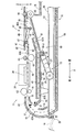
以下、図2を参照しながら、プリンタ部11の構成について詳細に説明する。図2は、プリンタ部11の内部構成を模式的に示す縦断面図である。なお、図2では、前方部分の図示が省略されている。
[Configuration of Printer Unit 11]
Hereinafter, the configuration of the
プリンタ部11は、主として、給紙トレイ78と、給紙トレイ78から記録用紙をピックアップして給紙(給送)する給送部15と、給送部15によって給紙された記録用紙にインク滴を吐出して記録用紙に画像を形成するインクジェット記録方式の画像記録部24(本発明の画像記録部の一例)と、経路切換部41と、外部に排出された記録済みの記録用紙を保持する排紙トレイ79と、プリンタ部11が備える搬送ローラの回転動作等を制御する制御部(本発明の制御部の一例)とを備えている。これらの各構成要素がプリンタ筐体14内に設けられている。なお、画像記録部24は、インクジェット方式に限られず、電子写真方式、或いは感熱記録方式など、種々の記録方式のものが適用可能である。また、排紙トレイ79は、給紙トレイ78と一体に構成されていてもよく、或いはプリンタ筐体14のフレームなどに固定されたものであってもよい。また、上記制御部は、CPUなどの演算素子やROM又はRAMなどの記憶素子を有する周知の演算装置であるため、本明細書では詳細な説明を省略する。
The
[用紙搬送路65]
プリンタ部11の内部には、給紙トレイ78の先端(後方側の端部)から上方手前側へ向かって延出され、画像記録部24を経て排紙トレイ79に至る用紙搬送路65が形成されている。記録用紙が用紙搬送路65を通ることにより、記録用紙が給紙トレイ78から排紙トレイ79まで案内される。用紙搬送路65は、給紙トレイ78の先端から画像記録部24に至る間に形成された湾曲状の湾曲路65A(本発明の湾曲搬送路の一例)と、画像記録部24から排紙トレイ79に至る間に形成された排紙路65Bとに区分される。
[Paper transport path 65]
Inside the
図2に示されるように、湾曲路65Aは、給紙トレイ78に設けられた分離傾斜板22(本発明の当接部の一例)の上端付近から画像記録部24まで延設された湾曲状の通路である。この湾曲路65Aは、プリンタ筐体14の背面側に設けられた背面カバー18(本発明の背面カバーの一例)と、この背面カバー18から前方側へ所定間隔を隔てて互いに対向するように配置された内側ガイド部材19とによって区画されている。背面カバー18及び内側ガイド部材19は、プリンタ部11の内部側を中心とする円弧形状に概ね形成されている。
As shown in FIG. 2, the
背面カバー18は、湾曲路65Aの外側ガイド面を形成するとともに、プリンタ筐体14の背面を形成している。この背面カバー18は、プリンタ筐体14の背面に対して開閉可能に設けられている。詳細には、背面カバー18は、プリンタ筐体14の下部に設けられた支軸20を中心にして、プリンタ筐体14の背面を覆う閉姿勢(図2において実線で示された姿勢)と、プリンタ筐体14から離れて湾曲路65Aを開放する開姿勢(図2において波線で示された姿勢)との間で開閉可能に支持されている。背面カバー18が上記閉姿勢のときに、その内側面によって湾曲路65Aの外側ガイド面が形成される。このような背面カバー18が設けられているため、湾曲路65Aで記録用紙が詰まった場合でも、背面カバー18を開くことによって、詰まった用紙を容易に除去できる。
The
排紙路65Bは、画像記録部24よりも前方側に設けられた上側排紙ガイド82と下側排紙ガイド83とによって区画されている。
The
下側排紙ガイド83の前方側に分岐口36が形成されている。両面画像記録の際には、排紙路65Bを搬送される記録用紙は、分岐口36の下流側でスイッチバックされ、後述する反転搬送路67へ向けて搬送される。
A
[画像記録部24]
画像記録部24は、給紙トレイ78の上側に配置されている。画像記録部24は、図2の紙面垂直方向(左右方向9)に延出されたガイドレール(不図示)に沿って往復動するように構成されている。画像記録部24の下方にプラテン42が設けられている。プラテン42は、画像記録部24によって画像記録が行われる際に、記録用紙を水平に支持するものである。画像記録部24は、主走査方向への往復移動過程において、図示しないインクカートリッジから供給されたインクをノズル39から微小なインク滴としてプラテン42上を搬送される記録用紙に吐出する。これにより、記録用紙に画像が記録される。
[Image Recording Unit 24]
The
用紙搬送路65には、記録用紙を挟持して搬送するための第1搬送ローラ60及び第2搬送ローラ62が設けられている。第1搬送ローラ60と第2搬送ローラ62の間に画像記録部24が設けられている。第1搬送ローラ60にピンチローラ61が圧接されており、第2搬送ローラ62に拍車63が圧接されている。なお、第1搬送ローラ60及び第2搬送ローラ62は、搬送用モータ(不図示)から駆動伝達機構(不図示)を介して回転駆動力が伝達されて回転される。本実施形態では、後述する第3搬送ローラ45を正回転方向又は逆回転方向へ回転させる回転駆動力も上記搬送用モータから供給される。そのため、第1搬送ローラ60及び第2搬送ローラ62への駆動伝達機構として、上記搬送用モータが正回転方向又は逆回転方向のいずれに回転されても、記録用紙を一方向(図2の右側)へ搬送させるべく、遊星ギヤなどによって第1搬送ローラ60及び第2搬送ローラ62を常に一回転方向へ回転させる機構が採用されている。なお、第1搬送ローラ60及び第2搬送ローラ62の駆動源と第3搬送ローラ45の駆動源とが別々に設けられている場合は、上記駆動伝達機構は、上記遊星ギヤを含む構成に限られない。
The
[給送部15]
給送部15は、画像記録部24と給紙トレイ78との間、更に詳細には、後述する下側ガイド部材90と給紙トレイ78との間に設けられている。給送部15は、給紙トレイ78に収容された記録用紙を湾曲路65Aへ向けて搬送するためのものであり、給紙ローラ25(本発明の給送ローラの一例)と、給紙アーム26(本発明のアーム部材の一例)と、駆動伝達機構27とを備えている。
[Feeding unit 15]
The
給紙ローラ25は、給紙トレイ78に保持されて記録用紙を一枚ずつピックアップして湾曲路65Aへ給紙するものである。給紙ローラ25は、記録用紙との接触摩擦を高めるために、シリコンやNBRなどの弾性部材で構成されている。もちろん、樹脂製の給紙ローラ25のローラ面に弾性部材がコーティングされていてもよい。この給紙ローラ25は、給紙アーム26の回動端(先端)に回転自在に軸支されている。給紙ローラ25は、駆動源である給紙用モータ(不図示)の回転力が駆動伝達機構27を介して伝達されることにより、回転駆動される。なお、駆動伝達機構27は、給紙アーム26に軸支されており、給紙アーム26の延出方向に沿って概ね直線状に並ぶ複数のギヤで構成されている。
The
画像記録部24と給紙トレイ78との間に基軸28(本発明の回動軸の一例)が設けられている。給紙アーム26は、その基端部が基軸28に支持されており、基軸28を回動中心として回動可能に構成されている。給紙アーム26は、基軸28の回動中心からプリンタ筐体14の背面側へ斜め下方へ延出されており、その先端は、プリンタ筐体14において給紙トレイ78が挿入される経路、つまり、給紙トレイ78の配置スペースに達している。また、給紙アーム26は、自重により又はバネ等の弾性部材による弾性力により、図2の矢印29の方向へ回動付勢されている。なお、基軸28は、後述する後方ガイド板92を回動自在に支持する回動軸としても兼用されている。
A base shaft 28 (an example of a rotating shaft according to the present invention) is provided between the
このように給紙アーム26が構成されているため、給紙アーム26は、給紙トレイ78に対して接離可能に上下動することができる。給紙トレイ78がプリンタ筐体14に対して挿入されると、その挿入過程において給紙トレイ78の後端に立設された分離傾斜板22が給紙アーム26に当接して給紙アーム26を後方及び上方へ押圧する。これにより、給紙アーム26は上方へ押し上げられる。そして、給紙トレイ78が給紙ローラ25の下側に配置されると、給紙ローラ25は下降して、給紙トレイ78に保持された記録用紙の上面に圧接する。また、給紙トレイ78がプリンタ筐体14から抜き出されると、その脱抜過程において分離傾斜板22の前方側の面が給紙ローラ25に当接して給紙ローラ25と共に給紙アーム26を上方へ押圧する。これにより、給紙アーム26は上方へ押し上げられる。そして、分離傾斜板22が給紙アーム26よりも前方側へ移動すると、給紙ローラ25は下降する。
Since the
なお、プリンタ筐体14のフレームには、給紙トレイ78がプリンタ筐体14から抜き出されても、給紙ローラ25がプリンタ筐体14の底面に接触しないように、規制部材71(図5(D)参照、本発明の規制手段の一例)が設けられている。この規制部材71は、給紙トレイ78の未装着状態において、プリンタ筐体14の底面から離間した所定位置よりも下方へ給紙ローラ25が移動しないように、給紙アーム26に当接して給紙アーム26が下方へ回動しようとするのを規制している。
Note that the regulating member 71 (FIG. 5) prevents the
[給紙トレイ78]
図2に示されるように、給紙トレイ78は、給紙部15の下方に設けられており、プリンタ筐体14の底部に配置されている。
[Paper Tray 78]
As shown in FIG. 2, the
図3は、給紙トレイ78の構成を模式的に示す平面図である。図2及び図3に示されるように、給紙トレイ78は、記録用紙が載置される底板54と、底板54の左右方向9の両端部から上方に立設され、前後方向8に沿って延びる側板55,56と、底板54の後方側の端部に立設され、左右方向9に沿って延びる分離傾斜板22とを備えている。給紙トレイ78は、上面が開放された概ね矩形箱状に構成されている。分離傾斜板22は、記録用紙を円滑に給紙可能なように、後方側へ傾倒している。上述したとおり、記録用紙は、給紙トレイ78の後方側の端部から、当該端部の後方且つ上方の湾曲路65Aへ給送される。
FIG. 3 is a plan view schematically showing the configuration of the
また、給紙トレイ78の左右方向両端部それぞれには一対の支持部57(本発明の第1支持部の一例)が設けられている。この支持部57は、側板55及び側板56それぞれと一体に構成されている。一方の支持部57は、側板55の上端から給紙トレイ78の幅方向中央側へ伸びる板部材であり、他方の支持部57は、側板56の上端から給紙トレイ78の幅方向中央側へ伸びる板部材である。これらの2つの支持部57は、後述する突起102(本発明の第1係合部の一例)と共に、本発明の支持機構を構成する。
In addition, a pair of support portions 57 (an example of the first support portion of the present invention) are provided at both left and right end portions of the
給紙トレイ78の底板54には、前後方向8に沿って延びる一対のサイドガイド75が設けられている。給紙トレイ78には、サイドガイド75を連動させる周知の機構が設けられている。したがって、例えば、一方のサイドガイド75が左右方向9のいずれか一方(右向き)へスライドされると、他方のサイドガイド75がこのスライド動作に連動して、逆向き(左向き)へスライドされる。このため、底板54に載置された記録用紙の幅が一対のサイドガイド75の離間距離と異なる場合は、サイドガイド75を記録用紙の両端に向けてスライドさせることで、記録用紙の幅方向(左右方向9)の中央位置が給紙トレイ78の幅方向の中央に略一致する。このようなサイドガイド75が設けられているため、給紙トレイ78の幅サイズよりも小さいサイズの記録用紙(例えばハガキやL版写真サイズの光沢紙など)が載置されても、その記録用紙を給紙トレイ78の中央に位置決めすることができる。なお、サイドガイドは一つであってもよい。この場合、サイドガイドと側板55,56のいずれかとの間で記録用紙を位置決めすることができる。
The
また、底板54には、前後方向8へスライド可能に支持されたリアガイド77が設けられている。そのため、給紙トレイ78に載置された記録用紙の前方側の端部へ向けてリアガイド77をスライドさせて記録用紙を後方へ押し付けることで、記録用紙を給紙トレイ78の後方側へ詰め寄せることができる。
The
[経路切換部41]
図2に示されるように、経路切換部41は、用紙搬送路65における分岐口36付近に配置されている。経路切換部41は、第3搬送ローラ45と、拍車46と、フラップ49で構成されている。
[Route switching unit 41]
As shown in FIG. 2, the
第3搬送ローラ45は、下側排紙ガイド83よりも下流側に設けられている。第3搬送ローラ45と下側排紙ガイド83との間に分岐口36が形成されている。第3搬送ローラ45は、プリンタ筐体14のフレームなどに回転可能に支持されている。拍車46は、第3搬送ローラ45の上方に配置されており、自重若しくはバネなどによって第3搬送ローラ45のローラ面に圧接されている。拍車46は、上側排紙ガイド82の下流側端部に回転可能の支持されている。第3搬送ローラ45は、搬送用モータから正逆回転方向の駆動力が伝達されて、正回転方向又は逆回転方向に回転駆動される。例えば、片面記録が行われる場合は、第3搬送ローラ45は正回転方向へ回転される。これにより、記録用紙は第3搬送ローラ45及び拍車46に挟持されて前方の排紙トレイ79へ排出される。一方、両面記録が行われる場合は、第3搬送ローラ45及び拍車46が記録用紙の後端部を挟持した状態で、第3搬送ローラ45の回転方向が正回転方向から逆回転方向へ切り換えられる。
The
プリンタ筐体14のフレームなどに、図2の紙面垂直方向(左右方向9)へ延びる支軸87が設けられている。フラップ49は、支軸87から概ね下流側へ延出されている。フラップ49は、支軸87に回動可能に軸支されている。フラップ49には、その延出方向に隔てられた拍車47及び拍車48が軸支されている。フラップ49は、姿勢変化可能に構成されており、下側排紙ガイド83よりも上方に位置する排出姿勢(図2に破線で示される姿勢)と、延出端部49Aが分岐口36よりも下方へ進入する反転姿勢(図2に実線で示される姿勢)との間で回動する。このようなフラップ49が設けられているため、記録用紙の後端がフラップ49を通過してプラップ49が反転姿勢となると、記録用紙の後端が分岐口36の下方へ向けられる。そして、第3搬送ローラが逆回転すると、記録用紙が反転搬送路67へ向けてスイッチバック搬送される。
A
[反転搬送路67]
プリンタ部11の内部には、反転搬送路67が形成されている。反転搬送路67は、排紙路65Bの分岐口36から分岐して、画像記録部24と給紙部15との間を通って後方へ延出され、湾曲路65Aの途中にある合流部37に合流している。反転搬送路67は、前方側の傾斜路67Aと、後方側の直線路67Bとに区分される。経路切換部41でスイッチバック搬送された記録用紙が反転搬送路67を通ることにより、記録用紙が再び湾曲路65Aに戻される。この反転搬送路67は、プリンタ筐体14に固定された上側固定ガイド板43と、後述する下側ガイド部材90(本発明のガイド部材の一例)と、によって形成されている。
[Reverse conveying path 67]
A
[下側ガイド部材90]
図2に示されるように、下側ガイド部材90は、画像記録部24と給紙カセット78との間に設けられており、更に詳細には、給送部15の上側に設けられている。下側ガイド部材90は、基軸28よりも前方側に配置された前方ガイド板91と、基軸28よりも後方側に配置された後方ガイド板92(本発明の第1ガイド板の一例)とにより構成されている。
[Lower guide member 90]
As shown in FIG. 2, the
図4は、下側ガイド部材90の構成を示す模式図であって、(A)には下側ガイド部材90の平面図が示されており、(B)には(A)における切断線IVB−IVBの断面図が示されている。なお、図4では、後方ガイド板92が水平にされた状態が示されている。また、図4(B)では、給紙アーム26の図示が省略されている。前方ガイド板91及び後方ガイド板92は、給紙トレイ78の幅と概ね同じ幅を有する平板状の部材からなる。
4A and 4B are schematic views showing the configuration of the
図4に示されるように、前方ガイド板91は、分岐口36から後方斜め下向きに傾斜する傾斜面を有する。上側固定ガイド43の前方側は、記録用紙が通過可能な所定間隔を隔てて前方ガイド板91に対向するように配置されている。前方ガイド板91と上側固定ガイド43の前方側とによって、反転搬送路67の傾斜路67Aが区画されている。
As shown in FIG. 4, the
後方ガイド板92の前方端おける左右方向両端それぞれに軸受け95が設けられている。この軸受け95に設けられた軸孔(不図示)に基軸28が挿通されている。これにより、後方ガイド板92は、その後方端(背面側の端部)を回動自由端として基軸28を中心に回動可能となる。つまり、後方ガイド板92及び給紙アーム26は、共通の回動軸である基軸28によって回動自在に支持されている。本実施形態では、後述するように、後方ガイド板92の下面が給紙ローラ25から上方へ離間した位置(第1位置、図5(A)参照)と、後方ガイド板92の下面が給紙ローラ25のローラ面に当接する位置(第2位置、図5(B)乃至(C)参照)とを通るように、後方ガイド板92が回動可能となっている。なお、本発明は、後方ガイド板92及び給紙アーム26を基軸28で軸支する構成に限られず、基軸28とは異なる回動軸を設け、この回動軸で後方ガイド板92を回転自在に支持する構成にも適用可能である。
後方ガイド板92の下面に2つの突起102(本発明の第1係合部の一例)が設けられている。突起102は、後方ガイド板92における左右方向両端部それぞれに設けられている。突起102は、後方ガイド板92の下面から下方へ突出している。突起102は、給紙トレイ78がプリンタ筐体14に装着された状態で、上述した支持部57に当接して支持される。これにより、図2に示されるように、基軸28から合流部37までに至る直線路67Bが後方ガイド板92によって形成される。つまり、給紙トレイ78がプリンタ筐体14に装着された状態にあるときに、下側ガイド部材90によって、記録用紙を湾曲路65Aへ案内可能な反転搬送路67が形成される。
Two protrusions 102 (an example of the first engagement portion of the present invention) are provided on the lower surface of the
後方ガイド板92の後端には、後方斜め上方へ向けて傾倒する傾斜部97が形成されている。この傾斜部97は、合流部37において湾曲路65Aに接続している。このため、直線路67Bから後方へ水平に搬送された記録用紙は、傾斜部97によってその方向が上向きに変えられる。したがって、直線路67Bから湾曲路65Aへ向かう記録用紙が円滑に搬送される。
An
また、後方ガイド板92の下面には、クリーニングパッド70(本発明のクリーニング部材の一例)が設けられている。クリーニングパッド70は、後方ガイド板92の下面において、給紙ローラ25と当接する部分に設けられている。クリーニングパッド70の具体例としては、フェルト部材、コルク部材、不織布、粘着性を有する樹脂部材などが考えられる。後方ガイド板92と給紙ローラ25とが接近して互いに当接することにより、クリーニングパッド70が給紙ローラ25のローラ面に接触して、給紙ローラ25のローラ面の汚れが除去される。
A cleaning pad 70 (an example of the cleaning member of the present invention) is provided on the lower surface of the
[後方ガイド板92の動作]
以下、図5を参照しながら、後方ガイド板92の動作について説明する。図5は、後方ガイド板92の動作を説明する模式断面図である。図5(A)には給紙トレイ78の装着状態が示されており、(B)には支持部57による支持が無くなり後方ガイド板92が下降し始めた状態が示されており、(C)には給紙ローラ25によって後方ガイド板92が上方へ押し戻された状態が示されており、(D)には、給紙トレイ78が未装着のときの後方ガイド板92及び給紙ローラ25の姿勢が示されている。
[Operation of rear guide plate 92]
Hereinafter, the operation of the
上述したように、本実施形態では、図5(A)に示されるように、給紙トレイ78がプリンタ筐体14に装着された状態にあるときに、後方ガイド板92によって直線路67Bが形成される。この状態から給紙トレイ78が抜き出されると、突起102が支持部57によって支持されなくなり、後方ガイド板92が下方へ回動する(図5(B)参照)。なお、図5(B)に示される状態では、分離傾斜板22によって給紙ローラ25が上方へ持ち上げられようとしている。このとき、給紙ローラ25のローラ面が分離傾斜板22の上端よりも上方へ出ると、ローラ面がクリーニングパッド70に接触する。これにより、ローラ面における接触部分の汚れがクリーニングパッド70によって除去される。
As described above, in this embodiment, as shown in FIG. 5A, when the
そして、給紙トレイ78が更に抜き出されると、図5(C)に示されるように、給紙ローラ25が更に持ち上げられる。これにより、いったん下方へ回動した後方ガイド板92は、再び持ち上げられるようにして上方へ回動する。
When the
更に給紙トレイ78が抜き出されて、図5(D)に示されるように、給紙トレイ78が後方ガイド板92から離れると、給紙ローラ25が移動し、これに追従するように後方ガイド板92も下方へ回動する。
Further, when the
[実施形態の効果]
このように構成されているため、給紙トレイ78がプリンタ筐体14から抜き出されることにより、後方ガイド板92の支持がなくなり、後方ガイド板92の下面と給紙ローラ25とが当接する。このとき、クリーニングパッド70が給紙ローラ25のローラ面に接触するため、上記ローラ面における接触部の汚れがクリーニングパッド70によって除去される。また、基軸28を中心にして後方ガイド板92が下方へ回動すると、反転搬送路67の直線路67Bが高さ方向に拡げられる。このため、反転搬送路67で記録用紙が詰まった場合でも、背面カバー18を開ければ、詰まった記録用紙に容易にアクセスすることができるので、記録用紙の除去作業が容易となる。
[Effect of the embodiment]
With this configuration, when the
なお、上述の実施形態では、後方ガイド板92に突起102を設けることとしたが、後方ガイド板92には突起102を設けずに、突起102と同様の突起を給紙トレイ78の側板55,56に設けた構成であっても、本発明は適用可能である。
In the above-described embodiment, the
[実施形態の変形例]
なお、図5(D)に示されるように、規制部材71によって給紙ローラ25がプリンタ筐体14の底面から浮いた状態にあるときは、プリンタ部11の制御部によって、給紙ローラ25が回転駆動されることが望ましい。例えば、複合機10の操作者によってクリーニング指示信号が操作入力された場合は、この信号が入力されたことを条件に、制御部が給紙用モータを駆動させて、給紙ローラ25を一定時間回転させる。例えば、給紙ローラ25を少なくとも1周するように回転させることにより、給紙ローラ25がクリーニングパッド71に接触した状態で空回りするため、給紙ローラ25の全域の汚れが除去される。
[Modification of Embodiment]
As shown in FIG. 5D, when the
10・・・複合機
11・・・プリンタ部
14・・・プリンタ筐体
15・・・給送部
18・・・背面カバー
24・・・画像記録部
25・・・給紙ローラ
26・・・給紙アーム
28・・・基軸
65・・・用紙搬送路
65A・・・湾曲路
67・・・反転搬送路
70・・・クリーニングパッド
90・・・下側ガイド部材
91・・・前方ガイド板
92・・・後方ガイド板
102・・・突起
DESCRIPTION OF
Claims (4)
上記トレイの上側に設けられた画像記録部と、
上記装置本体の背面に開閉可能に設けられ、閉じられた状態で上記トレイから上記画像記録部に至る湾曲状の湾曲搬送路を形成し、開けられた状態で上記湾曲搬送路を開放する背面カバーと、
上記トレイと上記画像記録部との間に設けられ、上記画像記録部を通過したシート部材を上記湾曲搬送路へ案内する第1ガイド板を有するガイド部材と、
上記トレイと上記第1ガイド板との間に設けられ、上記トレイに保持されたシート部材を上記湾曲搬送路へ給送する給送ローラと、
上記第1ガイド板の背面側の端部を回動自由端として、上記第1ガイド板の下面が上記給送ローラから上方へ離間した第1位置と上記給送ローラに当接する第2位置との間で上記ガイド板を回動自在に支持する回動軸と、
上記トレイが上記装置本体に挿入されたときに上記第1ガイド板を上記第1位置まで持ち上げ、上記トレイが上記装置本体から脱抜されたときに上記第1ガイド板の上記第2位置への回動を許容する支持機構と、
上記第1ガイド板の下面における上記給送ローラとの当接部に設けられ、上記給送ローラと接触することにより上記給送ローラのローラ面の汚れを除去するクリーニング部材と、
を具備する画像記録装置。 A tray provided so as to be insertable / removable with respect to the apparatus main body from the front of the apparatus main body, and holding a sheet member on which an image is recorded;
An image recording unit provided on the upper side of the tray;
A back cover that can be opened and closed on the back surface of the apparatus main body, forms a curved curved conveyance path from the tray to the image recording unit in a closed state, and opens the curved conveyance path in an opened state. When,
A guide member provided between the tray and the image recording unit and having a first guide plate for guiding the sheet member that has passed through the image recording unit to the curved conveyance path;
A feeding roller that is provided between the tray and the first guide plate and feeds the sheet member held on the tray to the curved conveyance path;
A first position where the lower surface of the first guide plate is spaced upward from the feeding roller, and a second position where the lower surface of the first guide plate is in contact with the feeding roller, with the end on the back side of the first guide plate being a free rotation end. A rotating shaft that rotatably supports the guide plate between
The first guide plate is lifted to the first position when the tray is inserted into the apparatus body, and the first guide plate is moved to the second position when the tray is removed from the apparatus body. A support mechanism that allows rotation;
A cleaning member that is provided in a contact portion with the feeding roller on the lower surface of the first guide plate and removes dirt on the roller surface of the feeding roller by contacting with the feeding roller;
An image recording apparatus comprising:
上記トレイの背面側の端部に立設され、上記トレイが上記装置本体に対して挿抜される過程で上記アーム部材に当接する当接部とを更に備える請求項1に記載の画像記録装置。 A base end portion is rotatably supported on the upper side of the tray, the feeding roller is pivotally supported on the rotation end, and the rear surface of the apparatus main body is directed from the rotation center of the base end portion toward the tray insertion / extraction path. An arm member extending obliquely downward to the side;
2. The image recording apparatus according to claim 1, further comprising: an abutting portion that is erected at an end portion on a back surface side of the tray and abuts on the arm member in the process of inserting and removing the tray from the apparatus body.
上記給送ローラの回転を制御する制御部とを更に備え、
上記制御部は、上記給送ローラに対するクリーニング指示信号が入力されたことを条件に、上記給送ローラを所定の時間だけ回転させるものである請求項1又は2に記載の画像記録装置。 A regulating means for regulating the downward rotation of the arm member from a predetermined position where the feeding roller is separated from the bottom surface of the apparatus main body;
A control unit for controlling the rotation of the feeding roller,
3. The image recording apparatus according to claim 1, wherein the control unit rotates the feeding roller for a predetermined time on condition that a cleaning instruction signal for the feeding roller is input.
上記第1ガイド板の下面に設けられた第1係合部と、上記トレイが上記装置本体に装着されたときに上記第1係合部と係合して上記第1ガイド板を下側から持ち上げるように支持する第1支持部とにより構成されている請求項1から3のいずれかに記載の画像記録装置。 The support mechanism is
A first engaging portion provided on the lower surface of the first guide plate, and when the tray is mounted on the apparatus main body, the first engaging portion is engaged with the first engaging portion from below. The image recording apparatus according to claim 1, wherein the image recording apparatus is configured by a first support portion that supports the lift.
Priority Applications (1)
| Application Number | Priority Date | Filing Date | Title |
|---|---|---|---|
| JP2009299266A JP2011136830A (en) | 2009-12-29 | 2009-12-29 | Image recording device |
Applications Claiming Priority (1)
| Application Number | Priority Date | Filing Date | Title |
|---|---|---|---|
| JP2009299266A JP2011136830A (en) | 2009-12-29 | 2009-12-29 | Image recording device |
Publications (1)
| Publication Number | Publication Date |
|---|---|
| JP2011136830A true JP2011136830A (en) | 2011-07-14 |
Family
ID=44348662
Family Applications (1)
| Application Number | Title | Priority Date | Filing Date |
|---|---|---|---|
| JP2009299266A Pending JP2011136830A (en) | 2009-12-29 | 2009-12-29 | Image recording device |
Country Status (1)
| Country | Link |
|---|---|
| JP (1) | JP2011136830A (en) |
-
2009
- 2009-12-29 JP JP2009299266A patent/JP2011136830A/en active Pending
Similar Documents
| Publication | Publication Date | Title |
|---|---|---|
| JP2011157155A (en) | Image recording device | |
| CN107089530B (en) | Sheet conveying apparatus and image recorder | |
| JP4609579B2 (en) | Image recording device | |
| JP2010259059A (en) | Image processing device | |
| CN104070842B (en) | Image recorder | |
| JP7347617B2 (en) | image recording device | |
| JP5263148B2 (en) | Image recording device | |
| JP2022179635A (en) | Image recording device | |
| JP2009007139A (en) | Image recording device | |
| JP5590059B2 (en) | Image recording device | |
| JP4998457B2 (en) | Image recording device | |
| JP2010235311A (en) | Sheet storage device and image recording apparatus provided with the same | |
| JP5664083B2 (en) | Image recording device | |
| JP5835397B2 (en) | Image recording device | |
| JP5321447B2 (en) | Image recording device | |
| JP5655906B2 (en) | Image recording device | |
| JP5630544B2 (en) | Image recording device | |
| JP2011136830A (en) | Image recording device | |
| JP5029630B2 (en) | Sheet conveying apparatus and image recording apparatus | |
| JP6361760B2 (en) | Image recording device | |
| JP6172584B2 (en) | Image recording device | |
| JP6575565B2 (en) | Image recording device | |
| JP6658807B2 (en) | Image recording device | |
| JP5240127B2 (en) | Image recording device | |
| JP6098961B2 (en) | Image recording device |