JP2011129126A - Automatic tagging for landmark identification - Google Patents
Automatic tagging for landmark identification Download PDFInfo
- Publication number
- JP2011129126A JP2011129126A JP2010281227A JP2010281227A JP2011129126A JP 2011129126 A JP2011129126 A JP 2011129126A JP 2010281227 A JP2010281227 A JP 2010281227A JP 2010281227 A JP2010281227 A JP 2010281227A JP 2011129126 A JP2011129126 A JP 2011129126A
- Authority
- JP
- Japan
- Prior art keywords
- work site
- image
- identification
- feature
- images
- Prior art date
- Legal status (The legal status is an assumption and is not a legal conclusion. Google has not performed a legal analysis and makes no representation as to the accuracy of the status listed.)
- Pending
Links
- 238000000034 method Methods 0.000 claims abstract description 109
- 238000004891 communication Methods 0.000 claims abstract description 42
- 230000008569 process Effects 0.000 claims description 82
- 230000007613 environmental effect Effects 0.000 claims description 67
- 238000013480 data collection Methods 0.000 claims description 32
- 238000012545 processing Methods 0.000 claims description 28
- 238000012790 confirmation Methods 0.000 claims description 13
- 230000004044 response Effects 0.000 claims description 13
- 241001465754 Metazoa Species 0.000 claims description 3
- 230000006399 behavior Effects 0.000 description 50
- 238000010586 diagram Methods 0.000 description 20
- 238000010191 image analysis Methods 0.000 description 17
- 230000009471 action Effects 0.000 description 16
- 238000001514 detection method Methods 0.000 description 15
- 230000002085 persistent effect Effects 0.000 description 14
- 230000000007 visual effect Effects 0.000 description 13
- 230000008859 change Effects 0.000 description 10
- 230000002093 peripheral effect Effects 0.000 description 6
- 241000196324 Embryophyta Species 0.000 description 5
- 230000003542 behavioural effect Effects 0.000 description 5
- 239000000284 extract Substances 0.000 description 5
- 230000006870 function Effects 0.000 description 5
- 239000004744 fabric Substances 0.000 description 4
- 230000004807 localization Effects 0.000 description 4
- 230000003287 optical effect Effects 0.000 description 4
- 230000005540 biological transmission Effects 0.000 description 3
- 230000004634 feeding behavior Effects 0.000 description 3
- 230000033001 locomotion Effects 0.000 description 3
- 238000012986 modification Methods 0.000 description 3
- 230000004048 modification Effects 0.000 description 3
- 238000012546 transfer Methods 0.000 description 3
- XLYOFNOQVPJJNP-UHFFFAOYSA-N water Substances O XLYOFNOQVPJJNP-UHFFFAOYSA-N 0.000 description 3
- 238000004458 analytical method Methods 0.000 description 2
- 238000002485 combustion reaction Methods 0.000 description 2
- 238000000354 decomposition reaction Methods 0.000 description 2
- 230000012010 growth Effects 0.000 description 2
- 238000002372 labelling Methods 0.000 description 2
- 239000011159 matrix material Substances 0.000 description 2
- 238000000691 measurement method Methods 0.000 description 2
- 230000002688 persistence Effects 0.000 description 2
- 239000002689 soil Substances 0.000 description 2
- 238000006424 Flood reaction Methods 0.000 description 1
- 238000007476 Maximum Likelihood Methods 0.000 description 1
- 206010037660 Pyrexia Diseases 0.000 description 1
- 230000001133 acceleration Effects 0.000 description 1
- 230000002730 additional effect Effects 0.000 description 1
- 230000034303 cell budding Effects 0.000 description 1
- 230000001413 cellular effect Effects 0.000 description 1
- 238000004140 cleaning Methods 0.000 description 1
- 239000003086 colorant Substances 0.000 description 1
- 238000004590 computer program Methods 0.000 description 1
- 238000002592 echocardiography Methods 0.000 description 1
- 230000000694 effects Effects 0.000 description 1
- 238000005516 engineering process Methods 0.000 description 1
- 239000000446 fuel Substances 0.000 description 1
- 230000035784 germination Effects 0.000 description 1
- 230000007773 growth pattern Effects 0.000 description 1
- 230000011890 leaf development Effects 0.000 description 1
- 239000000463 material Substances 0.000 description 1
- 238000005259 measurement Methods 0.000 description 1
- 230000007246 mechanism Effects 0.000 description 1
- 238000003909 pattern recognition Methods 0.000 description 1
- 230000000704 physical effect Effects 0.000 description 1
- 230000008636 plant growth process Effects 0.000 description 1
- 238000005498 polishing Methods 0.000 description 1
- 238000001556 precipitation Methods 0.000 description 1
- 230000005855 radiation Effects 0.000 description 1
- 230000001172 regenerating effect Effects 0.000 description 1
- 230000001932 seasonal effect Effects 0.000 description 1
- 239000004065 semiconductor Substances 0.000 description 1
- 238000005507 spraying Methods 0.000 description 1
- 210000003813 thumb Anatomy 0.000 description 1
- 238000002604 ultrasonography Methods 0.000 description 1
- 238000012795 verification Methods 0.000 description 1
Images


Classifications
-
- G—PHYSICS
- G05—CONTROLLING; REGULATING
- G05D—SYSTEMS FOR CONTROLLING OR REGULATING NON-ELECTRIC VARIABLES
- G05D1/00—Control of position, course or altitude of land, water, air, or space vehicles, e.g. automatic pilot
- G05D1/0088—Control of position, course or altitude of land, water, air, or space vehicles, e.g. automatic pilot characterized by the autonomous decision making process, e.g. artificial intelligence, predefined behaviours
-
- G—PHYSICS
- G01—MEASURING; TESTING
- G01C—MEASURING DISTANCES, LEVELS OR BEARINGS; SURVEYING; NAVIGATION; GYROSCOPIC INSTRUMENTS; PHOTOGRAMMETRY OR VIDEOGRAMMETRY
- G01C11/00—Photogrammetry or videogrammetry, e.g. stereogrammetry; Photographic surveying
- G01C11/04—Interpretation of pictures
- G01C11/06—Interpretation of pictures by comparison of two or more pictures of the same area
-
- G—PHYSICS
- G05—CONTROLLING; REGULATING
- G05D—SYSTEMS FOR CONTROLLING OR REGULATING NON-ELECTRIC VARIABLES
- G05D1/00—Control of position, course or altitude of land, water, air, or space vehicles, e.g. automatic pilot
- G05D1/02—Control of position or course in two dimensions
- G05D1/021—Control of position or course in two dimensions specially adapted to land vehicles
- G05D1/0231—Control of position or course in two dimensions specially adapted to land vehicles using optical position detecting means
- G05D1/0246—Control of position or course in two dimensions specially adapted to land vehicles using optical position detecting means using a video camera in combination with image processing means
- G05D1/0251—Control of position or course in two dimensions specially adapted to land vehicles using optical position detecting means using a video camera in combination with image processing means extracting 3D information from a plurality of images taken from different locations, e.g. stereo vision
-
- G—PHYSICS
- G05—CONTROLLING; REGULATING
- G05D—SYSTEMS FOR CONTROLLING OR REGULATING NON-ELECTRIC VARIABLES
- G05D1/00—Control of position, course or altitude of land, water, air, or space vehicles, e.g. automatic pilot
- G05D1/02—Control of position or course in two dimensions
- G05D1/021—Control of position or course in two dimensions specially adapted to land vehicles
- G05D1/0255—Control of position or course in two dimensions specially adapted to land vehicles using acoustic signals, e.g. ultra-sonic singals
-
- G—PHYSICS
- G05—CONTROLLING; REGULATING
- G05D—SYSTEMS FOR CONTROLLING OR REGULATING NON-ELECTRIC VARIABLES
- G05D1/00—Control of position, course or altitude of land, water, air, or space vehicles, e.g. automatic pilot
- G05D1/02—Control of position or course in two dimensions
- G05D1/021—Control of position or course in two dimensions specially adapted to land vehicles
- G05D1/0268—Control of position or course in two dimensions specially adapted to land vehicles using internal positioning means
- G05D1/027—Control of position or course in two dimensions specially adapted to land vehicles using internal positioning means comprising intertial navigation means, e.g. azimuth detector
-
- G—PHYSICS
- G05—CONTROLLING; REGULATING
- G05D—SYSTEMS FOR CONTROLLING OR REGULATING NON-ELECTRIC VARIABLES
- G05D1/00—Control of position, course or altitude of land, water, air, or space vehicles, e.g. automatic pilot
- G05D1/02—Control of position or course in two dimensions
- G05D1/021—Control of position or course in two dimensions specially adapted to land vehicles
- G05D1/0268—Control of position or course in two dimensions specially adapted to land vehicles using internal positioning means
- G05D1/0272—Control of position or course in two dimensions specially adapted to land vehicles using internal positioning means comprising means for registering the travel distance, e.g. revolutions of wheels
-
- G—PHYSICS
- G05—CONTROLLING; REGULATING
- G05D—SYSTEMS FOR CONTROLLING OR REGULATING NON-ELECTRIC VARIABLES
- G05D1/00—Control of position, course or altitude of land, water, air, or space vehicles, e.g. automatic pilot
- G05D1/02—Control of position or course in two dimensions
- G05D1/021—Control of position or course in two dimensions specially adapted to land vehicles
- G05D1/0268—Control of position or course in two dimensions specially adapted to land vehicles using internal positioning means
- G05D1/0274—Control of position or course in two dimensions specially adapted to land vehicles using internal positioning means using mapping information stored in a memory device
-
- G—PHYSICS
- G06—COMPUTING; CALCULATING OR COUNTING
- G06F—ELECTRIC DIGITAL DATA PROCESSING
- G06F18/00—Pattern recognition
- G06F18/20—Analysing
- G06F18/21—Design or setup of recognition systems or techniques; Extraction of features in feature space; Blind source separation
- G06F18/217—Validation; Performance evaluation; Active pattern learning techniques
- G06F18/2178—Validation; Performance evaluation; Active pattern learning techniques based on feedback of a supervisor
-
- G—PHYSICS
- G06—COMPUTING; CALCULATING OR COUNTING
- G06V—IMAGE OR VIDEO RECOGNITION OR UNDERSTANDING
- G06V20/00—Scenes; Scene-specific elements
- G06V20/10—Terrestrial scenes
Abstract
Description
本発明は、一般には、ナビゲーション・システムおよび方法に関し、更に特定すれば移動ロボット・ナビゲーション・システムおよび方法に関する。更に一層特定すれば、本開示は、ランドマーク識別のための自動標識付け(tagging)に関する。 The present invention relates generally to navigation systems and methods, and more particularly to mobile robot navigation systems and methods. More particularly, the present disclosure relates to automatic tagging for landmark identification.
肉体的作業を行うためのロボット・デバイスの使用は、近年増加している。移動ロボット・デバイスは、種々の異なる作業を行うために用いることができる。これらの移動デバイスは、半自動モードまたは完全自動モードで動作することもできる。これらの移動デバイスは、種々の異なるタスクを半自動モードまたは完全自動モードで実行するために、統合ナビゲーション・システムを有することもある。移動ロボット・デバイスは、位置確認およびナビゲーションのために、視覚ランドマークおよび物理的周辺(physical perimeter)を拠り所とすることが多い。三角測量において位置確認およびナビゲーションのために用いられる視覚ランドマークは、永続的なランドマークであって、特定および位置確認できなければならない。 The use of robotic devices to perform physical tasks has increased in recent years. Mobile robotic devices can be used to perform a variety of different tasks. These mobile devices can also operate in semi-automatic mode or fully automatic mode. These mobile devices may have an integrated navigation system to perform a variety of different tasks in semi-automatic or fully automatic mode. Mobile robotic devices often rely on visual landmarks and physical perimeters for localization and navigation. Visual landmarks used for location and navigation in triangulation are permanent landmarks that must be able to be identified and located.
これらの永続的ランドマークは、汎地球測位システムまたは手動測定方法によって正確に調査することはできるが、時間がかかりその上法外に費用がかかることもある。また、移動ロボット・デバイスは、視覚ランドマークを調査するためにも用いることができるが、ランドマークの永続性またはランドマークの位置安定性を識別および区別する能力に欠ける。 These permanent landmarks can be accurately investigated by a global positioning system or manual measurement methods, but they can be time consuming and prohibitively expensive. Mobile robotic devices can also be used to investigate visual landmarks, but lack the ability to identify and distinguish landmark persistence or landmark position stability.
異なる例示的な実施形態は、画像においてランドマークを識別する方法を提供する。この画像において示唆された作業現場の特徴の識別を判定するために画像を分析する。作業現場の特徴の示唆された識別を、通信ユニットを通じて送る。確認された識別を形成するために、作業現場の特徴の示唆された識別を受け取る。確認された識別、およびこの確認された識別と関連のある複数の属性を、データベースに格納する。 Different exemplary embodiments provide a method for identifying landmarks in an image. The image is analyzed to determine the identification of the work site features suggested in the image. A suggested identification of the work site features is sent through the communication unit. A suggested identification of the work site feature is received to form a confirmed identification. The confirmed identity and a plurality of attributes associated with the confirmed identity are stored in the database.
更に、異なる例示的な実施形態は、画像においてランドマークを識別するシステムを提供する。このシステムは、作業現場特徴データベース、ユーザ・インターフェース、およびデータ処理システムを備えている。データ処理システムは、画像を分析するデータ分類プロセスを実行し、前記作業現場特徴データベースを用いて前記画像において示唆された作業現場の特徴の識別を判定し、前記作業現場の特徴の示唆された識別を通信ユニットを通じて送り、確認された識別を形成するために、前記作業現場の特徴の示唆された識別の確認を受け、前記確認された識別および当該確認された識別と関連のある複数の属性を前記作業現場特徴データベースに格納するように構成されている。 Further, different exemplary embodiments provide a system for identifying landmarks in an image. The system includes a shop floor feature database, a user interface, and a data processing system. A data processing system performs a data classification process that analyzes the image, uses the work site feature database to determine the identification of the work site feature suggested in the image, and the suggested identification of the work site feature In order to form a confirmed identification, receiving a confirmation of the suggested identification of the work site features, and identifying the confirmed identification and a plurality of attributes associated with the confirmed identification. It is comprised so that it may store in the said work site characteristic database.
特徴、機能、および利点は、本発明の種々の実施形態において独立して達成することができ、または更に別の実施形態において組み合わせることもできる。実施形態における更なる詳細は、以下の説明および図面を参照することによって確認することができる。 The features, functions, and advantages can be achieved independently in various embodiments of the present invention or may be combined in yet other embodiments. Further details in the embodiments can be ascertained by referring to the following description and drawings.
例示的な実施形態の新規な特徴であると確信する特性について、添付した特許請求の範囲に明記する。しかしながら、例示的な実施形態、ならびにその好ましい使用様式、更に別の目的および利点は、以下の本発明の例示的な実施形態の詳細な説明を参照し、添付図面と合わせて読むことによって最良に理解されよう。
図面を参照し特に図1を参照すると、例示的な実施形態を実現することができる作業現場環境のブロック図が示されている。作業現場環境100は、自律車両が動作することができる任意のタイプの作業現場環境とすることができる。例示的な一例では、作業現場環境100は、構造物、建造物、作業現場、エリア、ヤード、ゴルフ・コース、室内環境、野外環境、異なるエリア、ユーザの要望の変化、および/または任意のその他の適した作業現場環境または作業現場環境の組み合わせとすることもできる。
With reference to the drawings and in particular with reference to FIG. 1, a block diagram of a work site environment is shown in which an exemplary embodiment may be implemented. The
例示的な一例では、ユーザの必要性の変化は、限定ではなく、ユーザが古い場所から新しい場所に移動し、古い場所の構内とは異なる、新しい場所の構内において自律車両を運転することを含むこともできる。別の例示的な一例として、異なるエリアは、限定ではなく、自律車両を屋内環境および野外環境の双方で運転すること、または自律車両を、例えば、前庭および裏庭において運転することを含むことができる。 In an illustrative example, the change in user needs includes, but is not limited to, the user moving from an old location to a new location and driving an autonomous vehicle on a new location premises that is different from the old location premises. You can also As another illustrative example, the different areas may include, but are not limited to, driving an autonomous vehicle in both an indoor environment and an outdoor environment, or driving an autonomous vehicle, for example, in a front yard and a backyard. .
作業現場環境100は、本発明の一実施形態ではネットワーク101を含む。この例では、バック・オフィス102は、1台のコンピュータまたは分散型計算クラウドとすることができる。バック・オフィス102は、物理的なデータベースおよび/または外部データベースへの接続をサポートする。これらのデータベースは、異なる例示的な実施形態でも用いることができる。バック・オフィス102は、異なる車両へのデータベースをサポートすること、そしてデータベースからの情報へのオンライン・アクセスを提供することもできる。また、バック・オフィス102は、例えば、自律車両104のような、車両についての経路計画を提供することもできる。
The
バック・オフィス102は、作業現場特徴識別システム103を含む。作業現場特徴識別システム103は、複数の作業現場106において自動車両104によって検出された作業現場の特徴を自動的に識別する。
The
作業現場環境100は、自律車両104、複数の作業現場106、ユーザ108、および手動制御デバイス110を含むことができる。自律車両104は、任意のタイプの自律車両とすることができ、限定ではなく、移動ロボット機械、サービス・ロボット、フィールド・ロボット、ロボット芝刈り機、ロボット除雪機、ロボット落ち葉除去機、ロボット芝給水機、ロボット掃除機、および/またはその他の任意の自律車両を含む。自律車両104は、ナビゲーション・システム112を含む。
The
ナビゲーション・システム112は、自律車両104について移動性(mobility)、位置決め、およびナビゲーションを制御するためのシステムを備える。システムの能力には、例えば、限定ではなく、作業現場のランダムなエリア・カバレッジを実行するための基本可動機能、接触スイッチの障害物回避のための基本障害物回避機能、測地機能のための基本推測航法および/または自律車両104のための基本機能の任意のその他の組み合わせというような、基本的な行動を含むことができる。ナビゲーション・システム112は、複数の作業現場116のような作業現場内において環境データを検出するために用いられる環境データ収集システム114を含む。
The
環境データ収集システム114によって検出された環境データは、ランドマークの識別及び位置確認において用いるために、ネットワーク101を通じて作業現場特徴識別システム103に送ることができる。また、ナビゲーション・システム112は、例えば、エリア・カバレッジ・タスクを実行するために、複数の作業現場106内において自律車両104をナビゲートするための経路計画能力を含むこともできる。複数の作業現場106は、作業現場環境100において、自律車両104が動作することができる任意のエリアとすることができる。複数の作業現場106における各作業現場には、複数のタスクを関連付けることができる。作業現場116は、複数の作業現場106における1つの作業現場の例示的な一例である。例えば、例示的な実施形態では、作業現場116は、ユーザの住居の裏庭であってもよい。作業現場116は、複数の環境データ収集位置117および複数のタスク118を含む。複数の環境データ収集位置117は、環境データ収集システム114が、例えば、複数の作業現場106内部で環境データを検出することができる任意の位置である。例示的な実施形態では、複数のタスク118は、ユーザの住居の裏庭の芝刈りを含むことができる。自律車両104は、作業現場116内部において複数のタスク118を実行するように動作することができる。本明細書において用いる場合、数(number)は1つ以上の項目に言及する。例示的な一例では、複数の作業現場106は、限定ではなく、主要な庭および二次的な庭を含むことができる。主要な庭は、複数のタスク118が関連付けられている作業現場116とすることができる。二次的な庭には、例えば、他の1組のタスクを関連付けることができる。
The environmental data detected by the environmental
例示的な一例では、環境データ収集システム114を自律車両104によって、作業現場116内にある複数の環境データ収集位置117に移動させることができる。別の例示的な例では、環境データ収集システム114は、人間、動物、人間制御車両、および/または任意のその他の適した移動体プラットフォームによって、複数の環境データ収集位置117に移動させることができる。
In one illustrative example, environmental
複数の作業現場106における各作業現場は、複数の作業現場の特徴を含む場合がある。作業現場116は、複数の作業現場の特徴120を含む。複数の作業現場の特徴120は、任意のタイプの作業現場116の視覚的特徴とすることができ、限定ではなく、ランドマーク、植物、構造、野生生物、建物、および/または任意のその他の適した視覚的特徴を含む。複数の作業現場の特徴120は、複数のランドマーク122および複数のその他の特徴124を含むことができる。
Each work site in the plurality of
複数のランドマーク122は、自律車両104によって検出することができる任意のタイプの特徴(feature)とすることができる。例示的な一例では、複数のランドマーク122は、限定ではなく、円筒形ランドマーク、有色ランドマーク、パターンを付けたランドマーク、照明付きランドマーク、垂直ランドマーク、自然ランドマーク、以上の任意の組み合わせ、および/または他の任意の適したランドマークを含むことができる。パターンを付けたランドマークは、例えば、別個の情報を提供するために組み込まれた視覚的パターンを含むことができる。照明付けランドマークは、例えば、夜間のような、光が少ない状況または光のない状況において、視覚的検出に備えることができる。自然ランドマークは、例えば、限定ではなく、樹木の幹を含むことができる。他のタイプのランドマークには、例えば、建造物、建築構造、道路、歩道、曲がり角、壁、および/またはその他の任意の適したランドマークを含むことができる。
The plurality of
複数のその他の特徴124は、ランドマークとしては不適切な、任意のタイプの作業現場116の視覚的特徴である。例えば、複数のその他の特徴124は、限定ではなく、グランド・カバー、植木鉢、および/または任意のその他のタイプの非永続的物体を含むことができる。非永続的物体とは、例えば、限定ではなく、中庭の家具であってもよい。
The plurality of other features 124 are visual features of any type of
ユーザ108は、限定ではなく、人間の操作者、ロボット・オペレータ、またはその他の何らかの外部システムとすることができる。手動制御デバイス110は、ユーザ108が自律行動を無効にして自律車両104および/または作業現場後口調識別システム103を制御することを可能にする、任意のタイプの手動コントローラとすることができる。手動制御デバイス110は、ユーザ108が、例えば、自動識別の確認のような入力を作業現場特徴識別システム103に供給するためのユーザ・インターフェースを設けることもできる。例示的な一例では、ユーザ108は、手動制御デバイス110を用いて、複数のタスク118を実行するためおよび/または複数の作業現場の特徴120を識別するために、作業現場116内において自律車両104の移動を制御することができる。別の例示的な例では、ユーザ108は、手動制御デバイス110を用いて、作業現場特徴識別システム103による複数の作業現場の特徴120の自動識別を確認することもできる。
図1における作業現場環境100の図示は、異なる有利な実施形態を実現することができる態様に対して、物理的または構造的限定を暗示することを意味するのではない。図示したコンポーネントに加えておよび/またはこれらに代わって他のコンポーネントを用いることもできる。有利な実施形態によっては、一部のコンポーネントが不要な場合もある。または、ブロックは一部の機能的コンポーネントを例示するために示されている。異なる有利な実施形態において実現するときには、これらのブロックの1つ以上を組み合わせること、および/または異なるブロックに分割することもできる。
The illustration of the
例えば、例示的な一実施形態では、作業現場特徴識別システム103を自律車両104に配置することもできる。この例示的な例では、作業現場特徴識別システム103は、複数の作業現場106において自律車両104によって検出された作業現場の特徴を動的に識別することができる。
For example, in one exemplary embodiment, the work site
異なる例示的な実施形態は、ロボット・ナビゲーションに現在用いられている方法は、多くの場合、非常に原始的なランダム・ナビゲーション・システムを用いていることを認識し、これを考慮に入れている。このランダム・ナビゲーション・システムは、電気信号を伝達するワイヤによって確立された周辺の内部で動作する。現在用いられている方法におけるロボット機械には、電気信号検出器と、バンパ・スイッチとを当該機械の本体に装備することができる。これらの機械は、周辺ワイヤからの信号を検出するまで、または機械の外部物体との接触によってバンパ・スイッチが閉じるまで、ほぼ直線方向に移動する。これらの2つの状況のいずれかが発生すると、これらの機械は方向を変える。このように、現在の方法は、機械を作業エリアの周辺以内に制約し、外部物体との接触後に移動を維持する。 Different exemplary embodiments recognize and take into account that the methods currently used for robot navigation often use very primitive random navigation systems. . This random navigation system operates within the perimeter established by wires carrying electrical signals. The robot machine in the currently used method can be equipped with an electrical signal detector and a bumper switch in the machine body. These machines move in a generally linear direction until a signal from the peripheral wire is detected or until the bumper switch is closed by contact with an external object of the machine. When either of these two situations occurs, these machines change direction. Thus, current methods constrain the machine to within the periphery of the work area and maintain movement after contact with external objects.
異なる例示的な実施形態は、更に、現在用いられているロボット・ナビゲーション用視覚ナビゲーション・システムは、作業現場内において永続的ランドマークを識別しその位置を確認しなければならないことも認識し、これを考慮に入れている。これらの永続的ランドマークは、現在では汎地球測位システムまたは手動測定方法によって正確に調査することができるが、これらは時間がかかり法外に費用もかかる。更に、視覚的ランドマークを調査するために用いられる現在の移動ロボット・デバイスは、ランドマークの永続性またはランドマークの位置安定性を識別および区別する能力に欠ける。 The different exemplary embodiments further recognize that currently used visual navigation systems for robot navigation must identify and confirm the location of permanent landmarks within the work site. Is taken into account. These permanent landmarks can now be accurately investigated by a global positioning system or manual measurement methods, but these are time consuming and prohibitively expensive. Furthermore, current mobile robotic devices used to explore visual landmarks lack the ability to identify and distinguish landmark persistence or landmark position stability.
このため、異なる例示的な実施形態の1つ以上は、画像においてランドマークを識別する方法を提供する。作業現場の画像を受信する。この画像を分析して、当該画像における作業現場の特徴によって示唆された識別(identity)を判定する。作業現場の特徴の示唆された識別は、通信ユニットを通じて送られる。作業現場の特徴の示唆された識別の確認を受けて、確認された識別を形成する。この確認された識別、および当該確認された識別と関連のある属性をデータベースに格納する。 Thus, one or more of the different exemplary embodiments provide a method for identifying landmarks in an image. Receive work site images. This image is analyzed to determine the identity suggested by the site features in the image. The suggested identification of the work site features is sent through the communication unit. Upon confirmation of the suggested identification of the work site feature, a confirmed identification is formed. The confirmed identification and attributes associated with the confirmed identification are stored in the database.
更に、異なる例示的な実施形態は、画像においてランドマークを識別するシステムを提供する。このシステムは、作業現場特徴データベース、ユーザ・インターフェース、およびデータ処理システムを備えている。データ処理システムは、画像を分析し、作業現場特徴データベースを用いてその画像における作業現場の特徴の示唆された識別を判定し、作業現場の特徴の示唆された識別を通信ユニットを通じて送り、作業現場の特徴の示唆された識別の確認を受けて、確認された識別を形成し、この確認された識別、および当該確認された識別と関連のある複数の属性を作業現場特徴データベースに格納するために、データ分類プロセスを実行するように構成されている。 Further, different exemplary embodiments provide a system for identifying landmarks in an image. The system includes a shop floor feature database, a user interface, and a data processing system. The data processing system analyzes the image, uses the work site feature database to determine a suggested identification of the work site feature in the image, sends the suggested identification of the work site feature through the communication unit, and In response to confirmation of the suggested identification of the feature to form a confirmed identification and to store the confirmed identification and a plurality of attributes associated with the confirmed identification in the shop floor feature database Configured to perform the data classification process.
異なる例示的な実施形態は、自動化されたランドマーク検出および標識付けによって、高精度なランドマーク識別および位置確認を可能にするシステムを提供する。
これより図2を参照すると、例示的な一実施形態によるデータ処理システムのブロック図が示されている。データ処理システム200は、図1におけるバック・オフィス102のような、コンピュータの一例であり、その中に、プロセスを実現するコンピュータ使用可能プログラム・コードまたは命令を、この例示的な実施形態のために配置することができる。
Different exemplary embodiments provide a system that allows for highly accurate landmark identification and localization through automated landmark detection and labeling.
With reference now to FIG. 2, a block diagram of a data processing system is depicted in accordance with an illustrative embodiment.
この例示的な例では、データ処理システム200は、プロセッサ・ユニット204との間に通信を設ける通信ファブリック202、メモリ206、永続的ストレージ208、通信ユニット210、入力/出力(I/O)ユニット212、およびディスプレイ214を含む。
In this illustrative example,
プロセッサ・ユニット204は、メモリ206にロードすることができるソフトウェアの命令を実行する機能を果たす。プロセッサ・ユニット204は、個々の実施態様に応じて、1組の1つ以上のプロセッサであってもよく、またはマルチプロセッサ・コアであってもよい。更に、プロセッサ・ユニット204は、1つ以上の異質なプロセッサ・システムを用いて実現することもできる。この場合、主プロセッサが副プロセッサと共に1つのチップ上に存在する。別の例示的な例として、プロセッサ・ユニット204は、同じタイプの複数の(multiple)プロセッサを内蔵する対称マルチプロセッサ・システムであってもよい。
The
メモリ206および永続的ストレージ208は、記憶デバイス216の例である。記憶デバイスは、例えば限定ではなく、データ、機能的形態のプログラム・コード、および/またはその他の適した情報というような情報を、一時的におよび/または永続的に格納することができる任意のハードウェア部である。メモリ206は、この例では、例えば、ランダム・アクセス・メモリあるいはその他の任意の適した揮発性または不揮発性記憶デバイスとすることができる。永続的ストレージ208は、個々の実施態様に応じて、種々の形態をなすことができる。例えば、永続的ストレージ208は、1つ以上のコンポーネントまたはデバイスを内蔵することができる。例えば、永続的ストレージ208は、ハード・ドライブ、フラッシュ・メモリ、再書き込み可能な光ディスク、再書き込み可能な磁気テープ、または以上の何らかの組み合わせとすることができる。また、永続的ストレージ208によって用いられる媒体は、リムーバブルであってもよい。例えば、リムーバブル・ハード・ドライブを永続的ストレージ208に用いることもできる。
通信ユニット210は、これらの例では、他のデータ処理システムまたはデバイスとの通信に備える。これらの例では、通信ユニット210はネットワーク・インターフェース・カードである。通信ユニット210は、物理的およびワイヤレス通信の一方または双方の使用によって、通信を提供することができる。
The
入力/出力ユニット212は、データ処理システム200に接続することができるその他のデバイスとのデータの入力および出力を可能にする。例えば、入力/出力ユニット212は、キーボード、マウス、および/またはその他の適した何らかの入力デバイスを通じて、ユーザ入力のための接続を設けることができる。更に、入力/出力ユニット212は、出力をプリンタに送ることができる。ディスプレイ214は情報をユーザに表示するメカニズムを備えている。
Input /
オペレーティング・システム、アプリケーション、および/またはプログラムの命令は、記憶デバイス216に配置することができる。記憶デバイス216は、通信ファブリック202を通じてプロセッサ・ユニット204と通信状態にある。これらの例示的な例では、命令は、永続的ストレージ208において機能的形態となっている。これらの命令をメモリ206にロードして、プロセッサ・ユニット204によって実行することができる。異なる実施形態のプロセスは、プロセッサ・ユニット204によって、コンピュータ実装命令を用いて実行することができる。コンピュータ実装命令は、メモリ206のようなメモリに配置することができる。
Operating system, application, and / or program instructions may be located in
これらの命令は、プログラム・コード、コンピュータ使用可能プログラム・コード、またはコンピュータ読み取り可能プログラムと呼ばれており、プロセッサ・ユニット204におけるプロセッサによって読み取り実行することができる。異なる実施形態におけるプログラム・コードは、メモリ206または永続的ストレージ208のような、異なる物理的または有形コンピュータ読み取り可能媒体において具体化することができる。
These instructions are referred to as program code, computer usable program code, or computer readable program that may be read and executed by a processor in
プログラム・コード218は、機能的形態で、選択的にリムーバブルであるコンピュータ読み取り可能媒体220上に配置されており、データ処理システム200にロードするまたは転送して、プロセッサ・ユニット204によって実行することができる。プログラム・コード218およびコンピュータ読み取り可能媒体220は、これらの例ではコンピュータ・プログラム製品222を形成する。一例では、コンピュータ読み取り可能媒体220は、永続的ストレージ208の一部であるハード・ドライブのような、記憶デバイスへの転送のために例えば、永続的ストレージ208の一部であるドライブまたはその他のデバイスに挿入されるまたはその中に置かれる光ディスクまたは磁気ディスクのように、有形形態であることができる。有形形態では、コンピュータ読み取り可能媒体220は、データ処理システム200に接続されているハード・ドライブ、サム・ドライブ(thumb drive)、またはフラッシュ・メモリというような、永続的ストレージの形態をなすこともできる。また、コンピュータ読み取り可能媒体220の有形形態は、コンピュータ記録可能記憶媒体とも呼ばれる。実例の中には、コンピュータ読み取り可能媒体220がリムーバブルでなくてもよい場合もある。
あるいは、プログラム・コード218は、コンピュータ読み取り可能媒体220からデータ処理システム200に、通信ユニット210への通信リンクを通じて、および/または入力/出力ユニット212への接続を通じて転送することもできる。通信リンクおよび/または接続は、例示的な例では、物理的またはワイヤレスとすることができる。また、コンピュータ読み取り可能媒体は、通信リンクまたはプログラム・コードを含むワイヤレス送信というような、無形媒体の形態をなすこともできる。
Alternatively,
例示的な実施形態によっては、プログラム・コード218をネットワークを通じて永続的ストレージ208に別のデバイスまたはデータ処理システムからダウンロードし、データ処理システム200内で用いるようにすることもできる。例えば、サーバ・データ処理システムにおいてコンピュータ読み取り可能記憶媒体に格納されているプログラム・コードを、ネットワークを通じてこのサーバからデータ処理システム200にダウンロードすることができる。プログラム・コード218を供給するデータ処理システムは、サーバ・コンピュータ、クライアント・コンピュータ、またはプログラム・コード218を格納および送信することができる他の何らかのデバイスであってもよい。
In some exemplary embodiments,
データ処理システム200について図示した異なるコンポーネントは、異なる実施形態を実現することができる態様に対して構造的限定を規定することを意味するのではない。異なる例示的な実施形態は、データ処理システム200について図示したコンポーネントに加えてまたはこれらの代わりにコンポーネントを含むデータ処理システムにおいても実現することができる。図2に示すその他のコンポーネントは、図示する例示的な例から変更することができる。異なる実施形態は、プログラム・コードを実行することができる任意のハードウェア・デバイスまたはシステムを用いて実現することができる。一例として、データ処理システムは、無機コンポーネントと統合された有機コンポーネントを含むことができ、および/または人を除外した有機コンポーネントで全体的に構成することもできる。例えば、記憶デバイスを有機半導体で構成することもできる。
The different components illustrated for
別の例として、データ処理システム200における記憶デバイスは、データを記憶することができる任意のハードウェア装置である。メモリ206、永続的ストレージ208、およびコンピュータ読み取り可能媒体220は、有形形態とした記憶デバイスの例である。
As another example, a storage device in
別の例では、通信ファブリック202を実現するためにバス・システムを用いることもでき、このバス・システムは、システム・バスまたは入力/出力バスというような、1系統以上のバスで構成することができる。勿論、バス・システムは、当該バス・システムに取り付けられている異なるコンポーネントまたはデバイス間におけるデータの転送に備えているアーキテクチャのうち任意の適したタイプを用いて実現することができる。加えて、通信ユニットは、モデムまたはネットワーク・アダプタのような、データを送信および受信するために用いられる1つ以上のデバイスを含むことができる。更に、メモリは、例えば、メモリ206または通信ファブリック202の中に存在することもあるインターフェースおよびメモリ・コントローラ・ハブにおいて見られるようなキャッシュとすることもできる。
In another example, a bus system may be used to implement the
本明細書において用いる場合、「少なくとも1つの」という句は、品目のリストと共に用いられる場合、これらの品目の1つ以上の異なる組み合わせを用いることができること、そしてリストにおける各項目のうち1つだけがあればよいことを意味する。例えば、「品目A、品目B、および品目Cのうち少なくとも1つ」は、例えば、限定ではなく、品目A、または品目Aおよび品目Bを含むことができる。また、この例は、品目A、品目Bおよび品目C、または品目Bおよび品目Cも含むことができる。 As used herein, the phrase “at least one”, when used with a list of items, can use one or more different combinations of these items, and only one of each item in the list It means that there should be. For example, “at least one of item A, item B, and item C” can include, for example, without limitation, item A, or item A and item B. This example may also include item A, item B and item C, or item B and item C.
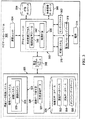
これより図3を参照すると、例示的な一実施形態によるナビゲーション・システムのブロック図が示されている。ナビゲーション・システム300は、図1におけるナビゲーション・システム112の一実施態様の一例である。
With reference now to FIG. 3, a block diagram of a navigation system is depicted in accordance with an illustrative embodiment. Navigation system 300 is an example of one implementation of
ナビゲーション・システム300は、プロセッサ・ユニット302、通信ユニット304、行動データベース306、作業現場データベース308、可動システム310、センサ・システム312、電源314、電力レベル・インディケータ316、基本システム・インターフェース318、および環境データ収集システム320を含む。環境データ収集システム320は、環境センサ・システム322、複数のデータベース324、および環境データ発生器326を含む。
The navigation system 300 includes a
環境センサ・システム322は、図1における複数の作業現場特徴106のような作業現場特徴、および図1における複数の作業現場のような作業現場におけるその他の環境データを検出する。他の環境データは、例えば、限定ではなく、風、降水量、温度、季節、および/または任意のその他の適した環境データを含むことができる。環境センサ・システム322は、視覚システム328を含む。視覚システム328は、例えば、限定ではなく、ステレオ視覚システム、非対称視覚システム、スタジアメトリック測距視覚システム(stadiametric ranging vision system)、および/または任意のその他の適した視覚システムとすることができる。視覚システム328は、複数のカメラ330を含む。複数のカメラ330は、例えば、図1における作業現場116のような、作業現場または作業現場エリアの画像を撮影するために用いることができる。複数のカメラ330によって撮影された画像は、例えば、ランドマーク識別および経路計画に用いるために、基本システム・インターフェース318を通じてプロセッサ・ユニット302に転送することができる。本明細書において用いる場合、「複数の」は1つ以上の画像に言及するものとする。複数のカメラ330は、例えば、限定ではなく、カラー・カメラ、白黒カメラ、赤外線カメラ、および/または任意のその他の適したカメラを含むことができる。
The
環境データ収集システム320の複数のデータベース324は、図1における作業現場環境100のような作業現場環境と関連のある園芸および天候情報を提供する。複数のデータベース324は、例えば、限定ではなく、園芸データベース332、天候データベース334、オンライン・データベース336、および/または任意のその他の適したデータベースを含むことができる。
The plurality of
園芸データベース332は、限定ではなく、植物種および変種のような情報、ならびに植物種および変種の給水の必要性、成長段階、特性、および成長過程についての情報、自律車両に影響を及ぼすかもしれない作業現場環境の具体的な環境的特徴等を含むことができる。例えば、種々の植物種の特性は、限定ではなく、幹、樹皮、分枝系統、幹のサイズ、葉のパターン、発芽、非発芽(non-budding)、色、成長パターン、好ましい日照、好ましい土壌水分、好ましい土壌pH等とすることができる。天候データベース334は、作業現場環境についての現在の天候、作業現場環境についての天候履歴等を含むことができる。
オンライン・データベース336は、通信ユニット304を用いてワイヤレスでインターネットにアクセスすることができる。オンライン・データベース336は、動的に情報を環境データ収集システム320に提供し、これによって、環境データ発生器326によって発生されたデータに対する調節が可能になる。例えば、オンライン・データベース336は、限定ではなく、作業現場環境の現在の天候状態、作業現場環境に対する現在の制約、作業現場環境についての天気予報、および/または任意のその他の適した情報を含むことができる。現在の制約には、限定ではなく、洪水のような、自律車両には望ましくない地面状態というような、複数の制約を含むことができる。
Online database 336 can access the Internet wirelessly using
例の中には、オンライン・データベース336がリモート・アクセス・データベースであるともよい場合もある。オンライン・データベース336によって提供されるこの天候情報は、作業現場環境について高い精度の環境データを取得するためには、環境センサ・システム322のどのセンサを活性化すべきか判定するために、環境データ収集システム320によって用いることができる。雨、雪、霧、および霜というような天候のために、ある種のセンサの範囲が狭くなったり、作業現場環境から高い精度の環境データを取得するためには他のセンサの属性の調節を行わなければならない場合もある。入手することができる他のタイプの情報には、限定ではなく、枝葉展開、落ち葉状態、芝水分応力(lawn moisture stress)というような植物の成長過程情報が含まれる。
In some examples, the online database 336 may be a remote access database. This weather information provided by online database 336 collects environmental data to determine which sensors of
環境データ発生器326は、複数のカメラ330によって撮影された画像、環境センサ・システム322によって検出されたその他の環境データ、および複数のデータベース324からの情報を用いて、図1における作業現場116のような、作業現場に関する作業現場データ327を発生する。作業現場データ327は、例えば、作業現場地図上における作業現場特徴の自動標識付けにおいて用いるために、図1における作業現場特徴識別システム103に送ることができる。
The
プロセッサ・ユニット302は、図2におけるデータ処理システム200の一実施態様の一例とすることができる。プロセッサ・ユニット302は、車両制御プロセス338を含む。車両制御プロセス338は、可動システム310と通信しこれを制御するように構成されている。車両制御プロセス338は、経路計画モジュール340を含む。経路計画モジュール340は、行動データベース306および作業現場データベース308からの情報を、環境データ収集システム320から受け取った作業現場データ327と共に用いて、経路計画342を作成することができる。経路は、任意の長さでよく、例えば、1フィートまたは10フィートでもよく、自律車両のランドマーク、障害物、周辺、および/または境界線に対する位置が変化するに連れて変化してもよい。
The
例示的な一例では、車両制御プロセス338は、図1における作業現場116のような作業現場全域について経路計画342を計画するために、作業現場データベース308から作業現場地図を引き出すことができる。車両制御プロセス338は、経路計画342を用いてコマンドおよび/または信号を可動システム310に送り、経路計画342にしたがって、ナビゲーション・システム300と関連のある自律車両を移動させることができる。車両制御プロセス338は、例えば、作業現場特徴識別において用いるために作業現場を調査し画像を取り込むために、経路計画342全域にわたって自律車両を移動させることができる。車両制御プロセス338は、例えば、限定ではなく、自立車両上で選択されるボタン、手動制御デバイスからのコマンド、ソフトウェア・ドリブン・イベント、時間ドリブン・イベント、および/または任意のその他の適したトリガというような、トリガに応答して、作業現場の調査を開始することができる。
In one illustrative example, the
また、プロセッサ・ユニット302は、行動データベース306および作業現場データベース308と通信しこの中に格納されているデータにアクセスすることができる。データにアクセスするには、行動データベース306および/または作業現場データベース308の中にデータを格納する、これらからデータを引き出す、および/またはこのデータに対して作用するための任意のプロセスを含むことができる。例えば、データにアクセスするには、限定ではなく、行動データベース306および/または作業現場データベース308に収容されている参照表を用いること、行動データベース306および/または作業現場データベース308を用いて照会プロセスを実行すること、および/またはデータベースに格納されているデータにアクセスするための任意のその他の適したプロセスを含むことができる。
The
プロセッサ・ユニット302は、センサ・システム312から情報を受け取り、可動システム310を制御するときに、センサ情報を、行動データベース306からの行動データと共に用いることができる。また、プロセッサ・ユニット302は、例えば、図1におけるユーザ108によって動作させられる手動制御デバイス110のような、外部コントローラからの制御信号を受け取ることもできる。これらの制御信号は、通信ユニット304を用いて、プロセッサ・ユニット302によって受け取ることができる。
The
通信ユニット304は、情報を受け取るための通信リンクをプロセッサ・ユニット302に設けることができる。この情報は、例えば、データ、コマンド、および/または命令を含む。通信ユニット304は、種々の形態をなすことができる。例えば、通信ユニット304は、セルラ・フォン・システム、Wi−Fiワイヤレス・システム、または何らかのその他の適したワイヤレス通信システムというような、ワイヤレス通信システムを含むことができる。
また、通信ユニット304は、例えば、図1における手動制御デバイス110のような、任意の(optional)手動コントローラへの有線接続も含むことができる。更に、通信ユニット304は、例えば、ユニバーサル・シリアル・バス・ポート、シリアル・インターフェース、パラレル・ポート・インターフェース、ネットワーク・インターフェース、または物理的な通信リンクを設けるための何らかのその他の適したポートというような、通信ポートも含むことができる。通信ユニット304は、例えば、外部制御デバイスまたはユーザと通信するために用いることができる。
The
例示的な一例では、プロセッサ・ユニット302は、図1においてユーザ108によって動作させられる手動制御デバイス110から制御信号を受け取ることができる。これらの制御信号は車両制御プロセス338の自律行動を無効にして、ユーザ108に、ナビゲーション・システム300と関連のある自律車両を停止、始動、操舵、および/またはそれ以外で制御させることができる。
In one illustrative example,
行動データベース306は、可動システム310を制御するときに車両制御プロセス338が利用することができる複数の行動行為(behavioral action)を収容する。行動データベース306は、限定ではなく、基本的な車両行動、エリア・カバレッジ行動、周囲行動、障害物回避行動、手動制御行動、給電行動、および/または自律車両のための任意のその他の適した行動を含むことができる。
The
可動システム310は、図1における自律車両104のような、自律車両に移動可能性(mobility)を備える。可動システム310は、種々の形態をなすことができる。可動システム310は、例えば、限定ではなく、推進システム、操舵システム、制動システム、および可動コンポーネントを含むことができる。これらの例では、可動システム310は、車両制御プロセス338からコマンドを受け取り、これらのコマンドに応答して、関連のある自律車両を移動させることができる。
The
センサ・システム312は、センサ・データを収集しプロセッサ・ユニット302に送信するための複数のセンサ・システムを含むことができる。例えば、センサ・システム312は、限定ではなく、推測航法システム、障害物検出システム、周辺検出システム、および/または図5に更に詳細に例示的に示すような、何らかのその他の適したタイプのセンサ・システムを含むことができる。センサ・データとは、センサ・システム312によって収集された情報のことである。
The
電源314は、ナビゲーション・システム300、および例えば、図1における自律車両104のような、関連のある自律車両のコンポーネントに電力を供給する。電源314は、限定ではなく、バッテリ、移動バッテリ再充電器、ウルトラキャパシタ(ultracapacitor)、燃料電池、ガス発電機(gas powered generator)、太陽電池、および/または任意のその他の適した電源を含むことができる。電力レベル・インディケータ316は、電源314のレベルを監視し、電源レベルをプロセッサ・ユニット302に伝達する。例示的な一例では、電力レベル・インディケータ316は、電源314における電力の低レベルについての情報を送ることができる。プロセッサ・ユニット302は、行動データベース306にアクセスして、この例示的な例では、低電力レベルの指示に応答して、行動行為を採用することができる。例えば、限定ではなく、行動行為は、低電力レベルの検出に応答して、タスクの処理を中止すること、および再充電ステーションを探すこととしてもよい。
The
基本システム・インターフェース318は、環境データ収集システム320とその他のコンポーネントとの間において給電およびデータ通信を行う。例示的な一例では、基本システム・インターフェース318を用いて、複数のカメラ330によって撮影した画像を環境データ収集システム320からプロセッサ・ユニット302に転送することができる。
The
図3におけるナビゲーション・システム300の図示は、異なる有利な実施形態を実現することができる態様に対して、物理的または構造的限定を暗示することを意味するのではない。図示したコンポーネントに加えておよび/またはこれらに代わって他のコンポーネントを用いることもできる。有利な実施形態によっては、一部のコンポーネントが不要な場合もある。または、ブロックは一部の機能的コンポーネントを例示するために示されている。異なる有利な実施形態において実現するときには、これらのブロックの1つ以上を組み合わせること、および/または異なるブロックに分割することもできる。 The illustration of navigation system 300 in FIG. 3 is not meant to imply physical or structural limitations to the manner in which different advantageous embodiments may be implemented. Other components may be used in addition to and / or instead of the components shown. Some components may not be necessary in some advantageous embodiments. Or, the blocks are shown to illustrate some functional components. When implemented in different advantageous embodiments, one or more of these blocks may be combined and / or divided into different blocks.
例えば、例示的な一実施形態では、環境センサ・システム332を、ナビゲーション・システム300のセンサ・システム312と統合することもできる。別の例示的な実施形態では、環境データ収集システム320をナビゲーション・システム300のプロセッサ・ユニット302と統合することもできる。
For example, in an exemplary embodiment,
更に別の例示的な実施形態では、視覚システム328は、環境センサ・システム332とは別個のコンポーネントであってもよく、例えば、基本システム・インターフェース318を用いて、プロセッサ・ユニット302および/または環境データ収集システム320と相互作用することもできる。更に別の例示的な例では、複数のデータベース324をナビゲーション・システム300から離れて配置し、通信システム304を用いて環境データ収集システム320がアクセスするようにしてもよい。
In yet another exemplary embodiment, the vision system 328 may be a separate component from the
図4は、例示的な一実施形態による可動システムのブロック図である。可動システム400は、図3における可動システム310の一実施態様の一例である。
可動システム400は、図3におけるナビゲーション・システム300のような、ナビゲーション・システムと関連のある自律車両に移動可能性を与える。可動システム400は、種々の形態をなすことができる。可動システム400は、例えば、限定ではなく、推進システム402、操舵システム404、制動システム406、および複数の可動コンポーネント408を含むことができる。これらの例では、推進システム402は、図3におけるナビゲーション・システム300のようなナビゲーション・システムからのコマンドに応答して、図1における自律車両104のような自律車両を推進させるまたは移動させることができる。
FIG. 4 is a block diagram of a mobile system according to an exemplary embodiment.
推進システム402は、ナビゲーション・システムのプロセッサ・ユニットから受け取った命令に応答して、自律車両が移動する速度を維持または上昇させることができる。推進システム402は、電気制御推進システムとすることができる。推進システム402は、例えば、限定ではなく、内燃エンジン、内燃エンジン/電気混成システム、電気エンジン(electric engine)、または何らかのその他の適した推進システムとすることができる。例示的な一例では、推進システム402は車輪駆動モータ410を含むことができる。車輪駆動モータ410は、車輪のような可動コンポーネントに組み込まれている電気モータとすることができ、可動コンポーネントを直接駆動する。例示的な一実施形態では、車輪駆動モータ410を差動的に制御することによって、操舵を行うこともできる。
The
操舵システム404は、ナビゲーション・システムのプロセッサ・ユニットから受け取ったコマンドに応答して、自律車両の方向または操舵を制御する。操舵システム404は、例えば、限定ではなく、電気制御油圧操舵システム、電気駆動ラックおよびピニオン操舵システム、差動操舵システム、または何らかのその他の適した操舵システムとすることができる。例示的な一例では、操舵システム404は、複数の可動コンポーネント408を制御するように構成された専用車輪を含むことができる。
制動システム406は、ナビゲーション・システムのプロセッサ・ユニットから受け取ったコマンドに応答して、自律車両を減速および/または停止させることができる。制動システム406は、電気制御制動システムとすることができる。この制動システムは、例えば、限定ではなく、油圧制動システム、摩擦制動システム、車輪駆動モータ410を用いた再生制動システム、または電気的に制御することができる何らかの他の適した制動システムとすることができる。例示的な一例では、ナビゲーション・システムは、図1における手動制御デバイス110のような外部コントローラからコマンドを受け取り、緊急停止装置を活性化させることができる。ナビゲーション・システムは、コマンドを可動システム400に送り、制動システム406を制御して、この例示的な例では、緊急停止を実行することができる。
The
複数の可動コンポーネント408は、ナビゲーション・システムのプロセッサ・ユニットから受け取り、推進システム402、操舵システム404、および制動システム406によって実行する命令に応答して、複数の方向および/または位置に移動する能力を、自律車両に設ける。複数の可動コンポーネント408は、例えば、限定ではなく、車輪、トラック(tracks)、フィート(feet)、ロータ、プロペラ、翼、および/またはその他の適したコンポーネントとすることができる。
The plurality of
図4における可動システム400の図示は、異なる有利な実施形態を実現することができる態様に対して、物理的または構造的限定を暗示することを意味するのではない。図示したコンポーネントに加えておよび/またはこれらに代わって他のコンポーネントを用いることもできる。有利な実施形態によっては、一部のコンポーネントが不要な場合もある。または、ブロックは一部の機能的コンポーネントを例示するために示されている。異なる有利な実施形態において実現するときには、これらのブロックの1つ以上を組み合わせること、および/または異なるブロックに分割することもできる。
The illustration of
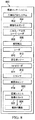
図5は、例示的な一実施形態によるセンサ・システムのブロック図である。センサ・システム500は、図3におけるセンサ・システム312の一実施態様の一例である。
センサ・システム500は、センサ・データを収集し、図3におけるナビゲーション・システム300のような、ナビゲーション・システムのプロセッサ・ユニットにセンサ・データを送信するために複数のセンサ・システムを含む。センサ・システム500は、障害物検出システム502、周辺検出システム504、および推測航法システム506を含む。
FIG. 5 is a block diagram of a sensor system in accordance with an exemplary embodiment.
The
障害物検出システム502は、限定ではなく、複数のコンタクト・スイッチ508および超音波変換器510を含むことができる。複数のコンタクト・スイッチ508は、例えば、図1における作業現場環境100のような環境における自律車両の外部物体との接触を検出する。複数のコンタクト・スイッチ508は、例えば、限定ではなく、バンパ・スイッチを含むことができる。超音波変換器510は、高周波音波を発生し、戻ってくるエコーを評価する。超音波変換器510は、信号、即ち、高周波音波を送ってからエコーを受信するまでの時間間隔を計算して、物体までの距離を決定する。
周辺検出システム504は、図1における作業現場116のような作業現場の周辺または境界線を検出し、周辺検出についての情報を、ナビゲーション・システムのプロセッサ・ユニットに送る。周辺検出システム504は、限定ではなく、受信機512および赤外線検出器514を含むことができる。受信機512は、例えば、図1における作業現場116のような、作業現場の周辺を規定するワイヤによって発することができる電気信号を検出する。赤外線検出器514は、例えば、図1における作業現場116のような、作業現場の周辺に沿って赤外線光源によって放出することができる赤外線光を検出する。
The
例示的な一例では、受信機512は、周辺ワイヤからの電気信号を検出し、その検出した信号についての情報を、図3におけるナビゲーション・システム300のような、ナビゲーション・システムのプロセッサ・ユニットに送ることができる。次いで、ナビゲーション・システムは、図4における可動システム400のような、可動システムにコマンドを送り、この例示的な例では、ナビゲーション・システムと関連のある自律車両の方向または行程を変更することができる。
In one illustrative example,
推測航法システム506は、ナビゲーション・システムと関連のある自律車両の現在地を推定する。推測航法システム506は、既に決定されている位置、ならびに経過時間および行程において、既知の速度または推定速度についての情報に基づいて、現在地を推定する。推測航法システム506は、限定ではなく、オドメータ516、コンパス518、および加速度計520を含むことができる。オドメータ516は、図1における自律車両104のような機械が走行した距離を示すために用いられる電子または機械的デバイスである。コンパス518は、地球の磁極に対する位置または方向を決定するために用いられるデバイスである。加速度計520は、自由落下に対してそれが受けた加速度を測定する。
図5におけるセンサ・システム500の図示は、異なる有利な実施形態を実現することができる態様に対して、物理的または構造的限定を暗示することを意味するのではない。図示したコンポーネントに加えておよび/またはこれらに代わって他のコンポーネントを用いることもできる。有利な実施形態によっては、一部のコンポーネントが不要な場合もある。または、ブロックは一部の機能的コンポーネントを例示するために示されている。異なる有利な実施形態において実現するときには、これらのブロックの1つ以上を組み合わせること、および/または異なるブロックに分割することもできる。
The illustration of
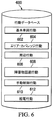
図6は、例示的な一実施形態による行動データベースのブロック図である。行動データベース600は、図3における行動データベース306の一実施態様の一例である。
行動データベース600は、図3における可動システム310を制御するときに、ナビゲーション・システム300の車両制御プロセス338が利用することができる複数の行動行為を含む。行動データベース600は、限定ではなく、基本的車両行動602、エリア・カバレッジ行動604、周辺行動606、障害物回避行動608、手動制御行動610、給電行動612、および/または自律車両のための任意のその他の適した行動を含むことができる。
FIG. 6 is a block diagram of a behavior database according to an exemplary embodiment. The
The
基本車両行動602は、自律車両が実行することができる複数の基本タスクについて行為を規定する。基本車両行動602は、限定ではなく、芝刈り、清掃(vacuuming)、床磨き、落ち葉掃除、除雪、散水、噴霧、セキュリティ、および/または任意のその他の適したタスクを含むことができる。
The
エリア・カバレッジ行動604は、基本車両行動602を実行するときにエリア・カバレッジについて行為を規定する。エリア・カバレッジ行動604は、限定ではなく、区域分解行動、り耕体(boustrouphadon)エリア・カバレッジ行動、螺旋形エリア・カバレッジ行動、カスタム化経路計画、および/または任意のその他の適したエリア・カバレッジ行動を含むことができる。区域分解行動は、例えば、限定ではなく、円弧追従(follow arc)行動、二点間行動、および/または任意のその他の適した行動を含むことができる。
The
周辺行動606は、図5における周辺検出システム504によるというような、周辺検出に応答したナビゲーション・システムについての行為を規定する。例示的な一例では、周辺行動606は、限定ではなく、周辺追従、進行方向変更、および/または任意のその他の適した行動を含むことができる。進行方向変更は、例えば、周辺の内部に留まるために、ある角度だけ自律車両の進行方向を変更するように動作することができる。周辺追従は、予め定められた距離だけ自律車両を周辺に平行に移動させるように動作することができる。予め定められた距離は、例えば、自律車両の幅から誤差量を減算した値に等しくすることができる。
障害物回避行動608は、ナビゲーション・システムが自律車両周囲の環境における物体との衝突を回避するための行為を規定する。例示的な一例では、障害物回避行動608は、限定ではなく、障害物周回、逆方向および進行方向変更、および/または任意のその他の適した行動を含むことができる。障害物周回は、例えば、障害物周囲にある全エリアにおいてタスクを実行するために、自律車両を障害物の回りで誘導して、元の経路に沿ってまたは障害物全体の周囲を進行するように動作することができる。逆方向および進行方向変更は、図5における障害物検出システム502のような障害物検出システムによって検出された物体を回避するために、前方に移動する前に自律車両の方向を逆転し、ある角度だけ進行方向を変更するように動作することができる。
The
手動制御行動610は、ナビゲーション・システムが、自律性をディスエーブルし、例えば、図1におけるユーザ108のようなユーザからの運動制御を採用するための行為を規定する。給電行為612は、ナビゲーション・システムが、図3における電源314のような電源において検出した電力レベルに応答して、複数の措置を講ずるための行為を規定する。例示的な一実施形態では、給電行動612は、限定ではなく、自律車両のタスク処理を停止し、自律車両のために追加電力または電力再充電を探し出すことを含むことができる。
図6における行動データベース600の図示は、異なる有利な実施形態を実現することができる態様に対して、物理的または構造的限定を暗示することを意味するのではない。図示したコンポーネントに加えておよび/またはこれらに代わって他のコンポーネントを用いることもできる。有利な実施形態によっては、一部のコンポーネントが不要な場合もある。または、ブロックは一部の機能的コンポーネントを例示するために示されている。異なる有利な実施形態において実現するときには、これらのブロックの1つ以上を組み合わせること、および/または異なるブロックに分割することもできる。
The illustration of the
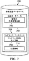
図7は、例示的な一実施形態による作業現場データベースのブロック図である。作業現場データベース700は、図3における作業現場データベース308の一実施態様の一例である。
FIG. 7 is a block diagram of a work site database according to an exemplary embodiment.
作業現場データベース700は、経路を計画するときおよび/または図3における可動システム310を制御するときに、ナビゲーション・システム300のプロセッサ・ユニット302が利用することができる複数のデータベースを含む。作業現場データベース700は、限定ではなく、地図データベース702、ランドマーク・データベース704、および/または自律車両についての情報の任意のその他の適したデータベースを含むことができる。
The
地図データベース702は、複数の作業現場地図706を含む。複数の作業現場地図706は、例えば、図1における複数の作業現場106に対応することができる。例示的な一実施形態では、複数の作業現場地図706は、ネットワーク101を用いて図1におけるバック・オフィス102のような遠隔地から地図データベース702にロードすることができる。別の例示的な実施形態では、複数の作業現場地図706は、図1において作業現場特徴識別システム103によって更新された後に、地図データベース702に格納することもできる。更に別の例示的な実施形態では、例えば、基本システム・インターフェース318を通じて図1のユーザ108のようなユーザ、および/または図3における通信ユニット304によって、複数の作業現場地図706を地図データベース702にロードすることもできる。
The
ランドマーク・データベース704は、ランドマーク画像および定義708、ならびに位置情報710を含むことができる。ランドマーク画像および定義708は、例えば、図1における作業現場116の中にある複数のランドマーク122のような作業現場の中にある複数のランドマークを識別することができる。位置情報710は、ランドマーク画像において識別された各ランドマーク、および作業現場内における位置に対する定義708を識別する。位置情報710は、例えば、地図データベース702に格納されている複数の作業現場地図706と関連付けることもできる。
The
例示的な一例では、ランドマーク・データベース704は、作業現場特徴識別システム103によって、図1における環境データ収集システム114によって検出された環境データを用いて、自動的に更新することができる。別の例示的な例では、ランドマーク・データベース704は、図1における環境データ収集システム114から作業現場特徴データを受け取った後に、図1におけるユーザ108のようなユーザによって更新することもできる。
In one illustrative example, the
図7における作業現場データベース700の図示は、異なる有利な実施形態を実現することができる態様に対して、物理的限定またはアーキテクチャの限定を暗示することを意味するのではない。図示したコンポーネントに加えておよび/またはこれらに代わって他のコンポーネントを用いることもできる。有利な実施形態によっては、一部のコンポーネントが不要な場合もある。または、ブロックは一部の機能的コンポーネントを例示するために示されている。異なる有利な実施形態において実現するときには、これらのブロックの1つ以上を組み合わせること、および/または異なるブロックに分割することもできる。
The illustration of the
これより図8を参照すると、例示的な一実施形態による作業現場地図のブロック図が示されている。作業現場地図800は、図3における環境データ収集システムの環境センサ・システム322の一実施態様の一例とすることができる。
With reference now to FIG. 8, a block diagram of a work site map is depicted in accordance with an illustrative embodiment.
図示のように、環境センサ・システム800は、例えば、限定ではなく、汎地球測位システム802、構造化光センサ804、二次元/三次元レーザ・レーダ806、推測航法システム808、レーダ810、超音波ソナー812、無線周波数識別リーダ(RFID)814、雨センサ816、周囲光センサ818、および視覚システム820を含むことができる。これらの異なるセンサは、図1における自律車両104のような、自律車両周囲の環境を識別するために用いることができる。例えば、これらのセンサsは、作業現場116における複数の作業現場特徴120というような、自律車両周囲の作業現場環境において作業現場特徴を検出するために用いることができる。別の例では、これらのセンサは、環境における動的状態を検出するために用いることができる。動的状態とは、例えば、限定ではなく、風速、風向、降雨量、温度、および/または作業現場環境における任意のその他の状態とすることができる。
As shown, the
汎地球測位システム802は、作業現場環境における他の物体に対する自律車両の位置を特定することができる。汎地球測位システム802は、信号強度および/または飛行時間に基づく、任意のタイプの無線周波数三角測量方式とすることができる。例には、限定ではなく、汎地球測位システム、Glonass、Galileo、およびセル・タワー相対信号強度が含まれる。位置は、通例、誤差を含む、緯度および経度として報告される。誤差は、電離層状態、衛星コンスタレーション、および植物による信号減衰というような要因に左右される。汎地球測位システム802によって検出された位置確認情報は、例えば、作業現場環境内にあるランドマークの位置(position)および局在性(localization)を特定するために用いることができる。 The global positioning system 802 can determine the position of the autonomous vehicle relative to other objects in the work site environment. The global positioning system 802 can be any type of radio frequency triangulation scheme based on signal strength and / or time of flight. Examples include, but are not limited to, Global Positioning System, Glonass, Galileo, and Cell Tower relative signal strength. The location is typically reported as latitude and longitude, including errors. The error depends on factors such as ionospheric conditions, satellite constellations, and signal attenuation by plants. The position confirmation information detected by the global positioning system 802 can be used, for example, to identify the position and localization of landmarks in the work site environment.
構造化光センサ804は、1本以上の線というようなパターンで光を放出し、カメラを通した光の反射を読み取り、この反射を解釈して、環境における物体を検出および測定する。二次元/三次元レーザ・レーダ806は、散乱光の特性を測定し、離れた目標の距離および/またはその他の情報を発見する光学遠隔検知技術である。二次元/三次元レーザ・レーダ806は、レーザ・パルスをビームとして放出し、次いでこのビームを走査して二次元または三次元距離行列(range matrix)を発生する。距離マトリクスは、パルスの送信と反射信号の検出との間の時間遅延を測定することによって、物体または表面までの距離を判定するために用いられる。
The structured
推測航法808は、既知の位置から開始し、既知の速度、経過時間、および経路に基づいて、次いで数学的にまたは直接その位置から前進する。この速度に基づく前進は、車両オドメータ、または地上速度レーダを用いて、既知の位置から走行した距離を決定することができる。レーダ810は、当技術分野では周知であり、物体までの距離を測定するために飛行時間モードで用いることができ、更に物体の速度を計算するためにドプラー・モードでも用いることができる。レーダ810は、電磁波を用いて、移動物体および固定物体双方の距離、高度、方向、または速度を特定する。超音波ソナー812は、超音波周波数における音の伝搬を用いて、パルスの送信から受信までの時間を測定し、既知の音速を用いてこの測定値を距離に変換することによって、物体までの距離を測定する。超音波ソナー812は、当技術分野では周知であり、レーダ810と同様に、飛行時間モードまたはドプラー・モードで用いることができる。無線周波数識別リーダ(RFID)814は、格納されているデータを拠り所とし、無線周波数識別(RFID)タグまたはトランスポンダと呼ばれるデバイスを用いてデータを引き出す。雨センサ816は、自動車両の外面上における降雨量を検出する。周囲光センサ818は、作業現場環境における周囲光の量を測定する。
視覚システム820は、例えば、限定ではなく、ステレオ視覚システム、非対称視覚システム、スタジアメトリック測距視覚システム(stadiametric ranging vision system)、および/または任意のその他の適した視覚システムとすることができる。視覚システム820は、複数のカメラ822を含む。複数のカメラ822は、例えば、赤外線カメラ、可視光カメラ、カラー・カメラ、白黒カメラ、ディジタル・カメラ、および/または任意のその他の適したカメラを含む、任意のタイプのカメラとすることができる。赤外線カメラは、無生物物体に対して生体を示す熱を検出する。また、赤外線カメラは、赤外線放射線を用いて画像を形成することもできる。可視光カメラは、標準的な静止画カメラとすればよく、色情報のために単体で用いたり、あるいは第2カメラと共にステレオ画像または三次元画像を発生するために用いることもできる。可視光カメラを第2カメラと共に用いてステレオ画像を発生する場合、2つ以上のカメラを異なる露出設定値に設定すると、ある範囲の照明条件において、性能向上を実現することができる。また、可視光カメラは、動画を撮影し記録するビデオ・カメラであってもよい。複数のカメラ822は、複数の画像824を撮影する。複数の画像824は、図3における環境データ収集システム320が作業現場についての環境データを発生するために用いることができる。また、複数の画像824は、図1における作業現場特徴識別システム103が、環境センサ・システム800によって作業現場において検出された作業現場の特徴を自動的に識別するためにも用いることができる。
The
環境センサ・システム800は、前述のセンサの1つ以上から環境データを引き出して、環境の異なる観点を得ることができる。例えば、環境センサ・システム800は、視覚システム820から視覚データを得ることができ、二次元/三次元レーザ・レーダ806から環境における物体に対する車両の距離についてのデータを得ることができ、更に汎地球測位システム802から地図に対する車両の位置データを得ることができる。
The
図8における環境センサ・システム800の図示は、異なる有利な実施形態を実現することができる態様に対して、物理的または構造的限定を暗示することを意味するのではない。図示したコンポーネントに加えておよび/またはこれらに代わって他のコンポーネントを用いることもできる。有利な実施形態によっては、一部のコンポーネントが不要な場合もある。または、ブロックは一部の機能的コンポーネントを例示するために示されている。異なる有利な実施形態において実現するときには、これらのブロックの1つ以上を組み合わせること、および/または異なるブロックに分割することもできる。
The illustration of
これより図9を参照すると、例示的な一実施形態による作業現場特徴識別システムのブロック図が示されている。作業現場特徴識別システム900は、図1における作業現場特徴識別システム103の一実施態様の例示的な一例である。
With reference now to FIG. 9, a block diagram of a work site feature identification system is depicted in accordance with an illustrative embodiment. Worksite
作業現場特徴識別システム900は、作業現場特徴データベース902、データ分類プロセス904、およびユーザ・インターフェース906を含む。作業現場特徴データベース902は、複数の候補物体908、物体プロパティ(property)910、複数の識別された物体912、複数の確認された物体914、複数の作業現場地図916、および複数の画像917を含む。複数の候補物体908は、位置的安定性を有する物体および/または、例えば、位置確認およびナビゲーションにおいて用いるためのランドマークとして適している物体のリストとすることができる。複数の候補物体908は、例えば、限定ではなく、コンクリート・スラブ、花壇、壁、壁柱、旗棒、樹木の幹、電柱、付属建築物、家、庭園構造、および/または位置的安定性のある任意のその他の適した物体を含むことができる。
Worksite
また、複数の候補物体908は、複数の物体908における候補物体の各々と関連のある物体属性907も含むことができる。物体属性907は、候補物体の特性についての情報であり、限定ではなく、色、表面模様、形状、寸法の比率、および/または任意のその他の適した特性等である。複数の候補物体908における各物体には、この例では、物体属性907における1つ以上の属性を関連付けることができる。物体属性907における色についての情報は、例えば、色相、彩度、ならびに値(HSV)色空間または色相、彩度、および明度(HSL)色空間というような、RGBカラー・モードにおいて点を表すための色空間を規定することができる。物体属性907における表面模様についての情報は、例えば、粗いから滑らかまでの表面模様の規模(scale)と関連付けられた数値で表すことができる。物体属性907における形状についての情報は、例えば、凸状、凹状、平坦、多面カット状(mutifaceted)、および/または任意のその他の適した形状基準というような基準を含むことができる。物体属性907における高さの比率についての情報は、例えば、高さ対幅の比率と関連付けられた数値で表すことができる。
The plurality of candidate objects 908 can also include object attributes 907 associated with each of the candidate objects in the plurality of
物体プロパティ910は、複数の候補物体908と関連のあるプロパティのリストを含む。物体プロパティ910は、例えば、限定ではなく、自律車両による走行可能性(traversability)、自律車両による非走行可能性、季節的変化、物質成分、および/または任意のその他の適した物体プロパティを含むことができる。物体プロパティ910は、例えば、図1における自律車両104にような自律車両の物理的行動に対して実世界効果を有する複数の候補物体908の属性である。例示的な一例では、複数の候補物体908は、自律車両による走行可能性の物体プロパティと関連のあるコンクリート・スラブを含むことができ、作業現場内において複数のタスクを実行している間にこのコンクリート・スラブを乗り越える際に、自律車両の物理的行動が生ずる。別の例示的な例では、複数の候補物体908は、自律車両による非走行可能性の物体プロパティと関連のある花壇を含むことができ、作業現場において複数のタスクを実行している間にこの花壇を避けるおよび/または迂回する自律車両の物理的行動が生ずる。更に別の例示的な例では、物体プロパティ910は、自律車両の動作命令と関連付けることもできる。この例では、複数の候補物体908は、非走行可能性の物体プロパティおよび「ぶつかるな」という動作命令と関連のある樹木を含むことができる。
また、作業現場地図において識別された作業現場特徴と関連のある物体プロパティ910は、ナビゲーション・システム300のようなナビゲーション・システムが、作業現場内において自律車両行動および経路計画を計画する際に用いることもできる。自律車両の実世界行動は、作業現場環境において識別された複数の候補物体908と関連のある物体プロパティ910による影響を受ける。
Also,
複数の識別された物体912は、物体識別と関連のある物体プロパティ、記述、および画像を含むことができる。複数の識別された物体912は、データ分類プロセス904によって自動的に識別された作業現場の特徴を表す。例示的な一例では、複数の識別された物体912は、色が茶色で表面模様が粗いという物体属性、および非走行可能性という物体プロパティを有する、円筒形で、狭い、垂直構造の物体を含むことができる。この例では、この物体は、データ分類プロセス904によって「樹木の幹」と識別することができる。
The plurality of identified
複数の確認された物体914は、例えば、図1におけるユーザ108のようなユーザによって既に確認されている物体識別と関連のある物体プロパティ、記述、および/または画像を含むことができる。例示的な一例では、データ分類プロセス904は、色が茶色で表面模様が粗いという物体属性、および非走行可能性という物体プロパティを有する、円筒形で、狭い、垂直構造の画像を、自動的に「樹木の幹」と識別することができる。ユーザは、ユーザ入力918をユーザ・インターフェース906を通じて供給して、この自動識別を確認することができ、データ分類プロセス904は、確認された物体識別およびプロパティを、複数の確認された物体914に格納することができる。また、複数の確認された物体914は、例えば、物体の直径または大きさというような、ユーザ入力918を通じてユーザによって追加された追加情報も含むことができる。この追加情報は、データ分類プロセス904が、例えば、倍率調整した作業現場地図を作成するために用いることができる。
The plurality of confirmed
複数の作業現場地図916は、データ分類プロセス904によって作成され、例えば、図3におけるナビゲーション・システム300のような自律車両のナビゲーション・システムによる経路計画において用いるために、作業現場特徴データベース902に格納される。
A plurality of
複数の画像917は、予め発生されている作業現場の画像データ、格納されている作業現場の画像、バック・オフィスからユーザにダウンロードされた作業現場の画像、および/または任意のその他の適した画像とすることができる。複数の画像917は、例示的な一例では、画像分析プロセス922が画像データ924を分析し、作業現場の特徴を識別するために用いることができる。
The plurality of
データ分類プロセス904は、画像分析プロセス922を含む。データ分類プロセス904は、画像データ924および/または環境データ926を、図3における環境データ収集システム320から受け取ることができる。画像データ924は、例えば、図3における視覚システム328から直接送信された複数の画像とすることができる。環境データ926は、例えば、図3における環境データ発生器326によって発生された、作業現場環境についての画像および関連する環境データを含むことができる。
画像分析プロセス922は、画像データ924および/または環境データ926を分析し、作業現場特徴データベース902を用いて、複数の物体識別928を発生する。また、画像分析プロセス922は、画像データ924および/または環境データ926を、作業現場特徴データベース902における複数の画像917と比較して、複数の画像917のうち少なくとも2つの画像間における共通の特徴を識別することができる。
データ分類プロセス904は、画像シーケンサ930を含む。画像シーケンサ930は、画像データ924および/または環境データ926から受け取った作業現場の複数の画像を分析して、編集画像931を発生する。編集画像931は、画像において撮影された物体の点群による、作業現場の複数の画像の三次元モデルである。画像シーケンサ930は、当技術分野では周知であるパターン認識アルゴリズムを用いて、画像の部分同士を比較して、点を作成する。次いで、画像シーケンサ930は、これらの点を比較して、画像をモデルに変換する。画像シーケンサ930は、複数の三次元モデル932を編集画像931から抽出する。複数の三次元モデル932は、画像における複数の物体の三次元モデルである。例示的な一例では、画像シーケンサ930は、樹木のような、中心的物体の三次元モデルを編集画像931から抽出することができる。
画像分析プロセス922は、複数の三次元モデル932の物体属性934を識別する。物体属性934とは、例えば、限定ではなく、色、表面模様、形状、寸法の比率、および/または任意のその他の適した特性というような、物体の物理的特性である。画像分析プロセス922は、複数の候補物体908における情報を用いて、候補物体と関連のある物体属性907のような複数の物体識別928を発生する。画像分析プロセス922は、複数の候補物体908を詳しく考察し、複数の三次元モデル932について識別された物体属性934を用いて、一致の確度に基づいて候補物体を選択することができる。
例示的な一例では、複数の三次元モデル932が、狭い、垂直、円筒形、茶色、および粗い表面模様の物体属性934を有する場合、画像分析プロセス922は、複数の候補物体908のうち、複数の候補物体908における物体の選択から、共有する属性を最も多く有する候補物体を特定することができる。この例示的な例では、候補物体である柱936には、狭い、垂直、円筒形、および茶色の物体属性907を関連付けることができ、一方候補物体である樹木の幹938には、狭い、垂直、円筒形、茶色、および粗い表面模様の物体属性907を関連付けることができる。この例示的な例では、候補物体である樹木の幹938が、物体属性934および物体属性907間において、最も多い数の共有属性を有し、一致の最大確度に基づいて、画像分析プロセス922によって物体識別として選択される。
In one illustrative example, if
画像データ924は、画像における作業現場の特徴と関連のあるスケーリング情報940を含むことができる。例示的な一例では、スケーリング情報940は、例えば、画像が自律車両の視覚システムによって撮影された時点における、自律車両に対する物体についての情報とすることができる。別の例示的な例では、スケーリング情報940は、例えば、カメラが人間によって操作される場合における、画像撮影時におけるカメラの位置に対する物体についての情報とすることができる。スケーリング情報940は、画像における物体の倍率(scale)またはサイズを決定するために用いられる。例えば、スケーリング情報940は、画像を撮影したときの自律車両の位置についての情報、自律車両の視覚システムの複数のカメラの有利な地点(vantage point)、自律車両のレーザ・レーダ・センサの走査角度、物体の自律車両からの距離、および/または任意のその他の適した情報を含むことができる。樹木の幹の例示的な例では、画像分析プロセス922によって、スケーリング情報940を用いて、この樹木の幹の直径を計算すると、例えば、外形形状を求めることができる。
The
データ分類プロセス904は、作業現場特徴データベース902に格納される複数の作業現場地図916を作成する。複数の作業現場地図916は、標識が付けられた作業現場地図であり、作業現場において自律車両の実世界、物理的動作に影響を及ぼす物体プロパティと関連のある、複数の識別された物体を有する。複数の作業現場地図916は、例えば、ナビゲーション・システム300のようなナビゲーション・システムによる位置確認および経路計画に用いられる。
The
オプションとして、データ分類プロセス904は、例えば、画像または環境データにおける作業現場の特徴の自動識別の確認のために、ユーザ・インターフェース906を通じて複数の物体識別928をユーザに送ることができる。ユーザは、自動識別を確認すること、および/または追加のプロパティまたは動作命令を識別することができる。確認された識別は、例えば、複数の確認された物体914に格納することができる。
Optionally, the
図9における作業現場特徴識別システム900の図示は、異なる有利な実施形態を実現することができる態様に対して、物理的または構造的限定を暗示することを意味するのではない。図示したコンポーネントに加えておよび/またはこれらに代わって他のコンポーネントを用いることもできる。有利な実施形態によっては、一部のコンポーネントが不要な場合もある。または、ブロックは一部の機能的コンポーネントを例示するために示されている。異なる有利な実施形態において実現するときには、これらのブロックの1つ以上を組み合わせること、および/または異なるブロックに分割することもできる。
The illustration of the shop floor
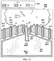
これより図10を参照すると、例示的な実施形態による画像のブロック図が示されている。画像1000は、図8における複数の画像824および/または図9における編集画像931の一実施態様の例示的な一例である。
Referring now to FIG. 10, a block diagram of an image according to an exemplary embodiment is shown.
例示的な一例では、画像1000は、図9における画像シーケンサ930のような画像シーケンサによって、例えば、図3における視覚システム328のような視覚システムによって撮影された複数の画像を用いて編集することができる。画像シーケンサ930は、図9における複数の三次元モデル932のような三次元モデルを画像1000から抽出することができる。この例示的な例では、画像1000の中心的物体は物体A1002である。物体A1002は、図9におけるユーザ・インターフェース906を用いて確認のために表示されたときに、画像シーケンサ930によって抽出し、画像1000上において赤で輪郭を示すことができる。画像分析プロセス922は、物体A1002について物体属性を識別する。この例では、物体A1002についての物体属性は、狭い、垂直、円筒状、茶色、および粗い表面模様であると言うことができる。キー1001は、抽出された三次元特徴の輪郭を示すために用いられた色の識別を行う。
In one illustrative example, the
画像分析プロセス922は、物体A1002を画像1000における樹木1004として識別する、または標識を付ける。この識別は、図9における作業現場特徴データベース902のような作業現場データベースを用いて判定することができる。例えば、画像分析プロセス922は、複数の候補物体908を詳しく考察して、候補物体と物体A1002との間において最も近い特性の一致を特定することができる。物体A1002が樹木1004として識別された場合、樹木と関連のある物体プロパティが、物体A1002と関連付けられる。画像分析プロセス922は、例えば、複数の物体プロパティまたは作業特徴データベース902において、関連のあるプロパティを識別することができる。樹木と関連のある物体プロパティは、例えば、非走行可能性、または「ぶつかるな」という動作命令とすることができる。
画像シーケンサ930は、例えば、図9におけるユーザ・インターフェース906を用いて確認のために画像1000が表示されたときに、画像1000において物体B1006を抽出し、黄色で物体B1006の輪郭を示すことができる。画像分析プロセス922は、図9における作業現場特徴データベース902を用いて、物体B1006を草地1008として識別する、または標識を付ける。草地1008には、例えば、走行可能性のような物体プロパティを関連付けることができる。この例示的な例では、草地1008という標識が付けられ走行可能性のプロパティと関連付けられた物体B1006は、例えば、作業現場内でタスクを実行するときに、自律車両が草地1008を横断することを規定することによって、この作業現場における自律車両の物理的動作に影響を及ぼす。
For example, when the
画像シーケンサ930は、例えば、図9におけるユーザ・インターフェース906を用いて確認のために画像1000が表示されたときに、画像1000において物体C1010を抽出し、白で物体C1010の輪郭を示すことができる。また、画像シーケンサ930は、画像において同様の三次元特性を有する複数のその他の物体も識別し、白でこれら複数の他の物体の輪郭を示すこともできる。画像分析プロセス922は、物体Cを壁柱であると識別し、この識別を、同じ特性を有し抽出された複数の他の物体に伝え、例えば、壁柱1012の標識を付けることができる。
For example, when the
図10における画像1000の図示は、異なる有利な実施形態を実現することができる態様に対して、物理的または構造的限定を暗示することを意味するのではない。図示したコンポーネントに加えておよび/またはこれらに代わって他のコンポーネントを用いることもできる。有利な実施形態によっては、一部のコンポーネントが不要な場合もある。または、ブロックは一部の機能的コンポーネントを例示するために示されている。異なる有利な実施形態において実現するときには、これらのブロックの1つ以上を組み合わせること、および/または異なるブロックに分割することもできる。
The illustration of
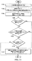
これより図11を参照すると、例示的な実施形態にしたがって画像においてランドマークを識別するプロセスのフローチャートが示されている。図11におけるプロセスは、例えば、図1における作業現場特徴識別システム103のようなコンポーネントによって実現することができる。
With reference now to FIG. 11, a flowchart of a process for identifying landmarks in an image is depicted in accordance with an illustrative embodiment. The process in FIG. 11 may be implemented by a component such as the work site
このプロセスが開始すると、作業現場の画像を受け取る(ステップ1102)。画像は、例えば、図1における環境データ収集システム114のような環境データ収集システムによって撮影することができる。この画像は、作業現場の中にあるランドマーク、物体、およびその他の特徴というような、複数の作業現場の特徴を含むことができる。
When this process begins, an image of the work site is received (step 1102). The image can be taken by an environmental data collection system, such as the environmental
本プロセスは、この画像を分析して、画像において示唆された物体の識別を判定する(ステップ1104)。本プロセスは、例えば、図9におけるデータ分類プロセス904のようなデータ分類プロセスの画像分析プロセスを用いて、画像を分析することができる。次いで、本プロセスは、物体の示唆された識別を通信ユニットを通じて送る(ステップ1106)。示唆された識別は、例えば、図9におけるユーザ・インターフェース906のようなユーザ・インターフェースを通じてユーザに送ることができる。ユーザは、この示唆された識別を受け取り、例えば、図9におけるユーザ入力918を通じて、この示唆された識別を確認または変更することができる。
The process analyzes this image to determine the identity of the object suggested in the image (step 1104). The process can analyze the image using, for example, an image analysis process of a data classification process, such as
次に、本プロセスは、示唆された識別が確認されたか否か判定する(ステップ1108)。示唆された識別が確認されたと判定された場合、本プロセスは、確認された識別を、確認された識別と関連のある複数の属性と共にデータベースに格納し(ステップ1110)、本プロセスはその後終了する。 Next, the process determines whether the suggested identification has been confirmed (step 1108). If it is determined that the suggested identity has been confirmed, the process stores the confirmed identity in a database with a plurality of attributes associated with the confirmed identity (step 1110), and the process then ends. .
示唆された識別が確認されていないと判定された場合、本プロセスは、示唆された識別の代わりに、既存の識別クラスが選択されたか否か判定する(ステップ1112)。既存の識別クラスとは、図9における作業現場特徴識別システム900のような作業現場特徴識別システム内において格納されているオブジェクト識別および/または以前作成された任意のオブジェクト識別とすることができる。識別クラスとは、例えば、図9における複数の候補物体908のような、任意の物体識別を指すことができる。
If it is determined that the suggested identity has not been confirmed, the process determines whether an existing identity class has been selected instead of the suggested identity (step 1112). An existing identification class may be an object identification stored in a worksite feature identification system, such as the worksite
既存の識別クラスが選択されていると判定された場合、本プロセスはステップ1110に進み、その後本プロセスは終了する。既存の識別クラスが選択されていないと判定された場合、本プロセスは、新たな識別クラスが作成されたか否か判定する(ステップ1114)。新たな識別クラスとは、図9における作業現場特徴識別システム900のような作業現場特徴識別システム内にあり、現在格納および/または認識されていない任意の物体識別とすることができる。新たな識別クラスは、例えば、図9における複数の候補物体908のように、作成すること、および/またはデータベースに格納することができる。
If it is determined that an existing identification class has been selected, the process proceeds to step 1110 and then the process ends. If it is determined that no existing identification class has been selected, the process determines whether a new identification class has been created (step 1114). The new identification class may be any object identification that is in a work site feature identification system, such as the work site
新たな識別クラスが作成されていないと判定された場合、本プロセスは終了する。新たな識別クラスが作成されていると判定された場合、本プロセスはステップ1110に進み、その後本プロセスは終了する。 If it is determined that a new identification class has not been created, the process ends. If it is determined that a new identification class has been created, the process proceeds to step 1110 and then the process ends.
本プロセスは、図9における複数の確認された物体914のように、確認された識別をデータベースに格納することができる。確認された識別は、例えば、作業現場地図において作業現場のランドマークを識別するために用いることができる。
The process can store confirmed identifications in a database, such as multiple confirmed
これより図12を参照すると、例示的な実施形態にしたがって作業現場の特徴を識別するプロセスを図示するフローチャートが示されている。図12におけるプロセスは、例えば、図1における作業現場特徴識別システム103のようなコンポーネントによって実現することができる。
Referring now to FIG. 12, a flowchart illustrating a process for identifying shop floor features is shown in accordance with an illustrative embodiment. The process in FIG. 12 can be implemented, for example, by a component such as the work site
本プロセスが開始すると、複数の作業現場画像を入手する(ステップ1202)。これら複数の作業現場画像は、例えば、図3における視覚システム328のような視覚システムを用いて入手することができる。図9における画像シーケンサ930のような画像シーケンサが、複数の作業現場画像を、例えば、作業現場の編集画像または三次元モデルに編集することができる。本プロセスは、複数の作業現場画像のうち少なくとも2つにおいて共通の特徴を識別する(ステップ1204)。この共通の特徴は、例えば、複数の作業現場画像から発生した作業現場の三次元モデルから抽出した三次元物体とすることができる。
When the process starts, a plurality of work site images are obtained (step 1202). These multiple work site images can be obtained using, for example, a visual system, such as visual system 328 in FIG. An image sequencer, such as the
次に、本プロセスは、少なくとも2つの画像において識別された共通の特徴の相対的位置を特定する(ステップ1206)。相対的位置とは、例えば、作業現場に対する位置とすればよい。相対的位置を決定するには、例えば、立体写真分析のような、複数の作業現場画像の分析に基づくことができる。別の例示的な例では、共通の特徴の相対的位置は、複数の作業現場画像の編集、および複数の作業現場画像から発生した三次元モデルにおける共通の特徴の位置に基づくことができる。 Next, the process identifies the relative positions of the common features identified in the at least two images (step 1206). The relative position may be a position with respect to the work site, for example. Determining the relative position can be based on the analysis of multiple shop floor images, such as, for example, stereographic analysis. In another illustrative example, the relative position of the common feature may be based on the editing of multiple work site images and the position of the common feature in a 3D model generated from the multiple work site images.
次に、本プロセスは、複数の作業現場画像において、1つでも共通の特徴が未だ残っているか否か判定する(ステップ1208)。複数の作業現場画像において共通の特徴が残っていると判定された場合、プロセスはステップ1204に戻る。複数の作業現場画像において共通の特徴が残っていないと判定された場合、本プロセスは、スケーリング情報が入手可能であるか否か判定する(ステップ1210)。 Next, the process determines whether at least one common feature still remains in the plurality of work site images (step 1208). If it is determined that common features remain in the plurality of work site images, the process returns to step 1204. If it is determined that no common features remain in the plurality of work site images, the process determines whether scaling information is available (step 1210).
スケーリング情報が入手可能でないと判定された場合、本プロセスは終了する。スケーリング情報が入手可能であると判定された場合、本プロセスは、このスケーリング情報を作業現場地図に適用して、作業現場についての距離情報を提供し、さらに識別された共通の特徴の大きさを示し(ステップ1212)、その後本プロセスは終了する。 If it is determined that scaling information is not available, the process ends. If it is determined that scaling information is available, the process applies this scaling information to the work site map to provide distance information about the work site and further determines the size of the identified common features. If indicated (step 1212), then the process ends.
異なる有利な実施形態の記載は、例示および説明を目的として提示したのであって、網羅的であることも、実施形態を開示した形態に限定することを意図するのではない。多くの変更および変容も当業者には明白であろう。更に、異なる実施形態は、他の実施形態と比較して、異なる利点を提供することができる。選択された1つまたは複数の実施形態は、本発明の原理、実用的用途を最良に説明するため、そして当業者が、想定される個々の使用に適するような種々の変更を加えた種々の実施形態について、本発明を理解することが可能となるために、選定し説明したのである。 The description of the different advantageous embodiments has been presented for purposes of illustration and description, and is not intended to be exhaustive or limited to the embodiments disclosed. Many modifications and variations will be apparent to practitioners skilled in this art. Furthermore, different embodiments may provide different advantages compared to other embodiments. The selected embodiment (s) are intended to best illustrate the principles, practical applications of the invention, and various modifications to which those skilled in the art may make various modifications suitable for the particular use envisioned. The embodiments have been selected and described in order to be able to understand the present invention.
Claims (17)
作業現場の画像を受け取るステップと、
前記画像において作業現場の特徴の示唆された識別を判定するために、前記画像を分析するステップと、
前記作業現場の特徴の前記示唆された識別を通信ユニットを通じて送るステップと、
確認された識別を形成するために、前記作業現場の特徴の前記示唆された識別の確認を受けるステップと、
前記確認された識別および前記作業現場の特徴と関連のある位置をデータベースに格納するステップと、
を含む、方法。 A method for identifying landmarks in an image, comprising:
Receiving an image of the work site;
Analyzing the image to determine a suggested identification of a site feature in the image;
Sending the suggested identification of the work site characteristic through a communication unit;
Receiving confirmation of the suggested identification of the site features to form a confirmed identification;
Storing the confirmed identification and location associated with the work site features in a database;
Including a method.
前記確認された識別および前記作業現場の特徴の複数の属性を、作業現場地図上における前記位置と関連付けるステップを含む、方法。 The method of claim 1, further comprising:
Associating a plurality of attributes of the confirmed identification and the work site features with the location on a work site map.
複数の作業現場画像を入手するステップと、
前記複数の作業現場画像のうち少なくとも2つにおいて共通の特徴を識別するステップと、
前記複数の作業現場画像のうち前記少なくとも2つにおいて識別した前記共通の特徴の相対的位置を特定するステップと、
を含む、方法。 The method of claim 1, further comprising analyzing the image to determine a suggested identification of a workplace feature in the image.
Obtaining a plurality of shop floor images;
Identifying common features in at least two of the plurality of work site images;
Identifying a relative position of the common feature identified in the at least two of the plurality of work site images;
Including a method.
前記識別された共通の特徴についてスケーリング情報が入手可能か否か判定するステップと、
スケーリング情報が入手可能であるという判定に応答して、前記作業現場における距離情報および前記共通の特徴の大きさを与えるために、前記スケーリング情報を適用するステップと、
を含む、方法。 The method of claim 6, further comprising:
Determining whether scaling information is available for the identified common features;
Applying the scaling information to provide distance information at the work site and the size of the common feature in response to a determination that scaling information is available;
Including a method.
作業現場特徴データベースと、
ユーザ・インターフェースと、
画像を分析するデータ分類プロセスを実行し、前記作業現場特徴データベースを用いて前記画像において作業現場の示唆された特徴の識別を判定し、前記作業現場の特徴の前記示唆された識別を通信ユニットを通じて送り、確認された識別を形成するために、前記作業現場の特徴の前記示唆された識別の確認を受け、前記確認された識別および該確認された識別と関連のある複数の属性を前記作業現場特徴データベースに格納するように構成されたデータ処理システムと、
を含む、システム。 A system for identifying landmarks in an image,
Work site feature database,
A user interface;
Performing a data classification process to analyze the image, determining an identification of the suggested feature of the work site in the image using the work site feature database, and determining the suggested identification of the work site feature through a communication unit Sending and confirming the suggested identification of the work site features to form a confirmed identification, and to identify the confirmed identification and a plurality of attributes associated with the confirmed identification A data processing system configured to be stored in a feature database;
Including the system.
前記確認された識別および前記作業現場の特徴の複数の属性を、作業現場地図上における位置と関連付けるために、前記データ分類プロセスを実行するように構成された、システム。 The system of claim 8, wherein the data processing system further comprises:
A system configured to perform the data classification process to associate a plurality of attributes of the identified identification and the work site feature with a location on a work site map.
複数の作業現場画像を入手するステップと、
前記複数の作業現場画像のうち少なくとも2つにおいて共通の特徴を識別するステップと、
前記識別された共通の特徴の相対的位置を特定するステップと、
前記作業現場の距離情報および識別された前記共通の特徴の大きさを与えるために、スケーリング情報を作業現場地図に適用するステップと、
を含む、方法。 A method for identifying features of a work site,
Obtaining a plurality of shop floor images;
Identifying common features in at least two of the plurality of work site images;
Identifying the relative position of the identified common features;
Applying scaling information to a work site map to provide distance information of the work site and the size of the identified common features;
Including a method.
前記複数の作業現場画像においていずれかの共通の特徴が未だ残っているか否か判定するステップと、
共通の特徴が残っているという判定に応答して、前記複数の作業現場画像のうち少なくとも2つにおいて次の共通の特徴を識別するステップと、
を含む、方法。 14. The method of claim 13, further comprising:
Determining whether any common features still remain in the plurality of work site images;
In response to determining that a common feature remains, identifying a next common feature in at least two of the plurality of shop floor images;
Including a method.
Applications Claiming Priority (2)
| Application Number | Priority Date | Filing Date | Title |
|---|---|---|---|
| US12/640,898 | 2009-12-17 | ||
| US12/640,898 US8340438B2 (en) | 2009-12-17 | 2009-12-17 | Automated tagging for landmark identification |
Publications (1)
| Publication Number | Publication Date |
|---|---|
| JP2011129126A true JP2011129126A (en) | 2011-06-30 |
Family
ID=43646500
Family Applications (1)
| Application Number | Title | Priority Date | Filing Date |
|---|---|---|---|
| JP2010281227A Pending JP2011129126A (en) | 2009-12-17 | 2010-12-17 | Automatic tagging for landmark identification |
Country Status (4)
| Country | Link |
|---|---|
| US (1) | US8340438B2 (en) |
| EP (1) | EP2336719A3 (en) |
| JP (1) | JP2011129126A (en) |
| AU (1) | AU2010252727A1 (en) |
Cited By (6)
| Publication number | Priority date | Publication date | Assignee | Title |
|---|---|---|---|---|
| JP2016063769A (en) * | 2014-09-24 | 2016-04-28 | 株式会社クボタ | Automatic travel vehicle |
| JP2018512687A (en) * | 2015-03-03 | 2018-05-17 | プレナヴ インコーポレイテッド | Environmental scanning and unmanned aircraft tracking |
| WO2019093316A1 (en) * | 2017-11-07 | 2019-05-16 | 国立研究開発法人宇宙航空研究開発機構 | Moving body positioning device, and calibration method therefor |
| JP2019534486A (en) * | 2017-04-21 | 2019-11-28 | エックス デベロップメント エルエルシー | Position measurement using negative mapping |
| JP2020126663A (en) * | 2016-02-15 | 2020-08-20 | 株式会社トプコン | Flight plan creation method and flying body guidance system |
| US20200326715A1 (en) * | 2017-11-13 | 2020-10-15 | Raven Industries, Inc. | Safety system for autonomous operation of off-road and agricultural vehicles using machine learning for detection and identification of obstacles |
Families Citing this family (147)
| Publication number | Priority date | Publication date | Assignee | Title |
|---|---|---|---|---|
| US8508590B2 (en) * | 2010-03-02 | 2013-08-13 | Crown Equipment Limited | Method and apparatus for simulating a physical environment to facilitate vehicle operation and task completion |
| US8538577B2 (en) * | 2010-03-05 | 2013-09-17 | Crown Equipment Limited | Method and apparatus for sensing object load engagement, transportation and disengagement by automated vehicles |
| US9014848B2 (en) * | 2010-05-20 | 2015-04-21 | Irobot Corporation | Mobile robot system |
| US8509982B2 (en) | 2010-10-05 | 2013-08-13 | Google Inc. | Zone driving |
| JP5832553B2 (en) | 2010-12-30 | 2015-12-16 | アイロボット コーポレイション | Coverage robot navigation |
| US9146559B2 (en) * | 2011-03-18 | 2015-09-29 | The Raymond Corporation | System and method for gathering video data related to operation of an autonomous industrial vehicle |
| AU2012243484B2 (en) | 2011-04-11 | 2014-10-30 | Crown Equipment Corporation | Method and apparatus for efficient scheduling for multiple automated non-holonomic vehicles using a coordinated path planner |
| US8655588B2 (en) | 2011-05-26 | 2014-02-18 | Crown Equipment Limited | Method and apparatus for providing accurate localization for an industrial vehicle |
| US8548671B2 (en) | 2011-06-06 | 2013-10-01 | Crown Equipment Limited | Method and apparatus for automatically calibrating vehicle parameters |
| US8594923B2 (en) | 2011-06-14 | 2013-11-26 | Crown Equipment Limited | Method and apparatus for sharing map data associated with automated industrial vehicles |
| US8589012B2 (en) | 2011-06-14 | 2013-11-19 | Crown Equipment Limited | Method and apparatus for facilitating map data processing for industrial vehicle navigation |
| US9689990B2 (en) * | 2011-08-05 | 2017-06-27 | Trimble Inc. | Dual coaxial NSS receiver system |
| US9671503B2 (en) * | 2011-08-06 | 2017-06-06 | Trimble Inc. | Mobile platform for conveying an NSS device |
| US20140058634A1 (en) | 2012-08-24 | 2014-02-27 | Crown Equipment Limited | Method and apparatus for using unique landmarks to locate industrial vehicles at start-up |
| US9056754B2 (en) | 2011-09-07 | 2015-06-16 | Crown Equipment Limited | Method and apparatus for using pre-positioned objects to localize an industrial vehicle |
| GB2495699B (en) | 2011-10-07 | 2019-03-27 | Samsung Electronics Co Ltd | Multimedia location-based sharing & multi-dimensional visualization |
| JP5858754B2 (en) * | 2011-11-29 | 2016-02-10 | キヤノン株式会社 | Imaging apparatus, display method, and program |
| US10846497B2 (en) | 2011-12-05 | 2020-11-24 | Adasa Inc. | Holonomic RFID reader |
| US11093722B2 (en) | 2011-12-05 | 2021-08-17 | Adasa Inc. | Holonomic RFID reader |
| KR101703177B1 (en) * | 2011-12-14 | 2017-02-07 | 한국전자통신연구원 | Apparatus and method for recognizing position of vehicle |
| US9949431B2 (en) * | 2011-12-28 | 2018-04-24 | Husqvarna Ab | Yard maintenance vehicle obstacle avoidance/notification system |
| US8668136B2 (en) | 2012-03-01 | 2014-03-11 | Trimble Navigation Limited | Method and system for RFID-assisted imaging |
| US8718861B1 (en) | 2012-04-11 | 2014-05-06 | Google Inc. | Determining when to drive autonomously |
| US9195914B2 (en) | 2012-09-05 | 2015-11-24 | Google Inc. | Construction zone sign detection |
| US9056395B1 (en) * | 2012-09-05 | 2015-06-16 | Google Inc. | Construction zone sign detection using light detection and ranging |
| US8996228B1 (en) * | 2012-09-05 | 2015-03-31 | Google Inc. | Construction zone object detection using light detection and ranging |
| US9633564B2 (en) | 2012-09-27 | 2017-04-25 | Google Inc. | Determining changes in a driving environment based on vehicle behavior |
| US8949016B1 (en) | 2012-09-28 | 2015-02-03 | Google Inc. | Systems and methods for determining whether a driving environment has changed |
| US8798926B2 (en) * | 2012-11-14 | 2014-08-05 | Navteq B.V. | Automatic image capture |
| US9820433B2 (en) | 2012-12-28 | 2017-11-21 | Positec Power Tools (Suzhou Co., Ltd.) | Auto mowing system |
| US9367065B2 (en) * | 2013-01-25 | 2016-06-14 | Google Inc. | Modifying behavior of autonomous vehicles based on sensor blind spots and limitations |
| WO2014173290A1 (en) * | 2013-04-22 | 2014-10-30 | 苏州宝时得电动工具有限公司 | Automatic walking device and method for determining working area thereof |
| CN104111653A (en) * | 2013-04-22 | 2014-10-22 | 苏州宝时得电动工具有限公司 | Automatic walking equipment and working region judgment method thereof |
| US20140347492A1 (en) * | 2013-05-24 | 2014-11-27 | Qualcomm Incorporated | Venue map generation and updating |
| US9999038B2 (en) | 2013-05-31 | 2018-06-12 | At&T Intellectual Property I, L.P. | Remote distributed antenna system |
| US9286520B1 (en) | 2013-07-16 | 2016-03-15 | Google Inc. | Real-time road flare detection using templates and appropriate color spaces |
| US10319035B2 (en) | 2013-10-11 | 2019-06-11 | Ccc Information Services | Image capturing and automatic labeling system |
| US9201421B1 (en) * | 2013-11-27 | 2015-12-01 | Google Inc. | Assisted perception for autonomous vehicles |
| DK201400065A1 (en) * | 2014-02-05 | 2015-03-09 | Conpleks Innovation Aps | Procedure for controlling autonomous vehicles, as well as use |
| US10448565B2 (en) * | 2014-06-19 | 2019-10-22 | Husqvarna Ab | Garden visualization and mapping via robotic vehicle |
| US9321461B1 (en) * | 2014-08-29 | 2016-04-26 | Google Inc. | Change detection using curve alignment |
| US10063280B2 (en) | 2014-09-17 | 2018-08-28 | At&T Intellectual Property I, L.P. | Monitoring and mitigating conditions in a communication network |
| US10609862B2 (en) | 2014-09-23 | 2020-04-07 | Positec Technology (China) Co., Ltd. | Self-moving robot |
| US9615269B2 (en) | 2014-10-02 | 2017-04-04 | At&T Intellectual Property I, L.P. | Method and apparatus that provides fault tolerance in a communication network |
| US9248834B1 (en) | 2014-10-02 | 2016-02-02 | Google Inc. | Predicting trajectories of objects based on contextual information |
| US9503189B2 (en) | 2014-10-10 | 2016-11-22 | At&T Intellectual Property I, L.P. | Method and apparatus for arranging communication sessions in a communication system |
| US9973299B2 (en) | 2014-10-14 | 2018-05-15 | At&T Intellectual Property I, L.P. | Method and apparatus for adjusting a mode of communication in a communication network |
| US10188029B1 (en) * | 2014-10-20 | 2019-01-29 | Hydro-Gear Limited Partnership | Method of generating a three-dimensional map of a lawn and its use to improve mowing efficiency |
| US9769020B2 (en) | 2014-10-21 | 2017-09-19 | At&T Intellectual Property I, L.P. | Method and apparatus for responding to events affecting communications in a communication network |
| US9312919B1 (en) | 2014-10-21 | 2016-04-12 | At&T Intellectual Property I, Lp | Transmission device with impairment compensation and methods for use therewith |
| US9461706B1 (en) | 2015-07-31 | 2016-10-04 | At&T Intellectual Property I, Lp | Method and apparatus for exchanging communication signals |
| US9544006B2 (en) | 2014-11-20 | 2017-01-10 | At&T Intellectual Property I, L.P. | Transmission device with mode division multiplexing and methods for use therewith |
| US10009067B2 (en) | 2014-12-04 | 2018-06-26 | At&T Intellectual Property I, L.P. | Method and apparatus for configuring a communication interface |
| US10243784B2 (en) | 2014-11-20 | 2019-03-26 | At&T Intellectual Property I, L.P. | System for generating topology information and methods thereof |
| US9800327B2 (en) | 2014-11-20 | 2017-10-24 | At&T Intellectual Property I, L.P. | Apparatus for controlling operations of a communication device and methods thereof |
| US9997819B2 (en) | 2015-06-09 | 2018-06-12 | At&T Intellectual Property I, L.P. | Transmission medium and method for facilitating propagation of electromagnetic waves via a core |
| US9954287B2 (en) | 2014-11-20 | 2018-04-24 | At&T Intellectual Property I, L.P. | Apparatus for converting wireless signals and electromagnetic waves and methods thereof |
| US9576200B2 (en) * | 2014-12-17 | 2017-02-21 | Toyota Motor Engineering & Manufacturing North America, Inc. | Background map format for autonomous driving |
| EP3234721B1 (en) * | 2014-12-17 | 2021-11-24 | Husqvarna AB | Multi-sensor, autonomous robotic vehicle with mapping capability |
| US10444760B2 (en) * | 2014-12-17 | 2019-10-15 | Husqvarna Ab | Robotic vehicle learning site boundary |
| US9876570B2 (en) | 2015-02-20 | 2018-01-23 | At&T Intellectual Property I, Lp | Guided-wave transmission device with non-fundamental mode propagation and methods for use therewith |
| US10224981B2 (en) | 2015-04-24 | 2019-03-05 | At&T Intellectual Property I, Lp | Passive electrical coupling device and methods for use therewith |
| US9705561B2 (en) | 2015-04-24 | 2017-07-11 | At&T Intellectual Property I, L.P. | Directional coupling device and methods for use therewith |
| US9793954B2 (en) | 2015-04-28 | 2017-10-17 | At&T Intellectual Property I, L.P. | Magnetic coupling device and methods for use therewith |
| US9871282B2 (en) | 2015-05-14 | 2018-01-16 | At&T Intellectual Property I, L.P. | At least one transmission medium having a dielectric surface that is covered at least in part by a second dielectric |
| US9490869B1 (en) | 2015-05-14 | 2016-11-08 | At&T Intellectual Property I, L.P. | Transmission medium having multiple cores and methods for use therewith |
| US10650940B2 (en) | 2015-05-15 | 2020-05-12 | At&T Intellectual Property I, L.P. | Transmission medium having a conductive material and methods for use therewith |
| US10039231B2 (en) * | 2015-05-19 | 2018-08-07 | Deere & Company | System for measuring plant attributes using a priori plant maps |
| US9917341B2 (en) | 2015-05-27 | 2018-03-13 | At&T Intellectual Property I, L.P. | Apparatus and method for launching electromagnetic waves and for modifying radial dimensions of the propagating electromagnetic waves |
| US10812174B2 (en) | 2015-06-03 | 2020-10-20 | At&T Intellectual Property I, L.P. | Client node device and methods for use therewith |
| US9912381B2 (en) | 2015-06-03 | 2018-03-06 | At&T Intellectual Property I, Lp | Network termination and methods for use therewith |
| US9866309B2 (en) | 2015-06-03 | 2018-01-09 | At&T Intellectual Property I, Lp | Host node device and methods for use therewith |
| US9913139B2 (en) | 2015-06-09 | 2018-03-06 | At&T Intellectual Property I, L.P. | Signal fingerprinting for authentication of communicating devices |
| US9820146B2 (en) | 2015-06-12 | 2017-11-14 | At&T Intellectual Property I, L.P. | Method and apparatus for authentication and identity management of communicating devices |
| US9865911B2 (en) | 2015-06-25 | 2018-01-09 | At&T Intellectual Property I, L.P. | Waveguide system for slot radiating first electromagnetic waves that are combined into a non-fundamental wave mode second electromagnetic wave on a transmission medium |
| US9640850B2 (en) | 2015-06-25 | 2017-05-02 | At&T Intellectual Property I, L.P. | Methods and apparatus for inducing a non-fundamental wave mode on a transmission medium |
| US9509415B1 (en) | 2015-06-25 | 2016-11-29 | At&T Intellectual Property I, L.P. | Methods and apparatus for inducing a fundamental wave mode on a transmission medium |
| US10148016B2 (en) | 2015-07-14 | 2018-12-04 | At&T Intellectual Property I, L.P. | Apparatus and methods for communicating utilizing an antenna array |
| US9853342B2 (en) | 2015-07-14 | 2017-12-26 | At&T Intellectual Property I, L.P. | Dielectric transmission medium connector and methods for use therewith |
| US10205655B2 (en) | 2015-07-14 | 2019-02-12 | At&T Intellectual Property I, L.P. | Apparatus and methods for communicating utilizing an antenna array and multiple communication paths |
| US9847566B2 (en) | 2015-07-14 | 2017-12-19 | At&T Intellectual Property I, L.P. | Method and apparatus for adjusting a field of a signal to mitigate interference |
| US10044409B2 (en) | 2015-07-14 | 2018-08-07 | At&T Intellectual Property I, L.P. | Transmission medium and methods for use therewith |
| US9882257B2 (en) | 2015-07-14 | 2018-01-30 | At&T Intellectual Property I, L.P. | Method and apparatus for launching a wave mode that mitigates interference |
| US9628116B2 (en) | 2015-07-14 | 2017-04-18 | At&T Intellectual Property I, L.P. | Apparatus and methods for transmitting wireless signals |
| US10090606B2 (en) | 2015-07-15 | 2018-10-02 | At&T Intellectual Property I, L.P. | Antenna system with dielectric array and methods for use therewith |
| US9948333B2 (en) | 2015-07-23 | 2018-04-17 | At&T Intellectual Property I, L.P. | Method and apparatus for wireless communications to mitigate interference |
| US9871283B2 (en) | 2015-07-23 | 2018-01-16 | At&T Intellectual Property I, Lp | Transmission medium having a dielectric core comprised of plural members connected by a ball and socket configuration |
| US9749053B2 (en) | 2015-07-23 | 2017-08-29 | At&T Intellectual Property I, L.P. | Node device, repeater and methods for use therewith |
| US9912027B2 (en) | 2015-07-23 | 2018-03-06 | At&T Intellectual Property I, L.P. | Method and apparatus for exchanging communication signals |
| US9967173B2 (en) | 2015-07-31 | 2018-05-08 | At&T Intellectual Property I, L.P. | Method and apparatus for authentication and identity management of communicating devices |
| US9904535B2 (en) | 2015-09-14 | 2018-02-27 | At&T Intellectual Property I, L.P. | Method and apparatus for distributing software |
| US9769128B2 (en) | 2015-09-28 | 2017-09-19 | At&T Intellectual Property I, L.P. | Method and apparatus for encryption of communications over a network |
| US9876264B2 (en) | 2015-10-02 | 2018-01-23 | At&T Intellectual Property I, Lp | Communication system, guided wave switch and methods for use therewith |
| US10355367B2 (en) | 2015-10-16 | 2019-07-16 | At&T Intellectual Property I, L.P. | Antenna structure for exchanging wireless signals |
| US9964949B2 (en) * | 2015-12-18 | 2018-05-08 | Gm Global Technology Operation Llc | Operating modes for autonomous driving |
| US9860075B1 (en) | 2016-08-26 | 2018-01-02 | At&T Intellectual Property I, L.P. | Method and communication node for broadband distribution |
| EP3298874B1 (en) * | 2016-09-22 | 2020-07-01 | Honda Research Institute Europe GmbH | Robotic gardening device and method for controlling the same |
| US10811767B2 (en) | 2016-10-21 | 2020-10-20 | At&T Intellectual Property I, L.P. | System and dielectric antenna with convex dielectric radome |
| EP3529681B1 (en) * | 2016-10-24 | 2021-01-06 | AGCO International GmbH | Land mapping and guidance system |
| US10312567B2 (en) | 2016-10-26 | 2019-06-04 | At&T Intellectual Property I, L.P. | Launcher with planar strip antenna and methods for use therewith |
| US10528055B2 (en) * | 2016-11-03 | 2020-01-07 | Ford Global Technologies, Llc | Road sign recognition |
| US10225025B2 (en) | 2016-11-03 | 2019-03-05 | At&T Intellectual Property I, L.P. | Method and apparatus for detecting a fault in a communication system |
| US10178445B2 (en) | 2016-11-23 | 2019-01-08 | At&T Intellectual Property I, L.P. | Methods, devices, and systems for load balancing between a plurality of waveguides |
| US10727599B2 (en) | 2016-12-06 | 2020-07-28 | At&T Intellectual Property I, L.P. | Launcher with slot antenna and methods for use therewith |
| US10694379B2 (en) | 2016-12-06 | 2020-06-23 | At&T Intellectual Property I, L.P. | Waveguide system with device-based authentication and methods for use therewith |
| US10637149B2 (en) | 2016-12-06 | 2020-04-28 | At&T Intellectual Property I, L.P. | Injection molded dielectric antenna and methods for use therewith |
| US10819035B2 (en) | 2016-12-06 | 2020-10-27 | At&T Intellectual Property I, L.P. | Launcher with helical antenna and methods for use therewith |
| US10359749B2 (en) | 2016-12-07 | 2019-07-23 | At&T Intellectual Property I, L.P. | Method and apparatus for utilities management via guided wave communication |
| US10389029B2 (en) | 2016-12-07 | 2019-08-20 | At&T Intellectual Property I, L.P. | Multi-feed dielectric antenna system with core selection and methods for use therewith |
| US9893795B1 (en) | 2016-12-07 | 2018-02-13 | At&T Intellectual Property I, Lp | Method and repeater for broadband distribution |
| US10168695B2 (en) | 2016-12-07 | 2019-01-01 | At&T Intellectual Property I, L.P. | Method and apparatus for controlling an unmanned aircraft |
| US10547348B2 (en) | 2016-12-07 | 2020-01-28 | At&T Intellectual Property I, L.P. | Method and apparatus for switching transmission mediums in a communication system |
| US10446936B2 (en) | 2016-12-07 | 2019-10-15 | At&T Intellectual Property I, L.P. | Multi-feed dielectric antenna system and methods for use therewith |
| US10139820B2 (en) | 2016-12-07 | 2018-11-27 | At&T Intellectual Property I, L.P. | Method and apparatus for deploying equipment of a communication system |
| US10243270B2 (en) | 2016-12-07 | 2019-03-26 | At&T Intellectual Property I, L.P. | Beam adaptive multi-feed dielectric antenna system and methods for use therewith |
| US10326689B2 (en) | 2016-12-08 | 2019-06-18 | At&T Intellectual Property I, L.P. | Method and system for providing alternative communication paths |
| US10777873B2 (en) | 2016-12-08 | 2020-09-15 | At&T Intellectual Property I, L.P. | Method and apparatus for mounting network devices |
| US9998870B1 (en) | 2016-12-08 | 2018-06-12 | At&T Intellectual Property I, L.P. | Method and apparatus for proximity sensing |
| US10601494B2 (en) | 2016-12-08 | 2020-03-24 | At&T Intellectual Property I, L.P. | Dual-band communication device and method for use therewith |
| US10103422B2 (en) | 2016-12-08 | 2018-10-16 | At&T Intellectual Property I, L.P. | Method and apparatus for mounting network devices |
| US10069535B2 (en) | 2016-12-08 | 2018-09-04 | At&T Intellectual Property I, L.P. | Apparatus and methods for launching electromagnetic waves having a certain electric field structure |
| US10938108B2 (en) | 2016-12-08 | 2021-03-02 | At&T Intellectual Property I, L.P. | Frequency selective multi-feed dielectric antenna system and methods for use therewith |
| US9911020B1 (en) | 2016-12-08 | 2018-03-06 | At&T Intellectual Property I, L.P. | Method and apparatus for tracking via a radio frequency identification device |
| US10530505B2 (en) | 2016-12-08 | 2020-01-07 | At&T Intellectual Property I, L.P. | Apparatus and methods for launching electromagnetic waves along a transmission medium |
| US10389037B2 (en) | 2016-12-08 | 2019-08-20 | At&T Intellectual Property I, L.P. | Apparatus and methods for selecting sections of an antenna array and use therewith |
| US10340983B2 (en) | 2016-12-09 | 2019-07-02 | At&T Intellectual Property I, L.P. | Method and apparatus for surveying remote sites via guided wave communications |
| US9838896B1 (en) | 2016-12-09 | 2017-12-05 | At&T Intellectual Property I, L.P. | Method and apparatus for assessing network coverage |
| US10264586B2 (en) | 2016-12-09 | 2019-04-16 | At&T Mobility Ii Llc | Cloud-based packet controller and methods for use therewith |
| US10866102B2 (en) * | 2016-12-23 | 2020-12-15 | X Development Llc | Localization of robotic vehicles |
| JP6605442B2 (en) * | 2016-12-27 | 2019-11-13 | 本田技研工業株式会社 | Information providing apparatus and information providing method |
| SE541287C2 (en) | 2017-02-27 | 2019-06-11 | Katam Tech Ab | Forest surveying apparatus and method using video sequences to generate 3D models |
| US9973940B1 (en) | 2017-02-27 | 2018-05-15 | At&T Intellectual Property I, L.P. | Apparatus and methods for dynamic impedance matching of a guided wave launcher |
| CN110381831B (en) | 2017-03-03 | 2022-08-02 | 福特全球技术公司 | Vehicle event identification |
| US10298293B2 (en) | 2017-03-13 | 2019-05-21 | At&T Intellectual Property I, L.P. | Apparatus of communication utilizing wireless network devices |
| US10097241B1 (en) | 2017-04-11 | 2018-10-09 | At&T Intellectual Property I, L.P. | Machine assisted development of deployment site inventory |
| US10761542B1 (en) | 2017-07-11 | 2020-09-01 | Waymo Llc | Methods and systems for keeping remote assistance operators alert |
| US10800423B2 (en) | 2018-02-20 | 2020-10-13 | Deere & Company | Monitoring steering conditions of an off-road vehicle |
| EP3761136B1 (en) * | 2018-02-28 | 2022-10-26 | Honda Motor Co., Ltd. | Control device, mobile body, and program |
| CN109101029A (en) * | 2018-09-03 | 2018-12-28 | 重庆大学 | Inspection evil intelligent carriage and its working method are gone on patrol in a kind of orchard automatically |
| US11207995B2 (en) * | 2019-07-08 | 2021-12-28 | Caterpillar Paving Products Inc. | System and method for charging machines |
| US11718304B2 (en) | 2020-03-06 | 2023-08-08 | Deere & Comoanv | Method and system for estimating surface roughness of ground for an off-road vehicle to control an implement |
| US11684005B2 (en) | 2020-03-06 | 2023-06-27 | Deere & Company | Method and system for estimating surface roughness of ground for an off-road vehicle to control an implement |
| US11667171B2 (en) | 2020-03-12 | 2023-06-06 | Deere & Company | Method and system for estimating surface roughness of ground for an off-road vehicle to control steering |
| US11678599B2 (en) | 2020-03-12 | 2023-06-20 | Deere & Company | Method and system for estimating surface roughness of ground for an off-road vehicle to control steering |
| US11685381B2 (en) | 2020-03-13 | 2023-06-27 | Deere & Company | Method and system for estimating surface roughness of ground for an off-road vehicle to control ground speed |
| US11753016B2 (en) | 2020-03-13 | 2023-09-12 | Deere & Company | Method and system for estimating surface roughness of ground for an off-road vehicle to control ground speed |
| CN113495553A (en) * | 2020-03-19 | 2021-10-12 | 苏州科瓴精密机械科技有限公司 | Automatic work system, automatic walking device, control method thereof, and computer-readable storage medium |
Citations (2)
| Publication number | Priority date | Publication date | Assignee | Title |
|---|---|---|---|---|
| JPH0949729A (en) * | 1995-08-07 | 1997-02-18 | Hitachi Ltd | Method for driving mobile working machine and method for forming working data |
| JPH11149557A (en) * | 1997-11-19 | 1999-06-02 | Fuji Heavy Ind Ltd | Surrounding environment recognizing device for autonomous traveling vehicle |
Family Cites Families (12)
| Publication number | Priority date | Publication date | Assignee | Title |
|---|---|---|---|---|
| JPH10260727A (en) * | 1997-03-21 | 1998-09-29 | Minolta Co Ltd | Automatic traveling working vehicle |
| US6266442B1 (en) * | 1998-10-23 | 2001-07-24 | Facet Technology Corp. | Method and apparatus for identifying objects depicted in a videostream |
| US6711293B1 (en) * | 1999-03-08 | 2004-03-23 | The University Of British Columbia | Method and apparatus for identifying scale invariant features in an image and use of same for locating an object in an image |
| US6987877B2 (en) * | 2001-10-30 | 2006-01-17 | Itt Manufacturing Enterprises, Inc. | Superimposing graphic representations of ground locations onto ground location images after detection of failures |
| US7689321B2 (en) * | 2004-02-13 | 2010-03-30 | Evolution Robotics, Inc. | Robust sensor fusion for mapping and localization in a simultaneous localization and mapping (SLAM) system |
| US7499804B2 (en) * | 2004-10-22 | 2009-03-03 | Irobot Corporation | System and method for multi-modal control of an autonomous vehicle |
| KR100703692B1 (en) * | 2004-11-03 | 2007-04-05 | 삼성전자주식회사 | System, apparatus and method for improving readability of a map representing objects in space |
| US7860301B2 (en) * | 2005-02-11 | 2010-12-28 | Macdonald Dettwiler And Associates Inc. | 3D imaging system |
| US8139109B2 (en) * | 2006-06-19 | 2012-03-20 | Oshkosh Corporation | Vision system for an autonomous vehicle |
| US8566028B2 (en) * | 2006-11-27 | 2013-10-22 | International Business Machines Corporation | Apparatus, system, and method for autonomously determining a set of destinations |
| JP5102302B2 (en) * | 2006-11-28 | 2012-12-19 | コーニンクレッカ フィリップス エレクトロニクス エヌ ヴィ | Data processing method, apparatus and computer program |
| US8515460B2 (en) * | 2007-02-12 | 2013-08-20 | Microsoft Corporation | Tagging data utilizing nearby device information |
-
2009
- 2009-12-17 US US12/640,898 patent/US8340438B2/en active Active
-
2010
- 2010-12-13 EP EP10194696.0A patent/EP2336719A3/en not_active Withdrawn
- 2010-12-14 AU AU2010252727A patent/AU2010252727A1/en not_active Abandoned
- 2010-12-17 JP JP2010281227A patent/JP2011129126A/en active Pending
Patent Citations (2)
| Publication number | Priority date | Publication date | Assignee | Title |
|---|---|---|---|---|
| JPH0949729A (en) * | 1995-08-07 | 1997-02-18 | Hitachi Ltd | Method for driving mobile working machine and method for forming working data |
| JPH11149557A (en) * | 1997-11-19 | 1999-06-02 | Fuji Heavy Ind Ltd | Surrounding environment recognizing device for autonomous traveling vehicle |
Cited By (7)
| Publication number | Priority date | Publication date | Assignee | Title |
|---|---|---|---|---|
| JP2016063769A (en) * | 2014-09-24 | 2016-04-28 | 株式会社クボタ | Automatic travel vehicle |
| JP2018512687A (en) * | 2015-03-03 | 2018-05-17 | プレナヴ インコーポレイテッド | Environmental scanning and unmanned aircraft tracking |
| JP2020126663A (en) * | 2016-02-15 | 2020-08-20 | 株式会社トプコン | Flight plan creation method and flying body guidance system |
| JP2019534486A (en) * | 2017-04-21 | 2019-11-28 | エックス デベロップメント エルエルシー | Position measurement using negative mapping |
| WO2019093316A1 (en) * | 2017-11-07 | 2019-05-16 | 国立研究開発法人宇宙航空研究開発機構 | Moving body positioning device, and calibration method therefor |
| US20200326715A1 (en) * | 2017-11-13 | 2020-10-15 | Raven Industries, Inc. | Safety system for autonomous operation of off-road and agricultural vehicles using machine learning for detection and identification of obstacles |
| US11734917B2 (en) * | 2017-11-13 | 2023-08-22 | Raven Industries, Inc. | Safety system for autonomous operation of off-road and agricultural vehicles using machine learning for detection and identification of obstacles |
Also Published As
| Publication number | Publication date |
|---|---|
| AU2010252727A1 (en) | 2011-07-07 |
| EP2336719A3 (en) | 2015-11-04 |
| EP2336719A2 (en) | 2011-06-22 |
| US8340438B2 (en) | 2012-12-25 |
| US20110150348A1 (en) | 2011-06-23 |
Similar Documents
| Publication | Publication Date | Title |
|---|---|---|
| US8340438B2 (en) | Automated tagging for landmark identification | |
| US10338602B2 (en) | Multi-sensor, autonomous robotic vehicle with mapping capability | |
| EP3234718B1 (en) | Robotic vehicle learning site boundary | |
| US10806075B2 (en) | Multi-sensor, autonomous robotic vehicle with lawn care function | |
| CN104714547A (en) | Autonomous gardening vehicle with camera | |
| US8996171B2 (en) | Pheromone for robotic boundary | |
| US8195342B2 (en) | Distributed knowledge base for vehicular localization and work-site management | |
| CN102460074B (en) | Method and apparatus for combining three-dimensional position and two-dimensional intensity mapping for localization | |
| US8224500B2 (en) | Distributed knowledge base program for vehicular localization and work-site management | |
| US9235214B2 (en) | Distributed knowledge base method for vehicular localization and work-site management | |
| US8229618B2 (en) | Leader-follower fully autonomous vehicle with operator on side | |
| US8392065B2 (en) | Leader-follower semi-autonomous vehicle with operator on side | |
| Wang et al. | Intelligent vehicle self-localization based on double-layer features and multilayer LIDAR | |
| US20170303466A1 (en) | Robotic vehicle with automatic camera calibration capability | |
| US20150025708A1 (en) | Leader-Follower Fully-Autonomous Vehicle with Operator on Side | |
| JP2011138502A (en) | System and method for area coverage using sector decomposition | |
| Yamauchi | Autonomous urban reconnaissance using man-portable UGVs | |
| WO2023274339A1 (en) | Self-propelled working system | |
| Ntaki | Autonomous mobility scooters as assistive tools for the elderly |
Legal Events
| Date | Code | Title | Description |
|---|---|---|---|
| A621 | Written request for application examination |
Free format text: JAPANESE INTERMEDIATE CODE: A621 Effective date: 20131217 |
|
| A977 | Report on retrieval |
Free format text: JAPANESE INTERMEDIATE CODE: A971007 Effective date: 20140917 |
|
| A131 | Notification of reasons for refusal |
Free format text: JAPANESE INTERMEDIATE CODE: A131 Effective date: 20141001 |
|
| A02 | Decision of refusal |
Free format text: JAPANESE INTERMEDIATE CODE: A02 Effective date: 20150304 |