JP2011123790A - Method of storing information - Google Patents
Method of storing information Download PDFInfo
- Publication number
- JP2011123790A JP2011123790A JP2009282635A JP2009282635A JP2011123790A JP 2011123790 A JP2011123790 A JP 2011123790A JP 2009282635 A JP2009282635 A JP 2009282635A JP 2009282635 A JP2009282635 A JP 2009282635A JP 2011123790 A JP2011123790 A JP 2011123790A
- Authority
- JP
- Japan
- Prior art keywords
- information
- nonvolatile memory
- backup
- stored
- symbol
- Prior art date
- Legal status (The legal status is an assumption and is not a legal conclusion. Google has not performed a legal analysis and makes no representation as to the accuracy of the status listed.)
- Pending
Links
Images

Landscapes
- Accessory Devices And Overall Control Thereof (AREA)
- Techniques For Improving Reliability Of Storages (AREA)
Abstract
【課題】 情報保存デバイスに入りきらず、溢れて保持出来ない情報が存在し、基板交換などで引き継がれない。
【解決手段】 メインの不揮発メモリと、バックアップ用の不揮発メモリを備え、加えて、外部に存在する他の機器と通信を行うための外部インタフェースを備え、メインの不揮発メモリの情報のうちバックアップ用の不揮発メモリに格納されないあふれ情報については外部インタフェースを経由して他の機器に保存するように機器を構成し、メインの不揮発メモリを搭載した部材を交換した後に、あふれ情報を保持する他の機器を外部インタフェース経由で検索し、発見されたあふれ情報とバックアップ用の不揮発メモリの情報とを合わせて、交換された部材のメイン前記第一の不揮発メモリに書き込むようにする。
【選択図】 図5PROBLEM TO BE SOLVED: There is information that does not fit into an information storage device and cannot be held overflowing and cannot be taken over by substrate exchange or the like.
SOLUTION: A main non-volatile memory and a backup non-volatile memory are provided. In addition, an external interface for communicating with other external devices is provided. For overflow information that is not stored in the non-volatile memory, configure the device so that it is stored in another device via the external interface. The search is made via the external interface, and the found overflow information and the information in the backup nonvolatile memory are combined and written into the main first nonvolatile memory of the replaced member.
[Selection] Figure 5
Description
本発明は情報保存方法に係り、特に機器故障時の情報継承に関するものである。 The present invention relates to an information storage method, and more particularly to information inheritance at the time of equipment failure.
組込み機器では、デバイスの動作に必要なパラメタやヒストリ情報など(以下、パラメタ等情報という)を機器内部に永続記憶しているので、故障により基板交換した場合に、前記パラメタ等情報を引き継ぎたいという要望がある。これに対して、特許文献1では、機器のパラメタ等情報を不揮発メモリに記録すると同時に外部記憶装置にもバックアップ記録しておき、機器の交換時には外部記憶装置のバックアップデータから不揮発メモリに戻す構成が開示されている。 In embedded devices, parameters and history information necessary for device operation (hereinafter referred to as parameters and other information) are permanently stored inside the device, so when the board is replaced due to a failure, the parameters and other information are to be taken over. There is a request. On the other hand, Patent Document 1 has a configuration in which information such as device parameters is recorded in a non-volatile memory and is also backed up in an external storage device, and is returned from the backup data in the external storage device to the non-volatile memory when the device is replaced. It is disclosed.
保持しているパラメタ等情報を全てバックアップしようとすれば外部記憶装置の記憶容量は同じだけ必要である。しかし、外部記憶装置の容量には自ずと制限がある。従って、特許文献1の発明では、パラメタ等情報のうちでバックアップ可能サイズから溢れ出る情報は引き継ぐことができない。 If you want to back up all the parameters and other information you have, you need the same storage capacity of the external storage device. However, the capacity of the external storage device is naturally limited. Therefore, in the invention of Patent Document 1, the information overflowing from the backupable size among the information such as parameters cannot be taken over.
本発明は、バックアップ用メモリから溢れる情報をネットワークに存在する他の機器に退避し、基板交換時には、ネットワークを検索して、故障前の自らの情報を保持している機器を発見し、交換後の基板に書き戻すことで問題を解決しようとするものである。 The present invention saves information overflowing from the backup memory to other devices existing in the network, and when replacing a board, searches the network, finds a device holding its own information before the failure, and after the replacement The problem is solved by writing back to the board.
本発明は、前述の問題点に鑑み、切り離しにかかる画像汚損の可能性を少なくし、ユーザの利便性を向上させる印刷装置を提供することを目的とする。 SUMMARY OF THE INVENTION In view of the above-described problems, an object of the present invention is to provide a printing apparatus that reduces the possibility of image staining for separation and improves user convenience.
本発明による第一の情報保存方法は、機器の動作に関連した情報を保持する第一の不揮発メモリと、前記第一の不揮発メモリの情報の少なくとも一部を複写保持する第二の不揮発メモリとを備え、前記第一の不揮発メモリと前記第二の不揮発メモリは物理的に分離可能に構成された機器であって;前記機器の外部に存在する他の機器と通信を行うための外部インタフェースを備え、前記第一の不揮発メモリの情報のうち第二の不揮発メモリに格納されないあふれ情報については前記外部インタフェースを経由して他の機器に保存するように構成された機器において;前記第一の不揮発メモリを搭載した部材を交換した後に、前記あふれ情報を保持する前記他の機器を前記外部インタフェース経由で検索し、発見された前記あふれ情報と前記第二の不揮発メモリの情報とを合わせて前記第一の不揮発メモリに書き込むことを特徴とする情報保存方法である。本発明による第二の情報保存方法は、前記第一の情報保存方法において、自らの機能を他の機器が利用した際に、該機器に対してあふれ情報の保存を依頼し、その際には時刻情報を同時に保存する情報保存方法であって、前記あふれ情報が複数の機器で発見された場合には時刻情報を比較して最新の情報を選択使用することを特徴とする情報保存方法である。 A first information storage method according to the present invention includes a first nonvolatile memory that retains information related to the operation of the device, and a second nonvolatile memory that retains a copy of at least part of the information in the first nonvolatile memory. And the first nonvolatile memory and the second nonvolatile memory are devices configured to be physically separable; an external interface for communicating with other devices existing outside the device The overflow information not stored in the second nonvolatile memory among the information in the first nonvolatile memory is stored in another device via the external interface; After replacing the member having the memory mounted thereon, the other device holding the overflow information is searched via the external interface, and the detected overflow information and the first information are searched. Combined in the nonvolatile memory information is information storage method characterized by writing in said first nonvolatile memory. The second information storage method according to the present invention, in the first information storage method, when another device uses its function, it requests the device to store the overflow information, An information storage method for simultaneously storing time information, wherein when the overflow information is found in a plurality of devices, the time information is compared and the latest information is selected and used. .
以上説明したように本発明の請求項1に対応する情報保存方法によれば、複写保持する第二の不揮発メモリに、保存すべき情報全てを保存する事が出来ない場合でも、第二の不揮発メモリに保存した情報と、他の機器に保存した情報を合わせて情報を復元する事で、コストの増加を伴わない、確実な情報復元が可能となる。請求項2に対応する情報保存方法によれば、多数の他の機器との接続で、複数の保存情報が発見された場合でも、確実に最新の情報を選択し、復元する事が可能なので、複数機器の中で利用される環境でも正確な情報の復元が可能となる。 As described above, according to the information storage method corresponding to claim 1 of the present invention, even when all information to be stored cannot be stored in the second nonvolatile memory to be copied and held, the second nonvolatile memory is stored. By restoring the information stored in the memory together with the information stored in other devices, it is possible to reliably restore the information without increasing the cost. According to the information storage method corresponding to claim 2, even when a plurality of stored information is found in connection with many other devices, it is possible to select and restore the latest information without fail, Accurate restoration of information is possible even in an environment used in multiple devices.
図1は本発明に係る印刷装置のブロック図である。同図において記号1は画像データを生成するホストコンピュータ、記号11は外部に存在する他の機器と通信を行う為の外部インターフェース、記号12は機器の動作に関連した情報を保持する、本体EEPROM、記号13は前記本体EEPROM12の情報の少なくとも一部を保持する、バックアップEEPROM、記号3はインクジェットプリントエンジン、記号14は、本体EEPROMの情報を読み書きする、操作パネルである。以下にそれぞれ内部を詳細に説明する。
FIG. 1 is a block diagram of a printing apparatus according to the present invention. In the figure, symbol 1 is a host computer that generates image data,
ホストコンピュータ1でユーザが印刷ジョブを生成すると、印刷データが生成され印刷装置に送信される。 When the user generates a print job at the host computer 1, print data is generated and transmitted to the printing apparatus.
印刷装置では、操作パネル14によって設定された印刷設定情報が、本体EEPROM12に保存される。
In the printing apparatus, the print setting information set by the
印刷装置は印刷データを受信すると、本体EEPROM12に保持されている印刷設定情報に従って、インクジェットプリントエンジン3を制御し、印刷物を生成する。
When receiving the print data, the printing apparatus controls the
バックアップEEPROM13は、本体EEPROM12とは物理的に分離可能に構成されている。本体EEPROM12が故障した場合には、バックアップEEPROM13との接続は外され、故障部品が交換された後、再び接続される。
The
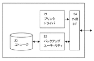
図2は本発明に係わるホストコンピュータの構成を説明する図である。 FIG. 2 is a diagram for explaining the configuration of the host computer according to the present invention.
同図において記号21はプリンタドライバ、記号22はバックアップユーティリティ、記号23はバックアップ情報ストレージ、記号24は外部インターフェースである。
In the figure,
プリンタドライバ21は印刷ジョブを生成し、外部インターフェース24を介して印刷装置に印刷ジョブを送信する。
The
バックアップユーティリティ22は印刷装置から受信した印刷装置の本体記憶情報を、バックアップ情報ストレージ23に記憶しておく。
The
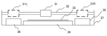
図3は本発明に係る印刷装置のプリントエンジンの構成を説明する図である。同図において記号31はキャリッジ、記号32はキャリッジをガイドするキャリッジシャフトである。キャリッジ31には不図示のインクジェットヘッドが搭載されており、不図示のキャリッジモータによって往復駆動される。記号33は被記録媒体、記号34は被記録媒体34を平面保持するためのプラテンである。被記録媒体33は不図示のLFローラによって把持され、キャリッジシャフト32と直交する方向に搬送される。記号35は該インクジェットヘッドの状態を維持するためのヘッドステーション、記号36は印刷中にヘッドの状態を維持するための予備吐出を行う予備吐ステーションである。ヘッドステーション35はインクジェットヘッドを吸引回復する機能、ヘッド表面を拭き取る機能、キャップする機能などを有している。印刷中にはキャリッジ31がヘッドステーション35の真上すなわち記号31Rの位置と、予備吐ステーション36の真上すなわち記号31Lの位置とで予備吐出動作を行う。これは、環境中に露出したインクに対する乾燥の影響を取り除くためである。従って、キャリッジ31の印刷中における移動範囲は予備吐出動作のために被記録媒体33の幅よりも広くなり、スループットを低下させる一因となっている。
FIG. 3 is a diagram illustrating the configuration of the print engine of the printing apparatus according to the present invention. In the figure,
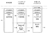
図4は本発明に係わる、保存される情報を保存場所に対応させて表記した図である。同図に置いて記号41は本体に記憶される全本体記憶情報。記号42はバックアップEEPROMに保存が可能なバックアップ可能情報。記号43は本体記憶情報の内、バックアップEEPROMには保存出来ない、あふれ情報。記号44は、バックアップEEPROMに保存出来なかったあふれ情報を含めて、外部にバックアップする為の外部バックアップ情報である。
FIG. 4 is a diagram showing information stored according to the present invention in correspondence with storage locations. In the figure,
保存される情報には、情報の保有者である印刷装置を特定する為の、IPアドレスと装置のシリアル番号が保存されている。 In the stored information, an IP address and a serial number of the device for specifying the printing device that is the owner of the information are stored.
また、外部バックアップ情報には、最も新しい情報を特定する為に、IPアドレスと装置のシリアル番号に加えて、保存時刻が保存されている。 In addition, in order to specify the newest information, the external backup information stores a storage time in addition to the IP address and the serial number of the apparatus.
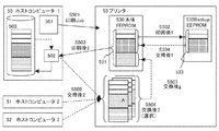
図5は本発明に係わる、基板交換に備えたデバイス情報をバックアップする機構を、時系列に情報の流れを追いながら説明した図である。同図において
記号50は印刷ジョブを生成してプリンタにデータを送信する、ホストコンピュータの1つである。
FIG. 5 is a diagram illustrating a mechanism for backing up device information in preparation for substrate replacement according to the present invention, following the flow of information in time series. In the figure, symbol 50 is one of host computers that generates a print job and transmits data to the printer.
記号501はホストコンピュータ50に搭載されるプリンタドライバ、記号502はバックアップユーティリティ、記号503はデータを保存する為のHDDである。
バックアップユーティリティ502は、プリンタから受信した本体記憶情報を、HDD503に保存する。
The
また、プリンタから保存データの送信要求があった場合には、保存している情報をプリンタに送信する。 Further, when there is a transmission request for stored data from the printer, the stored information is transmitted to the printer.
他にも、この構成と同様な、記号51で表されるホストコンピュータ2、記号52で表されるホストコンピュータ3がある。
In addition, there are a host computer 2 represented by symbol 51 and a
記号53は印刷装置であるプリンタである。記号530はプリンタ53に内包される本体EEPROMである。記号531は、本体EEPROM53に保存されている、本体記憶情報である。
Symbol 53 is a printer as a printing apparatus. A symbol 530 is a main body EEPROM included in the printer 53.
記号532はプリンタ53に内包され接続されているが、着脱可能なバックアップEEPROMである。記号533はバックアップEEPROM532に保存されている、バックアップ保存情報である。
A symbol 532 is included in and connected to the printer 53, but is a detachable backup EEPROM.
図中の記号S501からS508は、上記図5で説明した構成要素が、時系列にどのように関連し、本発明を構成するのかを表すシーケンス番号である。 Symbols S501 to S508 in the figure are sequence numbers representing how the components described in FIG. 5 are related in time series and constitute the present invention.
まず、情報の保存フェーズについて説明する。この時の情報の流れを、図中の実線で示した矢印で示す。 First, the information storage phase will be described. The flow of information at this time is indicated by arrows indicated by solid lines in the figure.
ホストコンピュータ50からプリンタ53に印刷ジョブが投入されると(ステップS501)、プリンタ53は印刷ジョブを元に印刷を行う。 When a print job is input from the host computer 50 to the printer 53 (step S501), the printer 53 performs printing based on the print job.
プリンタ53はジョブを印刷する際に、本体EEPROM530を更新する。 The printer 53 updates the main body EEPROM 530 when printing a job.
印刷ジョブが終了すると、本体EEPROMに保存されている情報を、バックアップEEPROM532に保存する(ステップS502)。 When the print job is finished, the information stored in the main body EEPROM is stored in the backup EEPROM 532 (step S502).
この時、本体EEPROMに保存されている全ての情報531を、バックアップEEPROMに保存する事は出来ないので、保存出来る情報だけを抽出し、バックアップ保存情報533としてバックアップEEPROM532に保存する。
At this time, since all the
プリンタ53は、バックアップEEPROM532に、情報を保存した後、ジョブ送信元のホストコンピュータ50に内包されるバックアップユーティリティ502に対して、プリンタ本体記憶情報を送信する(ステップS503)。
The printer 53 stores the information in the backup EEPROM 532, and then transmits the printer main body storage information to the
ホストコンピュータ50は、バックアップユーティリティ502によって受信したバックアップデータに、受信日時を付加して、HDD503に保存する。
The host computer 50 adds the reception date and time to the backup data received by the
次に、基板交換後の情報の復元フェーズについて説明する。 Next, the information restoration phase after board replacement will be described.
基板交換とは、対象となる電気基板が、破損・劣化などによって使用出来ない状態になった時に、別の動作可能な基板と交換する事を指す。 Substrate replacement refers to replacement of a target electric substrate with another operable substrate when it becomes unusable due to damage or deterioration.
この時、破損した電気基板に搭載され、取り外しが不可能な本体EEPROM530は、破損した基板と共に破棄される。 At this time, the main body EEPROM 530, which is mounted on the damaged electric board and cannot be removed, is discarded together with the damaged board.
もちろん保存されていた情報も破棄されてしまう。 Of course, the stored information is also discarded.
取りはずす時可能なバックアップEEPROMEPROM532は、基板交換前に一旦外され、交換後、再度接続する。 The backup EEPROM EPROM 532 that can be removed when it is removed is once removed before the board is replaced, and is connected again after the replacement.
このバックアップEEPROMについては、交換されていないので、基板交換前と同じ情報を保持している。 Since this backup EEPROM is not exchanged, it retains the same information as before the board exchange.
基板交換された後、基板と共に破棄されてしまった本体EEPROM530の情報を、復元しなければならない。 After the board is replaced, the information in the main body EEPROM 530 that has been discarded together with the board must be restored.
プリンタ53は、交換された基板で最初にブートする際に、自動的にバックアップEEPROM532に保持している情報を、交換後の基板に搭載されている本体EEPROM532にコピーし復元する。(ステップS504)
ただし、ステップS504では、バックアップEEPROMの容量が、全保存容量に対して少ない為に、必要な情報全てを復元する事が出来ない。あふれ出た情報についてはデフォルト値で初期化する。
When the printer 53 boots for the first time with the replaced board, it automatically copies and restores the information held in the backup EEPROM 532 to the main body EEPROM 532 mounted on the replaced board. (Step S504)
However, in step S504, since the capacity of the backup EEPROM is small with respect to the total storage capacity, all necessary information cannot be restored. The overflow information is initialized with default values.
その後、プリンタ53はネットワーク上のホストコンピュータに対して,IPアドレスとシリアル番号をキーにしてブロードキャストによる保存情報の問い合わせをおこなう。 Thereafter, the printer 53 makes an inquiry about the stored information by broadcast to the host computer on the network using the IP address and serial number as keys.
各ホストコンピュータに内包されている、バックアップユーティリティ(例502)は問い合わせに呼応して自HDD(例503)上に該当する情報が保存されていればこれを問い合わせ元のプリンタに送付する(ステップS505)。 In response to the inquiry, the backup utility (example 502) included in each host computer sends the corresponding information to the inquiry source printer if the corresponding information is stored on its own HDD (example 503) (step S505). ).
プリンタ53は複数の応答があればその中で最も時刻情報が新しい情報を選択肢(ステップS506)し、本体EEPROM530に対して、復元する(ステップS507)。 If there are a plurality of responses, the printer 53 selects the information having the newest time information (step S506) and restores it to the main body EEPROM 530 (step S507).
1 ホストコンピュータ
11 外部インターフェース
12 本体EEPROM
13 バックアップEEPROM
14 操作パネル
21 プリンタドライバ
22 バックアップユーティリティ
23 バックアップ情報ストレージ
24 外部インターフェース
3 インクジェットプリントエンジン
31 キャリッジ
32 キャリッジシャフト
33 被記録媒体
34 プラテン
35 ヘッドステーション
36 予備吐ステーション
37 シャーシ
41 本体記憶情報
42 バックアップ可能情報
43 あふれ情報
44 外部バックアップ情報
50 ホストコンピュータ1
501 プリンタドライバ
502 バックアップユーティリティ
503 HDD
51 ホストコンピュータ2
52 ホストコンピュータ3
53 プリンタ
530 本体EEPROM
531 本体記憶情報
532 バックアップEEPROM
533 バックアップ保存情報
1
13 Backup EEPROM
14
501
51 Host computer 2
52
53 Printer 530 Main Body EEPROM
531 Main unit storage information 532 Backup EEPROM
533 Backup storage information
Claims (2)
Priority Applications (1)
| Application Number | Priority Date | Filing Date | Title |
|---|---|---|---|
| JP2009282635A JP2011123790A (en) | 2009-12-14 | 2009-12-14 | Method of storing information |
Applications Claiming Priority (1)
| Application Number | Priority Date | Filing Date | Title |
|---|---|---|---|
| JP2009282635A JP2011123790A (en) | 2009-12-14 | 2009-12-14 | Method of storing information |
Publications (1)
| Publication Number | Publication Date |
|---|---|
| JP2011123790A true JP2011123790A (en) | 2011-06-23 |
Family
ID=44287600
Family Applications (1)
| Application Number | Title | Priority Date | Filing Date |
|---|---|---|---|
| JP2009282635A Pending JP2011123790A (en) | 2009-12-14 | 2009-12-14 | Method of storing information |
Country Status (1)
| Country | Link |
|---|---|
| JP (1) | JP2011123790A (en) |
Cited By (3)
| Publication number | Priority date | Publication date | Assignee | Title |
|---|---|---|---|---|
| JP2016071445A (en) * | 2014-09-26 | 2016-05-09 | 京セラドキュメントソリューションズ株式会社 | Image forming apparatus |
| JP2019149763A (en) * | 2018-02-28 | 2019-09-05 | オムロン株式会社 | Data processing method, control system, and control device |
| US10486393B2 (en) | 2014-10-09 | 2019-11-26 | Materion Corporation | Devices including metal laminate with metallurgical bonds and reduced-density metal core layer |
-
2009
- 2009-12-14 JP JP2009282635A patent/JP2011123790A/en active Pending
Cited By (3)
| Publication number | Priority date | Publication date | Assignee | Title |
|---|---|---|---|---|
| JP2016071445A (en) * | 2014-09-26 | 2016-05-09 | 京セラドキュメントソリューションズ株式会社 | Image forming apparatus |
| US10486393B2 (en) | 2014-10-09 | 2019-11-26 | Materion Corporation | Devices including metal laminate with metallurgical bonds and reduced-density metal core layer |
| JP2019149763A (en) * | 2018-02-28 | 2019-09-05 | オムロン株式会社 | Data processing method, control system, and control device |
Similar Documents
| Publication | Publication Date | Title |
|---|---|---|
| JP5163408B2 (en) | Information processing device | |
| JP2011123790A (en) | Method of storing information | |
| US20170270395A1 (en) | Electronic apparatus and method of managing status information of the same | |
| US20160132261A1 (en) | Storage system which makes backups of input data | |
| JP4646751B2 (en) | Image forming apparatus, functional component determination method, control program, and storage medium | |
| CN109814813B (en) | Apparatus having a plurality of memories, control method, and storage medium | |
| JP2007001090A (en) | Data backup system for image forming apparatus, image forming apparatus, and data backup method | |
| JP6111918B2 (en) | Image processing apparatus, image processing system, and program | |
| JP4781184B2 (en) | Image forming apparatus and method of controlling image forming apparatus | |
| JP5809221B2 (en) | PRINT CONTROL DEVICE, INKJET RECORDING DEVICE, PRINT CONTROL METHOD, PROGRAM, AND PRINT SYSTEM | |
| JP2017035836A (en) | Recording device and control method for the same | |
| JP2009301512A (en) | Host device and information restoration method | |
| US11645026B2 (en) | Image processing apparatus that generates a job log after recovery from power-off that prevents successful ending of a job, method, and non-transitory computer-readable storage medium for storing program | |
| JP4018514B2 (en) | Recording apparatus, power supply control method, storage medium storing computer-readable program, and program | |
| JP2020131659A (en) | Print device, information processing method and program | |
| US9519552B2 (en) | Image forming apparatus which executes rebuild processes | |
| JP2006243859A (en) | Print system | |
| JP2005238521A (en) | Printing apparatus, printing control method, program, and recording medium | |
| JP2009100103A (en) | Printing device | |
| JP5697104B2 (en) | Printing system, printing method, printing control apparatus, inkjet recording apparatus, printing control method, and program | |
| JP2012220964A (en) | Information processing system and backup method of information processing system | |
| CN100446989C (en) | Imaging device capable of ink ribbon fault record management and ribbon fault record management method | |
| JP6213438B2 (en) | Image forming apparatus | |
| JP2015036861A (en) | Storage controller, storage controller control method, and program | |
| JP2012032912A (en) | Information management device |