JP2011123738A - Connection system of network, terminal unit, network control unit, method of connecting network, program and recording medium - Google Patents
Connection system of network, terminal unit, network control unit, method of connecting network, program and recording medium Download PDFInfo
- Publication number
- JP2011123738A JP2011123738A JP2009281840A JP2009281840A JP2011123738A JP 2011123738 A JP2011123738 A JP 2011123738A JP 2009281840 A JP2009281840 A JP 2009281840A JP 2009281840 A JP2009281840 A JP 2009281840A JP 2011123738 A JP2011123738 A JP 2011123738A
- Authority
- JP
- Japan
- Prior art keywords
- network
- terminal device
- energy saving
- network connection
- saving state
- Prior art date
- Legal status (The legal status is an assumption and is not a legal conclusion. Google has not performed a legal analysis and makes no representation as to the accuracy of the status listed.)
- Withdrawn
Links
Images
Landscapes
- Power Sources (AREA)
Abstract
Description
本発明は、ネットワークの接続システム、端末装置、ネットワーク制御装置、ネットワークの接続方法、プログラム及び記録媒体に関し、特に端末装置が省エネ状態の場合に消費電力をさらに低減させるネットワークの接続システム、端末装置、ネットワーク制御装置、ネットワークの接続方法、プログラム及び記録媒体に関する。 The present invention relates to a network connection system, a terminal device, a network control device, a network connection method, a program, and a recording medium, and more particularly to a network connection system, a terminal device, and a network connection system that further reduce power consumption when the terminal device is in an energy saving state. The present invention relates to a network control device, a network connection method, a program, and a recording medium.
近年のネットワーク技術の革新は目覚しく、転送性能も急激に向上している。ネットワークの規格策定に関しては、10Gbps(Giga bit per Second)は既に策定され、100Gbpsの策定が進んでおり、有線ネットワークの世界では性能向上が止まるところを知らない。世間一般に敷かれているネットワーク環境を見渡しても、つい先日まではやっと100Mbpsの環境で統一された感があったが、近年では1Gbpsのネットワーク環境を構築する場面も多くなってきた。 In recent years, network technology innovation has been remarkable, and transfer performance has also improved rapidly. Regarding network standards, 10 Gbps (Giga bit per Second) has already been formulated, and 100 Gbps is being developed, and we do not know where the performance improvement will stop in the world of wired networks. Looking at the network environment that is open to the general public, there was a feeling that it was finally unified in the 100Mbps environment until the other day, but in recent years there have been many occasions to construct a 1Gbps network environment.
一方、ネットワーク性能が向上する反面、今や当然となったネットワーク接続機能を搭載したPC(Personal Computer)やプリンタ、MFP(Multi Function Printer)等の端末装置、LAN(Local Area Network)スイッチやルーター等のネットワーク機器の消費電力は増加する傾向にある。近年の地球温暖化等の環境問題に対応するためには、オフィス機器の消費電力低減、特にネットワーク機器の消費電力を低減することが求められる。 On the other hand, while network performance is improved, terminal devices such as PCs (Personal Computers), printers, MFPs (Multi Function Printers), and LAN (Local Area Network) switches and routers equipped with network connection functions that have become natural nowadays The power consumption of network devices tends to increase. In order to cope with environmental problems such as global warming in recent years, it is required to reduce the power consumption of office equipment, particularly the power consumption of network equipment.
ここで、上記プリンタなどのオフィス機器は、その動作時間よりも待機時間が大半を占めるため、待機時はCPU(Central Processing Unit)やROM(Read Only Memory)の電源を切ったり、消費電力を極力低減した省エネモードに移行したりする制御を行い、機器待機時の消費電力低減を実現している。 Here, the office devices such as the above printers occupy most of the standby time rather than the operation time. Therefore, during standby, the CPU (Central Processing Unit) and ROM (Read Only Memory) are turned off and the power consumption is minimized. Controls such as shifting to a reduced energy-saving mode are implemented to reduce power consumption when the equipment is on standby.
しかし、ネットワーク接続機能を搭載したプリンタやMFP等は、印字動作以外にも機器情報取得ツールといったアプリケーション機能におけるネットワーク応答動作で電力を消費している。ネットワークの世界では、ホストから端末装置に対して定期的に機器情報の応答が要求され、端末装置が省エネ状態でもネットワーク部分は動作させておくことが必要である。そこで従来は、ネットワーク動作に関係の無い部分の電源を切って、消費電力を低減していた(図8参照)。 However, printers and MFPs equipped with a network connection function consume power in a network response operation in an application function such as a device information acquisition tool in addition to a printing operation. In the network world, a response of device information is periodically requested from the host to the terminal device, and it is necessary to operate the network portion even when the terminal device is in an energy saving state. Therefore, conventionally, the power consumption is reduced by turning off the power of the portion unrelated to the network operation (see FIG. 8).
ネットワーク部分の省エネに関する技術としては、ネットワークフィルタの機能をオンオフ制御するメインCPUが、システムの電源投入後のレディ状態時にはネットワークを介して転送されてくるIPパケットのTCPヘッダに含まれる所定のフラグを判別してパケットタイプフィルタ機能をオフ状態にして省エネ効果を得る方法が提案されている(特許文献1)。 As a technology related to energy saving in the network part, the main CPU that controls on / off of the network filter function sets a predetermined flag included in the TCP header of the IP packet transferred via the network when the system is in a ready state. A method has been proposed in which the packet type filter function is turned off and an energy saving effect is obtained (Patent Document 1).
ところで上記ネットワーク応答動作で電力を消費するのは、ネットワークデータを制御するMAC(Media Access Control)や物理層(Physical Layer)デバイスのPHYである。特に転送性能が向上するに連れて消費電力が上がるのはPHYであり、PHYの消費電力低減がネットワーク動作における消費電力削減に効果的である。 By the way, the network response operation consumes power by a MAC (Media Access Control) for controlling network data and a PHY of a physical layer device. In particular, it is the PHY that increases the power consumption as the transfer performance improves, and reducing the power consumption of the PHY is effective in reducing the power consumption in the network operation.
近年のようにネットワークを1Gbpsの転送性能で構築した場合、10Mbpsや100Mbpsの場合と比較して2倍の電力を消費する。これは、PHYデバイスの消費電力が1Gbpsになると10Mbpsや100Mbpsから約2倍になることに起因している。 When a network is constructed with 1 Gbps transfer performance as in recent years, it consumes twice as much power as 10 Mbps or 100 Mbps. This is due to the fact that when the power consumption of the PHY device is 1 Gbps, it doubles from 10 Mbps or 100 Mbps.
消費電力を低減する方法としては、省エネ時にLANのリンク速度を落とすことが考えられる。例えば、機器動作時は1Gbpsで送受信し、省エネ時は10Mbps、若しくは100Mbpsに設定するといった具合である。 As a method for reducing the power consumption, it is conceivable to reduce the LAN link speed during energy saving. For example, 1 Gbps is transmitted and received when the device is operating, and 10 Mbps or 100 Mbps is set when saving energy.
上記特許文献1記載の発明は、あるモジュールのオンオフをネットワークパケットにより判別するものであるが、LANのリンク速度変更による消費電力低減と比較すると効果は低い。 The invention described in Patent Document 1 discriminates on / off of a certain module by a network packet, but its effect is low as compared with power consumption reduction by changing the LAN link speed.
また、LANのリンク速度変更による消費電力低減は効果が高いが、LANスイッチ側のスパニングツリー機能により、使用には制約が生じる。つまり、スパニングツリー機能が働くことにより、ネットワークに負荷がかかり、実質的な転送性能が落ちるため、リアルタイムで転送が必要なケース(例えば動画転送やスキャナデータの転送など)では使えないことが予想される。従って、実際のネットワーク環境ではLANのリンク速度を落とすことが出来ず、機器のネットワーク部分に関しては、省エネ時でも動作時と同等の電力を消費することになる。 In addition, power consumption reduction by changing the link speed of the LAN is highly effective, but use is restricted by the spanning tree function on the LAN switch side. In other words, because the spanning tree function works, the network is overloaded and the actual transfer performance drops, so it is expected that it cannot be used in cases where transfer in real time is required (for example, video transfer or scanner data transfer). The Therefore, in an actual network environment, the LAN link speed cannot be reduced, and the network portion of the device consumes power equivalent to that during operation even during energy saving.
本発明はこのような状況に鑑みてなされたものであり、ネットワーク接続機能を備える端末装置が省エネ状態の場合に、ネットワーク動作に関係の無い部分の電源を切る他、ネットワーク動作に関わる部分の消費電力も極力低減することを目的としている。 The present invention has been made in view of such a situation. When a terminal device having a network connection function is in an energy saving state, the power is turned off to a part not related to the network operation, and a part related to the network operation is consumed. The purpose is to reduce power as much as possible.
本発明に係るネットワークの接続システムは、ネットワーク接続機能を備えた端末装置と接続するネットワーク制御装置を複数備えるネットワークの接続システムであって、前記端末装置は、省エネ状態に以降する時に、前記ネットワーク制御装置と接続するネットワークのスピードを再設定するスピード設定手段を備えることを特徴とする。 A network connection system according to the present invention is a network connection system including a plurality of network control devices connected to a terminal device having a network connection function, and the terminal device is configured to control the network control when the terminal device goes into an energy saving state. Speed setting means for resetting the speed of the network connected to the apparatus is provided.
本発明に係る端末装置第は、ネットワーク接続機能を備えた端末装置と接続するネットワーク制御装置を複数備えるネットワークの接続システムの前記端末装置であって、省エネ状態に以降する時に、前記ネットワーク制御装置と接続するネットワークのスピードを再設定するスピード設定手段を備えることを特徴とする。 A terminal device according to the present invention is the terminal device of a network connection system comprising a plurality of network control devices connected to a terminal device having a network connection function, and when the energy saving state is followed, the network control device Speed setting means for resetting the speed of the network to be connected is provided.
本発明に係るネットワーク制御装置は、ネットワーク接続機能を備えた端末装置と接続するネットワーク制御装置を複数備えるネットワークの接続システムの前記ネットワーク制御装置であって、前記端末装置から、前記端末装置が省エネ状態に入る旨の通知を受けた場合は、前記ネットワーク制御装置が有するスパニングツリー機能を無効にすることを特徴とする。 A network control device according to the present invention is a network connection device of a network connection system including a plurality of network control devices connected to a terminal device having a network connection function, wherein the terminal device is in an energy saving state. When the notification of entering is received, the spanning tree function of the network control device is invalidated.
本発明に係る第1のネットワークの接続方法は、ネットワーク接続機能を備えた端末装置と接続するネットワーク制御装置を複数備えるネットワークの接続方法であって、前記端末装置は、省エネ状態に以降する時に、前記ネットワーク制御装置と接続するネットワークのスピードを再設定するステップを備えることを特徴とする。 A first network connection method according to the present invention is a network connection method including a plurality of network control devices connected to a terminal device having a network connection function, and the terminal device is in an energy-saving state, The step of resetting the speed of the network connected to the network control device is provided.
本発明に係る第2のネットワークの接続方法は、上記第1の接続方法において、前記ネットワーク制御装置は、前記端末装置から、前記端末装置が省エネ状態に入る旨の通知を受けた場合は、前記ネットワーク制御装置が有するスパニングツリー機能を無効にするステップを備えることを特徴とする。 The second network connection method according to the present invention is the network connection device according to the first connection method, wherein the network control device receives a notification from the terminal device that the terminal device enters an energy saving state. The step of invalidating the spanning tree function of the network control device is provided.
本発明に係る第1のネットワークの接続プログラムは、ネットワーク接続機能を備えた端末装置と接続するネットワーク制御装置を複数備えるネットワークの接続プログラムであって、前記端末装置は、省エネ状態に以降する時に、前記ネットワーク制御装置と接続するネットワークのスピードを再設定する処理を、前記端末装置であるコンピュータに実行させることを特徴とする。 The first network connection program according to the present invention is a network connection program including a plurality of network control devices connected to a terminal device having a network connection function, and the terminal device is in an energy-saving state, A process of resetting a speed of a network connected to the network control device is executed by a computer that is the terminal device.
本発明に係る第2のネットワークの接続プログラムは、上記第1の接続プログラムにおいて、前記ネットワーク制御装置は、前記端末装置から、前記端末装置が省エネ状態に入る旨の通知を受けた場合は、前記ネットワーク制御装置が有するスパニングツリー機能を無効にする処理を、前記ネットワーク制御装置であるコンピュータに実行させることを特徴とする。 In the first network connection program according to the second network connection program of the present invention, when the network control device receives a notification from the terminal device that the terminal device enters an energy saving state, A process of invalidating a spanning tree function of a network control apparatus is executed by a computer that is the network control apparatus.
本発明に係る記録媒体は、上記本発明に係る第1又は第2のネットワークの接続プログラムの処理を記録するコンピュータ読取り可能な記録媒体である。 The recording medium according to the present invention is a computer-readable recording medium for recording the processing of the first or second network connection program according to the present invention.
本発明によれば、ネットワーク接続機能を備える端末装置が省エネ状態の場合に、ネットワーク動作に関係の無い部分の電源を切る他、ネットワーク動作に関わる部分の消費電力も極力低減することが出来る。 According to the present invention, when a terminal device having a network connection function is in an energy saving state, the power consumption of a portion related to the network operation can be reduced as much as possible in addition to turning off the power of the portion not related to the network operation.
以下に、本発明の実施形態について図面を用いて詳細に説明する。なお、以下に述べる実施形態は、本発明の好適な実施形態であるから、技術的に好ましい種々の限定が付されているが、本発明の範囲は、以下の説明において特に本発明を限定する旨の記載がない限り、これらの態様に限られるものではない。 Embodiments of the present invention will be described below in detail with reference to the drawings. The embodiments described below are preferred embodiments of the present invention, and thus various technically preferable limitations are given. However, the scope of the present invention is particularly limited in the following description. As long as there is no description of the effect, it is not restricted to these aspects.
本実施形態では、ネットワーク制御装置の一例として、LANスイッチを用いる。ネットワーク接続機能を備えた端末装置は、一例として、PC(パーソナルコンピュータ)や画像形成装置(複写機、MFP)が想定される。 In this embodiment, a LAN switch is used as an example of a network control device. As an example, a terminal device having a network connection function is assumed to be a PC (personal computer) or an image forming apparatus (copying machine, MFP).
本実施形態において、省エネモード(省エネ、省エネ状態とも称す)とは、通常の動作状態よりも消費電力が少なくなるよう電源を制御した状態を示す。 In the present embodiment, the energy saving mode (also referred to as energy saving or energy saving state) indicates a state in which the power source is controlled so that the power consumption is less than that in the normal operation state.
本明細書において、LANのリンク速度は、「ネットワーク(の)スピード」、「リンクスピード」や、単に「リンク速度」、「スピード」、「転送速度」とも称す。 In this specification, the LAN link speed is also referred to as “network speed”, “link speed”, or simply “link speed”, “speed”, and “transfer speed”.
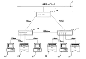
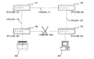
(全体構成)
まず、本実施形態で想定される一般的なネットワーク接続の一例を図1に示す。LANスイッチ1は1A、1B、1Cの3台がそれぞれ相互にループを作る形で接続されている。1A−1B間は1Gbps、1A−1C間は1Gbps、1B−1C間は100Mbpsのリンク速度で接続されている。
(overall structure)
First, an example of a general network connection assumed in this embodiment is shown in FIG. In the LAN switch 1, three
LANスイッチ1Bには図示されている通り、ネットワーク接続機能を備えた端末装置2A、2B、2Cが、またLANスイッチ1Cにはネットワーク接続機能を備えた端末装置2D、2E、2Fが、それぞれ1Gbpsのリンク速度で接続されている。
As shown in the figure, the
この状態では、宛先の不明なネットワークパケットが3台のLANスイッチ1A〜1Cの間で永久的にループしてしまうことになる。そこでLANスイッチ1には、スパニングツリーという機能が搭載され、パケットのループを防止する。
In this state, a network packet whose destination is unknown is permanently looped between the three
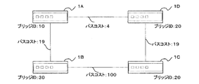
(スパニングツリー機能)
ここでスパニングツリー機能の動作概要を説明する。図4及び図5はスパニングツリー機能を用いてネットワーク経路を構築する方法を説明するための図である。図4に示すように、LANスイッチ4台(1A〜1D)がお互いに接続されており、各LANスイッチには複数台の端末機器(図示せず)が接続されているものとする。
(Spanning tree function)
Here, an outline of the operation of the spanning tree function will be described. 4 and 5 are diagrams for explaining a method of constructing a network path using the spanning tree function. As shown in FIG. 4, four LAN switches (1A to 1D) are connected to each other, and a plurality of terminal devices (not shown) are connected to each LAN switch.
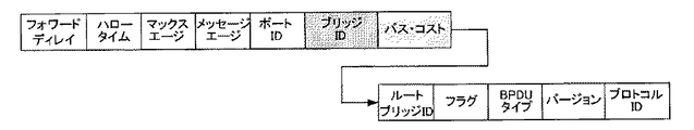
各LANスイッチに割り振られたブリッジIDはユーザ(ネットワーク管理者)が任意に付加した値であり、その値が一番小さいLANスイッチがそのネットワークグループのルートブリッジとなる。ルートブリッジとは、属しているネットワークグループを制御・管理する機器である。 The bridge ID assigned to each LAN switch is a value arbitrarily added by the user (network administrator), and the LAN switch having the smallest value becomes the root bridge of the network group. A root bridge is a device that controls and manages a network group to which it belongs.
バスコストとは、そのネットワーク経路の転送速度を意味する。例えば、転送速度が10Mbpsは100、100Mbpsは19、1Gbpsは4といった具合である。バスコストもその値が小さいほど優先される。 The bus cost means the transfer speed of the network route. For example, the transfer rate is 100 for 10 Mbps, 19 for 100 Mbps, 4 for 1 Gbps, and so on. The lower the bus cost, the higher the priority.
どの経路を遮断するかは、上述したブリッジIDとバスコストによって判断される。例えば、LANスイッチ1Aがルートブリッジだとすると、LANスイッチAは自分自身に接続されている端末機器の情報と各LANスイッチからの情報を入手する。
Which route is to be blocked is determined by the above-described bridge ID and bus cost. For example, if the
LANスイッチ1Bは、自分のブリッジID(30)とLANスイッチ1Aの接続経路のバスコスト(19)、LANスイッチ1Cの接続経路のバスコスト(100)から、それぞれの総和を算出する。即ち、30+19=49、30+100=130といった具合に算出する。このようにしてそれぞれのLANスイッチが自身の接続経路の値を算出し、ルートブリッジであるLANスイッチ1Aに情報を集める。
The
LANスイッチ1Aは、収集した情報を基に、ネットワークグループの各経路の中でどの経路の値が一番大きいかを割り出し、その経路を遮断するよう通知する。ここでは、LANスイッチ1BとLANスイッチ1Cの接続経路の算出値が一番大きい為、図5に示すように、かかる経路を遮断してループを防止する。
Based on the collected information, the
図6はスパニングツリー機能を実行した場合に、各LANスイッチがルートブリッジ宛に送出するパケットデータのフォーマットにブリッジIDとバスコストを加えた図である。これはBPDU(BridgeProtocol Data Unit)として規格化されている。 FIG. 6 is a diagram in which a bridge ID and a bus cost are added to the format of packet data transmitted from each LAN switch to the root bridge when the spanning tree function is executed. This is standardized as BPDU (Bridge Protocol Data Unit).
(リンクスピードを落とすことによる消費電力低減)
本実施形態に係るネットワークの接続システムでは、端末装置2が省エネ状態に移行した場合に、CPUやROM等のネットワーク動作に関係の無い部分の電源を切る他、ネットワーク動作に関係のある部分の消費電力も低減することで、消費電力低減の効果を高める。具体的には、端末装置2とLANスイッチ1とのリンクスピードを落とす。ここで、リンクスピードを落とす動作は消費電力低減に有効であるが、LANスイッチ1のスパニングツリー機能により使用に制約が生じる場合がある。つまり、上述したように、スパニングツリー機能が働くことによりネットワークに負荷がかかり、実質的な転送性能が落ちるため、リアルタイムで転送が必要なケース(例えば動画転送やスキャナデータの転送など)では使えないことが予想される。
(Reduces power consumption by reducing link speed)
In the network connection system according to the present embodiment, when the terminal device 2 shifts to the energy saving state, the CPU and the ROM, etc., which are not related to the network operation are turned off, and the parts related to the network operation are consumed. By reducing power, the effect of reducing power consumption is enhanced. Specifically, the link speed between the terminal device 2 and the LAN switch 1 is reduced. Here, the operation of reducing the link speed is effective in reducing power consumption, but there are cases where the use is restricted by the spanning tree function of the LAN switch 1. In other words, as mentioned above, the spanning tree function works, and the network is overloaded and the substantial transfer performance is reduced. Therefore, it cannot be used in cases where transfer in real time is required (for example, moving image transfer or scanner data transfer). It is expected that.
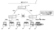
図1に示した本実施形態に係るネットワークにおいてスパニングツリー機能が動作した場合について図2を用いて説明する。上述したように、スパニングツリー機能はLANスイッチ間(図1では、1A、1B、1Cの間)でパケットが周り続けるのを防ぐために用いられる。スパニングツリー機能は各々のLANスイッチが管理しているネットワーク経路に変更が生じた際、そのネットワークの経路探索を始め、パケットが周り続けないように、経路の一部を遮断する。 A case where the spanning tree function operates in the network according to the present embodiment shown in FIG. 1 will be described with reference to FIG. As described above, the spanning tree function is used to prevent the packet from continuing around between the LAN switches (between 1A, 1B, and 1C in FIG. 1). When a change occurs in the network route managed by each LAN switch, the spanning tree function starts a route search of the network and blocks a part of the route so that the packet does not continue around.
上述の経路計算方法を用いると、図2の例ではLANスイッチ1Bと1Cの接続が遮断され、必ずLANスイッチAを通してパケットをやり取りすることにより、パケットの永久ループを防止する。 When the above route calculation method is used, in the example of FIG. 2, the connection between the LAN switches 1B and 1C is cut off, and packets are always exchanged through the LAN switch A, thereby preventing a permanent loop of packets.
このとき、端末装置2Fが省エネ状態に入る際、LANの転送速度(リンク速度)を1Gbpsから100Mbpsに変更したとする。その場合、一旦リンクを切ることになり、LANスイッチ側はネットワーク構成が変更されたと判断し、その度にネットワーク経路の探索を始めるため、ネットワークのトラフィックが増大し、実使用には適していない。または使用に制約が生じることになる。
At this time, when the
従って、実際のネットワーク環境では転送速度を落とすことが出来ず、機器のネットワーク部分に関しては省エネ時でも動作時と同等の電力を消費することになっていた。 Therefore, the transfer speed cannot be reduced in an actual network environment, and the network portion of the device consumes the same amount of power as when it is operating even during energy saving.
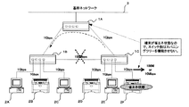
そこで、本実施形態では、図2と同様にリンクを落とす(接続経路を遮断する)ことに変わりはないが、省エネ状態になる際に、前もってLANスイッチ側に省エネ移行の旨を通知することで、LANスイッチ側のスパニングツリー機能を無効にすることで上記問題を回避することも可能である(図3)。 Thus, in this embodiment, the link is dropped (blocking the connection path) as in FIG. 2, but when the energy saving state is entered, the LAN switch side is notified in advance of the energy saving transition. It is also possible to avoid the above problem by disabling the spanning tree function on the LAN switch side (FIG. 3).
更にLANスイッチと省エネ状態の端末装置間のリンク速度を落とすことで消費電力を低減することも考え得る。例えば1Gbpsから100Mbps、または10Mbpsに落とすといった具合である。なお、このような場合でも、省エネ移行の旨が通知されているLANスイッチ側は、端末装置側が省エネ状態であることが分かっているので、リンクスピード変更によるスパニングツリー機能は動作させない。 Further, it is conceivable to reduce power consumption by reducing the link speed between the LAN switch and the energy saving terminal device. For example, it is reduced from 1 Gbps to 100 Mbps or 10 Mbps. Even in such a case, the LAN switch side that is notified of the energy saving transition does not operate the spanning tree function by changing the link speed because it is known that the terminal device side is in the energy saving state.
リンク速度を段階的に落とす場合、例えば100Mbpsに落とした時に他のネットワーク系の要因によりスパニングツリーを機能させなければならないとなった場合、LANスイッチは初期に取得した端末装置の情報(例えばネットワークの対応スピードは1Gbps等)でスパニングツリー機能の経路探索を行う。このことにより、ユーザの生産性(ネットワークスピードが最速であることによるトータルの処理時間の短縮)を維持することができる。 When the link speed is gradually reduced, for example, when the spanning tree has to function due to other network factors when the link speed is reduced to 100 Mbps, the LAN switch obtains the terminal device information (for example, the network Spanning tree function path search is performed at a corresponding speed of 1 Gbps or the like. As a result, user productivity (a reduction in total processing time due to the highest network speed) can be maintained.
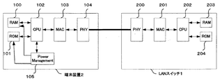
(各装置の構成)
次に、本実施形態に係る端末装置と、LANスイッチ、それぞれの機能ブロック構成の一例を図7に示す。
(Configuration of each device)
Next, FIG. 7 shows an example of functional block configurations of the terminal device and the LAN switch according to the present embodiment.
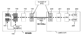
端末装置2は、装置全体の動作を制御するCPU102を備え、CPU102には、プログラムを格納するROM101、ワーク領域を確保するRAM(Random Access Memory)100が接続されている。ネットワーク制御部分は、送受信するネットワークデータを制御するMAC(MediaAccess Controller)103、物理層デバイスのPHY104から構成される。端末装置2が省エネ状態の時に装置全体の電源を制御するPower Management部105が実装されている。
The terminal device 2 includes a
一方、LANスイッチ1は、基本的な構成は端末装置2と同じであるが、省エネ状態の電源制御を行う必要がないので、PowerManagement部が無い構成となる。 On the other hand, the basic configuration of the LAN switch 1 is the same as that of the terminal device 2, but there is no need to perform power-saving control in an energy saving state, and therefore there is no configuration of the PowerManagement section.
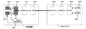
上述したように、端末装置の従来の省エネモードでは、CPU、ROM、RAM、及びその他ネットワーク動作に関係の無いモジュールの電源をオフすることで消費電力低減を図っていた。図8に、従来の省エネ状態となっている端末装置を示す。端末装置のCPU102、ROM101、RAM100の部分がグレーになっており、電源オフの状態を示している。
As described above, in the conventional energy saving mode of the terminal device, power consumption is reduced by turning off the power of the CPU, ROM, RAM, and other modules not related to the network operation. FIG. 8 shows a conventional terminal device in an energy saving state. The portions of the
MAC103やPHY104といったネットワーク部は、LANスイッチ1からデータが入力されたときに復帰する必要があるため、電源はオンにしておく必要がある。LANスイッチ1も同様に、各モジュールの電源をオフすることは出来なかった。その為、図8に示す例では、端末装置2の消費電力や、ネットワーク全体の消費電力低減効果は限定的であった。
The network unit such as the
本実施形態に係る省エネ動作を図9に示す。端末装置2とLANスイッチ1間のリンク速度を落とすことで、消費電力を画期的に低減させた。 An energy saving operation according to the present embodiment is shown in FIG. By reducing the link speed between the terminal device 2 and the LAN switch 1, the power consumption has been dramatically reduced.
端末装置2は、省エネ状態になる前にその旨をLANスイッチ1に通知し、LANスイッチ1がPHYのスピード(リンク速度)を落とすことで端末装置側の消費電力を下げている。また、リンク速度を落とすことで、LANスイッチ1の消費電力も低減される効果がある。 The terminal device 2 notifies the LAN switch 1 before it enters the energy saving state, and the LAN switch 1 reduces the PHY speed (link speed) to reduce the power consumption on the terminal device side. In addition, the power consumption of the LAN switch 1 can be reduced by reducing the link speed.
リンクスピードを落とす方法としては、LANスイッチ1からネゴシエーションを掛ける方法が考えられる。端末装置2から、省エネ状態に入る旨の通知を受けたLANスイッチ1は、その直後からスピード再設定の為のネゴシエーション機能(スピード設定手段)を走らせる。 As a method of reducing the link speed, a method of negotiating from the LAN switch 1 can be considered. The LAN switch 1 that has received a notification from the terminal device 2 to enter the energy saving state runs a negotiation function (speed setting means) for speed reset immediately after that.
ネゴシエーションはお互いの持っている機能を通知し合い、通常であればお互いが持っている最速のスピードで接続するよう制御する。しかし、本実施形態では、消費電力低減を目的にするため、最も遅いスピードに再設定する。若しくは、消費電力が最も低くなるスピード情報を端末装置2が持っており、その情報を基にスピード設定することも考えられる。 Negotiations notify each other of the functions they have, and usually control them to connect at the fastest speed they have. However, in this embodiment, in order to reduce power consumption, the speed is reset to the slowest speed. Alternatively, the terminal device 2 has speed information that consumes the lowest power, and it is conceivable to set the speed based on the information.
図9に示す例では、リンクスピードを、通常動作では1Gbpsで接続しているが、省エネ状態では100Mbps、若しくは10Mbpsで再接続している。 In the example shown in FIG. 9, the link speed is connected at 1 Gbps in the normal operation, but is reconnected at 100 Mbps or 10 Mbps in the energy saving state.
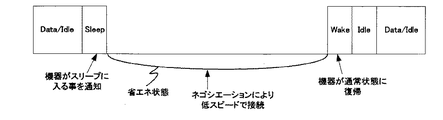
図10は、省エネ状態に移行する時、省エネ中、復帰する時、の各動作を概念的に示した図である。端末装置2は、データ送受信時、若しくはIDLE状態から省エネ状態に入る際に、LANスイッチ1に対して、前もってその旨を通知するコマンド(図10中ではSleepコマンド)を送信する。 FIG. 10 is a diagram conceptually showing each operation when shifting to the energy saving state, during energy saving, and when returning. The terminal device 2 transmits a command (Sleep command in FIG. 10) to notify the LAN switch 1 in advance at the time of data transmission / reception or when entering the energy saving state from the IDLE state.
Sleepコマンドを受け取ったLANスイッチ1は、そのポートに接続されている端末装置2が省エネ状態になったことを確認し、スパニングツリー機能を持っていれば、それを機能させないようにする。端末装置2は、PowerManagement部105以外のモジュールの電源をオフする。
Upon receiving the Sleep command, the LAN switch 1 confirms that the terminal device 2 connected to the port has entered an energy saving state, and if it has a spanning tree function, prevents it from functioning. The terminal device 2 turns off the power of the modules other than the
省エネ状態の期間中は低スピードのリンク速度で接続される。省エネ状態中は、次にネットワークパケットを送受信するまで各モジュールの電源をオフした状態を維持する。 During the energy saving state, connection is made at a low link speed. During the energy saving state, the power of each module is kept off until the next network packet is transmitted / received.
端末装置2宛のネットワークデータをLANスイッチ1が受信した場合は、LANスイッチ1から端末装置2に対してWake信号を送信する。若しくは、端末装置2からユーザ操作によって省エネ状態から復帰する場合は、端末装置2からLANスイッチ1に対してWake信号を送信する。 When the LAN switch 1 receives network data addressed to the terminal device 2, a wake signal is transmitted from the LAN switch 1 to the terminal device 2. Alternatively, when returning from the energy saving state by a user operation from the terminal device 2, a Wake signal is transmitted from the terminal device 2 to the LAN switch 1.
端末装置若しくはLANスイッチは、相手から送信されたWake信号を検知すると、Power Management部に通知する。PowerManagement部は各モジュールに対して電源を供給し、ネゴシエーションにより最速のスピードで接続し直す(Wake状態)。その後、通常通信状態になりデータ送受信(Data)/IDLE状態となる。通常通信状態のIDLE状態とは、例えばMFP(複合型画像形成装置)やLP(レーザプリンタ)は印刷待ち状態であり、機器が何もしていない状態、ネットワーク上ではデータが流れていない状態である。 When the terminal device or the LAN switch detects the Wake signal transmitted from the other party, the terminal device or the LAN switch notifies the Power Management unit. The PowerManagement unit supplies power to each module and reconnects at the fastest speed by negotiation (Wake state). Thereafter, a normal communication state is established, and a data transmission / reception (Data) / IDLE state is established. The IDLE state in the normal communication state is, for example, an MFP (composite image forming apparatus) or LP (laser printer) waiting to print, a state in which the device is not doing anything, and a state in which no data is flowing on the network. .
省エネ状態から復帰させるためのWake信号は、例えばMagic Packetの様なパケットを送信することが考えられる。 As the Wake signal for returning from the energy saving state, a packet such as Magic Packet can be transmitted.
(動作処理)
次に、本実施形態に係る省エネ動作の処理を図11及び図12のフローチャートを用いて説明する。
(Operation processing)
Next, energy saving operation processing according to the present embodiment will be described with reference to the flowcharts of FIGS. 11 and 12.
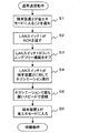
図11は、通常通信動作をしている状態から省エネ状態に以降する動作の一例をフローチャートで示したものである。端末装置2が省エネ状態になることを通知(ステップS1)した後、LANスイッチ1からそれに対する応答(ACK)が返される(ステップS2)。 FIG. 11 is a flowchart showing an example of an operation for changing from the state of normal communication operation to the energy saving state. After notifying that the terminal device 2 is in the energy saving state (step S1), a response (ACK) to the LAN switch 1 is returned (step S2).
LANスイッチ1は、応答と同時にスパニングツリー機能をオフし(ステップS3)、その後の接続状態の変化に対する機器情報収集パケットをネットワーク上に流さないようにする。そうすることで頻繁に接続状態が変化することによるネットワークトラフィックの増加を防ぐ。 The LAN switch 1 turns off the spanning tree function at the same time as the response (step S3), and prevents a device information collection packet for subsequent changes in the connection state from flowing on the network. This prevents an increase in network traffic due to frequent connection changes.
その後、消費電力低減を目的にリンク速度(ネットワーク接続スピード)を落とすため、お互いにネゴシエーションを実施し(ステップS4)、最も遅い、若しくは最も消費電力が低いスピードに設定する(ステップS5)。 Thereafter, in order to reduce the link speed (network connection speed) for the purpose of reducing power consumption, negotiations are performed with each other (step S4), and the slowest or the lowest power consumption is set (step S5).
その後、端末装置2はCPU、ROM、RAM等のモジュールの電源をオフすることで省エネ状態に入る(ステップS6)。 Thereafter, the terminal device 2 enters an energy saving state by turning off the power of modules such as the CPU, ROM, and RAM (step S6).
省エネ状態の端末宛のパケットが来ない限り、またはユーザ操作による端末装置2の省エネ状態解除が無い限り、そのまま省エネ状態を保持する(待機動作)。 As long as there is no packet addressed to the terminal in the energy saving state or there is no cancellation of the energy saving state of the terminal device 2 by the user operation, the energy saving state is maintained as it is (standby operation).
この時、端末装置2として複合機(MFP)やプリンタ等が接続されていると、ホストPCから定期的な状態管理情報の送信要求が行われる可能性がある。端末装置2は、このような状態管理情報の送信要求に応答する必要があるが、省エネ状態であるとCPUが応答することが出来ない。また、定期的な送信要求の度にWakeしていては、消費電力削減の効果が薄れる。 At this time, if a multifunction peripheral (MFP), a printer, or the like is connected as the terminal device 2, there is a possibility that a periodic status management information transmission request may be made from the host PC. The terminal device 2 needs to respond to such a transmission request for state management information, but the CPU cannot respond if it is in the energy saving state. In addition, the effect of reducing power consumption is diminished if wakening is performed for each periodic transmission request.
そこで、本実施形態では、端末装置2が省エネ状態に入る前に、端末装置2のステータス情報をLANスイッチ1で保持することが考えられる。 Therefore, in this embodiment, it is conceivable that the status information of the terminal device 2 is held by the LAN switch 1 before the terminal device 2 enters the energy saving state.
端末装置2は省エネ状態になる前に、その時点での自身のステータス情報をLANスイッチ1に送信し、LANスイッチ1はそのデータ(ステータス情報)を自身のRAM203に保持しておく。
Before the terminal device 2 enters the energy saving state, the terminal device 2 transmits its own status information to the LAN switch 1, and the LAN switch 1 holds the data (status information) in its
省エネ状態移行後、ホストPCから状態情報要求が来た場合は、LANスイッチ1が保持しているデータ(ステータス情報)を要求元(ホストPC)に送信する。LANスイッチ1は状態情報(ステータス情報)と端末装置を認識できるID(MACアドレスやIPアドレス等)とを紐付けして保持することにより、上述の動作が可能になる。 When a status information request is received from the host PC after shifting to the energy saving state, the data (status information) held by the LAN switch 1 is transmitted to the request source (host PC). The LAN switch 1 can perform the above-described operation by associating and holding state information (status information) and an ID (such as a MAC address or an IP address) that can recognize the terminal device.
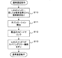
図12は、省エネ状態から通常通信状態に復帰する場合の動作をフローチャートに示したものである。復帰要求があると(ステップS10)、再度ネゴシエーションを開始するが(ステップS11)、このネゴシエーションでは最速のネットワークスピードで接続され(ステップS12)、LANスイッチ1はスパニングツリー機能をオンし(ステップS13)、通常通信動作に戻る。 FIG. 12 is a flowchart showing the operation when returning from the energy saving state to the normal communication state. When there is a return request (step S10), the negotiation is started again (step S11). In this negotiation, connection is made at the fastest network speed (step S12), and the LAN switch 1 turns on the spanning tree function (step S13). Return to normal communication operation.
以上説明したように、本実施形態によれば、ネットワーク接続機能を搭載した端末装置が省エネ状態に入る際にネットワークスピードを再設定するためのネゴシエーション機能を備えることで、ユーザの手を煩わせることなく、消費電力低減を目的とした最適なスピードに設定できる。 As described above, according to the present embodiment, the terminal device equipped with the network connection function is provided with the negotiation function for resetting the network speed when entering the energy saving state, thereby bothering the user. And can be set to an optimal speed for the purpose of reducing power consumption.
上記ネゴシエーション機能は、ネットワーク機器(ネットワーク接続機能を搭載した端末装置)に実装されている物理層デバイス(PHY)で設定可能な最も電力の少ないスピードで接続することで、ネットワーク系の消費電力低減も可能となる。 The above-mentioned negotiation function reduces the power consumption of the network system by connecting at the speed with the least power that can be set by the physical layer device (PHY) installed in the network equipment (terminal equipment equipped with the network connection function). It becomes possible.
上記ネゴシエーション機能は、ネットワーク機器と接続相手側のネゴシエーションの結果、最も遅いスピードで接続するため、最も早いスピードでの接続に比較して消費電力低減が可能となる。 Since the negotiation function is connected at the slowest speed as a result of the negotiation between the network device and the connection partner, power consumption can be reduced compared to the connection at the fastest speed.
ネットワーク機器に接続されている接続相手側のLANスイッチは、ネットワーク機器が省エネ状態に入る旨の通知を受けると、そのLANスイッチが持っているスパニングツリー機能を無効にすることにより、ネットワーク機器が省エネ状態になる都度スパニングツリーを機能させることによるネットワークトラフィックの増大を防ぐことができる。 When a LAN switch connected to a network device receives a notification that the network device is in an energy saving state, it disables the spanning tree function of the LAN switch, thereby saving the network device. It is possible to prevent an increase in network traffic due to the functioning of the spanning tree each time it enters a state.
LANスイッチは、接続されているネットワーク機器が省エネ状態に入る前に、当該ネットワーク機器のステータス情報を予め取得することにより、ネットワーク機器が省エネモードを維持することができ、省エネ効果が大きくなる。 The LAN switch acquires the status information of the network device in advance before the connected network device enters the energy saving state, whereby the network device can maintain the energy saving mode, and the energy saving effect is increased.
ネットワークに接続されている他のネットワーク機器から、省エネ状態のネットワーク機器のステータス情報を要求された場合に、LANスイッチが予め取得しておいた上記ネットワーク機器のステータス情報を返すことにより、ネットワーク機器が省エネモードを維持でき、省エネ効果が大きくなる。 When other network devices connected to the network request the status information of the energy-saving network device, the network device returns the status information of the network device previously acquired by the LAN switch. The energy saving mode can be maintained, and the energy saving effect is increased.
なお、各図のフローチャートに示す処理を、CPUが実行するためのプログラムは本発明によるプログラムを構成する。このプログラムを記録する記録媒体としては、半導体記憶部や光学的及び/又は磁気的な記憶部等を用いることができる。このようなプログラム及び記録媒体を、前述した各実施形態とは異なる構成のシステム等で用い、そこのCPUで上記プログラムを実行させることにより、本発明と実質的に同じ効果を得ることができる。 Note that the program for the CPU to execute the processing shown in the flowcharts of the drawings constitutes a program according to the present invention. As a recording medium for recording the program, a semiconductor storage unit, an optical and / or magnetic storage unit, or the like can be used. By using such a program and a recording medium in a system having a configuration different from that of each of the above-described embodiments and causing the CPU to execute the program, substantially the same effect as the present invention can be obtained.
以上、本発明を好適な実施形態に基づき具体的に説明したが、本発明は上記のものに限定されるものではなく、その要旨を逸脱しない範囲で種々変更可能であることは言うまでもない。 Although the present invention has been specifically described above based on the preferred embodiments, it is needless to say that the present invention is not limited to the above-described ones and can be variously modified without departing from the gist thereof.
1A〜1D LANスイッチ
2A〜2H 端末装置
3 基幹ネットワーク
100、203 RAN
101、204 ROM
102、202 CPU
103、201 MAC
104、200 PHY
1A to
101, 204 ROM
102, 202 CPU
103, 201 MAC
104, 200 PHY
Claims (13)
前記端末装置は、
省エネ状態に以降する時に、前記ネットワーク制御装置と接続するネットワークのスピードを再設定するスピード設定手段を備えることを特徴とするネットワークの接続システム。 A network connection system including a plurality of network control devices connected to a terminal device having a network connection function,
The terminal device
A network connection system comprising speed setting means for resetting a speed of a network connected to the network control device when the energy saving state is set.
前記端末装置から、前記端末装置が省エネ状態に入る旨の通知を受けた場合は、前記ネットワーク制御装置が有するスパニングツリー機能を無効にすることを特徴とする請求項1から3のいずれか1項記載のネットワークの接続システム。 The network controller is
4. The spanning tree function of the network control device is invalidated when receiving a notification from the terminal device that the terminal device enters an energy saving state. 5. The network connection system described.
前記端末装置が省エネ状態に入る前に前記端末装置から送信された前記端末装置のステータス情報を、記憶部に記憶することを特徴とする請求項1から4のいずれか1項記載のネットワークの接続システム。 The network controller is
5. The network connection according to claim 1, wherein status information of the terminal device transmitted from the terminal device before the terminal device enters an energy saving state is stored in a storage unit. system.
ネットワークに接続する他の装置から、省エネ状態の前記端末装置のステータス情報を要求された場合は、前記記憶部に記憶したステータス情報を返すことを特徴とする請求項5記載のネットワークの接続システム。 The network controller is
6. The network connection system according to claim 5, wherein when the status information of the terminal device in the energy saving state is requested from another device connected to the network, the status information stored in the storage unit is returned.
省エネ状態に以降する時に、前記ネットワーク制御装置と接続するネットワークのスピードを再設定するスピード設定手段を備えることを特徴とする端末装置。 The terminal device of the network connection system comprising a plurality of network control devices connected to a terminal device having a network connection function,
A terminal device comprising speed setting means for resetting a speed of a network connected to the network control device when the energy saving state is set.
前記端末装置から、前記端末装置が省エネ状態に入る旨の通知を受けた場合は、前記ネットワーク制御装置が有するスパニングツリー機能を無効にすることを特徴とするネットワーク制御装置。 The network control device of a network connection system comprising a plurality of network control devices connected to a terminal device having a network connection function,
A network control device characterized by invalidating a spanning tree function of the network control device when the terminal device receives a notification that the terminal device enters an energy saving state.
前記端末装置は、
省エネ状態に以降する時に、前記ネットワーク制御装置と接続するネットワークのスピードを再設定するステップを備えることを特徴とするネットワークの接続方法。 A network connection method comprising a plurality of network control devices connected to a terminal device having a network connection function,
The terminal device
A network connection method comprising a step of resetting a speed of a network connected to the network control device when the energy saving state is set.
前記端末装置から、前記端末装置が省エネ状態に入る旨の通知を受けた場合は、前記ネットワーク制御装置が有するスパニングツリー機能を無効にするステップを備えることを特徴とする請求項9記載のネットワークの接続方法。 The network controller is
The network of claim 9, further comprising a step of invalidating a spanning tree function of the network control device when the terminal device receives a notification that the terminal device enters an energy saving state. Connection method.
前記端末装置は、
省エネ状態に以降する時に、前記ネットワーク制御装置と接続するネットワークのスピードを再設定する処理を、前記端末装置であるコンピュータに実行させることを特徴とするネットワークの接続プログラム。 A network connection program comprising a plurality of network control devices connected to a terminal device having a network connection function,
The terminal device
A network connection program for causing a computer, which is the terminal device, to execute processing for resetting the speed of a network connected to the network control device when going into an energy saving state.
前記端末装置から、前記端末装置が省エネ状態に入る旨の通知を受けた場合は、前記ネットワーク制御装置が有するスパニングツリー機能を無効にする処理を、前記ネットワーク制御装置であるコンピュータに実行させることを特徴とする請求項11記載のネットワークの接続プログラム。 The network controller is
When receiving a notification from the terminal device that the terminal device enters an energy saving state, causing the computer that is the network control device to execute processing for invalidating the spanning tree function of the network control device. The network connection program according to claim 11, wherein:
Priority Applications (1)
| Application Number | Priority Date | Filing Date | Title |
|---|---|---|---|
| JP2009281840A JP2011123738A (en) | 2009-12-11 | 2009-12-11 | Connection system of network, terminal unit, network control unit, method of connecting network, program and recording medium |
Applications Claiming Priority (1)
| Application Number | Priority Date | Filing Date | Title |
|---|---|---|---|
| JP2009281840A JP2011123738A (en) | 2009-12-11 | 2009-12-11 | Connection system of network, terminal unit, network control unit, method of connecting network, program and recording medium |
Publications (1)
| Publication Number | Publication Date |
|---|---|
| JP2011123738A true JP2011123738A (en) | 2011-06-23 |
Family
ID=44287559
Family Applications (1)
| Application Number | Title | Priority Date | Filing Date |
|---|---|---|---|
| JP2009281840A Withdrawn JP2011123738A (en) | 2009-12-11 | 2009-12-11 | Connection system of network, terminal unit, network control unit, method of connecting network, program and recording medium |
Country Status (1)
| Country | Link |
|---|---|
| JP (1) | JP2011123738A (en) |
Cited By (2)
| Publication number | Priority date | Publication date | Assignee | Title |
|---|---|---|---|---|
| JP2016213703A (en) * | 2015-05-11 | 2016-12-15 | キヤノン株式会社 | Image forming apparatus, control method therefor, and program |
| US12457131B2 (en) | 2020-09-07 | 2025-10-28 | Kyocera Document Solutions, Inc. | Electronic apparatus |
-
2009
- 2009-12-11 JP JP2009281840A patent/JP2011123738A/en not_active Withdrawn
Cited By (3)
| Publication number | Priority date | Publication date | Assignee | Title |
|---|---|---|---|---|
| JP2016213703A (en) * | 2015-05-11 | 2016-12-15 | キヤノン株式会社 | Image forming apparatus, control method therefor, and program |
| US10257381B2 (en) | 2015-05-11 | 2019-04-09 | Canon Kabushiki Kaisha | Image forming apparatus capable of being set to power saving mode, method of controlling the same, and storage medium |
| US12457131B2 (en) | 2020-09-07 | 2025-10-28 | Kyocera Document Solutions, Inc. | Electronic apparatus |
Similar Documents
| Publication | Publication Date | Title |
|---|---|---|
| JP5350534B2 (en) | Energy efficient Ethernet network nodes and methods of using Ethernet network nodes | |
| JP5300553B2 (en) | COMMUNICATION DEVICE, COMMUNICATION DEVICE CONTROL METHOD, PROGRAM | |
| US8732497B2 (en) | Data processing apparatus, method for controlling data processing apparatus, and storage medium storing program | |
| TW201114222A (en) | Method and system for end-to-end management of energy efficient networking protocols | |
| CN102291293B (en) | Communication device | |
| US20250106139A1 (en) | Link power management protocol for connected network devices | |
| JP2012158078A (en) | Communication device | |
| JP5204191B2 (en) | Magic packet frame transmission method and wireless terminal device | |
| KR101569030B1 (en) | Image forming apparatus and network connection method thereof | |
| JP3793123B2 (en) | Network interface device, power control method, computer-readable storage medium, and program | |
| JP3773688B2 (en) | Devices that can be connected to the network | |
| JP5440104B2 (en) | Network system, network control method, LAN switch, and network control program | |
| JP2011123738A (en) | Connection system of network, terminal unit, network control unit, method of connecting network, program and recording medium | |
| JP2013027991A (en) | Image processing apparatus, communication method and communication program using the same | |
| US9063736B2 (en) | Method and apparatus for reducing a link rate of communication device in a pre-standby state upon detecting no traffic for a predetermined time period | |
| JP2011234304A (en) | Network system | |
| JP2009037285A (en) | Network device | |
| JP2006332807A (en) | Network terminal and energy-saving mode setting method thereof, and energy-saving mode setting program | |
| US20130163616A1 (en) | Communication apparatus that can be operated in power-saving mode, method of controlling the apparatus, and storage medium | |
| JP5114300B2 (en) | Network system, network terminal device, and LAN switch | |
| JP5952802B2 (en) | Response system and response method | |
| JP2009282816A (en) | Energy-saving mode transition management system | |
| JP2010183470A (en) | Network connection device, network connection control method, and program | |
| JP2014103439A (en) | Communication device, communication system, communication device control method, and communication device control program | |
| JP2001312337A (en) | Power saving mode control system |
Legal Events
| Date | Code | Title | Description |
|---|---|---|---|
| A300 | Withdrawal of application because of no request for examination |
Free format text: JAPANESE INTERMEDIATE CODE: A300 Effective date: 20130305 |