JP2011121321A - Inkjet recording apparatus and method for adjusting landing position - Google Patents
Inkjet recording apparatus and method for adjusting landing position Download PDFInfo
- Publication number
- JP2011121321A JP2011121321A JP2009282291A JP2009282291A JP2011121321A JP 2011121321 A JP2011121321 A JP 2011121321A JP 2009282291 A JP2009282291 A JP 2009282291A JP 2009282291 A JP2009282291 A JP 2009282291A JP 2011121321 A JP2011121321 A JP 2011121321A
- Authority
- JP
- Japan
- Prior art keywords
- recording
- pattern
- landing position
- deviation
- ink
- Prior art date
- Legal status (The legal status is an assumption and is not a legal conclusion. Google has not performed a legal analysis and makes no representation as to the accuracy of the status listed.)
- Pending
Links
Images


Classifications
-
- B—PERFORMING OPERATIONS; TRANSPORTING
- B41—PRINTING; LINING MACHINES; TYPEWRITERS; STAMPS
- B41J—TYPEWRITERS; SELECTIVE PRINTING MECHANISMS, i.e. MECHANISMS PRINTING OTHERWISE THAN FROM A FORME; CORRECTION OF TYPOGRAPHICAL ERRORS
- B41J29/00—Details of, or accessories for, typewriters or selective printing mechanisms not otherwise provided for
- B41J29/38—Drives, motors, controls or automatic cut-off devices for the entire printing mechanism
- B41J29/393—Devices for controlling or analysing the entire machine ; Controlling or analysing mechanical parameters involving printing of test patterns
-
- B—PERFORMING OPERATIONS; TRANSPORTING
- B41—PRINTING; LINING MACHINES; TYPEWRITERS; STAMPS
- B41J—TYPEWRITERS; SELECTIVE PRINTING MECHANISMS, i.e. MECHANISMS PRINTING OTHERWISE THAN FROM A FORME; CORRECTION OF TYPOGRAPHICAL ERRORS
- B41J2/00—Typewriters or selective printing mechanisms characterised by the printing or marking process for which they are designed
- B41J2/005—Typewriters or selective printing mechanisms characterised by the printing or marking process for which they are designed characterised by bringing liquid or particles selectively into contact with a printing material
- B41J2/01—Ink jet
- B41J2/21—Ink jet for multi-colour printing
- B41J2/2132—Print quality control characterised by dot disposition, e.g. for reducing white stripes or banding
- B41J2/2135—Alignment of dots
Abstract
Description
本発明は、記録ヘッドよりインクを吐出させて記録を行うインクジェット記録装置およびインクジェット記録装置における記録位置調整方法に関する。 The present invention relates to an ink jet recording apparatus that performs recording by discharging ink from a recording head, and a recording position adjusting method in the ink jet recording apparatus.
従来から、インクジェット記録装置において記録媒体上のドットの記録される位置(インク滴の着弾位置)のずれを調整する技術が知られている。この着弾位置のずれを調整する技術の1つとして、特許文献1が知られている。特許文献1は、記録ヘッド一体型のインクカートリッジを用いたインクジェット記録装置において、インクカートリッジが着脱された際に、装着されているインクカートリッジの種類に応じて着弾位置の調整を行う項目を設定する技術を開示している。例えば、カラーインク用のインクカートリッジ(以下、カラーカートリッジ)のみが装着されている場合は、カラーカートリッジの位置調整(双方向記録の位置調整等)を行う。また、カラーカートリッジとブラックインク用のインクカートリッジ(以下、ブラックカートリッジ)が装着されている場合は、カラーインクを吐出する記録ヘッドとブラックを吐出する記録ヘッド間の位置調整、各カートリッジの位置調整を行う。
2. Description of the Related Art Conventionally, a technique for adjusting a shift of a dot recording position (ink droplet landing position) on a recording medium in an ink jet recording apparatus is known.
特許文献1の技術では、装着されているインクカートリッジ(記録ヘッド)の種類に応じて位置調整を行う項目を設定しているため、インクカートリッジの着脱の際に、調整の必要のない項目についても位置調整が実行されるようになっていた。例えば、カラーカートリッジとブラックカートリッジが装着されている状態で、カラーカートリッジが着脱されたとすると、カラーインクを吐出する記録ヘッドとブラックを吐出する記録ヘッド間の位置調整、各カートリッジの吐出位置調整を行う。しかし、この場合、ブラックカートリッジは着脱されていないので、ブラックインクを吐出する記録ヘッドの位置調整(双方向記録の位置調整等)は本来、行う必要が無い。
In the technique of
このように、装着されているインクカートリッジ(記録ヘッド)の種類に応じて着弾位置の調整を行う項目を設定すると、調整の必要のない項目についても位置調整が実行される問題があった。 As described above, when the item for adjusting the landing position is set according to the type of the mounted ink cartridge (recording head), there is a problem that the position adjustment is executed even for an item that does not need to be adjusted.
本発明は、独立に着脱可能な複数の記録ヘッドを用い、前記複数の記録ヘッドからインクを吐出することにより画像を記録するインクジェット記録装置であって、前記複数の記録ヘッドそれぞれの着脱を検出する検出手段と、前記複数の記録ヘッド単独の着弾位置のずれおよび前記複数の記録ヘッドのうちの2つの記録ヘッド間の着弾位置のずれを調整するためのパターンを記録するパターン記録手段とを有し、前記パターン記録手段は、着脱された前記記録ヘッド単独の着弾位置のずれおよび着脱された前記記録ヘッドを含む記録ヘッド間の着弾位置のずれを調整するためのパターンのみを記録することを特徴とする。 The present invention is an ink jet recording apparatus that uses a plurality of independently detachable recording heads to record an image by ejecting ink from the plurality of recording heads, and detects attachment / detachment of each of the plurality of recording heads. Detecting means; and pattern recording means for recording a pattern for adjusting deviation of landing positions of the plurality of recording heads alone and landing position deviation between two recording heads of the plurality of recording heads. The pattern recording means records only a pattern for adjusting the deviation of the landing position of the detachable recording head alone and the deviation of the landing position between the recording heads including the detachable recording head. To do.
本発明によれば、インクカートリッジが着脱された際に、調整の必要のない項目の位置調整を実行しないようにすることができる。 According to the present invention, it is possible to prevent the position adjustment of items that do not need to be adjusted when the ink cartridge is attached or detached.
[インクジェット記録装置の制御構成]
図1は、本発明を適用可能なインクジェット記録装置の制御構成を示すブロック図である。パターン記憶メモリ101は、記録ヘッドから吐出されるインクの着弾位置を調整するための基準パターンおよび調整パターンを記憶しておくメモリである。インクジェット記録装置100(以下、記録装置)に内蔵され、不揮発性メモリ(ROM)で構成されている。なお、パターン記憶メモリ101は記録装置本体ではなくコンピュータなどの外部装置に備わっていても良い。その場合は、インターフェース107を介してパターン記憶メモリ101に記憶した調整パターンを転送することも可能である。
[Control configuration of inkjet recording apparatus]
FIG. 1 is a block diagram showing a control configuration of an ink jet recording apparatus to which the present invention can be applied. The
調整値記憶メモリ102は、着弾位置の調整した結果を記憶しておくメモリである。記録装置本体に内蔵され、書き換え可能な不揮発性メモリ(EEPROM)で構成されている。また、調整値記憶メモリ102は、パターン記憶メモリ101と同様に外部装置に備わっていても良い。通常のユーザが所望の画像を記録する場合は、この調整値記憶メモリ102に記憶された調整値を用いて記録を行う。
The adjustment
パターン展開バッファ103は、パターン記憶メモリ101に記憶されたパターンを記録のために一時的に記憶保持する記録装置本体に内蔵された揮発性メモリ(RAM)である。制御装置104は、演算処理、各装置間の連携、記録装置全体の制御を司る記録装置本体に内蔵された装置であり、CPUやMPUに相当する。
The
パターン読取装置105は、記録装置に搭載した発光体と受光体で構成された光学系のセンサである。記録媒体に記録されたパターンの濃度を電気的信号に変換して読み取るために用いる。記録ヘッド106は、インクジェット方式に代表されるインクを記録媒体に吐出する装置である。記録ヘッド106は、パターン記憶メモリ101からパターン展開バッファ103に展開されたパターンを制御装置104の指示により記録する装置である。また、この記録ヘッド106は、パターン展開バッファ103展開されたパターンをパターン記録する際、制御装置104は調整値記憶メモリ102に記憶された調整値に基づいてインクの吐出タイミングを変化させ、インク滴の着弾位置を調整することができる。
The
インターフェース107は、コンピュータ、ディジタルカメラに代表される外部装置からの記録データおよび制御コマンドの受信および送信を行う装置である。インクカートリッジ着脱検出部108は、
記録ヘッドとインクタンクとが一体に構成されたインクカートリッジの着脱状態を検出する装置であり、インクカートリッジとキャリッジとの電気的接続に基づいてインクカートリッジが着脱されたことを検出できるようになっている。その際、インクカートリッジ着脱検出部108は着脱が行われたインクカートリッジも検出する。図1に図示していないが、本実施形態のインクジェット記録装置は、記録媒体の給紙機構、紙送り機構、排紙機構、インクタンクおよび記録ヘッド106を搭載したキャリッジを駆動する電源を含んでいる。
The
This is a device for detecting the attachment / detachment state of an ink cartridge in which a recording head and an ink tank are integrated, and can detect that an ink cartridge has been attached / detached based on an electrical connection between the ink cartridge and a carriage. Yes. At that time, the ink cartridge attachment / detachment detection unit 108 also detects the ink cartridge that has been attached / detached. Although not shown in FIG. 1, the ink jet recording apparatus according to the present embodiment includes a power supply that drives a carriage on which a recording medium feed mechanism, a paper feed mechanism, a paper discharge mechanism, an ink tank, and a
[インクジェット記録装置の構成]
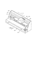
図2は、本発明を適用可能なインクジェット記録装置の外観斜視図である。記録装置100の給紙位置に挿入された記録媒体206は、送りローラ202によってインクカートリッジ203〜205の記録可能領域へ搬送される。キャリッジ201は、2つのガイド軸207および208によって定められたX方向に移動可能な構成となっており、記録領域を往復走査する。キャリッジ201には、シアン、マゼンタ、イエローの各色について、インクを供給するインクタンクとそのインクを吐出する記録ヘッドとが一体に構成された一体型のインクカートリッジ203〜205が搭載されている。
[Configuration of Inkjet Recording Apparatus]
FIG. 2 is an external perspective view of an ink jet recording apparatus to which the present invention can be applied. The
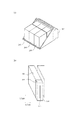
図3は、インクカートリッジの構成を説明する図である。図3(A)に図示するように、シアンインク用のインクカートリッジ203、マゼンタインク用のインクカートリッジ204、イエローインク用のインクカートリッジ205が、キャリッジ201に対してそれぞれ独立に着脱可能な構成となっている。同図(B)はインクカートリッジの構成を示しており、各色のインクカートリッジ203〜205の構成はこれに同じである。インクカートリッジは、インクを収容するインクタンク209と、インクを吐出する記録ヘッド106とにより構成される。記録ヘッド106の吐出口面210には、走査方向Xと直交するY方向にインクを吐出するためのノズル(吐出口)が配列されたノズル列(吐出口列)211が形成されている。更に、ノズル列(吐出口列)211は、奇数列と偶数列とに分かれており、この2列は互いにノズルピッチの半分だけY方向にずれた構成となっている。
FIG. 3 is a diagram illustrating the configuration of the ink cartridge. As shown in FIG. 3A, the
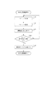
次に、図4を用いて、本実施形態における着弾位置ずれの調整の手順について説明する。まず、ステップS401において、着弾位置ずれを調整するためのパターンを記録媒体上に記録する。そして、ステップS402で、パターン読取装置105を用いて複数のパターンそれぞれの光学濃度を測定する。ステップS402により測定したパターンの光学濃度は一時的に保持し、ステップS403における調整値の算出(取得)の工程に用いる。
Next, the procedure for adjusting the landing position deviation in the present embodiment will be described with reference to FIG. First, in step S401, a pattern for adjusting landing position deviation is recorded on a recording medium. In step S402, the
ステップS404で、全調整項目について調整値の取得が完了したか否かを判断する。なお、本実施形態では、新たに装着されたインクカートリッジの組み合わせにより、実行する調整項目が異なっている。この詳細については後述する。 In step S404, it is determined whether or not acquisition of adjustment values has been completed for all adjustment items. In the present embodiment, the adjustment items to be executed differ depending on the combination of newly installed ink cartridges. Details of this will be described later.
ステップS404において、全調整項目の調整値取得が完了したと判断されれば、ステップS405により調整値記憶メモリ102に各調整項目の調整値を記憶し、以後の記録時には調整値に基づいて吐出タイミングが変更される。また、ステップS404において、全調整項目について調整値の取得が完了していないと判断されれば、ステップS401に戻り、調整値の取得が完了していない調整個目についてパターンの記録、光学濃度の読み取りを行って、調整値を取得する。
If it is determined in step S404 that the adjustment value acquisition for all the adjustment items has been completed, the adjustment value of each adjustment item is stored in the adjustment
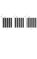
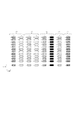
図5は、上述のS401において記録媒体上に記録されるパターンを説明する図である。 FIG. 5 is a diagram illustrating the pattern recorded on the recording medium in S401 described above.
ここでは、双方向記録を行う際、あるノズル列について、往方向記録における着弾位置と復方向記録における着弾位置との調整する場合を例に説明する。詳しくは後述するが、本実施形態では、1つの基準パターンと複数の調整パターンとを記録し、基準パターンの光学反射濃度に最も近い光学反射濃度を有する調整パターンを検出し、この調整パターンを記録したときのインク吐出タイミングを調整値として取得する。 Here, a case will be described as an example in which the landing position in forward recording and the landing position in backward recording are adjusted for a certain nozzle row when performing bidirectional recording. As will be described in detail later, in this embodiment, one reference pattern and a plurality of adjustment patterns are recorded, an adjustment pattern having an optical reflection density closest to the optical reflection density of the reference pattern is detected, and this adjustment pattern is recorded. The ink ejection timing at this time is acquired as an adjustment value.
まず、図5(A)は基準パターンのドット配置を模式的に示した図である。「R」で示される基準パターンにおいて、基準ドット501と基準ドット502は共に同じ走査方向(往方向または復方向)で記録される。詰まり、基準パターンにおいては、往方向記録の着弾位置と復方向記録の着弾位置のずれの影響を受けることなく、理想的なドット配置のパターンとして記録される。ここでは、基準ドット501と基準ドット502が重ならないドット配置を理想的なドット配置としているが、基準ドット501と基準ドット502が完全に重なるドット配置を理想的なドット配置としてもよい。
First, FIG. 5A schematically shows the dot arrangement of the reference pattern. In the reference pattern indicated by “R”, both the
図5(B)、(C)は調整パターンのドット配置を模式的に示した図である。図5(B)は、往方向(右方向,+X方向)で記録される基準ドット501に対して、復方向(左方向,−X方向)で記録される調整ドット503を「+1」だけずらした、ずらし量が「+1」のパターンとなっている。ここで、ずらし量について説明すると、ずらし量は、基準ドットに対して調整ドットの着弾位置を記録ヘッドの走査進行方向にずらす場合を「+」、走査進行方向とは逆方向にずらす場合を「−」として表現する。また、本実施形態の記録装置では、調整ドットの着弾位置を4800dpi単位でずらすことが可能であり、「1」、「2」で表されるずらし量の大きさは、1/4800inch、2/4800inchとなっている。つまり、「+1」で表されるずらし量は、基準ドット501に対して調整ドット503を復方向の進行方向(−X方向)に1/4800inchずらしていることになる。図5(C)は、往方向で記録される基準ドット501に対して、復方向で記録される調整ドット503を「−1」だけずらした、ずらし量が「−1」のパターンとなっている。
5B and 5C are diagrams schematically showing the dot arrangement of the adjustment pattern. In FIG. 5B, the
ここで、往方向記録の着弾位置と復方向記録の着弾位置にずれが生じていいなければ、ずれ量「+1」のパターン、ずれ量「−1」のパターンは、図5(B)、(C)に示されるように理想的なドット配置からずれて記録されることになる。仮に、ずらし量「+1」の調整パターンが基準パターンと同じ理想的なドット配置となった場合には、往方向記録の着弾位置に対して復方向記録の着弾位置が相対的に「−1」だけずれていることが検出できる。そこで、本実施形態では、後述するようにずらし量「+5」から「−5」まで異ならせて調整パターンを複数記録し、基準パターンのドット配置に近い調整パターンを検出する。そして、その調整パターンを記録したときのずらし量を調整値として取得して、この調整値に基づいて実記録時に着弾位置を調整するようにしている。 Here, if there is no deviation between the landing position of the forward direction recording and the landing position of the backward direction recording, the pattern of the deviation amount “+1” and the pattern of the deviation amount “−1” are shown in FIGS. As shown in (C), recording is performed while deviating from the ideal dot arrangement. If the adjustment pattern with the shift amount “+1” has the same ideal dot arrangement as the reference pattern, the landing position of the backward recording is relatively “−1” with respect to the landing position of the forward recording. It is possible to detect that it is shifted by only. Therefore, in this embodiment, as will be described later, a plurality of adjustment patterns are recorded with different amounts of shift from “+5” to “−5”, and an adjustment pattern close to the dot arrangement of the reference pattern is detected. Then, the shift amount when the adjustment pattern is recorded is acquired as an adjustment value, and the landing position is adjusted during actual recording based on the adjustment value.
次に、基準パターンのドット配置に近い調整パターンを検出するために、ステップS402では、パターン読取装置105を用いて記録した複数のパターンの光学濃度を測定する。パターンの反射光学濃度はドットの重なり具合と相関しており、基準パターンの反射光学濃度に最も近い反射光学濃度の調整パターンを選択することで、基準パターンのドット配置に近い調整パターンを検出することができる。なお、各パターンの濃度測定は、比較的広範囲の領域における平均濃度を測定し、これを各パターンの濃度として取得する方法が好適である。
Next, in order to detect an adjustment pattern close to the dot arrangement of the reference pattern, in step S402, the optical density of a plurality of patterns recorded using the
以上では、双方向記録時の往方向記録と復方向記録の着弾位置のずれの調整の場合を例に示したが、異色のノズル列同士の走査方向の着弾位置のずれや、同色の奇数列と偶数列の着弾位置のずれにも適用できる。例えば、シアンのノズル列とマゼンタのノズル列の着弾位置のずれを調整する場合、基準パターンの基準ドット501,502をシアンノズル列で記録し、調整パターンの基準ドットをシアンノズル列、調整ドットをマゼンタノズル列で記録する。同色の奇数列と偶数列の着弾位置のずれの場合は、例えば、基準パターンの基準ドット501,502を奇数列で記録し、調整パターンの基準ドットを奇数列、調整ドットを偶数列で記録する。
In the above, an example of adjusting the deviation of the landing position between the forward direction recording and the backward direction recording during bidirectional recording has been shown as an example, but the deviation of the landing position in the scanning direction between the nozzle rows of different colors or the odd number of rows of the same color It can also be applied to the deviation of landing positions in even-numbered rows. For example, when adjusting the displacement of the landing positions of the cyan nozzle row and the magenta nozzle row, the
図6は、記録媒体206に記録されるパターンの標準的なレイアウトを示す。601で示されるパターンは、シアンカートリッジ203に係る着弾位置調整のパターンであり、列Aがシアンノズル列の双方向記録時の着弾位置調整のパターン、列Bがシアンノズル列の奇数列と偶数列の着弾位置調整のパターンである。602で示されるパターンは、マゼンタカートリッジ204に係る着弾位置調整のパターンであり、列Cがマゼンタノズル列の双方向記録時の着弾位置調整のパターン、列Dがマゼンタノズル列の奇数列と偶数列の着弾位置調整のパターンである。603で示されるパターンは、イエローカートリッジ205に係る着弾位置調整のパターンであり、列Eがイエローノズル列の双方向記録時の着弾位置調整のパターン、列Fがイエローノズル列の奇数列と偶数列の着弾位置調整のパターンである。
FIG. 6 shows a standard layout of a pattern recorded on the
604で示されるパターンは、シアンカートリッジ203とマゼンタカートリッジ204との着弾位置調整のパターンであり、列Gはシアンノズル列とマゼンタノズル列の走査方向の着弾位置調整のパターンである。605で示されるパターンは、マゼンタカートリッジ204とイエローカートリッジ205との着弾位置調整のパターンであり、列Hはマゼンタノズル列とイエローノズル列の走査方向の着弾位置調整のパターンである。
A pattern indicated by 604 is a pattern for adjusting the landing positions of the
ここで、本実施形態では、異色のノズル列間(記録ヘッド間)の着弾位置調整を相対的な位置調整管理としている。詰まり、本実施形態では、隣接するノズル列間の位置調整値のみを取得するようにしており、その他のノズル列間の位置調整では、上記位置調整値を組み合わせて着弾位置を調整する。具体的には、隣接するノズル列間の位置調整値として、シアンノズル列とマゼンタノズル列間の位置調整値(列G)と、マゼンタノズル列とイエローノズル列間の位置調整値(列H)とを取得する。そして、シアンノズル列とイエローノズル列間の位置調整は2つの調整値の足し合わせにより行う。このような相対管理により、多数のノズル列間の位置調整を行う場合でも必要な調整値を少なくすることができ、メモリの記憶容量の低減につながる。 Here, in the present embodiment, landing position adjustment between nozzle rows of different colors (between recording heads) is used as relative position adjustment management. In this embodiment, only the position adjustment value between adjacent nozzle rows is acquired, and in the position adjustment between other nozzle rows, the landing position is adjusted by combining the position adjustment values. Specifically, as a position adjustment value between adjacent nozzle rows, a position adjustment value between the cyan nozzle row and the magenta nozzle row (row G), and a position adjustment value between the magenta nozzle row and the yellow nozzle row (row H). And get. The position adjustment between the cyan nozzle row and the yellow nozzle row is performed by adding two adjustment values. By such relative management, even when the position adjustment between a large number of nozzle rows is performed, the necessary adjustment value can be reduced, leading to a reduction in the storage capacity of the memory.
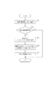
図7は、インクカートリッジの着脱がなされた際の処理フローを示す。この処理フローは、例えば、インクカートリッジ着脱検出部108がインクカートリッジの着脱を検出したタイミングをトリガーに開始される。インクカートリッジ着脱検出部108によってインクカートリッジの着脱が検出されると、S701で着弾位置調整を実行するかをユーザに確認する。その方法としては、例えば、記録装置に接続されたホストPCのモニタに着弾位置調整を実施するか否かのメッセージを表示し、ユーザがマウス、キーボードの操作により着弾位置調整を実施するかの指示をする方法等がある。また、インクカートリッジが着脱された際には自動的に着弾位置調整を実行するように構成してもよい。 FIG. 7 shows a processing flow when the ink cartridge is attached and detached. This processing flow is started, for example, at a timing when the ink cartridge attachment / detachment detection unit 108 detects the attachment / detachment of the ink cartridge. When the ink cartridge attachment / detachment detection unit 108 detects the attachment / detachment of the ink cartridge, it confirms with the user whether or not the landing position adjustment is executed in S701. As the method, for example, a message indicating whether or not to perform landing position adjustment is displayed on the monitor of the host PC connected to the recording apparatus, and an instruction whether or not the user performs landing position adjustment by operating the mouse and the keyboard There are ways to do this. The landing position adjustment may be automatically executed when the ink cartridge is attached or detached.
S702において、着弾位置調整を実行することが指示されていることが確認されると、S703へと進み、着脱されたインクカートリッジに関する情報を取得する。次に、S704では、調整項目決定テーブルを参照し、着脱されたインクカートリッジの情報に基づいて位置調整を実行する調整項目を決定する。 If it is confirmed in S702 that execution of landing position adjustment has been instructed, the process proceeds to S703, and information regarding the detached ink cartridge is acquired. In step S <b> 704, the adjustment item determination table is referred to, and an adjustment item for performing position adjustment is determined based on the information of the attached and detached ink cartridges.
図8は、S704で用いられる調整項目決定テーブルを示す。この調整項目決定テーブルは、記録装置本体の不揮発性メモリ(ROM)に格納されて、制御装置104により読み出されるようになっており、パターン記憶メモリ101や調整値記憶メモリ102と同一のメモリ内に格納されていてもよい。図8に示すように、本実施形態では、着脱されたインクカートリッジに関係のある調整項目のパターンのみを記録し、その着弾位置調整値を取得するようにしている。
FIG. 8 shows an adjustment item determination table used in S704. This adjustment item determination table is stored in a non-volatile memory (ROM) of the recording apparatus main body, and is read by the control device 104. The adjustment item determination table is stored in the same memory as the
例えば、シアンカートリッジのみが着脱された際には、シアンノズル列に係る調整項目、すなわちシアンノズル列の双方向記録時の調整、シアンノズル列の奇数列と偶数列間の調整、シアンノズル列とマゼンタノズル列間の調整を行うようにする。また、マゼンタカートリッジとイエローカットリッジに関しては何ら着脱の操作が行われておらず、これらの着弾位置のずれが変ることはないので、これらの調整については実行しない。 For example, when only the cyan cartridge is attached or detached, adjustment items related to the cyan nozzle row, i.e., adjustment during bidirectional printing of the cyan nozzle row, adjustment between the odd and even rows of the cyan nozzle row, Make adjustments between the magenta nozzle rows. In addition, no attachment / detachment operation is performed on the magenta cartridge and the yellow cut ridge, and the shift of the landing positions does not change, so that these adjustments are not executed.
調整項目が決定されると、続いてS705で図4に示す着弾位置調整を行う。図4のフローに従えば、S404では決定された調整項目の全てが完了するまでパターンの記録、読み取り等の処理を行う。なお、パターンの記録においては、図7に示したレイアウトを維持したまま調整の必要ないパターンを記録しないようにしてもよいし、必要のないパターンのスペースを詰めて記録するようにしてもよい。 When the adjustment item is determined, the landing position adjustment shown in FIG. 4 is performed in S705. According to the flow of FIG. 4, in step S404, processing such as pattern recording and reading is performed until all of the determined adjustment items are completed. In pattern recording, a pattern that does not need to be adjusted may not be recorded while the layout shown in FIG. 7 is maintained, or may be recorded with a space for an unnecessary pattern.
以上のとおり、本実施形態によれば、調整の必要が無い、着脱の行われていない調整の必要のないインクカートリッジの位置調整を実行しないようにすることができる。 As described above, according to the present embodiment, it is possible to prevent the adjustment of the position of an ink cartridge that does not require adjustment and that does not require adjustment that is not attached or detached.
[その他の実施形態]
上記実施形態では、インクカートリッジの着脱を検出する構成としているため、新たに装着されたインクカートリッジが新しいインクカートリッジなのか、1度外されたインクカートリッジが再度装着されたのかまでは検出できなかった。そこで、本実施形態は、新しいインクカートリッジが装着される「交換」と、1度外されたインクカートリッジが再度そのまま装着される「再装着」とを識別できるようにし、それぞれで処理を異ならせるものである。
[Other Embodiments]
In the above embodiment, since it is configured to detect attachment / detachment of an ink cartridge, it was not possible to detect whether a newly installed ink cartridge is a new ink cartridge or whether a once removed ink cartridge is installed again. . Therefore, in the present embodiment, it is possible to identify “replacement” in which a new ink cartridge is mounted and “remount” in which a once removed ink cartridge is mounted again, and processing is different for each. It is.
本実施形態のインクカートリッジは記録ヘッドに個体情報を格納したメモリを備えている。そして、インクカートリッジ着脱検出部108はインクカートリッジの着脱時に、メモリの個体情報を読み取ることでインクカートリッジ(記録ヘッド)が「交換」されたか「再装着」されたかを検出できるようになっている。すなわち、着脱前後でメモリの個体情報が異なっていれば「交換」と判断でき、着脱前後でメモリの個体情報が一致していれば「再装着」と判断できる。そして、「交換」と検出された場合には、上記実施形態と同じように調整項目の決定を行う。 The ink cartridge according to this embodiment includes a memory that stores individual information in a recording head. The ink cartridge attachment / detachment detection unit 108 can detect whether the ink cartridge (recording head) has been “replaced” or “reattached” by reading individual information in the memory when the ink cartridge is attached / detached. That is, if the memory individual information is different before and after the attachment / detachment, it can be determined as “exchange”, and if the memory individual information is the same before and after the attachment / detachment, it can be determined as “reattachment”. When “exchange” is detected, the adjustment item is determined in the same manner as in the above embodiment.
これに対して、「再装着」と検出された場合には、1つのインクカートリッジ単独(記録ヘッド単独)で行う位置調整(双方向、奇数列−偶数列)を行わないようにする。これは、「再装着」の場合にはインクカートリッジ(記録ヘッド)の吐出特性に変更はないので、「再装着」されたインクカートリッジ単独で行う位置調整を省略できるのである。 On the other hand, when “re-installation” is detected, position adjustment (bidirectional, odd-numbered row-even-numbered row) performed by one ink cartridge alone (recording head alone) is not performed. This is because in the case of “remounting”, there is no change in the ejection characteristics of the ink cartridge (recording head), so that the position adjustment performed by the “remounted” ink cartridge alone can be omitted.
例えば、シアンカートリッジのみが「再装着」された際には、シアンノズル列の双方向記録時の調整、シアンノズル列の奇数列と偶数列間の調整は行わず、シアンノズル列とマゼンタノズル列間の調整のみを行うようにする。 For example, when only the cyan cartridge is “re-installed”, the cyan nozzle row and magenta nozzle row are not adjusted during the bi-directional printing of the cyan nozzle row and between the odd and even rows of the cyan nozzle row. Only make adjustments in between.
以上のように、本実施形態によれば、インクカートリッジの「交換」と「再装着」とを識別できるようにし、インクカートリッジが「再装着」された場合には、1つのインクカートリッジ単独で行う調整項目を実行しないようにすることができる。 As described above, according to the present embodiment, it is possible to distinguish between “replacement” and “remounting” of an ink cartridge, and when an ink cartridge is “remounted”, one ink cartridge is used alone. It is possible to prevent adjustment items from being executed.
[その他]
上記実施形態では、シアン、マゼンタ、イエローの3色を備えるインクジェット記録装置を例に説明をしたが、更にブラックや、淡インク、特色インク(レッド、グリーン等)を更に備える記録装置であってもよい。
[Others]
In the above embodiment, an inkjet recording apparatus having three colors of cyan, magenta, and yellow has been described as an example. However, even a recording apparatus further including black, light ink, and special color ink (red, green, etc.). Good.
また、上記実施形態では、1つの基準パターンと複数の調整パターンとを記録し、基準パターンの光学反射濃度に最も近い光学反射濃度を有する調整パターンを検出することで、調整値を取得している。しかし、広く知られているように、ずらし量を異ならせた複数のパターンを記録して、光学反射濃度が最大となるときのずらし量または最小となるときのずらし量を調整値とする方法であってもよく、どのようなパターンから調整値を取得するかは問わない。 In the above embodiment, one reference pattern and a plurality of adjustment patterns are recorded, and an adjustment value is obtained by detecting an adjustment pattern having an optical reflection density closest to the optical reflection density of the reference pattern. . However, as is widely known, a plurality of patterns with different shift amounts are recorded, and the shift amount when the optical reflection density becomes maximum or the shift amount when the optical reflection density becomes minimum is used as an adjustment value. It does not matter what pattern the adjustment value is acquired from.
また、インクカートリッジの着脱時に大きな衝撃が加わった場合、前回の位置調整処理を実行してから所定時間経過している場合などは、着脱されていないインクカートリッジに関する位置調整も行うようにしてもよい。 In addition, when a large impact is applied when the ink cartridge is attached or detached, or when a predetermined time has elapsed since the previous position adjustment process, the position adjustment for the ink cartridge that is not attached or detached may be performed. .
また、上記実施形態では、1つのインクカートリッジ単独で関係する調整項目として、双方向記録時の調整および奇数列と偶数列間の調整を例に挙げたが、その他にもノズル列の傾きの調整等でもよい。また、異色間のインクカートリッジに関係する調整項目として、走査方向の着弾位置調整の他に、例えば副走査(搬送)方向の着弾位置調整等が挙げられる。また上記実施形態では3つの調整項目の着弾位置調整を実行するようにしているが、それよりも調整項目の種類が少なくても構わない。 In the above-described embodiment, as an adjustment item related to one ink cartridge alone, adjustment during bidirectional printing and adjustment between odd and even rows are given as examples. Etc. In addition to adjustment of the landing position in the scanning direction, adjustment items related to the ink cartridges of different colors include, for example, adjustment of the landing position in the sub-scanning (conveyance) direction. In the above embodiment, the landing position adjustment of the three adjustment items is executed, but the number of adjustment items may be smaller than that.
また、上記実施形態では、記録ヘッドとインクタンクが一体となったインクカートリッジを搭載するインクジェット記録装置の例で説明した。しかし、記録ヘッドとインクタンクが別体となったものでも、複数の記録ヘッドがそれぞれ着脱自在になっているものであれば上記の実施形態と同様に、着脱された記録ヘッドに応じて調整項目を決めることができる。また、記録ヘッドとインクタンクが別体に構成された装置において、インクタンクの着脱に応じて調整項目を決めるようにしてもよい。これは、インクタンクの着脱時の衝撃でそのインクタンクと連通する記録ヘッドの着弾位置がずれる虞があるからである。 In the above-described embodiment, the example of the ink jet recording apparatus in which the ink cartridge in which the recording head and the ink tank are integrated is described. However, even if the recording head and the ink tank are separated, as long as a plurality of recording heads are detachable, adjustment items according to the detachable recording head are the same as in the above embodiment. Can be decided. Further, in an apparatus in which the recording head and the ink tank are configured separately, the adjustment items may be determined according to the attachment / detachment of the ink tank. This is because the landing position of the recording head communicating with the ink tank may be shifted due to an impact when the ink tank is attached or detached.
101 パターン記憶メモリ
102 調整値記憶メモリ
104 制御装置
106 記録ヘッド
203 シアンインク用のインクカートリッジ
204 マゼンタインク用のインクカートリッジ
205 イエローインク用のインクカートリッジ
DESCRIPTION OF
Claims (6)
前記複数の記録ヘッドそれぞれの着脱を検出する検出手段と、
前記複数の記録ヘッド単独の着弾位置のずれおよび前記複数の記録ヘッドのうちの2つの記録ヘッド間の着弾位置のずれを調整するためのパターンを記録するパターン記録手段とを有し、
前記パターン記録手段は、着脱された前記記録ヘッド単独の着弾位置のずれおよび着脱された前記記録ヘッドを含む記録ヘッド間の着弾位置のずれを調整するためのパターンのみを記録することを特徴とするインクジェット記録装置。 An inkjet recording apparatus that records an image by ejecting ink from the plurality of recording heads using a plurality of independently detachable recording heads,
Detecting means for detecting attachment / detachment of each of the plurality of recording heads;
Pattern recording means for recording a pattern for adjusting a deviation in landing positions of the plurality of recording heads alone and a deviation in landing position between two recording heads of the plurality of recording heads;
The pattern recording means records only a pattern for adjusting a deviation in landing position of the attached recording head alone and a deviation in landing position between recording heads including the attached recording head. Inkjet recording device.
前記検出手段は、着脱前後の前記記録ヘッドの個体情報に基づいて当該着脱された記録ヘッドが再装着された記録ヘッドであるかを検出し、
前記検出手段によって着脱された前記記録ヘッドが再装着された記録ヘッドと検出された場合、前記パターン記録手段は着脱された前記記録ヘッド単独の着弾位置のずれを調整するためのパターンを記録しないことを特徴とする請求項1または2に記載のインクジェット記録装置。 Each of the plurality of recording heads has a memory storing individual information;
The detection means detects whether the detachable recording head is a reattached recording head based on the individual information of the recording head before and after the detachment,
When the recording head attached / detached by the detecting means is detected as a reattached recording head, the pattern recording means does not record a pattern for adjusting the deviation of the landing position of the attached recording head alone. The ink jet recording apparatus according to claim 1, wherein:
前記2つの記録ヘッド間の着弾位置のずれは、前記2つの記録ヘッド間の前記走査方向の着弾位置のずれであることを特徴とする請求項1から3のいずれかに記載のインクジェット記録装置。 The deviation of the landing positions of the plurality of recording heads alone is a deviation of the landing positions of the ink ejected in the forward direction and the backward direction of the recording head by the recording head,
4. The ink jet recording apparatus according to claim 1, wherein the displacement of the landing position between the two recording heads is a displacement of the landing position in the scanning direction between the two recording heads. 5.
前記複数の記録ヘッドそれぞれの着脱を検出する検出工程と、
前記複数の記録ヘッド単独の着弾位置のずれおよび前記複数の記録ヘッドのうちの2つの記録ヘッド間の着弾位置のずれを調整するためのパターンを記録するパターン記録工程とを有し、
前記パターン記録工程では、着脱された前記記録ヘッド単独の着弾位置のずれおよび着脱された前記記録ヘッドを含む記録ヘッド間の着弾位置のずれを調整するためのパターンのみを記録することを特徴とする着弾位置調整方法。 An ink landing position adjusting method in an ink jet recording apparatus that records an image by using a plurality of independently detachable recording heads and ejecting ink from the plurality of recording heads,
A detection step of detecting attachment / detachment of each of the plurality of recording heads;
A pattern recording step of recording a pattern for adjusting the deviation of the landing positions of the plurality of recording heads and the deviation of the landing positions between two recording heads of the plurality of recording heads;
In the pattern recording step, only the pattern for adjusting the deviation of the landing position of the attached recording head alone and the deviation of the landing position between the recording heads including the attached recording head is recorded. Landing position adjustment method.
Priority Applications (2)
| Application Number | Priority Date | Filing Date | Title |
|---|---|---|---|
| JP2009282291A JP2011121321A (en) | 2009-12-11 | 2009-12-11 | Inkjet recording apparatus and method for adjusting landing position |
| US12/942,807 US8485627B2 (en) | 2009-12-11 | 2010-11-09 | Inkjet recording apparatus and landing-location adjustment method |
Applications Claiming Priority (1)
| Application Number | Priority Date | Filing Date | Title |
|---|---|---|---|
| JP2009282291A JP2011121321A (en) | 2009-12-11 | 2009-12-11 | Inkjet recording apparatus and method for adjusting landing position |
Publications (2)
| Publication Number | Publication Date |
|---|---|
| JP2011121321A true JP2011121321A (en) | 2011-06-23 |
| JP2011121321A5 JP2011121321A5 (en) | 2012-08-16 |
Family
ID=44142419
Family Applications (1)
| Application Number | Title | Priority Date | Filing Date |
|---|---|---|---|
| JP2009282291A Pending JP2011121321A (en) | 2009-12-11 | 2009-12-11 | Inkjet recording apparatus and method for adjusting landing position |
Country Status (2)
| Country | Link |
|---|---|
| US (1) | US8485627B2 (en) |
| JP (1) | JP2011121321A (en) |
Families Citing this family (1)
| Publication number | Priority date | Publication date | Assignee | Title |
|---|---|---|---|---|
| US9186922B2 (en) * | 2012-04-27 | 2015-11-17 | Canon Kabushiki Kaisha | Recording apparatus and image processing method |
Citations (3)
| Publication number | Priority date | Publication date | Assignee | Title |
|---|---|---|---|---|
| JPH106533A (en) * | 1996-06-25 | 1998-01-13 | Canon Inc | Printer and control method for the printer |
| JP2001310456A (en) * | 2000-04-27 | 2001-11-06 | Canon Inc | Method of adjusting registration for ink jet recorder |
| JP2002337431A (en) * | 2001-05-18 | 2002-11-27 | Riso Kagaku Corp | Printer |
Family Cites Families (1)
| Publication number | Priority date | Publication date | Assignee | Title |
|---|---|---|---|---|
| JP2007018375A (en) * | 2005-07-08 | 2007-01-25 | Canon Inc | Printer, printing controller, printing control method, and printer control program |
-
2009
- 2009-12-11 JP JP2009282291A patent/JP2011121321A/en active Pending
-
2010
- 2010-11-09 US US12/942,807 patent/US8485627B2/en not_active Expired - Fee Related
Patent Citations (3)
| Publication number | Priority date | Publication date | Assignee | Title |
|---|---|---|---|---|
| JPH106533A (en) * | 1996-06-25 | 1998-01-13 | Canon Inc | Printer and control method for the printer |
| JP2001310456A (en) * | 2000-04-27 | 2001-11-06 | Canon Inc | Method of adjusting registration for ink jet recorder |
| JP2002337431A (en) * | 2001-05-18 | 2002-11-27 | Riso Kagaku Corp | Printer |
Also Published As
| Publication number | Publication date |
|---|---|
| US8485627B2 (en) | 2013-07-16 |
| US20110141183A1 (en) | 2011-06-16 |
Similar Documents
| Publication | Publication Date | Title |
|---|---|---|
| EP1889722B1 (en) | Array type inkjet printer and method for determining condition of nozzles thereof | |
| JP5623192B2 (en) | Image processing apparatus and image processing method | |
| JP5814552B2 (en) | Image processing method and image processing apparatus | |
| JP5473435B2 (en) | Control method of recording apparatus | |
| JP5393333B2 (en) | Inkjet recording apparatus and inkjet recording method | |
| JP5165127B2 (en) | Inkjet recording apparatus and inkjet recording control method | |
| US20090128594A1 (en) | Defective nozzle replacement in a printer | |
| JP2008036825A (en) | Image recorder, ink pre-ejection method by the same, and program | |
| JP2011251480A (en) | Recorder and method of processing the same | |
| JP2004122759A (en) | Image recorder | |
| JP5656480B2 (en) | Recording apparatus and recording position adjusting method thereof | |
| JP5176846B2 (en) | Printing apparatus and printing method | |
| JP5489424B2 (en) | Recording apparatus and adjustment value acquisition method for adjusting the recording position of the recording apparatus | |
| JP2005074956A (en) | Image forming apparatus and method | |
| JP2007152783A (en) | Ink-jet recording device | |
| US8845055B2 (en) | Control apparatus for a liquid ejecting head, liquid ejecting apparatus, and control method for a liquid ejecting head | |
| JP2006218774A (en) | Recorder and method for correcting feed amount of recording medium | |
| JP2006116845A (en) | Method of controlling image forming apparatus | |
| JP2011121321A (en) | Inkjet recording apparatus and method for adjusting landing position | |
| JP4567354B2 (en) | Image forming apparatus | |
| JP2015051511A (en) | Image recording method | |
| US6902254B2 (en) | Printer system which uses a plurality of print heads and which controls the print heads with a simple configuration to achieve high accuracy image printing | |
| JP4518340B2 (en) | Image forming method and image forming apparatus | |
| JP2002144543A (en) | Printer, its driving method, head cartridge, its inspecting equipment, and its inspecting method | |
| JP5943710B2 (en) | Recording apparatus and test pattern recording method |
Legal Events
| Date | Code | Title | Description |
|---|---|---|---|
| A521 | Written amendment |
Free format text: JAPANESE INTERMEDIATE CODE: A523 Effective date: 20120629 |
|
| A621 | Written request for application examination |
Free format text: JAPANESE INTERMEDIATE CODE: A621 Effective date: 20120629 |
|
| A977 | Report on retrieval |
Free format text: JAPANESE INTERMEDIATE CODE: A971007 Effective date: 20130517 |
|
| A131 | Notification of reasons for refusal |
Free format text: JAPANESE INTERMEDIATE CODE: A131 Effective date: 20130521 |
|
| A02 | Decision of refusal |
Free format text: JAPANESE INTERMEDIATE CODE: A02 Effective date: 20131029 |