JP2011110102A - Ultrasonic diagnostic apparatus - Google Patents
Ultrasonic diagnostic apparatus Download PDFInfo
- Publication number
- JP2011110102A JP2011110102A JP2009266462A JP2009266462A JP2011110102A JP 2011110102 A JP2011110102 A JP 2011110102A JP 2009266462 A JP2009266462 A JP 2009266462A JP 2009266462 A JP2009266462 A JP 2009266462A JP 2011110102 A JP2011110102 A JP 2011110102A
- Authority
- JP
- Japan
- Prior art keywords
- ultrasonic
- artifact phenomenon
- artifact
- unit
- image
- Prior art date
- Legal status (The legal status is an assumption and is not a legal conclusion. Google has not performed a legal analysis and makes no representation as to the accuracy of the status listed.)
- Pending
Links
Images


Abstract
Description
本発明は、アーチファクト現象を利用して異常部位の硬さを特定する超音波診断装置に
関する。
The present invention relates to an ultrasonic diagnostic apparatus that identifies the hardness of an abnormal site using an artifact phenomenon.
従来、超音波を硬い物質に対して送出した場合の反射信号を利用して、肝臓や腎臓等の
臓器の異常部位を特定する超音波診断装置が開発されている。この超音波診断の際、超音
波の多重反射や屈折により、実際には存在しない虚像が表示されるアーチファクト現象が
存在する。このアーチファクト現象は、超音波を利用した病状等の診断の妨げになる。そ
こで、アーチファクト現象を類別し、超音波画像から取り除く処理等が発明されている(
例えば、特許文献1参照)。また、アーチファクト現象が起こりにくい超音波プローブの
形状として、被検体の表面と平行になりにくくする形状、または位置・角度から被検体内
部を測定する方法がとられる。
2. Description of the Related Art Conventionally, an ultrasonic diagnostic apparatus has been developed that identifies an abnormal part of an organ such as a liver or a kidney using a reflection signal when an ultrasonic wave is transmitted to a hard substance. In this ultrasonic diagnosis, there is an artifact phenomenon in which a virtual image that does not actually exist is displayed due to multiple reflection and refraction of ultrasonic waves. This artifact phenomenon hinders diagnosis of medical conditions using ultrasonic waves. Therefore, a process for classifying the artifact phenomenon and removing it from the ultrasonic image has been invented (
For example, see Patent Document 1). Further, as the shape of the ultrasonic probe in which the artifact phenomenon is unlikely to occur, a method of measuring the inside of the subject from a shape that is difficult to be parallel to the surface of the subject or a position / angle is used.
しかしながら、特許文献1のように超音波画像からアーチファクト現象を取り除く技術
が研究されているが、アーチファクト現象を利用して異常部位の硬さを特定する技術は未
だ実用性のあるものが開発されていない。
However, as in Patent Document 1, a technique for removing an artifact phenomenon from an ultrasonic image has been studied, but a technique for identifying the hardness of an abnormal part using the artifact phenomenon has been developed. Absent.
そこで、本発明では、正常部位と音響インピーダンスの差が一定以上ある異常部位で発
生するアーチファクト現象を利用してその異常部位と正常部位とのインピーダンス差を特
定することにより、小さな異常部位の硬さについても検出することができる超音波診断装
置を提供することを目的とする。
Therefore, in the present invention, the hardness of a small abnormal part is determined by specifying the impedance difference between the abnormal part and the normal part using an artifact phenomenon that occurs in the abnormal part where the difference between the normal part and the acoustic impedance is a certain level or more. An object of the present invention is to provide an ultrasonic diagnostic apparatus capable of detecting the above.
異常部位とは、正常部位と一定以上の音響インピーダンス差があればよく、硬化した異
常部位、または軟化した異常部位がある。また軟化の一例として、液体化も含む。
The abnormal part only needs to have a certain or larger acoustic impedance difference from the normal part, and includes a hardened abnormal part or a softened abnormal part. Moreover, liquefaction is also included as an example of softening.
上記目的を達成するために、本発明の超音波診断装置は、
被検体に対し、超音波を送信し、前記被検体の異常部位に対する前記超音波の反射波を
受信する超音波探触子と、
前記超音波探触子の位置および方向情報を認識する位置・角度認識手段と、
前記超音波探触子によって受信された反射波と、前記位置・角度検出手段により導き出
された前記超音波探触子の位置情報と、からアーチファクト現象を検出するアーチファク
ト現象検出手段と、
前記アーチファクト現象検出手段から検出されたアーチファクト現象に基づいて前記異
常部位の音響インピーダンスを算出する異常部位検出手段と、
前記異常部位検出手段により特定された位置を表示する表示手段と、
を備えることを特徴とする。
In order to achieve the above object, an ultrasonic diagnostic apparatus of the present invention includes:
An ultrasonic probe that transmits ultrasonic waves to the subject and receives reflected waves of the ultrasonic waves with respect to the abnormal part of the subject;
Position / angle recognition means for recognizing position and direction information of the ultrasonic probe;
Artifact phenomenon detection means for detecting an artifact phenomenon from the reflected wave received by the ultrasonic probe and the position information of the ultrasonic probe derived by the position / angle detection means,
Abnormal part detection means for calculating the acoustic impedance of the abnormal part based on the artifact phenomenon detected from the artifact phenomenon detection means;
Display means for displaying the position specified by the abnormal part detection means;
It is characterized by providing.
本発明の超音波診断装置によれば、より体の深い部分の異常部位、または体積の小さな
異常部位の硬さについても検出することができるようになる。
According to the ultrasonic diagnostic apparatus of the present invention, it is possible to detect the hardness of an abnormal part in a deeper part of the body or an abnormal part having a small volume.
以下、本発明の実施態様について図面を参照しながら説明する。 Embodiments of the present invention will be described below with reference to the drawings.
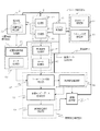
図1は、本発明の実施形態に係る超音波診断装置の構成を示すブロック図である。 FIG. 1 is a block diagram showing a configuration of an ultrasonic diagnostic apparatus according to an embodiment of the present invention.
図1に示すように、本実施形態の超音波診断装置は、システム制御部10と、送受信部
2と、超音波プローブ3と、画像データ生成部4と、異常部位測定部5と、位置・角度解
析部6と、画像表示部7と、パラメータ設定部8等から構成される。
As shown in FIG. 1, the ultrasonic diagnostic apparatus of the present embodiment includes a system control unit 10, a transmission / reception unit 2, an ultrasonic probe 3, an image data generation unit 4, an abnormal site measurement unit 5, a position / An angle analysis unit 6, an image display unit 7, a parameter setting unit 8, and the like are included.
システム制御部10は、システム制御線11を介して上記送受信部2と超音波プローブ
3と、画像データ生成部4と、異常部位測定部5と、位置・角度解析部6と、画像表示部
7と、パラメータ設定部8の動作の同期をとる等の制御を行う。
The system control unit 10 includes the transmission / reception unit 2, the ultrasonic probe 3, the image data generation unit 4, the abnormal site measurement unit 5, the position / angle analysis unit 6, and the image display unit 7 via the system control line 11. And control such as synchronizing the operation of the parameter setting unit 8.
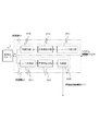
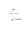
送受信部2は、送信部21と受信部22から構成される。図2は、送受信部2の構成を
示すブロック図である。図2に示すように、送受信部2の送信部21はレートパルス発生
器211と、送信遅延回路212と、駆動回路213とから構成される。また、受信器2
2はNxチャンネルから構成されるA/D変換器221と、受信遅延回路222と、加算
器223等から構成される。
The transmission / reception unit 2 includes a transmission unit 21 and a reception unit 22. FIG. 2 is a block diagram illustrating a configuration of the transmission / reception unit 2. As shown in FIG. 2, the transmission unit 21 of the transmission / reception unit 2 includes a
2 includes an A /
送信部21のレートパルス発生器211は、送信超音波の繰り返し周期を決定するレー
トパルスを生成して送信遅延回路212に供給する。送信遅延回路212は、Nxチャン
ネルの独立な遅延回路から構成されている。送信遅延回路212は、送信超音波を所定の
深さに収束するための遅延時間と、所定の方向に送信するための遅延時間と、所定の方向
に送信するための遅延時間とをレートパルスに与え、このレートパルスを駆動回路213
に供給する。駆動回路213は、Nxチャンネルの独立な駆動回路を有しており、超音波
プローブ3に内蔵されたNx個の振動素子311を駆動して被検体の体内に送信超音波を
放射する。
The
To supply. The drive circuit 213 has an Nx channel independent drive circuit, and drives the
一方、振動素子311から供給されたNxチャンネルの受信信号は、受信部22のAD
変換器211にてデジタル信号に変換され、受信遅延回路222に送られる。
On the other hand, the reception signal of the Nx channel supplied from the
The signal is converted into a digital signal by the
受信遅延回路222は、所定の深さからの受信超音波を収束するための遅延時間と、所
定方向に対して受信指向性を設定するための遅延時間とをA/D変換器211から出力さ
れるNxチャンネルの受信信号の各々に与える。加算器223は、受信遅延回路222か
ら出力されるNxチャンネルの受信信号を加算合成する。即ち、受信遅延回路222と加
算器223により、所定方向から得られた受信信号は整合加算される。なお、受信遅延回
路222および加算器223は、その遅延時間の制御によって複数方向からの受信超音波
を同時に受信する並列同時受信を行うことも可能である。
The
超音波プローブ3は、探触子31とNx個の振動素子311を内蔵している。図3は、
この超音波プローブ3の形状の一例を示す図である。図3に示すように、超音波プローブ
3には探触子31が設けられ、その探触子31の被検体に接する側にはNx個の振動素子
311が設けられている。
The ultrasonic probe 3 includes a probe 31 and
It is a figure which shows an example of the shape of this ultrasonic probe 3. FIG. As shown in FIG. 3, the probe 31 is provided in the ultrasonic probe 3, and Nx
探触子31は、例えばアーチファクト現象を発生しやすくするために、凹面半球形状を
有している。凹面半球形状とすることによって、アーチファクト現象が起こりやすいよう
に、被検体の表面部分に平行な面をできるだけ多く作成することができる。
The probe 31 has a concave hemispherical shape, for example, in order to easily generate an artifact phenomenon. By adopting a concave hemispherical shape, it is possible to create as many planes as possible parallel to the surface portion of the subject so that an artifact phenomenon is likely to occur.
なお、超音波プローブ3の探触子31の形状は、この凹面半球形状に限られるものでは
なく、アーチファクト現象を起こりやすい形状であれば非半球形の形状でもよい。
The shape of the probe 31 of the ultrasonic probe 3 is not limited to the concave hemispherical shape, and may be a non-hemispherical shape as long as an artifact phenomenon is likely to occur.
図4は、探触子31を構成するNx個の振動素子311の配列例を示す図である。図4
(a)〜(d)に示すように、探触子31は1列〜複数列の振動素子311の列から構成
される。図4(a)では、Nx個の振動素子311を一列に配列して構成している。図4
(b)では、Nx個の振動素子311を二列に配列して構成している。図4(c)では、
二列の振動素子311を中間点でクロスして構成している。図4(d)では、三列の振動
素子311の内、中間に一列の振動素子311を配置し、上下の振動素子311の列を中
間点でクロスして構成している。これらいずれの構成を採用しても良い。
FIG. 4 is a diagram illustrating an arrangement example of
As shown to (a)-(d), the probe 31 is comprised from the row | line | column of the
In (b),
Two rows of
図1に戻り、上記超音波プローブ3には、3次元の位置情報を検出する位置角度検出部
32が取り付けられている。位置角度検出部32は、例えば高周波磁場を放射する磁場ソ
ースを有し、一方、超音波探触子31には磁場センサを備えて構成されている。超音波プ
ローブ3は、磁場ソースを基準として超音波探触子31から得られた被検体の異常部位か
らの位置・角度情報を位置角度解析部6へ送出する。探触子31からの位置・角度情報の
変化に伴う超音波画像からアーチファクト現象の種類を特定する。
Returning to FIG. 1, the ultrasonic probe 3 is provided with a position angle detection unit 32 for detecting three-dimensional position information. The position angle detection unit 32 includes, for example, a magnetic field source that radiates a high-frequency magnetic field, and the ultrasonic probe 31 includes a magnetic field sensor. The ultrasonic probe 3 sends the position / angle information from the abnormal part of the subject obtained from the ultrasonic probe 31 to the position angle analysis unit 6 using the magnetic field source as a reference. The type of artifact phenomenon is specified from the ultrasonic image accompanying the change in position / angle information from the probe 31.
画像データ生成部4は、受信部22から出力される整合加算後の受信信号に対し所定の
画像処理を行って画像データを作成する受信信号処理部41と、この作成した画像データ
を超音波の送受信方向に対応させて順次保存するデータ記憶部42を備えている。この画
像データは、主にB(Brightness)モード超音波診断画像を用いる。
The image data generation unit 4 performs predetermined image processing on the reception signal after the matching addition output from the reception unit 22 to generate image data, and the generated image data is converted into an ultrasonic wave. A data storage unit 42 that sequentially stores data corresponding to the transmission / reception directions is provided. As this image data, a B (Brightness) mode ultrasonic diagnostic image is mainly used.
位置角度解析部6は、位置角度情報処理部61と、位置角度データ記憶部62を有する
。位置角度情報処理部61は、位置角度検出部32が検出した位置・角度情報を位置角度
データ記憶部62に記憶するために、位置と角度情報に分けて記憶する。位置角度データ
記憶部62には、この位置・角度情報が順次記憶される。ここでは、これら位置角度検出
部32および位置角度解析部6を含む角度認識機能を角度認識手段と表現するものである
。
The position angle analysis unit 6 includes a position angle information processing unit 61 and a position angle data storage unit 62. The position angle information processing unit 61 stores the position / angle information detected by the position angle detection unit 32 separately into position and angle information in order to store the position / angle information in the position angle data storage unit 62. The position / angle data storage unit 62 sequentially stores the position / angle information. Here, the angle recognition function including the position angle detection unit 32 and the position angle analysis unit 6 is expressed as an angle recognition unit.
異常部位測定部5は、アーチファクト現象検出部51と、実像部位推定部52と、音響
インピーダンス差推定部53と、実像部位硬さ推定部54を備えている。
The abnormal site measurement unit 5 includes an artifact phenomenon detection unit 51, a real image site estimation unit 52, an acoustic impedance difference estimation unit 53, and a real image site hardness estimation unit 54.
アーチファクト現象検出部51は、データ記憶部42に記憶された画像データと位置角
度データ記憶部62に記憶された位置・角度情報とから、アーチファクト現象の種類を特
定し検出する。アーチファクト現象の種類としては、超音波振動によるものとして多重反
射、サイドローブ、グレーティングローブ、鏡面現象、レンズ効果、スライス幅の厚みな
どがある。また、屈折等によるものがある。
The artifact phenomenon detection unit 51 identifies and detects the type of artifact phenomenon from the image data stored in the data storage unit 42 and the position / angle information stored in the position angle data storage unit 62. As the types of artifact phenomenon, there are multiple reflection, side lobe, grating lobe, specular phenomenon, lens effect, slice width thickness and the like due to ultrasonic vibration. In addition, there are those caused by refraction.
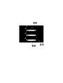
図5は、多重反射の概念を示す図である。探触子31から発せられた超音波は、異常部
位にて複数回反射する。図6は、図5に示す超音波の多重反射が発生した場合の断層像を
示す図である。多重反射により実像を表す反射以外に、複数の虚像が等間隔で映像として
表示される。
FIG. 5 is a diagram showing the concept of multiple reflection. The ultrasonic wave emitted from the probe 31 is reflected a plurality of times at the abnormal part. FIG. 6 is a diagram showing a tomographic image when the multiple reflection of ultrasonic waves shown in FIG. 5 occurs. In addition to the reflection representing a real image by multiple reflection, a plurality of virtual images are displayed as images at equal intervals.
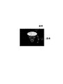
図7は、超音波の多重反射によるコメットライクエコーの概念を示す図である。探触子
31から発せられた超音波が異常部位表面と異常部位内部で複数回反射する。図8は、図
7に示す超音波の多重反射によるコメットライクエコーの断層像を示す図である。正常組
織内に音響インピーダンス差が大きい小さな異常部位が存在する場合に発生しやすい。他
にコメットサインと呼ばれることもある。
FIG. 7 is a diagram showing the concept of a comet-like echo by multiple reflection of ultrasonic waves. The ultrasonic wave emitted from the probe 31 is reflected a plurality of times on the surface of the abnormal part and inside the abnormal part. FIG. 8 is a diagram showing a tomographic image of a comet-like echo due to multiple reflection of ultrasonic waves shown in FIG. This is likely to occur when there is a small abnormal site with a large acoustic impedance difference in normal tissue. It is sometimes called the comet sign.
図9は、屈折が起こりやすい状態を示す図である。筋肉と脂肪層のように音響インピー
ダンス差が存在する場合に屈折しやすいため起こりやすいといえる。図10は、屈折によ
る虚像が生じる概念を示す図である。超音波が屈折することにより、実像部位とは異なっ
た点に虚像を生じさせている。
FIG. 9 is a diagram showing a state where refraction easily occurs. This is likely to occur because there is a tendency to refract when there is an acoustic impedance difference such as muscle and fat layers. FIG. 10 is a diagram illustrating the concept of generating a virtual image due to refraction. By refracting the ultrasonic wave, a virtual image is generated at a point different from the real image portion.
例えば、映像データとして図8に示すようなコメットライクエコーが検出されれば、多
重反射によるアーチファクト現象が発生していると特定する。
For example, if a comet-like echo as shown in FIG. 8 is detected as video data, it is specified that an artifact phenomenon due to multiple reflection has occurred.
なお、コメットライクエコーのように類別しやすいアーチファクト現象でない場合は、
被検体に対する超音波プローブ3の角度を変え、検出されるアーチファクト現象の変化を
画像データで取得し、アーチファクト現象の類別を行うようにしても良い。または、被検
体に対する超音波プローブ3の圧迫強度を変化させ、検出されるアーチファクト現象の変
化を画像データで取得し、アーチファクト現象の類別を行うようにしても良い。このアー
チファクト現象の類別判別としては、主に過去のアーチファクト現象のデータと正常組織
の画像データとをパターンマッチング(類別比較)させることにより行う。
If it is not an easily categorized artifact such as a comet-like echo,
The angle of the ultrasonic probe 3 with respect to the subject may be changed, and the detected change in the artifact phenomenon may be acquired as image data to classify the artifact phenomenon. Alternatively, the compression strength of the ultrasonic probe 3 against the subject may be changed, and the detected change in the artifact phenomenon may be acquired as image data to classify the artifact phenomenon. The classification of the artifact phenomenon is mainly performed by pattern matching (category comparison) of past artifact phenomenon data and normal tissue image data.
図1に戻り、実像部位推定部52は、超音波プローブ3の位置の変化に対するアーチフ
ァクト現象検出部51によるアーチファクト現象の映像データ変化量から、アーチファク
ト現象の原因となる異常部位の位置を推定する。その推定方法としては、過去の同様のア
ーチファクト現象のデータと正常組織の画像データとをパターンマッチングさせることに
より行う。
Returning to FIG. 1, the real image region estimation unit 52 estimates the position of the abnormal region that causes the artifact phenomenon from the amount of change in the image data of the artifact phenomenon by the artifact phenomenon detection unit 51 with respect to the change in the position of the ultrasonic probe 3. As the estimation method, pattern matching is performed between the same artifact data in the past and the image data of normal tissue.
その後、実像部位推定部52は推定される異常部位の位置の超音波断層画像を画像表示
部7に表示させる。超音波断層画像とは、図6、図8、図10に示すような超音波を用い
て生体内の臓器などの状態 を把握し,それを二次元の映像にして形態学的な診断に利用
する方法である。
Thereafter, the real image site estimation unit 52 causes the image display unit 7 to display an ultrasonic tomographic image of the estimated location of the abnormal site. Ultrasound tomographic images use the ultrasonic waves shown in Figs. 6, 8, and 10 to grasp the state of organs and the like in a living body and use them as a two-dimensional image for morphological diagnosis. It is a method to do.
以下、アーチファクト現象から異常部位の位置を推定するパターンマッチングの8種類
の動作を説明する。
Hereinafter, eight types of operations of pattern matching for estimating the position of the abnormal part from the artifact phenomenon will be described.
(1)超音波断層画像から検出されるアーチファクト現象が等間隔で映った複数のエコ
ーである場合は、最もエコー強度が強い。つまり、輝度が明るい部分に異常部位が存在す
ると推定する。具体的には、図6に示すような場合である。
(1) When the artifact phenomenon detected from the ultrasonic tomographic image is a plurality of echoes reflected at equal intervals, the echo intensity is strongest. That is, it is estimated that an abnormal part exists in a bright part. Specifically, this is the case as shown in FIG.
(2)超音波断層画像から検出されるアーチファクト現象が放物線形状またはコメット
ライクエコーの場合は、等間隔で映った複数のエコーの中から最もエコー強度が強い。つ
まり、輝度が明るい部分に異常部位が存在すると推定する。具体的には、図8に示すよう
な場合である。
(2) When the artifact phenomenon detected from the ultrasonic tomographic image is a parabolic shape or a comet-like echo, the echo intensity is the strongest among a plurality of echoes shown at equal intervals. That is, it is estimated that an abnormal part exists in a bright part. Specifically, this is the case as shown in FIG.
(3)超音波断層画像から検出されるアーチファクト現象が放物線形状またはコメット
ライクエコー形状であり、超音波端子の移動によりコメットライクエコーの形状が変化す
る場合は、コメットライクエコーの縞模様の向きが変化する点に異常部位が存在すると推
定する。このコメットライクエコーの検出には、リニア電子スキャンやセクタ電子スキャ
ン、コンベックス電子スキャンにより検出された場合も同様である。
(3) When the artifact phenomenon detected from the ultrasonic tomographic image is a parabolic shape or a comet-like echo shape and the shape of the comet-like echo changes due to movement of the ultrasonic terminal, the direction of the stripe pattern of the comet-like echo is Presume that there is an abnormal part at the changing point. The detection of this comet-like echo is the same when it is detected by linear electronic scan, sector electronic scan, or convex electronic scan.
(4)超音波断層画像から検出されるアーチファクト現象が後方エコー増強現象である
場合は、輝度が強いエコー画像に囲まれた輝度が弱い部分が周りの硬い部位に比べて軟化
した部位であると推定する。
(4) When the artifact phenomenon detected from the ultrasonic tomographic image is a backward echo enhancement phenomenon, the low-luminance portion surrounded by the high-luminance echo image is a softened portion compared to the surrounding hard portion presume.
(5)超音波断層画像から検出されるアーチファクト現象が後方エコー減弱現象である
場合は、輝度が弱いエコー画像に囲まれた輝度が強い部分が異常部位であると推定する。
(5) When the artifact phenomenon detected from the ultrasonic tomographic image is a backward echo attenuation phenomenon, it is estimated that a portion with high luminance surrounded by an echo image with low luminance is an abnormal part.
(6)超音波断層画像から検出されるアーチファクト現象が2つ以上の形状が相似した
エコーと相似したエコーの間に異なった形状のエコーが存在する場合、それらのエコー群
に超音波プローブ3を近づけた場合に残るエコー部分が異常部位であると推定する。
(6) When echoes having different shapes exist between two or more echoes similar in shape to artifacts detected from an ultrasonic tomographic image, the ultrasonic probe 3 is placed in those echo groups. It is estimated that the echo portion remaining when approaching is an abnormal part.
(7)超音波断層画像から検出されるアーチファクト現象が2つ以上の形状が相似した
エコーである場合で、超音波プローブ3の移動により消失しないエコー部が異常部位であ
ると推定する。
(7) When the artifact phenomenon detected from the ultrasonic tomographic image is an echo having two or more similar shapes, it is estimated that an echo portion that does not disappear due to the movement of the ultrasonic probe 3 is an abnormal part.
(8)音響インピーダンス差推定部53は、超音波プローブ3の被検体に対する位置や
角度の変化によるアーチファクト現象検出部51によるアーチファクト現象の変化から、
異常部位と周囲組織との音響インピーダンス差を推定する。
(8) The acoustic impedance difference estimation unit 53 is based on the change in the artifact phenomenon by the artifact phenomenon detection unit 51 due to the change in the position and angle of the ultrasonic probe 3 with respect to the subject.
Estimate the acoustic impedance difference between the abnormal site and surrounding tissue.
例えば、異常部位と周囲組織との音響インピーダンスの差の推定は、推定される異常部
位のエコー強度と正常組織のエコー強度との差を利用することにより行う。または、あら
かじめ設定された対象測定深度と超音波プローブ3間との距離の変化により生じる受信信
号の時間的変化を平滑化するために、受信機内部の利得を時間によって変化させるSTC
(Sensitivity Time Control)処理を行った異常部位のエコー
強度と正常組織のエコー強度との差を利用することにより行う。または、検査対象物の表
面からの深度に応じて増幅率を調整するTGC(Time Gain Compensa
tion)処理を行った異常部位のエコー強度と正常組織のエコー強度との差を利用する
ことにより行うこともできる。
For example, the difference in acoustic impedance between the abnormal part and the surrounding tissue is estimated by using the difference between the estimated echo intensity of the abnormal part and the echo intensity of the normal tissue. Alternatively, in order to smooth the temporal change of the received signal caused by the change in the distance between the target measurement depth set in advance and the ultrasonic probe 3, the STC that changes the gain inside the receiver with time.
(Sensitivity Time Control) This is performed by utilizing the difference between the echo intensity of the abnormal part subjected to the process and the echo intensity of the normal tissue. Alternatively, TGC (Time Gain Compensa) that adjusts the amplification factor according to the depth from the surface of the inspection object.
It is also possible to make use of the difference between the echo intensity of the abnormal site subjected to the (ion) process and the echo intensity of the normal tissue.
これらの異常部位のエコー強度と正常組織のエコー強度の差と、異常部位と正常部位の
音響インピーダンス差には正の相関関係があり、過去データ等から事前に算出した関係式
に従って異常部位と正常部位の音響インピーダンス差を導き出すことができる。
There is a positive correlation between the difference between the echo intensity of these abnormal parts and the echo intensity of normal tissues, and the acoustic impedance difference between the abnormal part and the normal part. The acoustic impedance difference of the part can be derived.
図1の実像部位硬さ推定部54は、音響インピーダンス差推定部53により導き出した
音響インピーダンス差より、音響インピーダンス差と異常部位と正常部位の硬さの差には
正の相関関係があることから、過去データ等から事前に算出した関係式に従って異常部位
と正常部位の硬さの差を導き出すことができる。正常部位の硬さは過去データ等から導き
出せるため、上記異常部位と正常部位の硬さの差と正常部位の硬さから異常部位の硬さを
推定することができる。
The real image part hardness estimation unit 54 of FIG. 1 has a positive correlation between the acoustic impedance difference and the hardness difference between the abnormal part and the normal part, based on the acoustic impedance difference derived by the acoustic impedance difference estimation part 53. The difference in hardness between the abnormal part and the normal part can be derived according to a relational expression calculated in advance from past data or the like. Since the hardness of the normal part can be derived from past data or the like, the hardness of the abnormal part can be estimated from the difference in hardness between the abnormal part and the normal part and the hardness of the normal part.
画像表示部7は、実像部位推定部52により推定された実像部位の位置を超音波断層画
像として表示する。この際、複数の振動素子から得られた画像を同時に表示しても良い。
また、指定した画像のみを表示しても良い。また、前記実像部位推定部52により推定さ
れた実像部位の画像のみを表示しても良い。
The image display unit 7 displays the position of the real image part estimated by the real image part estimation unit 52 as an ultrasonic tomographic image. At this time, images obtained from a plurality of vibration elements may be displayed simultaneously.
Further, only the designated image may be displayed. Further, only the image of the real image part estimated by the real image part estimation unit 52 may be displayed.
パラメータ設定部8は、表示モード設定部81と、スキャン方式設定部82を含む構成
である。表示モード設定部81は、Bモードに表示方法を設定する。スキャン方式設定部
82は、スキャン方式を設定する。例えば、機械スキャン方式、電子スキャン方式、手動
スキャン方式などを選択する。また機械スキャン方式では、機械セクタスキャン方式、機
械ラジアルスキャン方式が利用できる。電子スキャン方式では、リニア電子スキャン方式
やセクタ電子スキャン方式、コンベックス電子スキャン方式が利用できる。
The parameter setting unit 8 includes a display mode setting unit 81 and a scan method setting unit 82. The display mode setting unit 81 sets the display method to the B mode. The scan method setting unit 82 sets a scan method. For example, a mechanical scan method, an electronic scan method, a manual scan method, or the like is selected. In the mechanical scanning method, a mechanical sector scanning method or a mechanical radial scanning method can be used. In the electronic scanning method, a linear electronic scanning method, a sector electronic scanning method, or a convex electronic scanning method can be used.
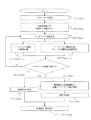
次に、実施形態の動作について図11を用いて説明する。 Next, the operation of the embodiment will be described with reference to FIG.
図11は、実施形態の一連の動作を示すフローチャートである。 FIG. 11 is a flowchart illustrating a series of operations according to the embodiment.
まず、パラメータ設定部8で、表示モードとスキャン方式を設定する(ステップ301
)。本実施形態では表示モードをBモードとし、スキャン方式は電子スキャン方式である
として説明する。その後、システム制御部10によりシステムを起動させ、超音波プロー
ブ3を被検体に接触させる(ステップ302)。接触した際に送信部21から超音波が発
生され、アーチファクト現象を発生させる(ステップ303)。アーチファクト現象を含
んだ反射波を受信部22により受信する。受信した反射波は、受信信号処理部41へ送ら
れ、画像データとして処理された後、データ記憶部42へ記憶される(ステップ304−
1)。また、受信信号を取得した際の超音波プローブ3の位置・角度情報は位置角度検出
部32で検出され、位置角度情報処理部61へ送られる。そして、位置角度情報処理部6
1は位置・角度情報を処理して位置角度データ記憶部62へ記憶する(ステップ304−
2)。
First, the display mode and scan method are set by the parameter setting unit 8 (step 301).
). In the present embodiment, description will be made assuming that the display mode is the B mode and the scanning method is the electronic scanning method. Thereafter, the system is started by the system control unit 10, and the ultrasonic probe 3 is brought into contact with the subject (step 302). When contact is made, ultrasonic waves are generated from the transmitter 21 to cause an artifact phenomenon (step 303). The reflected wave including the artifact phenomenon is received by the receiving unit 22. The received reflected wave is sent to the reception signal processing unit 41, processed as image data, and then stored in the data storage unit 42 (step 304-
1). Further, the position / angle information of the ultrasonic probe 3 when the received signal is acquired is detected by the position angle detection unit 32 and sent to the position angle information processing unit 61. And the position angle information processing part 6
1 processes the position / angle information and stores it in the position angle data storage unit 62 (step 304-
2).
アーチファクト現象検出部51は、データ記憶部42に記憶された画像データと位置角
度データ記憶部62に記憶された位置角度情報を、過去のアーチファクト現象のデータ等
と比較させアーチファクト現象を類別し、推定する(ステップ305)。1度のデータ取
得ではアーチファクト現象を類別することができない場合は、超音波探触子の位置・角度
を変更し、アーチファクト現象の類別をさらに行う(ステップ305)。
The artifact phenomenon detection unit 51 compares the image data stored in the data storage unit 42 and the position angle information stored in the position angle data storage unit 62 with past artifact phenomenon data and the like to classify and estimate the artifact phenomenon. (Step 305). If the artifact phenomenon cannot be classified with one data acquisition, the position / angle of the ultrasonic probe is changed to further classify the artifact phenomenon (step 305).
次に実像部位推定部52は、アーチファクト現象検出部51によって検出されるアーチ
ファクト現象の映像データ変化量から、アーチファクト現象の原因となる正常部位と音響
インピーダンス差が大きい部位(異常部位)の位置を推定する(ステップ306)。
Next, the real image part estimation unit 52 estimates the position of a normal part that causes the artifact phenomenon and a part having a large acoustic impedance difference (abnormal part) from the video data change amount of the artifact phenomenon detected by the artifact phenomenon detection unit 51. (Step 306).
最後に、表示部7に上記求めた異常部位の位置を表示する。 Finally, the obtained position of the abnormal part is displayed on the display unit 7.
また、超音波プローブ3の被検体に対する位置や角度の変化による前記アーチファクト
現象検出部51によるアーチファクト現象の変化から、アーチファクト現象発生原因とな
る部位(異常部位)と周囲組織の音響インピーダンス差を推定する(ステップ307)。
この際、異常部位の位置情報が必要となるが、上記実像部位推定部52によって推定され
る位置でもよいし、もともとの対象物付近の深度を設定して上記音響インピーダンス差の
推定に用いても良い。
Further, from the change in the artifact phenomenon by the artifact phenomenon detection unit 51 due to the change in the position and angle of the ultrasonic probe 3 with respect to the subject, the acoustic impedance difference between the site (abnormal site) causing the artifact phenomenon and the surrounding tissue is estimated. (Step 307).
At this time, the position information of the abnormal part is required, but the position estimated by the real image part estimation unit 52 may be used, or the depth near the original object may be set and used for the estimation of the acoustic impedance difference. good.
次に、実像部位硬さ推定部54は、音響インピーダンス差推定部53により導き出した
音響インピーダンス差より、音響インピーダンス差と異常部位と正常部位の硬さの差には
正の相関関係があることから、過去データ等から事前に算出した関係式に従って導き出す
ことができる(ステップ308)。
Next, the real image region hardness estimation unit 54 has a positive correlation between the acoustic impedance difference and the hardness difference between the abnormal region and the normal region, based on the acoustic impedance difference derived by the acoustic impedance difference estimation unit 53. Then, it can be derived according to the relational expression calculated in advance from the past data or the like (step 308).
最後に、表示部7に上記求めた異常部位の硬さを表示する(ステップ309)。 Finally, the obtained hardness of the abnormal part is displayed on the display unit 7 (step 309).
このようにすることによって、アーチファクト現象を用いて、音響インピーダンス差の
激しい部位、つまり異常部位の位置および硬さを推定することができる。
By doing so, it is possible to estimate the position and hardness of a part having a large acoustic impedance difference, that is, an abnormal part, using the artifact phenomenon.
なお、本発明は、発明の要旨を逸脱しない範囲において、上述した実施形態を適宜設計
変更することが可能であり、必要に応じて実施形態を適宜組み合わせても良い。
In the present invention, the above-described embodiments can be appropriately changed in design without departing from the gist of the invention, and the embodiments may be appropriately combined as necessary.
10 … システム制御部
11 … システム制御線
2 … 送受信部
21 … 送信部
211 … レートパルス発生器
212 … 送信遅延回路
213 … 駆動回路
22 … 受信部
221 … A/D変換部
222 … 受信遅延回路
223 … 加算器
3 … 超音波プローブ
31 … 探触子
311 … 振動素子
32 … 位置角度検出部
4 … 画像データ生成部
41 … 受信信号処理部
42 … データ記憶部
5 … 異常部位測定部
51 … アーチファクト現象検出部
52 … 実像部位推定部
53 … 音響インピーダンス差推定部
54 … 実像部位硬さ推定部
6 … 位置・角度解析部
7 … 画像表示部
8 … パラメータ設定部
81 … 表示モード設定部
82 … スキャン方式設定部
DESCRIPTION OF SYMBOLS 10 ... System control part 11 ... System control line 2 ... Transmission / reception part 21 ...
Claims (1)
受信する超音波探触子と、
前記超音波探触子の位置および方向情報を認識する位置・角度認識手段と、
前記超音波探触子によって受信された反射波と、前記位置・角度検出手段により導き出
された前記超音波探触子の位置情報と、からアーチファクト現象を検出するアーチファク
ト現象検出手段と、
前記アーチファクト現象検出手段から検出されたアーチファクト現象に基づいて前記異
常部位の硬さを算出する異常部位硬さ算出手段と、
前記異常部位検出手段により特定された硬さを表示する表示手段と、
を備えることを特徴とする超音波診断装置。 An ultrasonic probe that transmits ultrasonic waves to the subject and receives reflected waves of the ultrasonic waves with respect to the abnormal part of the subject;
Position / angle recognition means for recognizing position and direction information of the ultrasonic probe;
Artifact phenomenon detection means for detecting an artifact phenomenon from the reflected wave received by the ultrasonic probe and the position information of the ultrasonic probe derived by the position / angle detection means,
Abnormal part hardness calculation means for calculating the hardness of the abnormal part based on the artifact phenomenon detected from the artifact phenomenon detection means;
Display means for displaying the hardness specified by the abnormal part detecting means;
An ultrasonic diagnostic apparatus comprising:
Priority Applications (1)
| Application Number | Priority Date | Filing Date | Title |
|---|---|---|---|
| JP2009266462A JP2011110102A (en) | 2009-11-24 | 2009-11-24 | Ultrasonic diagnostic apparatus |
Applications Claiming Priority (1)
| Application Number | Priority Date | Filing Date | Title |
|---|---|---|---|
| JP2009266462A JP2011110102A (en) | 2009-11-24 | 2009-11-24 | Ultrasonic diagnostic apparatus |
Publications (1)
| Publication Number | Publication Date |
|---|---|
| JP2011110102A true JP2011110102A (en) | 2011-06-09 |
Family
ID=44232923
Family Applications (1)
| Application Number | Title | Priority Date | Filing Date |
|---|---|---|---|
| JP2009266462A Pending JP2011110102A (en) | 2009-11-24 | 2009-11-24 | Ultrasonic diagnostic apparatus |
Country Status (1)
| Country | Link |
|---|---|
| JP (1) | JP2011110102A (en) |
Cited By (1)
| Publication number | Priority date | Publication date | Assignee | Title |
|---|---|---|---|---|
| JP2016522074A (en) * | 2013-06-28 | 2016-07-28 | コーニンクレッカ フィリップス エヌ ヴェKoninklijke Philips N.V. | Ultrasound acquisition feedback guidance for target view |
-
2009
- 2009-11-24 JP JP2009266462A patent/JP2011110102A/en active Pending
Cited By (1)
| Publication number | Priority date | Publication date | Assignee | Title |
|---|---|---|---|---|
| JP2016522074A (en) * | 2013-06-28 | 2016-07-28 | コーニンクレッカ フィリップス エヌ ヴェKoninklijke Philips N.V. | Ultrasound acquisition feedback guidance for target view |
Similar Documents
| Publication | Publication Date | Title |
|---|---|---|
| US11635514B2 (en) | Imaging methods and apparatuses for performing shear wave elastography imaging | |
| CN105816205B (en) | Sparse tracking in acoustic radiation force Pulse Imageing | |
| CN104042247B (en) | It is imaged using the ultrasonic ARFI displacements in auto-adaptive time stage | |
| US8784317B2 (en) | Signal processing apparatus, ultrasonic apparatus, control method for signal processing apparatus, and control method for ultrasonic apparatus | |
| US8317708B2 (en) | Setting an optimal image parameter in an ultrasound system | |
| US10687786B2 (en) | Ultrasound inspection apparatus, ultrasound inspection method and recording medium | |
| KR101100464B1 (en) | Ultrasound system and method for providing three-dimensional ultrasound image based on sub region of interest | |
| US20120065512A1 (en) | Ultrasonic diagnostic apparatus and ultrasonic image processng apparatus | |
| US9566044B2 (en) | Medical image display apparatus and ultrasonic diagnosis apparatus | |
| US9151841B2 (en) | Providing an ultrasound spatial compound image based on center lines of ultrasound images in an ultrasound system | |
| US9855025B2 (en) | Ultrasonic diagnostic apparatus and ultrasonic image processing apparatus | |
| KR20160140858A (en) | Ultrasound imaging system and method for tracking a specular reflector | |
| US10537305B2 (en) | Detecting amniotic fluid position based on shear wave propagation | |
| JP2006122666A (en) | Ultrasonic imaging apparatus | |
| CN110893103A (en) | Angle for ultrasound-based shear wave imaging | |
| US20120203111A1 (en) | Ultrasonic diagnostic apparatus, ultrasonic image processing apparatus, and ultrasonic image acquisition method | |
| JP2010012311A (en) | Ultrasonic diagnostic apparatus | |
| US10792014B2 (en) | Ultrasound inspection apparatus, signal processing method for ultrasound inspection apparatus, and recording medium | |
| JP5623609B2 (en) | Ultrasonic diagnostic equipment | |
| JP2011110102A (en) | Ultrasonic diagnostic apparatus | |
| CN114867418A (en) | System and method for evaluating placenta | |
| JP2011110101A (en) | Ultrasonic diagnostic apparatus | |
| CN117224161A (en) | Ultrasonic imaging method and ultrasonic imaging system | |
| US20090005681A1 (en) | Ultrasound System And Method Of Forming Ultrasound Image | |
| JP5292179B2 (en) | Ultrasonic diagnostic equipment |
Legal Events
| Date | Code | Title | Description |
|---|---|---|---|
| RD02 | Notification of acceptance of power of attorney |
Free format text: JAPANESE INTERMEDIATE CODE: A7422 Effective date: 20111125 |
|
| RD04 | Notification of resignation of power of attorney |
Free format text: JAPANESE INTERMEDIATE CODE: A7424 Effective date: 20111205 |