JP2011106981A - Scintillator array - Google Patents
Scintillator array Download PDFInfo
- Publication number
- JP2011106981A JP2011106981A JP2009262632A JP2009262632A JP2011106981A JP 2011106981 A JP2011106981 A JP 2011106981A JP 2009262632 A JP2009262632 A JP 2009262632A JP 2009262632 A JP2009262632 A JP 2009262632A JP 2011106981 A JP2011106981 A JP 2011106981A
- Authority
- JP
- Japan
- Prior art keywords
- scintillator
- crystal
- array
- crystals
- baso
- Prior art date
- Legal status (The legal status is an assumption and is not a legal conclusion. Google has not performed a legal analysis and makes no representation as to the accuracy of the status listed.)
- Pending
Links
- 239000013078 crystal Substances 0.000 claims abstract description 95
- 239000000463 material Substances 0.000 claims abstract description 44
- 230000005855 radiation Effects 0.000 claims description 9
- 238000004519 manufacturing process Methods 0.000 description 8
- 239000004519 grease Substances 0.000 description 6
- 238000000034 method Methods 0.000 description 6
- 230000003287 optical effect Effects 0.000 description 6
- 239000000843 powder Substances 0.000 description 6
- 239000011347 resin Substances 0.000 description 6
- 229920005989 resin Polymers 0.000 description 6
- 230000000052 comparative effect Effects 0.000 description 5
- 239000007788 liquid Substances 0.000 description 4
- 239000000203 mixture Substances 0.000 description 4
- 238000002600 positron emission tomography Methods 0.000 description 4
- 238000001514 detection method Methods 0.000 description 3
- 238000002844 melting Methods 0.000 description 3
- 230000008018 melting Effects 0.000 description 3
- 239000002904 solvent Substances 0.000 description 3
- 239000004925 Acrylic resin Substances 0.000 description 2
- 229920000178 Acrylic resin Polymers 0.000 description 2
- 230000005251 gamma ray Effects 0.000 description 2
- 238000003384 imaging method Methods 0.000 description 2
- 230000001678 irradiating effect Effects 0.000 description 2
- 238000009206 nuclear medicine Methods 0.000 description 2
- 239000002245 particle Substances 0.000 description 2
- 238000002310 reflectometry Methods 0.000 description 2
- 238000002603 single-photon emission computed tomography Methods 0.000 description 2
- 229910018072 Al 2 O 3 Inorganic materials 0.000 description 1
- YCKRFDGAMUMZLT-UHFFFAOYSA-N Fluorine atom Chemical compound [F] YCKRFDGAMUMZLT-UHFFFAOYSA-N 0.000 description 1
- 239000004372 Polyvinyl alcohol Substances 0.000 description 1
- 238000003776 cleavage reaction Methods 0.000 description 1
- 230000007423 decrease Effects 0.000 description 1
- 238000009826 distribution Methods 0.000 description 1
- 239000003814 drug Substances 0.000 description 1
- 229940079593 drug Drugs 0.000 description 1
- 239000003822 epoxy resin Substances 0.000 description 1
- 230000005284 excitation Effects 0.000 description 1
- 229910052731 fluorine Inorganic materials 0.000 description 1
- 239000011737 fluorine Substances 0.000 description 1
- 239000011259 mixed solution Substances 0.000 description 1
- 238000002156 mixing Methods 0.000 description 1
- 238000012986 modification Methods 0.000 description 1
- 230000004048 modification Effects 0.000 description 1
- 229920000647 polyepoxide Polymers 0.000 description 1
- 229920001225 polyester resin Polymers 0.000 description 1
- 239000004645 polyester resin Substances 0.000 description 1
- 229920005596 polymer binder Polymers 0.000 description 1
- 239000002491 polymer binding agent Substances 0.000 description 1
- 229920002451 polyvinyl alcohol Polymers 0.000 description 1
- 230000007017 scission Effects 0.000 description 1
- 229920002050 silicone resin Polymers 0.000 description 1
- 238000003860 storage Methods 0.000 description 1
Images
Landscapes
- Measurement Of Radiation (AREA)
- Luminescent Compositions (AREA)
Abstract
Description
本発明は、放射線が入射すると内部で蛍光が発生する複数のシンチレータ結晶を有するシンチレータアレイに関し、特に、複数のシンチレータ結晶の間隙が反射材で充填されているシンチレータアレイに関する。 The present invention relates to a scintillator array having a plurality of scintillator crystals that generate fluorescence inside when radiation is incident, and more particularly to a scintillator array in which gaps between the plurality of scintillator crystals are filled with a reflecting material.
被検体に陽電子放射性同位元素(RI:Radio Isotope)標識の薬剤が投与されると、消滅γ線が放出される。PET(Positron Emission Tomography)、SPECT(Single Photon Emission Computed Tomography)、ガンマカメラなどの核医学イメージング装置は、この放射線を検出することにより、被検体内のRIの分布像を得る装置である。 When a positron emitting isotope (RI) -labeled drug is administered to the subject, annihilation γ rays are emitted. Nuclear medicine imaging apparatuses such as PET (Positron Emission Tomography), SPECT (Single Photon Emission Computed Tomography), and gamma cameras are apparatuses that obtain a distribution image of RI in a subject by detecting this radiation.
このような核医学イメージング装置には、複数のシンチレータ結晶を有するシンチレータアレイが利用されている。このようなシンチレータアレイは、例えば、細長形状のシンチレータ結晶を、その長手方向と直交する方向に二次元状に所定間隔で配列した構造に形成されている。 Such a nuclear medicine imaging apparatus uses a scintillator array having a plurality of scintillator crystals. Such a scintillator array is formed, for example, in a structure in which elongated scintillator crystals are two-dimensionally arranged at predetermined intervals in a direction orthogonal to the longitudinal direction.
シンチレータアレイは、光電子増倍管などの光検出器に接続され、放射線検出器として用いられる。しかし、シンチレータアレイに放射線が入射すると放射線入射箇所のシンチレータ結晶が発光し、接続された光検出器に放射線強度に比例した光量を出力する機能を有している。 The scintillator array is connected to a photodetector such as a photomultiplier tube and used as a radiation detector. However, when radiation enters the scintillator array, the scintillator crystal at the radiation incident site emits light, and has a function of outputting a light amount proportional to the radiation intensity to the connected photodetector.
また、光反射率の大きい板材を使用して、所定の間隔で整列した封入穴を持った結晶収納容器を製作し、その封入穴の中にシンチレータ結晶を嵌合してシンチレータアレイを製造する方法が提案されている(例えば、特許文献2参照)。 Also, a method of manufacturing a scintillator array by manufacturing a crystal container having enclosing holes aligned at a predetermined interval using a plate material having a high light reflectance, and fitting a scintillator crystal in the enclosing holes. Has been proposed (see, for example, Patent Document 2).
また、ブロック状に切り出したシンチレータ結晶に一定間隔の切込み溝を縦横に形成したのち、その切込み溝に反射材を充填する技術も提案されている(例えば、特許文献3参照)。 In addition, a technique has also been proposed in which cut grooves having a predetermined interval are formed vertically and horizontally in a scintillator crystal cut into a block shape, and the cut grooves are filled with a reflective material (see, for example, Patent Document 3).
さらに、複数のシンチレータ結晶の配列精度と検出精度とが良好なシンチレータアレイを簡単に製造できるアレイ製造方法も提案されている。このアレイ製造方法では、複数のシンチレータ結晶を二次元状に配列してから、間隙に充填した混合液を凝固させるので、複数のシンチレータ結晶の位置精度が良好である(例えば、特許文献4参照)。 Furthermore, an array manufacturing method that can easily manufacture a scintillator array with good alignment accuracy and detection accuracy of a plurality of scintillator crystals has also been proposed. In this array manufacturing method, a plurality of scintillator crystals are arranged two-dimensionally and then the mixed liquid filled in the gap is solidified, so that the positional accuracy of the plurality of scintillator crystals is good (see, for example, Patent Document 4). .
また、ガンマ線検出装置用に、一般的なシンチレータ結晶であるBGO(Bi4Ge3O12)、GSO(Gd2SiO5)、LSO(Lu2SiO5)、等より極めて高い発光量、蛍光の減衰時間が極めて短い特徴を有するPrを含むガーネット型酸化物シンチレータ用単結晶を提供する提案もある。 Also, for gamma ray detection devices, the emission level and fluorescence of extremely higher light emission than BGO (Bi 4 Ge 3 O 12 ), GSO (Gd 2 SiO 5 ), LSO (Lu 2 SiO 5 ), etc., which are general scintillator crystals. There is also a proposal to provide a single crystal for a garnet-type oxide scintillator containing Pr having a characteristic of extremely short decay time.
そのシンチレータ用単結晶の製造方法では、(PrxLu1−x)3AlyO12で表される初期融液を結晶化して、シンチレータ用単結晶を製造する方法において、初期融液のxが0.02≦x≦0.03、yが5<y≦5.2となるように調整する(例えば、特許文献5参照)。 In the method for producing a scintillator single crystal, the initial melt represented by (Pr x Lu 1-x ) 3 Al y O 12 is crystallized to produce a scintillator single crystal. Is adjusted to 0.02 ≦ x ≦ 0.03, and y is set to 5 <y ≦ 5.2 (for example, see Patent Document 5).
特許文献1には反射材の形成方法、特許文献2にはアレイの製造方法、特許文献3には反射材の形成方法および材質が開示されているが、厚さに関する記述は無く最適な厚さは不明であった。 Patent Document 1 discloses a reflective material forming method, Patent Document 2 discloses an array manufacturing method, and Patent Document 3 discloses a reflective material forming method and material. Was unknown.
さらには、これら従来技術文献で開示された反射材は、弗素樹脂やポリエステル系樹脂であり発光波長が400nm以下の発光では反射率が90%以下と反射能が低いため、シンチレータ結晶から出力される光量が減少するという問題がある。 Furthermore, the reflective materials disclosed in these prior art documents are fluorine resin or polyester resin, and the light emission wavelength is 400 nm or less, and the reflectivity is 90% or less and the reflectivity is low. Therefore, the light is output from the scintillator crystal. There is a problem that the amount of light decreases.
特許文献4には、反射材が0.15mmの層厚のBaSO4でよいこと、シンチレータ結晶としてPr:LuAG結晶を利用できること、シンチレータ結晶の蛍光の波長が400nm以下でよいこと、が開示されている。 Patent Document 4 discloses that the reflecting material may be BaSO 4 having a layer thickness of 0.15 mm, a Pr: LuAG crystal can be used as the scintillator crystal, and the fluorescence wavelength of the scintillator crystal may be 400 nm or less. Yes.
さらに、特許文献5には、シンチレータ結晶を(PrxLu1−x)3AlyO12で形成できることが開示されている。しかし、特許文献5は、シンチレータ結晶のことしか開示されておらず、シンチレータアレイとして必要な反射材のことは開示されていない。 Further, Patent Document 5 discloses that a scintillator crystal can be formed of (Pr x Lu 1-x ) 3 Al y O 12 . However, Patent Document 5 only discloses a scintillator crystal, and does not disclose a reflector necessary as a scintillator array.
本発明は上述のような課題に鑑みてなされたものであり、良好な特性のシンチレータ結晶を正確な形状に良好な生産性で量産することができ、シンチレータ結晶の蛍光を反射材により95%以上の反射率で反射することができ、分解能が良好なシンチレータアレイを提供するものである。 The present invention has been made in view of the above-mentioned problems, and scintillator crystals having good characteristics can be mass-produced in an accurate shape with good productivity, and the scintillator crystal fluorescence is 95% or more by a reflecting material. It is possible to provide a scintillator array that can reflect with a high reflectance and has a good resolution.
本発明のシンチレータアレイは、放射線が入射すると内部で蛍光が発生する複数のシンチレータ結晶を有するシンチレータアレイであって、PrがドープされたLu3Al5O12結晶で細長形状の複数のシンチレータ結晶が形成されており、複数のシンチレータ結晶が長手方向と直交する方向に0.05mm以上0.2mm以下の間隙で二次元状に配列されており、配列された複数のシンチレータ結晶の間隙にBaSO4を主成分とする反射材が充填されている。 The scintillator array of the present invention is a scintillator array having a plurality of scintillator crystals that generate fluorescence inside when radiation is incident, and a plurality of elongated scintillator crystals of Pr 3 doped with Lu 3 Al 5 O 12 crystals. A plurality of scintillator crystals are arranged in a two-dimensional manner with a gap of 0.05 mm or more and 0.2 mm or less in a direction orthogonal to the longitudinal direction, and BaSO 4 is placed in the gaps of the arranged scintillator crystals. A reflecting material as a main component is filled.
従って、本発明のシンチレータアレイでは、PrがドープされたLu3Al5O12結晶からなるシンチレータ結晶は、ガンマ線励起による発光量が従来のBGOに比較して三倍程度であり、かつ、減衰時間が22nsと短い。また、このシンチレータ結晶は、劈開性がないので従来のGSOより加工が容易であり、その融点は従来のLSOより低く、線膨張係数の異方性がGSOやLSOに比べて小さく、単結晶成長も容易である。さらに、PrがドープされたLu3Al5O12結晶からなるシンチレータ結晶は、例えば、310nmの波長の蛍光を発生させるが、BaSO4を主成分とする反射材は、300〜400nmの波長の蛍光を95%以上の反射率で反射する。 Therefore, in the scintillator array of the present invention, the scintillator crystal made of Pr 3 doped Lu 3 Al 5 O 12 has a light emission amount of about three times that of the conventional BGO and a decay time. Is as short as 22 ns. In addition, since this scintillator crystal is not cleaved, it is easier to process than conventional GSO, its melting point is lower than that of conventional LSO, and the anisotropy of the linear expansion coefficient is smaller than that of GSO and LSO, and single crystal growth. Is also easy. Further, a scintillator crystal made of Pr 3 doped Lu 3 Al 5 O 12 crystal, for example, emits fluorescence with a wavelength of 310 nm, while a reflective material mainly composed of BaSO 4 emits fluorescence with a wavelength of 300 to 400 nm. Is reflected with a reflectance of 95% or more.
本発明のシンチレータアレイでは、PrがドープされたLu3Al5O12結晶からなるシンチレータ結晶は、ガンマ線励起による発光量が従来のBGOに比較して三倍程度であり、かつ、減衰時間が22nsと短いので、例えば、TOF(Time Of Flight)方式のPET用のシンチレータ結晶として十分な特性を有する。また、このシンチレータ結晶は、劈開性がないのでGSOより加工が容易であり、その融点はLSOより低く、線膨張係数の異方性がGSOやLSOに比べて小さく、単結晶成長も容易である。従って、良好な特性のシンチレータ結晶を正確な形状に良好な生産性で量産することができる。さらに、PrがドープされたLu3Al5O12結晶からなるシンチレータ結晶は、例えば、310nmの波長の蛍光を発生させるが、BaSO4を主成分とする反射材は、300〜400nmの波長の蛍光を95%以上の反射率で反射する。このため、BaSO4を主成分とする反射材はPrがドープされたLu3Al5O12結晶からなるシンチレータ結晶の蛍光を95%以上の反射率で反射することができる。BaSO4を主成分とする反射材は0.05mm未満の層厚では均一に塗布することが困難である。さらに、BaSO4を主成分とする反射材の層厚が0.2mmを超過しているとシンチレータアレイの分解能が極端に低下する。しかし、BaSO4を主成分とする反射材が充填される複数のシンチレータ結晶が0.05mm以上0.2mm以下の間隙で配列されているので、その間隙をBaSO4を主成分とする反射材で良好に充填して良好な分解能を実現することができる。 In the scintillator array of the present invention, the scintillator crystal made of Pr 3 doped Lu 3 Al 5 O 12 has a light emission amount of about three times that of conventional BGO and a decay time of 22 ns. For example, it has sufficient characteristics as a scintillator crystal for TOF (Time Of Flight) PET. In addition, since this scintillator crystal is not cleaved, it is easier to process than GSO, its melting point is lower than LSO, the anisotropy of linear expansion coefficient is smaller than that of GSO and LSO, and single crystal growth is easy. . Therefore, scintillator crystals having good characteristics can be mass-produced in an accurate shape with good productivity. Further, a scintillator crystal made of Pr 3 doped Lu 3 Al 5 O 12 crystal, for example, emits fluorescence with a wavelength of 310 nm, while a reflective material mainly composed of BaSO 4 emits fluorescence with a wavelength of 300 to 400 nm. Is reflected with a reflectance of 95% or more. For this reason, the reflecting material mainly composed of BaSO 4 can reflect the fluorescence of the scintillator crystal made of Pr 3 doped Lu 3 Al 5 O 12 crystal with a reflectance of 95% or more. It is difficult to uniformly apply a reflective material mainly composed of BaSO 4 with a layer thickness of less than 0.05 mm. Furthermore, if the thickness of the reflective material mainly composed of BaSO 4 exceeds 0.2 mm, the resolution of the scintillator array is extremely lowered. However, since a plurality of scintillator crystals filled with a reflective material mainly composed of BaSO 4 are arranged with a gap of 0.05 mm or more and 0.2 mm or less, the gap is made of a reflective material mainly composed of BaSO 4. Good resolution can be achieved with good filling.
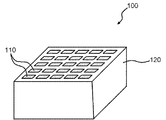
本発明の実施の一形態を図面を参照して以下に説明する。本実施の形態のシンチレータアレイ100は、放射線が入射すると内部で蛍光が発生する複数のシンチレータ結晶110を有するシンチレータアレイ100である。
An embodiment of the present invention will be described below with reference to the drawings. The
本実施の形態のシンチレータアレイ100は、PrがドープされたLu3Al5O12結晶で細長形状の複数のシンチレータ結晶110が形成されており、図1に示すように、複数のシンチレータ結晶110が長手方向と直交する方向に0.05mm以上0.2mm以下の間隙で二次元状に配列されており、配列された複数のシンチレータ結晶110の間隙にBaSO4を主成分とする反射材120が充填されている。
In the
この反射材120は、BaSO4の粉末(図示せず)が混入されていて複数のシンチレータ結晶110の間隙に充填されている樹脂からなる。BaSO4の粉末の平均粒径は、例えば、1μm以下である。反射材120の樹脂は、例えば、アクリル樹脂からなる。
The reflecting
本実施の形態のシンチレータアレイ100を製造するときには、例えば、細長形状の複数のシンチレータ結晶110を長手方向と直交する方向に二次元状に所定間隔で専用治具などで保持し、配列された複数のシンチレータ結晶110の間隙に反射材120となる樹脂と溶媒とを混合した混合液を充填し、この混合液から溶媒を減圧除去して反射材120を凝固させる(図示せず)。
When the
このようなアレイ製造方法によれば、複数のシンチレータ結晶110を二次元状に配列してから、間隙に充填した混合液を凝固させるので、複数のシンチレータ結晶110の位置精度が良好である。
According to such an array manufacturing method, since the plurality of
また、外側面に反射材を塗布したり反射テープを貼着した複数のシンチレータ結晶110をアレイ状に配列するような必要がなく、複数のシンチレータ結晶110を収納容器に圧入するような必要もなく、大型のシンチレータ結晶110を切削してシンチレータアレイ100を形成するような必要もない。
Further, it is not necessary to arrange a plurality of
このため、アレイ状に配列するシンチレータ結晶110の外側面を損傷するようなことがなく、シンチレータ結晶110の配列精度と検出精度とが良好なシンチレータアレイ100を簡単に製造することができる。
For this reason, the
しかも、混合液に反射材120の粉末を混入させておくので、複数のシンチレータ結晶110をアレイ状に固定すると同時に、複数のシンチレータ結晶110の外側面を反射面とすることができる。
In addition, since the powder of the
また、反射材120の粉末を含有する混合液は、反射材120の粉末と高分子系バインダと溶媒とを混合することにより、粘度を調節して流動性を確保することが容易である。しかも、反射材120のBaSO4の粉末の平均粒径が1μm以下であるので、シンチレータ結晶110の間隙に混合液を良好に充填することができる。
Moreover, the liquid mixture containing the powder of the
本実施の形態のシンチレータアレイ100では、PrがドープされたLu3Al5O12結晶からなるシンチレータ結晶110は、ガンマ線励起による発光量が従来のBGOに比較して三倍程度であり、かつ、減衰時間が22nsと短いので、例えば、TOF方式のPET用のシンチレータ結晶110として十分な特性を有する。
In the
また、このシンチレータ結晶110は、劈開性がないのでGSOより加工が容易であり、その融点はLSOより低く、線膨張係数の異方性がGSOやLSOに比べて小さく、単結晶成長も容易である。従って、良好な特性のシンチレータ結晶110を正確な形状に良好な生産性で量産することができる。
In addition, since this
さらに、PrがドープされたLu3Al5O12結晶からなるシンチレータ結晶110は、例えば、310nmの波長の蛍光を発生させるが、BaSO4を主成分とする反射材120は、300〜400nmの波長の蛍光を95%以上の反射率で反射する。
Further, the
このため、BaSO4を主成分とする反射材120は、PrがドープされたLu3Al5O12結晶からなるシンチレータ結晶110の蛍光を95%以上の反射率で反射することができる。
For this reason, the
BaSO4を主成分とする反射材120は0.05mm未満の層厚では均一に塗布することが困難である。さらに、BaSO4を主成分とする反射材120の層厚が0.2mmを超過しているとシンチレータアレイ100の分解能が極端に低下する。
It is difficult to apply the reflecting
しかし、本実施の形態のシンチレータアレイ100では、BaSO4を主成分とする反射材120が充填される複数のシンチレータ結晶110が0.05mm以上0.2mm以下の間隙で配列されているので、その間隙をBaSO4を主成分とする反射材120で良好に充填して良好な分解能を実現することができる。
However, in the
なお、BaSO4を主成分とする反射材120は、400nm以上の波長においても95%の反射率を有するので、400nm以上の発光波長を有するシンチレータ結晶(図示せず)にも使用可能である。
Note that the
ここで、本発明者による試作品の実験結果を実施例1〜3および比較例1〜3として以下に説明する。 Here, experimental results of prototypes by the present inventors will be described below as Examples 1 to 3 and Comparative Examples 1 to 3.
[実施例1]
2.1×2.1×15mmに研磨された、PrがドープされたLu3Al5O12結晶を12×12本組の正方形に組み、BaSO4を主成分とする反射材120を使用し、シンチレータアレイ100とした。反射材120の層厚は0.05mmとした。
[Example 1]
A
できたシンチレータアレイ100を位置敏感型PMT(Photomultiplier Tube)(浜松ホトニクス(登録商標)製H8500型)に光学グリスを使用して接着し、137Csからのガンマ線を照射して、各シンチレータ結晶110の発光量を測定したところ、ピークチャンネル数(発光量)は42chで分解能は12.5%であった。
The resulting
[実施例2]
2.1×2.1×15mmに研磨された、PrがドープされたLu3Al5O12結晶を12×12本組の正方形に組み、BaSO4を主成分とする反射材120を使用し、シンチレータアレイ100とした。反射材120の層厚は0.09mmとした。
[Example 2]
A
できたシンチレータアレイ100を位置敏感型PMT(浜松ホトニクス製H8500型)に光学グリスを使用して接着し、137Csからのガンマ線を照射して、各シンチレータ結晶110の発光量を測定したところ、ピークチャンネル数(発光量)は44chで分解能は12.0%であった。
The resulting
[実施例3]
2.1×2.1×15mmに研磨された、PrがドープされたLu3Al5O12結晶を12×12本組の正方形に組み、BaSO4を主成分とする反射材120を使用し、シンチレータアレイ100とした。反射材120の層厚は0.2mmとした。
[Example 3]
A
できたシンチレータアレイ100を位置敏感型PMT(浜松ホトニクス製H8500型)に光学グリスを使用して接着し、137Csからのガンマ線を照射して、各シンチレータ結晶110の発光量を測定したところ、ピークチャンネル数(発光量)は43chで分解能は12.2%であった。
The resulting
[比較例1]
2.1×2.1×15mmに研磨された、PrがドープされたLu3Al5O12結晶を12×12本組の正方形に組み、BaSO4を主成分とする反射材を使用し、シンチレータアレイとした。反射材の層厚は0.25mmとした。
[Comparative Example 1]
A Pr 3 -doped Lu 3 Al 5 O 12 crystal polished to 2.1 × 2.1 × 15 mm is assembled into 12 × 12 squares, and a reflective material mainly composed of BaSO 4 is used. A scintillator array was obtained. The layer thickness of the reflective material was 0.25 mm.
できたシンチレータアレイを位置敏感型PMT(浜松ホトニクス製H8500型)に光学グリスを使用して接着し、137Csからのガンマ線を照射して、各シンチレータ結晶の発光量を測定したところ、ピークチャンネル数(発光量)は28chで分解能は18.3%であった。 The resulting scintillator array was bonded to a position-sensitive PMT (H8500 type manufactured by Hamamatsu Photonics) using optical grease, and irradiated with gamma rays from 137 Cs, and the amount of light emitted from each scintillator crystal was measured. The (light emission amount) was 28 ch and the resolution was 18.3%.
[比較例2]
2.1×2.1×15mmに研磨された、PrがドープされたLu3Al5O12結晶を12×12本組の正方形に組み、BaSO4を主成分とする反射材を使用し、シンチレータアレイとした。反射材層厚は0.30mmとした。
[Comparative Example 2]
A Pr 3 -doped Lu 3 Al 5 O 12 crystal polished to 2.1 × 2.1 × 15 mm is assembled into 12 × 12 squares, and a reflective material mainly composed of BaSO 4 is used. A scintillator array was obtained. The reflector layer thickness was 0.30 mm.
できたシンチレータアレイを位置敏感型PMT(浜松ホトニクス製H8500型)に光学グリスを使用して接着し、137Csからのガンマ線を照射して、各シンチレータ結晶の発光量を測定したところ、ピークチャンネル数(発光量)は20chで分解能は20.5%であった。 The resulting scintillator array was bonded to a position-sensitive PMT (H8500 type manufactured by Hamamatsu Photonics) using optical grease, and irradiated with gamma rays from 137 Cs, and the amount of light emitted from each scintillator crystal was measured. The (light emission amount) was 20 ch and the resolution was 20.5%.
[比較例3]
2.1×2.1×15mmに研磨された、PrがドープされたLu3Al5O12結晶を12×12本組の正方形に組み、Al2O3を主成分とする反射材を使用し、シンチレータアレイとした。反射材層厚は0.12mmとした。
[Comparative Example 3]
A Pr 3 -doped Lu 3 Al 5 O 12 crystal polished to 2.1 x 2.1 x 15 mm is assembled into 12 x 12 squares, and a reflector composed mainly of Al 2 O 3 is used. The scintillator array was used. The reflector layer thickness was 0.12 mm.
できたシンチレータアレイを位置敏感型PMT(浜松ホトニクス製H8500型)に光学グリスを使用して接着し、137Csからのガンマ線を照射して、各シンチレータ結晶の発光量を測定したところ、ピークチャンネル数(発光量)は10chで分解能は35.2%であった。 The resulting scintillator array was bonded to a position-sensitive PMT (H8500 type manufactured by Hamamatsu Photonics) using optical grease, and irradiated with gamma rays from 137 Cs, and the amount of light emitted from each scintillator crystal was measured. The (light emission amount) was 10 ch and the resolution was 35.2%.
以上の実施例、比較例の結果を以下の表1にまとめた。

以上のように、BaSO4を主成分とする反射材120を使用した場合、反射材120の層厚が0.05mm〜0.2mmの範囲の発光量が高く、分解能も良いことが判明した。なお、BaSO4を主成分とする反射材の場合は、0.05mm未満の厚さでは均一に塗布することができないので、アレイ作製ができない。
As described above, it was found that when the
なお、本発明は本実施の形態に限定されるものではなく、その要旨を逸脱しない範囲で各種の変形を許容する。また、上述した実施例では、各部の構造などを具体的に説明したが、その構造などは本願発明を満足する範囲で各種に変更することができる。 The present invention is not limited to the present embodiment, and various modifications are allowed without departing from the scope of the present invention. In the above-described embodiments, the structure of each part has been specifically described. However, the structure and the like can be variously changed within a range that satisfies the present invention.
例えば、上記形態では反射材120の樹脂がアクリル樹脂からなることを例示した。しかし、反射材120の樹脂として、ポリビニルアルコール,シリコーン樹脂,エポキシ樹脂,これらの組み合わせ、等も利用することができる。
For example, in the said form, it illustrated that resin of the reflecting
100 シンチレータアレイ
110 シンチレータ結晶
120 反射材
100
Claims (1)
PrがドープされたLu3Al5O12結晶で細長形状の複数の前記シンチレータ結晶が形成されており、
複数の前記シンチレータ結晶が長手方向と直交する方向に0.05mm以上0.2mm以下の間隙で二次元状に配列されており、
配列された複数の前記シンチレータ結晶の間隙にBaSO4を主成分とする反射材が充填されていることを特徴とするシンチレータアレイ。 A scintillator array having a plurality of scintillator crystals that generate fluorescence inside when radiation is incident thereon,
Plural elongated scintillator crystals are formed of Pr 3 doped Lu 3 Al 5 O 12 crystal,
A plurality of scintillator crystals are arranged two-dimensionally with a gap of 0.05 mm or more and 0.2 mm or less in a direction orthogonal to the longitudinal direction,
A scintillator array, wherein a gap between the plurality of arranged scintillator crystals is filled with a reflective material mainly composed of BaSO 4 .
Priority Applications (1)
| Application Number | Priority Date | Filing Date | Title |
|---|---|---|---|
| JP2009262632A JP2011106981A (en) | 2009-11-18 | 2009-11-18 | Scintillator array |
Applications Claiming Priority (1)
| Application Number | Priority Date | Filing Date | Title |
|---|---|---|---|
| JP2009262632A JP2011106981A (en) | 2009-11-18 | 2009-11-18 | Scintillator array |
Publications (1)
| Publication Number | Publication Date |
|---|---|
| JP2011106981A true JP2011106981A (en) | 2011-06-02 |
Family
ID=44230625
Family Applications (1)
| Application Number | Title | Priority Date | Filing Date |
|---|---|---|---|
| JP2009262632A Pending JP2011106981A (en) | 2009-11-18 | 2009-11-18 | Scintillator array |
Country Status (1)
| Country | Link |
|---|---|
| JP (1) | JP2011106981A (en) |
Cited By (4)
| Publication number | Priority date | Publication date | Assignee | Title |
|---|---|---|---|---|
| CN103777225A (en) * | 2014-01-02 | 2014-05-07 | 苏州晶特晶体科技有限公司 | Radiography imaging detector scintillation crystal array and manufacture method thereof |
| CN103954989A (en) * | 2014-04-30 | 2014-07-30 | 苏州晶特晶体科技有限公司 | High-effect radiographing and imaging detector scintillation crystal array |
| KR20220145189A (en) * | 2021-04-21 | 2022-10-28 | 한양대학교 산학협력단 | Method and system for calibrating position-sensitive radiation detector |
| US12213820B2 (en) | 2020-01-17 | 2025-02-04 | The Research Foundation For The State University Of New York | High resolution and high sensitivity pet scanner with pet detector modules |
Citations (5)
| Publication number | Priority date | Publication date | Assignee | Title |
|---|---|---|---|---|
| JPH0519060A (en) * | 1991-07-10 | 1993-01-26 | Shin Etsu Chem Co Ltd | Scintillator manufacturing method |
| JPH10282244A (en) * | 1997-04-04 | 1998-10-23 | Hamamatsu Photonics Kk | Scintillator array |
| JP2009058453A (en) * | 2007-09-03 | 2009-03-19 | Tohoku Univ | Array manufacturing method, scintillator array |
| JP2009227794A (en) * | 2008-03-21 | 2009-10-08 | Hitachi Metals Ltd | Fluorescent material, its producing method and scintillator |
| JP2009264751A (en) * | 2008-04-21 | 2009-11-12 | Furukawa Co Ltd | Method for manufacturing of scintillator, the scintillator, application liquid for the scintillator, and method for preparing the liquid |
-
2009
- 2009-11-18 JP JP2009262632A patent/JP2011106981A/en active Pending
Patent Citations (5)
| Publication number | Priority date | Publication date | Assignee | Title |
|---|---|---|---|---|
| JPH0519060A (en) * | 1991-07-10 | 1993-01-26 | Shin Etsu Chem Co Ltd | Scintillator manufacturing method |
| JPH10282244A (en) * | 1997-04-04 | 1998-10-23 | Hamamatsu Photonics Kk | Scintillator array |
| JP2009058453A (en) * | 2007-09-03 | 2009-03-19 | Tohoku Univ | Array manufacturing method, scintillator array |
| JP2009227794A (en) * | 2008-03-21 | 2009-10-08 | Hitachi Metals Ltd | Fluorescent material, its producing method and scintillator |
| JP2009264751A (en) * | 2008-04-21 | 2009-11-12 | Furukawa Co Ltd | Method for manufacturing of scintillator, the scintillator, application liquid for the scintillator, and method for preparing the liquid |
Cited By (5)
| Publication number | Priority date | Publication date | Assignee | Title |
|---|---|---|---|---|
| CN103777225A (en) * | 2014-01-02 | 2014-05-07 | 苏州晶特晶体科技有限公司 | Radiography imaging detector scintillation crystal array and manufacture method thereof |
| CN103954989A (en) * | 2014-04-30 | 2014-07-30 | 苏州晶特晶体科技有限公司 | High-effect radiographing and imaging detector scintillation crystal array |
| US12213820B2 (en) | 2020-01-17 | 2025-02-04 | The Research Foundation For The State University Of New York | High resolution and high sensitivity pet scanner with pet detector modules |
| KR20220145189A (en) * | 2021-04-21 | 2022-10-28 | 한양대학교 산학협력단 | Method and system for calibrating position-sensitive radiation detector |
| KR102604818B1 (en) * | 2021-04-21 | 2023-11-20 | 한양대학교 산학협력단 | Method and system for calibrating position-sensitive radiation detector |
Similar Documents
| Publication | Publication Date | Title |
|---|---|---|
| US7304309B2 (en) | Radiation detectors | |
| RU2487373C2 (en) | Radiation-sensitive detector with scintillator in composite resin | |
| US6784432B2 (en) | X-ray detector module | |
| JP6113662B2 (en) | Scintillator array and X-ray detector and X-ray inspection apparatus using the same | |
| CN107924731B (en) | Ceramic scintillator array and its manufacturing method, radiation detector, and radiation inspection apparatus | |
| US8618489B2 (en) | Scintillator crystal having phase-separated structure | |
| US8344328B2 (en) | Three-dimensional radiation position detector | |
| CN105190358A (en) | Large-area scintillator element and radiation detectors and radiation absorption event locating systems using same | |
| JPWO2015052977A1 (en) | Radiation detector and method for manufacturing radiation detector | |
| US20180172846A1 (en) | High-Performance Composite Scintillator | |
| Wilson et al. | Optimisation of monolithic nanocomposite and transparent ceramic scintillation detectors for positron emission tomography | |
| JP5080910B2 (en) | Array manufacturing method, scintillator array | |
| JP2011106981A (en) | Scintillator array | |
| US20210324217A1 (en) | Optically transparent 3d printed polysiloxane scintillators | |
| JP5854128B2 (en) | Manufacturing method of scintillator dual array | |
| US20110056618A1 (en) | Method of manufacturing radiation detector | |
| CN104781692A (en) | Digital radiography detector | |
| US20250180761A1 (en) | Scintillation crystal array, detector, medical imaging device, and manufacturing method | |
| JP2011232197A (en) | Scintillator panel and radiation image detection device | |
| Yoshida et al. | Intrinsic spatial resolution evaluation of the X’tal cube PET detector based on a 3D crystal block segmented by laser processing | |
| JP7310015B2 (en) | Hybrid laser/air coupled PET block detector | |
| Kronberger | Optimization of the light extraction from heavy inorganic scintillators | |
| US7282714B2 (en) | Moldable and curing reflector material with high reflectivity | |
| Raylman et al. | Evaluation of advanced methods and materials for construction of scintillation detector light guides | |
| RU2711219C1 (en) | Method of making reflecting surfaces for scintillation elements |
Legal Events
| Date | Code | Title | Description |
|---|---|---|---|
| A621 | Written request for application examination |
Free format text: JAPANESE INTERMEDIATE CODE: A621 Effective date: 20120905 |
|
| A977 | Report on retrieval |
Free format text: JAPANESE INTERMEDIATE CODE: A971007 Effective date: 20130322 |
|
| A131 | Notification of reasons for refusal |
Free format text: JAPANESE INTERMEDIATE CODE: A131 Effective date: 20130326 |
|
| A02 | Decision of refusal |
Free format text: JAPANESE INTERMEDIATE CODE: A02 Effective date: 20130730 |