JP2011106918A - Method and system for calculating heat conductivity - Google Patents
Method and system for calculating heat conductivity Download PDFInfo
- Publication number
- JP2011106918A JP2011106918A JP2009261001A JP2009261001A JP2011106918A JP 2011106918 A JP2011106918 A JP 2011106918A JP 2009261001 A JP2009261001 A JP 2009261001A JP 2009261001 A JP2009261001 A JP 2009261001A JP 2011106918 A JP2011106918 A JP 2011106918A
- Authority
- JP
- Japan
- Prior art keywords
- thermal conductivity
- temperature
- measurement
- measurement sample
- calculating
- Prior art date
- Legal status (The legal status is an assumption and is not a legal conclusion. Google has not performed a legal analysis and makes no representation as to the accuracy of the status listed.)
- Withdrawn
Links
Images

Landscapes
- Investigating Or Analyzing Materials Using Thermal Means (AREA)
Abstract
【課題】簡易な構成により未知の熱伝導率を精度良く得る技術を提供する。
【解決手段】測定対象の熱伝導率の仮の値を変化させてシミュレーションした結果と、実測結果とから、測定対象の熱伝導率を算出する。このとき実測環境をシンプルなものとし、シミュレーションでその環境を再現しやすくする。シンプルな実測環境として、対流、放射の影響を抑え、伝導のみが支配的なものとする。また、温度差を用いることにより、シミュレーション時に設定する境界条件の誤差をキャンセルし、シミュレーションの精度をさらに高める。
【選択図】図4A technique for accurately obtaining unknown thermal conductivity with a simple configuration is provided.
A thermal conductivity of a measurement target is calculated from a simulation result obtained by changing a temporary value of the thermal conductivity of the measurement target and an actual measurement result. At this time, the actual measurement environment is simplified, and the environment is easily reproduced by simulation. As a simple measurement environment, the influence of convection and radiation is suppressed and only conduction is dominant. Further, by using the temperature difference, the error of the boundary condition set during the simulation is canceled, and the simulation accuracy is further improved.
[Selection] Figure 4
Description
本発明は、物体の未知の熱伝導率を算出する技術に関する。 The present invention relates to a technique for calculating an unknown thermal conductivity of an object.
電気製品や電子機器の複雑化、小型化に伴い、構成部品の放熱等を考慮した熱設計が重要になっている。製品内部の気流や熱などの熱流体現象を解析するにあたり、個々の構成部品の正確な熱物性値を得ることは非常に重要である。熱物性値の中でも、特に、温度に寄与する熱伝導率の把握は重要視されている。 With the increasing complexity and miniaturization of electrical products and electronic equipment, thermal design that takes heat dissipation of components into account is becoming important. It is very important to obtain accurate thermophysical values of individual components when analyzing thermal fluid phenomena such as airflow and heat inside products. Among thermophysical values, in particular, grasping the thermal conductivity that contributes to temperature is regarded as important.
一般に、物体の熱伝導率を測定するためには、断熱体で覆ったヒータ、熱伝導率を測定する対象の物体(測定サンプル)、および熱伝導率が既知の物体(既知サンプル)、を重ね、それぞれの間に熱電対を取り付け、熱電対の出力を用いて算出する手法が用いられる(例えば、特許文献1参照。)。 In general, in order to measure the thermal conductivity of an object, a heater covered with a heat insulator, an object to be measured for thermal conductivity (measurement sample), and an object with a known thermal conductivity (known sample) are stacked. A method is used in which a thermocouple is attached between the two and calculation is performed using the output of the thermocouple (see, for example, Patent Document 1).
ところが、この手法を実現する装置は非常に高価である。例えば、0.01〜50W/mK程度の熱伝導率が低い物体の測定では、この手法の中でも熱線プローブ法やホットディスク法が用いられる。これを実現する装置の価格は約数百万円である。また、400W/mK以上といった熱伝導率の高い物体の測定ではレーザーフラッシュ法が用いられる。これを実現する装置の価格は数千万円である。 However, an apparatus that realizes this technique is very expensive. For example, in the measurement of an object having a low thermal conductivity of about 0.01 to 50 W / mK, the hot wire probe method and the hot disk method are used among these methods. The price of a device that realizes this is about several million yen. A laser flash method is used for measuring an object having a high thermal conductivity of 400 W / mK or more. The price of a device that realizes this is tens of millions of yen.
熱設計では、物体の一部に発熱体(ヒータ)を取り付けて加熱した場合の物体内の熱分布を計算する熱流体解析ソフトウェアが利用されている。良く知られているものに、例えば、FLUENT(登録商標)やCFdesign(登録商標)などがある。これらの熱流体解析ソフトウェアに、ヒータ電力、ケース外空気などの境界条件と、物体の熱物性値(熱伝導率、放射率、密度など)とを入力し、シミュレーションを行うことで、物体の熱分布、すなわち、物体各部の温度を得ることができる。 In thermal design, thermal fluid analysis software is used to calculate the heat distribution in an object when a heating element (heater) is attached to a part of the object and heated. Well-known ones include, for example, FLUENT (registered trademark) and CFdesign (registered trademark). By inputting boundary conditions such as heater power and air outside the case and the thermal properties of the object (thermal conductivity, emissivity, density, etc.) into these thermal fluid analysis software, and performing simulation, The distribution, that is, the temperature of each part of the object can be obtained.
実測した物体の温度と、熱流体解析ソフトウェアによるシミュレーション結果とのフィッティングにより、熱伝導率等の物性値を、高価な測定装置を使用することなく求めることが考えられるが、求められる物性値の信頼性を向上させることは困難であった。その原因は、精度よく物体の温度を測定できたとしても、熱流体解析ソフトウェアで用いる境界条件などを正確に入力することが困難であり、測定状態を精度よく再現してシミュレーションすることが難しいためであると考えられる。 It is conceivable that physical properties such as thermal conductivity can be obtained without using an expensive measuring device by fitting the measured temperature of the object with the simulation results of the thermal fluid analysis software. It was difficult to improve the performance. The reason is that even if the temperature of the object can be measured accurately, it is difficult to accurately input the boundary conditions used in the thermal fluid analysis software, and it is difficult to accurately reproduce and simulate the measurement state. It is thought that.
本発明は、上記事情に鑑みてなされたもので、簡易な構成により未知の熱伝導率を精度良く得る技術を提供することを目的とする。 The present invention has been made in view of the above circumstances, and an object thereof is to provide a technique for accurately obtaining unknown thermal conductivity with a simple configuration.
本発明は、測定対象の熱伝導率の仮の値を変化させてシミュレーションして得た温度と、実測温度とから、測定対象の熱伝導率を決定する。このとき、実測環境をシンプルなものとし、シミュレーションでその環境を再現しやすくし、実測温度とシミュレーションにより得た温度との整合性を高める。 In the present invention, the thermal conductivity of the measurement target is determined from the temperature obtained by simulation by changing the temporary value of the thermal conductivity of the measurement target, and the actually measured temperature. At this time, the actual measurement environment is simplified, the environment is easily reproduced by simulation, and the consistency between the actual measurement temperature and the temperature obtained by the simulation is enhanced.
具体的には、測定サンプルの熱伝導率を算出する熱伝導率算出方法であって、前記測定サンプルに熱を供給する発熱体に投入する電力を決定する投入電力決定ステップと、前記発熱体に前記投入電力を投入して発熱させた際の前記測定サンプルの温度を、予め定めた測定点において測定し、実測温度を得る温度測定ステップと、予め定められた複数の熱伝導率設定値それぞれに対応する前記測定サンプルの温度を推定温度として算出する温度推定ステップと、前記複数の熱伝導率設定値毎の前記推定温度から熱伝導率と推定温度とを関連付ける近似関数を決定する近似関数算出ステップと、前記近似関数上で、前記実測温度を用い、当該測定サンプルの熱伝導率を算出する熱伝導率算出ステップと、を備えることを特徴とする熱伝導率算出方法を提供する。 Specifically, a thermal conductivity calculation method for calculating the thermal conductivity of a measurement sample, the input power determination step for determining the power to be input to a heating element that supplies heat to the measurement sample, and the heating element The temperature of the measurement sample when the input power is turned on to generate heat is measured at a predetermined measurement point, and a temperature measurement step for obtaining an actual temperature, and a plurality of predetermined thermal conductivity setting values, respectively. A temperature estimation step for calculating the temperature of the corresponding measurement sample as an estimated temperature, and an approximate function calculation step for determining an approximate function for associating the thermal conductivity with the estimated temperature from the estimated temperature for each of the plurality of thermal conductivity setting values And a thermal conductivity calculation step for calculating the thermal conductivity of the measurement sample using the measured temperature on the approximate function, and a thermal conductivity calculation method comprising: To provide.
また、測定サンプルの未知の熱伝導率を算出する熱伝導率算出システムであって、前記測定サンプルに熱を供給する発熱体に投入する投入電力を決定する投入電力決定手段と前記発熱体に前記電力を投入して発熱させた際の前記測定サンプルの温度を、予め定めた測定点において測定し、実測温度を得る温度測定手段と、予め定められた複数の熱伝導率設定値それぞれに対応する前記測定サンプルの温度を推定温度として算出する温度推定手段と、前記複数の熱伝導率設定値毎の前記推定温度から熱伝導率と推定温度とを関連付ける近似関数を決定する近似関数算出手段と、前記近似関数上で、前記実測温度を用い、当該測定サンプルの熱伝導率を算出する熱伝導率算出手段と、を備えることを特徴とする熱伝導率算出システムを提供する。 Further, a thermal conductivity calculation system for calculating an unknown thermal conductivity of a measurement sample, the input power determining means for determining input power to be input to a heating element that supplies heat to the measurement sample, and the heating element The temperature of the measurement sample when heated to generate heat is measured at a predetermined measurement point and corresponds to each of a plurality of predetermined thermal conductivity setting values and temperature measurement means for obtaining an actual measurement temperature. Temperature estimation means for calculating the temperature of the measurement sample as an estimated temperature; and approximate function calculation means for determining an approximate function that associates thermal conductivity with the estimated temperature from the estimated temperature for each of the plurality of thermal conductivity setting values; There is provided a thermal conductivity calculation system comprising: thermal conductivity calculation means for calculating the thermal conductivity of the measurement sample using the measured temperature on the approximate function.
本発明によれば、簡易な構成により未知の熱伝導率を精度良く得ることができる。 According to the present invention, an unknown thermal conductivity can be obtained with high accuracy by a simple configuration.
<<第一の実施形態>>
以下、本発明を適用する第一の実施形態について説明する。本発明の実施形態を説明するための全図において、同一機能を有するものは同一符号を付し、その繰り返しの説明は省略する。
<< First Embodiment >>
Hereinafter, a first embodiment to which the present invention is applied will be described. In all the drawings for explaining the embodiments of the present invention, those having the same function are denoted by the same reference numerals, and repeated explanation thereof is omitted.
本実施形態の熱伝導率算出システムでは、実測値と熱流体解析ソフトウェアによるシミュレーション結果とから、測定対象物体(測定サンプル)の所望の熱伝導率を求める。なお、測定サンプルは、導電体、絶縁体などとする。 In the thermal conductivity calculation system of the present embodiment, the desired thermal conductivity of the measurement target object (measurement sample) is obtained from the actual measurement value and the simulation result by the thermal fluid analysis software. Note that the measurement sample is a conductor, an insulator, or the like.
従来、熱流体解析ソフトウェアでのシミュレーション値と実測値との整合性は低いことが知られている。これは、前述のように境界条件の入力が難しく、それに影響を受ける対流、放射の影響を再現することが難しいためである。さらに、演算されるパラメータの中で、対流・放射のパラメータは、オペレーションで設定したメッシュサイズにより変化する。その結果、対流・放射の影響が大きい環境では、最終的に見積もられる温度結果がメッシュサイズにより異なるという、メッシュサイズによる算出誤差も発生する。なお、メッシュサイズを細かくすると精度は高まるが、計算時間とのトレードオフ関係にあるため、極端に細かくすることは現実的ではない。また、ある一定のメッシュサイズでは、発熱量が大きくなるとともに対流と反射とが促進されるため、対流・放射のパラメータが算出結果に及ぼす影響が大きくなり、精度は悪化する。換言すると、適切なメッシュサイズであれば、発熱量が小さいほど実測との差異は小さくできる。熱伝導率推定において、熱流体解析結果と実測の差異は小さい方が望ましい。従って、精度を高めるような最小の発熱量で実測と熱流体解析を実施すればよい。そこで、本実施形態では、最小の発熱量で熱流体解析ソフトウェアを用いたシミュレーションを行い、求めたシミュレーション結果と実測値とから熱伝導率を精度よく求める。 Conventionally, it is known that the consistency between the simulation value and the actual measurement value in the thermal fluid analysis software is low. This is because it is difficult to input boundary conditions as described above, and it is difficult to reproduce the influence of convection and radiation affected by the boundary conditions. Further, among the calculated parameters, the convection / radiation parameters vary depending on the mesh size set in the operation. As a result, in an environment where the influence of convection / radiation is large, a calculation error due to the mesh size also occurs, in which the finally estimated temperature result varies depending on the mesh size. If the mesh size is made finer, the accuracy is improved, but since it is in a trade-off relationship with the calculation time, it is not realistic to make it extremely finer. In addition, with a certain mesh size, the amount of heat generation increases, and convection and reflection are promoted. Therefore, the influence of convection / radiation parameters on the calculation result increases, and the accuracy deteriorates. In other words, if the mesh size is appropriate, the difference from the actual measurement can be reduced as the calorific value is reduced. In the thermal conductivity estimation, it is desirable that the difference between the thermal fluid analysis result and the actual measurement is small. Therefore, it is only necessary to perform actual measurement and thermal fluid analysis with a minimum calorific value to improve accuracy. Therefore, in the present embodiment, a simulation using the thermal fluid analysis software is performed with the minimum calorific value, and the thermal conductivity is accurately obtained from the obtained simulation result and the actually measured value.
具体的には、後述する図4の投入電力決定処理において、熱伝導率算出にあたり、熱移動のうち、対流・放射の影響が少なく伝導が支配的となる条件を実現するものとして、測定サンプル上で温度差が生じる発熱量の中で最小の発熱量を実現する投入電力を決定する。求めた条件で、実測およびシミュレーション(熱流体解析処理)をそれぞれ行い、実測値に一致するシミュレーション条件を測定対象の熱伝導率とする。 Specifically, in the input power determination process of FIG. 4 to be described later, in calculating the thermal conductivity, it is assumed that a condition in which conduction is dominant with less influence of convection / radiation is realized in the heat sample. The input power that realizes the minimum heat generation amount among the heat generation amounts that cause a temperature difference is determined. Under the obtained conditions, actual measurement and simulation (thermal fluid analysis processing) are performed, and the simulation condition that matches the actual measurement value is set as the thermal conductivity of the measurement target.
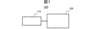
まず、本実施形態の熱伝導率算出システム全体の構成について説明する。図1は、本実施形態の熱伝導率算出システム100の構成図である。本図に示すように、本実施形態の熱伝導率算出システム100は、温度測定装置110と熱伝導率算出装置120とを備える。温度測定装置110は、熱伝導率算出装置120からの指示に従って、測定サンプルの表面温度を測定する。熱伝導率算出装置120は、温度測定装置110による測定結果と予め保持する熱流体解析ソフトウェアを用いたシミュレーション結果とから、熱伝導率を算出する熱伝導率算出処理を行う。
First, the structure of the whole thermal conductivity calculation system of this embodiment is demonstrated. FIG. 1 is a configuration diagram of a thermal
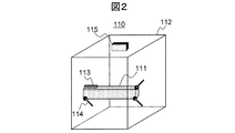
図2は、本実施形態の温度測定装置110を説明するための図である。本図に示すように、温度測定装置110は、内部に測定サンプル111を設置する樹脂ケース112と、測定サンプル111を熱するヒータ113と、測定サンプル111に接触させてその温度を測定する熱電対114と、非接触でその放射エネルギー量を検知することで測定サンプル111表面の温度を測定する放射温度計115と、を備える。
FIG. 2 is a diagram for explaining the
ここで、放射温度計115は、測定サンプル111と対向して少なくとも1つ以上設置される。設置場所は、ヒータ113などの発熱体からの放射エネルギーの影響を受けない部分に設置することが好ましい。具体的には、例えば、ヒートシンクを測定する場合には熱源から離れたフィン部を測定する。
Here, at least one radiation thermometer 115 is installed to face the
本実施形態の温度測定装置110は、熱伝導率算出装置120から指示された電力をヒータ113に投入し、熱伝導率算出装置120で指示された測定点の温度を熱電対114および/または放射温度計115で計測し、熱伝導率算出装置120に出力する。
The
ヒータ113は、熱伝導グリスやシートなどのTIM(Thermal Interface Material)を介して測定サンプル111に取り付けられる。
The
また、熱電対114は、少なくとも、予め定められた測定サンプル111上の温度を測定する測定点に設置される。
Further, the
放射温度計115は、少なくとも、熱電対114による各測定点の近傍に設置される。放射温度計115は、熱流体解析ソフトウェアでシミュレーションを行う際のパラメータとしての放射率を求めるために用いる。熱電対114や熱電対114を固定するテープなどは、放射温度計115による温度計測の誤差要因となるため、測定箇所は、測定サンプル111の表面であって、これらを含まない領域とする。従って、放射温度計115は、その測定範囲をレーザポインタで認識できる構成が望ましい。
The radiation thermometer 115 is installed at least in the vicinity of each measurement point by the
樹脂ケース112は、温度測定時に外乱の影響を受けないように設けられる。用いる樹脂には、熱伝導率が低い絶縁部材、例えば、アクリルやポリカーボネートなどが選択される。なお、樹脂ケース112の大きさは、対流と放射との影響を小さくするために測定の際の発熱により樹脂ケース112内の空気温度が大きく上昇しない程度とする。
The
図3は、本実施形態の熱伝導率算出装置120の機能ブロック図である。本図に示すように、本実施形態の熱伝導率算出装置120は、実測した温度と熱流体解析実測値と熱流体解析ソフトウェアによるシミュレーション値とから熱伝導率を求める。これを実現するため、熱伝導率算出装置120は、ヒータ113を所望の発熱量で発熱させるためにヒータ113に投入する投入電力を決定する投入電力決定部210と、温度測定装置110を動作させて測定サンプル111の所定の温度測定点の温度を計測するとともにシミュレーションに必要なパラメータを算出するパラメータ決定部220と、予め用意される熱伝導率の仮設定値毎に熱流体解析ソフトウェアを用いてシミュレーションを行い、温度測定点の温度を推定する熱流体解析を行う熱流体解析部230と、熱流体解析結果から熱伝導率と温度との関係を特定する近似関数を作成する近似関数作成部240と、近似関数から熱伝導率を算出する熱伝導率算出部250と、温度測定装置110から測定値を受け取り保持する測定値保持部310と、シミュレーションの際に用いる測定対象の未知の熱伝導率の仮設定値を保持する仮設定値保持部320と、を備える。ここでは、仮設定値保持部320には、熱伝導率の仮設定値(熱伝導率設定値)として、予め入力された複数の異なる値が、それぞれ一意に特定可能な識別情報とともに保持される。
FIG. 3 is a functional block diagram of the thermal
熱伝導率算出装置120は、例えば、CPUとメモリと記憶装置とを備える汎用の情報処理装置で構成される。投入電力決定部210とパラメータ決定部220と熱流体解析部230と近似関数作成部240と熱伝導率算出部250とは、記憶装置に格納されるプログラムをCPUがメモリにロードして実行することにより実現される。また、測定値保持部310と仮設定値保持部320とは、記憶装置に構成される。なお、熱伝導率算出システム100による熱伝導率算出処理の途中に生成される各種の中間データも、記憶装置に記憶される。
The thermal
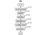
本実施形態の熱伝導率算出システム100による熱伝導率算出処理の流れを説明する。図4は、本実施形態の熱伝導率算出処理の処理フローである。
The flow of thermal conductivity calculation processing by the thermal
ユーザから開始の指示を受け付けると、まず、投入電力決定部210が、測定サンプル111の温度を測定する際のヒータ113への投入電力を決定する投入電力決定処理を行う(ステップS1101)。これにより、上述したように対流・放射の影響の少ない、伝導が支配的となるヒータ発熱量を実現する投入電力を求める。また、このヒータ発熱量は、後述する熱流体解析に用いる。
When a start instruction is received from the user, first, the input
次に、パラメータ決定部220は、温度測定装置110に、ステップS1101で決定した投入電力をヒータ113に投入させ、熱電対114により、測定サンプル111の予め定められた測定点(温度測定点)の温度を測定させる(ステップS1102)。次に、放射温度計115で測定した測定点の温度が熱電対114で測定した温度と同じになるように、放射温度計に入力する放射率を変化させることにより、温度測定点の放射率を求める(ステップS1103)。本実施形態では、温度測定点は1点とする。温度測定点は、発熱源であるヒータ113の近傍とする。発熱源近傍は、対流や放射の影響が少なく、シミュレーションでその環境を再現しやすいためである。なお、パラメータ決定部220は、測定した温度を測定点に対応づけて測定値保持部310に記憶する。また、算出した放射率、ステップS1101で決定した投入電力(発熱量)も測定値保持部310に記憶する。
Next, the
次に、熱流体解析部230は、予め記憶装置に保持する熱流体解析ソフトウェアを用いて熱流体解析処理を行う(ステップS1104)。このとき、入力パラメータのうち、発熱量、放射率については、測定値保持部310に保持するデータを、熱伝導率については、仮設定値保持部320に保持する複数の熱伝導率設定値を用いる。
Next, the thermal
次に、近似関数作成部240は、熱流体解析結果を用い、熱伝導率と温度との関係を示す関数の近似式を決定し、近似関数を生成する(近似関数生成処理:ステップS1105)。そして、熱伝導率算出部250は、近似関数にステップS1102で実測した温度を代入することにより、測定サンプル111の熱伝導率を求め(ステップS1106)、処理を終了する。
Next, the approximate
以下、各処理の詳細について説明する。 Details of each process will be described below.
まず、ステップS1101の、投入電力決定部210による投入電力決定処理を説明する。投入電力決定部210は、温度測定装置110を用いて温度を実測しながら投入電力を決定する。
First, input power determination processing by the input
前述したように、熱流体解析ソフトウェアを用いて算出する温度(推定温度)の精度を向上させることは難しい。これは、熱流体解析では伝導、対流、放射といった、複数の異なる形態の熱移動を扱い、現象が複雑になっていることが一因である。これらの熱移動の要因の中で、1の要因が支配的となるような環境において実測を行うことにより、モデル化する環境を単純化し、シミュレーションでその環境を再現しやすいものとする。 As described above, it is difficult to improve the accuracy of the temperature (estimated temperature) calculated using the thermal fluid analysis software. One reason for this is that the thermal fluid analysis deals with a plurality of different forms of heat transfer such as conduction, convection, and radiation, and the phenomenon is complicated. By performing actual measurement in an environment in which one of the factors of heat transfer is dominant, the environment to be modeled is simplified and the environment can be easily reproduced by simulation.
本実施形態では、対流や放射の影響が少なく、伝導が支配的となる環境下で実測を行う。このような環境は、できるだけヒータ113の発熱量を小さくし、かつ、測定サンプル111上の2つの測定点間には測定可能な程度の温度差が生じるようにすることで実現できる。ヒータ113の発熱量を小さくすることにより、測定サンプル111において対流と放射との影響を少なくできるためである。また、測定点間に測定可能な温度差が生じるようにすることで、測定サンプル111における伝導の影響を確認できる。本実施形態では、測定サンプル111の2つの測定点間の温度差が所定以下(例えば、10℃以下)となる投入電力を求める。適切な温度差は測定サンプル111の大きさ、素材等によって異なり、例えば、100mm角1mm厚の銅平板では、2℃である。
In the present embodiment, measurement is performed in an environment where conduction is dominant with little influence of convection and radiation. Such an environment can be realized by making the heat generation amount of the
なお、投入電力決定処理の測定点は、少なくとも2点を設定する。一方の測定点(第一の測定点)は、ヒータ113近傍の位置に、他方の測定点(第二の測定点)は、第一の測定点から、熱伝導による等軸上で出来うる限り距離をおいて設置する。これは、温度差がない(2点間の温度差が0℃となる)場合、熱伝導率算出の計算が発散し、解が求められないためである。なお、測定点を3点以上設定する場合は、両端の2点について、この条件を満たすよう設定し、残りの点については、その間に等間隔に設定する。
Note that at least two measurement points are set for the input power determination process. One measurement point (first measurement point) is at a position near the
また、測定は、常温・常圧下で行い、ヒータ113の電力を投入後、測定サンプル111と樹脂ケース112内の空気温度とが定常状態に達してから行う。
The measurement is performed at normal temperature and normal pressure, and after the
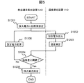
図5は、本実施形態の投入電力決定処理の処理フローである。ここでは、測定点として2点設定する場合を例にあげて説明する。また、初期電力(PW0)と、投入する電力(PW)の変化量(ΔPW)と、温度差の有無の判定に用いる閾値ΔT0と、は予め定められ、記憶装置に保持される。 FIG. 5 is a processing flow of input power determination processing according to the present embodiment. Here, a case where two measurement points are set will be described as an example. The initial power (PW0), the amount of change (ΔPW) in the input power (PW), and the threshold value ΔT0 used to determine whether there is a temperature difference are determined in advance and stored in the storage device.
まず、投入電力決定部210は、ヒータ113に投入する電力(PW)として初期電力(PW0)を設定し、当該電力を投入するよう温度測定装置110に指示を出す(ステップS1201)。それを受けて、温度測定装置110では、投入電力(PW)に初期電力(PW0)を設定し、測定サンプル111を熱する(ステップS1202)。そして、温度測定装置110では、設定した測定点2点の温度を測定する(ステップS1203)。測定点は、上記条件に従って設定される。また、温度の測定は、熱電対114による接触法、放射温度計115による非接触法のいずれであってもよい。また、この他の手法を用いてもよい。
First, the input
温度測定装置110から測定結果を受け取ると、投入電力決定部210は、2点の測定結果間に所定の温度差(ΔT0)が発生したか否かを判別する(ステップS1204)。ここでは、両測定点間の温度差ΔTが閾値ΔT0以上の場合、温度差が発生したと判別する。温度差が発生したと判別された場合、その時点で設定されている電力(PW)を、投入電力と決定する(ステップS1205)。なお、ヒータ113は温度によって内部抵抗が変動するため、時間の経過に伴い、滑らかに消費電力は下がる。従って、後述する熱流体解析処理に用いる発熱量は、ヒータ113の消費電力が十分低下した後の最終電力値を用いる。
When receiving the measurement result from the
一方、ステップS1204において、両測定点間に温度差が発生していないと判別された場合、電力PWを、予め定めた変化量(ΔPW)増加させ(ステップS1206)、ステップS1202に戻る。 On the other hand, if it is determined in step S1204 that there is no temperature difference between the two measurement points, the power PW is increased by a predetermined change amount (ΔPW) (step S1206), and the process returns to step S1202.
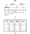
以上の手順で投入電力を決定する具体例を図6に示す。図6(a)は、測定点の位置を説明するための図である。ここでは、測定サンプル111が、100mm角1mm厚の銅平板で、測定点11(第一の測定点)が、ヒータ113が設置される端部から20mmの位置に設置され、測定点12(第二の測定点)が、同端部から80mmの位置に設置される。初期電力PW0は0.5W、変化量ΔPWは0.5W、温度差の有無の判定に用いる閾値ΔT0は2℃とする。
A specific example of determining the input power by the above procedure is shown in FIG. FIG. 6A is a diagram for explaining the positions of measurement points. Here, the
図6(b)は、投入電力決定処理実行中の温度測定結果を示す。本図に示す結果から、上記条件では、電力PWを、0.5Wから0.5W刻みで上昇させると、2Wの時点で測定点11と測定点12との温度差ΔTが閾値である2℃に達する。従って、この場合、投入電力を、2Wと決定する。 FIG. 6B shows a temperature measurement result during execution of the input power determination process. From the results shown in this figure, under the above conditions, when the power PW is increased from 0.5 W in increments of 0.5 W, the temperature difference ΔT between the measurement point 11 and the measurement point 12 at the time of 2 W is 2 ° C. To reach. Therefore, in this case, the input power is determined to be 2W.
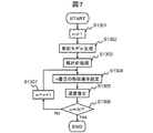
次に、上記熱伝導率算出処理のステップS1104の熱流体解析部230による熱流体解析処理を説明する。図7は、熱流体解析処理の処理フローである。
Next, the thermal fluid analysis process by the thermal
ここでは、市販の熱流体解析ソフト(例えば、FLUENT(登録商標)、CFdesign(登録商標))などを用いて行う。また、仮設定値保持部320には、熱伝導率設定値として、文献値・公表値などを参考に決定する概略値と、当該概略値を基準に、その±30%、±60%等正負同じ幅で変化させた、少なくとも3つ、好ましくは5つ以上の異なる値を保持する。ここでは、N個(Nは3以上の自然数)の異なる熱伝導率設定値が、1からNまでの番号に対応づけて保持されているものとする。なお、熱伝導率の変化に対し温度変化が大きくなる領域(凡そ100[W/(m・K)]以下)では、さらに保持する熱伝導率の値を追加してもよい。
Here, commercially available thermal fluid analysis software (for example, FLUENT (registered trademark), CFdesign (registered trademark)) or the like is used. In addition, the temporary set
熱流体解析処理開始の指示を受け付けると、熱流体解析部230は、まず、カウンタnを1とする(ステップS1301)。熱流体解析に必要なヒータ113、TIM、測定サンプル111、樹脂ケース112、樹脂ケース112内空気、樹脂ケース112外空気を3次元CADによりモデリングし、解析モデルを生成する(ステップS1302)。
When receiving the instruction to start the thermal fluid analysis process, the thermal
この際、解析結果と実測温度との差異が大きくならない程度に、測定した状態を再現しておく。これは、実際の温度測定環境とシミュレーションに用いる環境とを一致させることを意味する。具体的な手順としては、まず、実際の温度測定において、外乱の影響を受けないように、測定サンプル111を樹脂ケース112に入れて測定する。ここで、外乱としては、空気の対流や他の熱源からの放射が挙げられる。そして、シミュレーションでも、モデリングや条件設定を行って、その算出時に用いる環境として上記実測環境を再現する。
At this time, the measured state is reproduced so that the difference between the analysis result and the actually measured temperature does not increase. This means that the actual temperature measurement environment and the environment used for the simulation are matched. As a specific procedure, first, in the actual temperature measurement, the
次に、解析前処理を行う(ステップS1303)。解析前処理として、ここでは、解析モデルで特定される解析空間を分割するメッシュを生成し、熱流体解析ソフトウェアに設定する。また、樹脂ケース112外の空気温度、ステップS1101で算出したヒータ113の発熱量等の境界条件と、ステップS1103で算出した放射率、密度など、熱伝導率以外の熱伝導率とを熱流体解析ソフトに設定する。密度等は、予め入力し、記憶装置に保持しておく。
Next, pre-analysis processing is performed (step S1303). Here, as pre-analysis processing, a mesh that divides the analysis space specified by the analysis model is generated and set in the thermal fluid analysis software. Further, the thermal fluid analysis is performed on the boundary conditions such as the air temperature outside the
次に、熱伝導率を熱流体解析ソフトウェアの熱伝導率に設定する(ステップS1304)。ここでは、仮設定値保持部320に保持されている、n番目の熱伝導率設定値を設定する。
Next, the thermal conductivity is set to the thermal conductivity of the thermal fluid analysis software (step S1304). Here, the nth thermal conductivity set value held in the temporary set
そして、熱流体解析ソフトを用い、温度測定点の温度をシミュレーションにより算出する(ステップS1305)。なお、算出した温度は、推定温度として、ステップS1304で設定した熱伝導率設定値に対応づけて記憶装置に記憶する。 Then, the temperature of the temperature measurement point is calculated by simulation using thermal fluid analysis software (step S1305). The calculated temperature is stored in the storage device as the estimated temperature in association with the thermal conductivity setting value set in step S1304.
全ての熱伝導率設定値について処理を終えたか判別し(n=N?)(ステップS1306)。終えていれば、処理を終了する。一方、未処理の熱伝導率設定値があれば、カウンタnを1インクリメントし(ステップS1307)、ステップS1304に移行し、処理を続ける。 It is determined whether the processing has been completed for all the thermal conductivity setting values (n = N?) (Step S1306). If completed, the process is terminated. On the other hand, if there is an unprocessed thermal conductivity setting value, the counter n is incremented by 1 (step S1307), the process proceeds to step S1304, and the process is continued.
以上により、本実施形態の熱流体解析部230は、熱流体解析結果としてそれぞれの熱伝導率設定値と温度測定点の推定温度との関係を得ることができる。
As described above, the thermal
次に、上記熱流体解析処理のステップS1105における、近似関数作成部240による近似関数作成処理について説明する。
Next, the approximate function creation process by the approximate
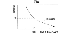
ここでは、上記熱流体解析結果を、横軸を熱伝導率、縦軸を温度としたグラフにプロットし、プロット結果の近似曲線を表す式(近似式)を決定する。図8に、熱伝導率設定値毎の推定温度のプロット結果を示す。ここでは、熱伝導率設定値が5種保持されている場合を例示する。このプロット結果の近似式を近似関数と決定する。 Here, the thermal fluid analysis result is plotted on a graph with the horizontal axis representing thermal conductivity and the vertical axis representing temperature, and an expression (approximate expression) representing an approximate curve of the plotted result is determined. In FIG. 8, the plot result of the estimated temperature for every heat conductivity setting value is shown. Here, a case where five types of thermal conductivity setting values are held is illustrated. The approximate expression of this plot result is determined as an approximate function.
熱伝導率算出部250は、求めた図8の近似曲線f(x)を示す関数に、ステップS1102で実測した温度(T)を代入することにより、測定サンプルの熱伝導率(ここでは、熱伝導率)f(T)を求めることができる。
The
以上説明したように、本実施形態によれば、実測温度とシミュレーション結果とを用いて未知の熱伝導率を算出するにあたり、対流と放射との影響を抑え、伝導が支配的となる環境で温度を実測する。このような環境は、熱流体解析ソフトウェアによるシミュレーションで再現しやすいため、実測環境とシミュレーション環境との乖離による誤差を低減することができる。従って、高い精度で未知の熱伝導率を算出することができる。 As described above, according to this embodiment, in calculating the unknown thermal conductivity using the measured temperature and the simulation result, the influence of convection and radiation is suppressed, and the temperature is controlled in an environment where conduction is dominant. Is actually measured. Such an environment can be easily reproduced by simulation using thermal fluid analysis software, and therefore errors due to the difference between the actual measurement environment and the simulation environment can be reduced. Therefore, the unknown thermal conductivity can be calculated with high accuracy.
また、実測時に用いる温度測定装置110は、簡易で安価な構成である。従って、本実施形態によれば、高価な熱伝導率測定装置を用いることなく、低コストで未知の熱伝導率を精度良く得ることができる。
Further, the
さらに、本実施形態の温度測定装置110は、高価な熱伝導率測定装置に使用される断熱材を使用する必要がないため、環境負荷を少なくすることができる。
Furthermore, since the
なお、本実施形態では、パラメータ決定処理において測定サンプル111の温度測定点の温度を測定しているが、ここで測定を行わず、投入電力決定処理において得た、ヒータ113近傍の測定点の温度を用いるよう構成してもよい。この場合、投入電力決定処理において、測定した温度を測定値保持部310に記憶する。
In the present embodiment, the temperature at the temperature measurement point of the
<<第二の実施形態>>
本発明を適用する第二の実施形態について説明する。本実施形態は、基本的に第一の実施形態と同様である。ただし、第一の実施形態では、温度を実測する温度測定点を1点としたが、本実施形態では、この温度測定点を複数設定する。これにより、求める熱伝導率の精度を向上させる。以下、本実施形態の構成を、第一の実施形態と異なる構成に主眼をおいて説明する。
<< Second Embodiment >>
A second embodiment to which the present invention is applied will be described. This embodiment is basically the same as the first embodiment. However, in the first embodiment, one temperature measurement point for actually measuring the temperature is set as one point, but in this embodiment, a plurality of temperature measurement points are set. Thereby, the accuracy of the required thermal conductivity is improved. Hereinafter, the configuration of the present embodiment will be described focusing on the configuration different from the first embodiment.
本実施形態の熱伝導率算出システム100は、基本的に第一の実施形態と同様の構成を有する。ただし、本実施形態では、測定サンプル111上の複数の点を計測するため、温度測定装置110における熱電対114は、少なくとも温度測定点の数、備える。
The thermal
本実施形態の投入電力決定部210による投入電力決定処理およびパラメータ決定部220によるパラメータ決定処理は、基本的に第一の実施形態と同様である。ただし、本実施形態のパラメータ決定部230は、複数の測定点で温度を測定する。そして、得られた複数の実測温度を、温度測定点に対応づけて測定値保持部310に記憶する。また、放射率は、いずれか一箇所の温度測定点で算出する。
The input power determination process by the input
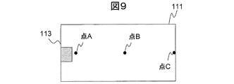
なお、本実施形態では、温度測定点は、2点以上であればよいが、3点以上設定することが望ましい。温度測定点を2点とする場合は、1点を発熱源であるヒータ113の近傍に設定し、他点を、そこから可能な限り距離を置いた位置に設定する。これは、温度測定点間の温度差ができる限り大きい方が測定誤差の影響を相対的に小さくすることができるためである。また、温度測定点を3点以上とする場合は、両端の点を上記のように設定した2点間に残りの点を等間隔で設ける。図9に温度測定点を3点(点A、点B、点C)設ける場合を例示する。
In this embodiment, the temperature measurement points may be two or more, but it is desirable to set three or more. When there are two temperature measurement points, one point is set in the vicinity of the
次に、本実施形態の熱流体解析部230による熱流体解析処理について説明する。本実施形態の熱流体解析部230による熱流体解析処理は、基本的には第一の実施形態と同様である。
Next, thermal fluid analysis processing by the thermal
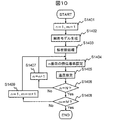
本実施形態の熱流体解析部230による熱流体解析処理の処理フローを図10に示す。ここでは、第一の実施形態と同様にN個(Nは3以上の自然数)の異なる熱伝導率設定値が保持されているものとし、温度測定点はM個(Mは2以上の自然数)とする。
The processing flow of the thermal fluid analysis process by the thermal
まず、カウンタnおよびmを1とする(ステップS1401)。そして、3次元CADにより解析モデルを生成する(ステップS1402)。次に、解析前処理を行う(ステップS1403)。 First, the counters n and m are set to 1 (step S1401). Then, an analysis model is generated by three-dimensional CAD (step S1402). Next, pre-analysis processing is performed (step S1403).
次に、熱伝導率を設定する(ステップS1404)。ここでは、仮設定値保持部320に保持される、n番目の熱伝導率設定値を設定する。
Next, thermal conductivity is set (step S1404). Here, the nth thermal conductivity set value held in the temporary set
そして、熱流体解析ソフトを用い、温度測定点の温度を算出する(ステップS1406)。なお、算出した温度は、推定温度として、温度測定点とステップS1404で設定した熱伝導率設定値とに対応づけて記憶装置に記憶する。 Then, the temperature of the temperature measurement point is calculated using thermal fluid analysis software (step S1406). The calculated temperature is stored in the storage device as the estimated temperature in association with the temperature measurement point and the thermal conductivity setting value set in step S1404.
全ての熱伝導率設定値について処理を終えたか判別し(n=N?)(ステップS1406)。未処理の熱伝導率設定値があれば、nを1インクリメントし(ステップS1407)、ステップS1404に移行し、処理を続ける。 It is determined whether the processing has been completed for all the thermal conductivity setting values (n = N?) (Step S1406). If there is an unprocessed thermal conductivity setting value, n is incremented by 1 (step S1407), the process proceeds to step S1404, and the process is continued.
一方、ステップS1406で、全ての熱伝導率設定値について処理を終えたものと判別された場合、全ての温度測定点について処理を終えたか判別し(m=M?)(ステップS1408)、終えていれば、処理を終了する。一方、未処理の温度測定点があれば、カウンタmを1インクリメントするとともに、カウンタnを1とし(ステップS1409)、ステップS1404に移行し、処理を続ける。 On the other hand, if it is determined in step S1406 that the process has been completed for all the thermal conductivity setting values, it is determined whether the process has been completed for all temperature measurement points (m = M?) (Step S1408). If so, the process ends. On the other hand, if there is an unprocessed temperature measurement point, the counter m is incremented by 1 and the counter n is set to 1 (step S1409), the process proceeds to step S1404, and the process is continued.
以上により、本実施形態の熱流体解析部230は、熱流体解析結果として温度測定点毎に、熱伝導率設定値毎の推定温度を得る。
As described above, the thermal
次に、本実施形態の近似関数作成部240による近似関数作成処理について説明する。近似関数作成処理も基本的に第一の実施形態と同様であるが、本実施形態では、測定点毎に近似関数を作成する。
Next, an approximate function creation process by the approximate
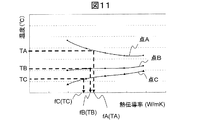
すなわち、本実施形態の近似関数作成部240は、まず、上記熱流体解析結果を、横軸を熱伝導率、縦軸を温度としたグラフにプロットし、温度測定点毎に、プロット結果の近似式を決定する。図11に、温度測定点を3点(点A、点B、点C)とした場合の、熱伝導率設定値毎の推定温度のプロット結果を示す。そして、本実施形態の近似関数作成部240は、このプロット結果から第一の実施形態と同様の手法で、温度測定点毎の近似関数を決定する。ここでは、3つの近似関数が得られる。
That is, the approximate
次に、本実施形態の熱伝導率算出部250による、熱伝導率算出処理について説明する。本実施形態では、複数の近似関数が得られる。各温度測定点の実測温度を、それぞれ、TA、TB、TCとし、図11に示す各温度測定点の近似関数を、それぞれfA(x)、fB(x)、fC(x)とすると(ここで、xは熱伝導率)、各実測温度に対応する熱伝導率は、それぞれ、fA(TA)、fB(TB)、fC(TC)となる。
Next, the thermal conductivity calculation process by the thermal
実測温度に対応する熱伝導率が、各温度測定点について同じとなる場合は、第一の実施形態と同様に、近似関数上で実測温度に対応する熱伝導率を、測定サンプル111の熱伝導率と算出する。すなわち、fA(TA)=fB(TB)=fC(TC)の場合、熱伝導率算出部250は、fA(TA)を熱伝導率とする。
When the thermal conductivity corresponding to the measured temperature is the same for each temperature measurement point, the thermal conductivity corresponding to the measured temperature on the approximate function is the thermal conductivity of the
一方、いずれかの近似関数から算出した実測温度に対応する熱伝導率が異なる場合は、熱伝導率算出部250は、以下の手法で実測温度と推定温度との差異が最小となる熱伝導率を求め、測定サンプル111の熱伝導率とする。具体的な手法を、温度測定点が3点の場合を例にあげて説明する。
On the other hand, when the thermal conductivity corresponding to the measured temperature calculated from any one of the approximate functions is different, the thermal
まず、各温度測定点について、実測温度と、熱伝導率をxとした場合の近似関数から得られる推定温度との差を算出する式FA(x)、FB(x)、FC(x)を求める。ここで、FA(x)、FB(x)、FC(x)は、それぞれ、
FA(x)=TA−fA(x)
FB(x)=TB−fB(x)
FC(x)=TC−fC(x)
と表される。
First, for each temperature measurement point, the formulas FA (x), FB (x), and FC (x) for calculating the difference between the measured temperature and the estimated temperature obtained from the approximate function when the thermal conductivity is x are Ask. Here, FA (x), FB (x), and FC (x) are respectively
FA (x) = TA−fA (x)
FB (x) = TB−fB (x)
FC (x) = TC−fC (x)
It is expressed.
そして、熱伝導率算出部250は、FA(x)、FB(x)、FC(x)の2乗和(G(x)=(FA(x))2+(FB(x))2+(FC(x))2)を最小とするxを算出し、測定サンプルの熱伝導率とする。
Then, the
以上説明したように、本実施形態によれば、第一の実施形態同様の環境で測定サンプル111の温度を実測するとともに熱流体解析ソフトウェアによるシミュレーションを行うため、第一の実施形態と同様の効果を得ることができる。
As described above, according to the present embodiment, the temperature of the
さらに、本実施形態によれば、複数の温度測定点で測定した実測温度を用い、熱伝導率を算出している。測定サンプル111全体の測定数を増やすことにより、算出結果について測定誤差の影響を小さくすることができるため、本実施形態によれば、より高い精度で測定サンプル111の熱伝導率を得ることができる。
Furthermore, according to the present embodiment, the thermal conductivity is calculated using measured temperatures measured at a plurality of temperature measurement points. Since the influence of the measurement error on the calculation result can be reduced by increasing the number of measurements of the
本実施形態においても、投入電力決定処理において温度を測定する測定点の数と、温度測定点の数とが同じであれば、第一の実施形態と同様、パラメータ決定処理において改めて測定点の温度を測定せず、投入電力決定処理において測定した温度を用いるよう構成してもよい。 Also in this embodiment, if the number of measurement points for measuring the temperature in the input power determination process is the same as the number of temperature measurement points, the temperature of the measurement point is again determined in the parameter determination process as in the first embodiment. The temperature measured in the input power determination process may be used without measuring the power.
なお、熱伝導率算出処理において、実測温度に対応する熱伝導率が近似関数毎に異なる場合の処理は、上記手法に限られない。例えば、各温度測定点について得られた熱伝導率の平均を、測定サンプル111の熱伝導率と算出してもよい。
In the thermal conductivity calculation process, the process when the thermal conductivity corresponding to the actually measured temperature is different for each approximate function is not limited to the above method. For example, the average of the thermal conductivity obtained for each temperature measurement point may be calculated as the thermal conductivity of the
<<第三の実施形態>>
本発明を適用する第三の実施形態について説明する。本実施形態は、基本的に第二の実施形態と同様である。ただし、第二の実施形態では、温度測定点毎に、実測温度および推定温度をそのまま用いて熱伝導率を算出しているが、本実施形態では、各温度測定点間の温度差を用いて熱伝導率を算出する。これにより、求められる熱伝導率の精度を向上させる。以下、本実施形態の構成を、第二の実施形態と異なる構成に主眼をおいて説明する。
<< Third Embodiment >>
A third embodiment to which the present invention is applied will be described. This embodiment is basically the same as the second embodiment. However, in the second embodiment, the thermal conductivity is calculated by using the measured temperature and the estimated temperature as they are for each temperature measurement point, but in this embodiment, the temperature difference between each temperature measurement point is used. Calculate the thermal conductivity. This improves the accuracy of the required thermal conductivity. Hereinafter, the configuration of the present embodiment will be described focusing on the configuration different from the second embodiment.
本実施形態の熱伝導率算出システム100は、第二の実施形態と基本的に同様の構成を有する。すなわち、第二の実施形態と同様の手法で投入電力を決定し、同様の手法で熱流体解析結果を得る。ただし、上述のように、本実施形態では、熱伝導率を算出するにあたり、各測定点間の温度差を用いるため、近似関数作成処理が異なる。
The thermal
本実施形態の近似関数作成部240による近似関数作成処理について説明する。本実施形態の近似関数作成部240は、記憶装置に保持される熱流体解析結果で得た温度測定点毎の推定温度から、熱伝導率毎に、各温度測定点間の推定温度差を算出する。推定温度差は、温度測定点の全組合せについて算出する。
An approximate function creation process by the approximate
例えば、第二の実施形態のように、温度測定点が3点(点A、点B、点C)の場合、点Aと点Bとの間の推定温度差tAB、点Aと点Cとの間の推定温度差tAC、点Bと点Cとの間の推定温度差tBCを算出する。なお、各温度測定点の推定温度をそれぞれtA、tB、tCとすると、それぞれ、tAB=tA−tB、tAC=tA−tC、tBC=tB−tCである。 For example, as in the second embodiment, when there are three temperature measurement points (point A, point B, and point C), the estimated temperature difference tAB between point A and point B, point A and point C, Is estimated temperature difference tAC, and estimated temperature difference tBC between points B and C is calculated. If the estimated temperatures at the temperature measurement points are tA, tB, and tC, respectively, tAB = tA−tB, tAC = tA−tC, and tBC = tB−tC.
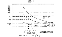
得られた各温度差を、温度測定点間毎に、横軸を熱伝導率、縦軸を温度差とするグラフにプロットし、プロット結果の近似式を決定する。図12に、温度測定点が3点の場合の、熱伝導率設定値毎の推定温度の温度差のプロット結果を示す。本実施形態においても、熱伝導率設定値は5種保持されている場合を例示する。近似関数作成部240は、上記各実施形態同様の手法で、このプロット結果の近似式を算出し、温度測定点間毎の近似関数と決定する。
Each obtained temperature difference is plotted on a graph with the horizontal axis representing the thermal conductivity and the vertical axis representing the temperature difference for each temperature measurement point, and an approximate expression of the plotted result is determined. In FIG. 12, the plot result of the temperature difference of the estimated temperature for every thermal conductivity setting value in the case of three temperature measurement points is shown. Also in this embodiment, the case where five types of thermal conductivity setting values are held is illustrated. The approximate
次に、本実施形態の熱伝導率算出部250による熱伝導率算出処理について説明する。本実施形態では、各温度測定点間の実測温度差と推定温度差から得た複数の近似関数とから熱伝導率を推定する。
Next, the thermal conductivity calculation process by the thermal
例えば、温度測定点が点Aおよび点Cの2点の場合、得られる近似関数は1つである。従って、熱伝導率算出部250は、第一の実施形態同様、この近似関数上で、実測温度の温度差に対応する熱伝導率を、測定サンプル111の熱伝導率とする。
For example, when there are two temperature measurement points, point A and point C, one approximate function is obtained. Therefore, as in the first embodiment, the thermal
一方、温度測定点が3点(点A、点B、点C)の場合は、まず、各温度測定点間の実測温度差を算出する。各温度測定点の実測温度をそれぞれTA、TB、TCとすると、点Aと点Bとの間の実測温度差TABはTA−TB、点Aと点Cとの間の実測温度差TACは、TA−TC、点Bと点Cとの間の実測温度差TBCは、TB−TCと求められる。ここで、図12に示す、各測定点の温度差と熱伝導率設定値との関係から算出された近似関数を、それぞれfAB(x)、fAC(x)、fBC(x)とすると(ここで、xは熱伝導率)、各温度測定点間の実測温度差に対応する熱伝導率は、それぞれ、fAC(TAC)、fAB(TAB)、fBC(TBC)となる。 On the other hand, when there are three temperature measurement points (point A, point B, and point C), first, an actually measured temperature difference between the temperature measurement points is calculated. If the measured temperatures at each temperature measurement point are TA, TB, and TC, respectively, the measured temperature difference TAB between point A and point B is TA-TB, and the measured temperature difference TAC between point A and point C is TA-TC, the measured temperature difference TBC between point B and point C is obtained as TB-TC. Here, if the approximate functions calculated from the relationship between the temperature difference at each measurement point and the thermal conductivity setting value shown in FIG. 12 are fAB (x), fAC (x), and fBC (x), respectively (here And x is the thermal conductivity), and the thermal conductivities corresponding to the actually measured temperature differences between the temperature measurement points are fAC (TAC), fAB (TAB), and fBC (TBC), respectively.
第二の実施形態同様、各温度測定点間の実測温度差に対応する熱伝導率が、各近似関数で同じとなる場合は、第二の実施形態と同様、近似関数上で実測温度差に対応する熱伝導率を、測定サンプルの熱伝導率とする。すなわち、fAC(TAC)=fAB(TAB)=fBC(TBC)の場合、熱伝導率算出部250は、fAC(TAC)を熱伝導率とする。
As in the second embodiment, when the thermal conductivity corresponding to the measured temperature difference between each temperature measurement point is the same in each approximate function, the measured temperature difference is calculated on the approximate function as in the second embodiment. The corresponding thermal conductivity is taken as the thermal conductivity of the measurement sample. That is, when fAC (TAC) = fAB (TAB) = fBC (TBC), the thermal
一方、実測温度差に対応する熱伝導率が、近似関数毎に異なる場合は、熱伝導率算出部250は、以下の手法で、実測温度差と推定温度差との差異が最小となる熱伝導率を求め、測定サンプル111の熱伝導率とする。
On the other hand, when the thermal conductivity corresponding to the measured temperature difference is different for each approximate function, the thermal
まず、各温度測定点間について、実測温度差と、熱伝導率がxの場合の近似関数から得られる推定温度差との差を算出する式FAB(x)、FAC(x)、FBC(x)を求める。式FAB(x)、FAC(x)、FBC(x)は、それぞれ、
FAB(x)=TAB−fAB(x)
FAC(x)=TAC−fAC(x)
FBC(x)=TBC−fBC(x)
となる。
First, for each temperature measurement point, the formulas FAB (x), FAC (x), FBC (x) for calculating the difference between the measured temperature difference and the estimated temperature difference obtained from the approximate function when the thermal conductivity is x. ) The formulas FAB (x), FAC (x) and FBC (x) are respectively
FAB (x) = TAB−fAB (x)
FAC (x) = TAC-fAC (x)
FBC (x) = TBC-fBC (x)
It becomes.
そして、熱伝導率算出部250は、FAB(x)、FAC(x)、FBC(x)の2乗和(GG(x)=(FAB(x))2+(FAC(x))2+(FBC(x))2)を最小とするxを計算し、測定サンプル111の熱伝導率とする。
Then, the
以上説明したように、本実施形態によれば、上記各実施形態同様の環境で測定サンプル111の温度を実測するとともに熱流体解析ソフトウェアによるシミュレーションを行うため、上記各実施形態と同様の効果を得ることができる。
As described above, according to the present embodiment, the temperature of the
また、本実施形態によれば、近似関数を複数の温度測定点の推定温度について、温度測定点間の温度差から決定し、熱伝導率を、この温度差と複数の温度測定点で測定した実測温度の温度測定点間の温度差とを用いて算出する。これにより、よりシミュレーション結果と実測との差異を小さくすることが出来、得られる熱伝導率の精度も高まる。 Further, according to the present embodiment, the approximate function is determined from the temperature difference between the temperature measurement points for the estimated temperature at the plurality of temperature measurement points, and the thermal conductivity is measured at the temperature difference and the plurality of temperature measurement points. It calculates using the temperature difference between the temperature measurement points of actual measurement temperature. Thereby, the difference between the simulation result and the actual measurement can be further reduced, and the accuracy of the obtained thermal conductivity is increased.
一般に、熱流体解析ソフトによるシミュレーション結果と実測結果との差異を熱伝導率が算出できる程度(±5℃以内)に抑えることは非常に困難であることが知られている。このようなシミュレーション結果と実測結果との乖離は、対流と放射のパラメータに起因すると考えられる。一方、部材内部の熱移動である熱伝導は両結果に影響を与えにくいパラメータである。そこで、本実施形態のように、温度の絶対値ではなく温度差(測定サンプル111内部の熱伝導)を用い、近似曲線の決定、および、この近似曲線と実測値による熱伝導率の算出を行うと、実測結果とシミュレーション結果との誤差が少ない状態で熱伝導率を算出することができる。このため、高い精度で熱伝導率の算出を行うことができる。 In general, it is known that it is very difficult to suppress the difference between the simulation result by the thermal fluid analysis software and the actual measurement result to such an extent that the thermal conductivity can be calculated (within ± 5 ° C.). Such a difference between the simulation result and the actual measurement result is considered to be caused by parameters of convection and radiation. On the other hand, heat conduction, which is heat transfer inside the member, is a parameter that hardly affects both results. Therefore, as in the present embodiment, not the absolute value of the temperature but the temperature difference (heat conduction inside the measurement sample 111) is used to determine the approximate curve and calculate the thermal conductivity based on the approximate curve and the actually measured value. The thermal conductivity can be calculated in a state where there is little error between the actual measurement result and the simulation result. For this reason, it is possible to calculate the thermal conductivity with high accuracy.
なお、熱伝導率算出処理において、実測温度に対応する熱伝導率が近似関数毎に異なる場合の処理は、上記手法に限られない。例えば、各温度測定点について得られた熱伝導率の平均を、測定サンプル111の熱伝導率と算出してもよい。
In the thermal conductivity calculation process, the process when the thermal conductivity corresponding to the actually measured temperature is different for each approximate function is not limited to the above method. For example, the average of the thermal conductivity obtained for each temperature measurement point may be calculated as the thermal conductivity of the
本実施形態においても、投入電力決定処理において温度を測定する測定点の数と、温度測定点の数とが同じであれば、第一の実施形態と同様、パラメータ決定処理において改めて測定点の温度を測定せず、投入電力決定処理において測定した温度を用いるよう構成してもよい。 Also in this embodiment, if the number of measurement points for measuring the temperature in the input power determination process is the same as the number of temperature measurement points, the temperature of the measurement point is again determined in the parameter determination process as in the first embodiment. The temperature measured in the input power determination process may be used without measuring the power.
<<実施例1>>
以下、本発明の実施例を示す。まず、第一および第二の実施形態の実施例を示す。ここでは、100mm角×1mmの銅平板(390W/mK)と150mm×50mm×50mmのアルミ合金(170W/mK)の成型品を被測定物(測定サンプル)111とし、投入電力は測定点の温度差が2℃となる2Wとした。また、熱伝導率設定値として、200W/mK、300W/mK、400W/mK、500W/mK、600W/mKの5種を用いた。また、温度測定点は、図9に示す3点(それぞれ、A点、B点、C点)とした。熱流体解析ソフトウェアとして、CFdesign(登録商標)を用いた。
<< Example 1 >>
Examples of the present invention will be described below. First, examples of the first and second embodiments will be described. Here, a molded product of a 100 mm square × 1 mm copper flat plate (390 W / mK) and a 150 mm × 50 mm × 50 mm aluminum alloy (170 W / mK) is used as an object to be measured (measurement sample) 111, and the input power is the temperature at the measurement point. The difference was 2 W at 2 ° C. Further, five types of heat conductivity set values of 200 W / mK, 300 W / mK, 400 W / mK, 500 W / mK, and 600 W / mK were used. The temperature measurement points were three points shown in FIG. 9 (points A, B, and C, respectively). CFdesign (registered trademark) was used as thermal fluid analysis software.
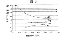
図13は、上記第二の実施形態の手法に従って、熱伝導率算出処理を行い、シミュレートして得た熱伝導率設定値毎の推定温度を、温度測定点毎にフィッティングした近似曲線のグラフである。 FIG. 13 is a graph of an approximate curve obtained by fitting the estimated temperature for each thermal conductivity set value obtained by performing thermal conductivity calculation processing and simulating according to the method of the second embodiment, for each temperature measurement point. It is.
このとき、温度測定点Aでの実測温度は、46.9℃であった。また、測定点Bでの実測温度は、45.7℃であり、測定点Cでの実測温度は、45.2℃であった。図13のグラフから測定サンプル111の熱伝導率として、発熱源近傍の温度測定点Aによる結果から、約62.5W/mKを得た。ここでは、熱伝導率の公表値が390W/mKといった高い熱伝導率を有するアルミ合金による成型品を用いたが、熱伝導率が10W/mK程度と低い高熱伝導樹脂などでは、第一および第二の実施形態の温度による熱伝導率推定の精度はさらに高まる。
At this time, the actually measured temperature at the temperature measuring point A was 46.9 ° C. Further, the actual temperature at the measurement point B was 45.7 ° C., and the actual temperature at the measurement point C was 45.2 ° C. From the result of the temperature measurement point A in the vicinity of the heat source, about 62.5 W / mK was obtained as the thermal conductivity of the
<<実施例2>>
次に、第三の実施形態の実施例を示す。測定サンプル111、投入電力、用いた熱伝導率設定値、温度測定点、使用した熱流体解析ソフトウェアは、上記実施例1と同じとした。
<< Example 2 >>
Next, an example of the third embodiment will be described. The
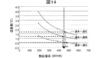
図14は、上記第三の実施形態の手法に従って、熱伝導率算出処理を行い、シミュレートして得た熱伝導率設定値毎の、A点とB点との推定温度差、A点とC点との推定温度差、B点とC点との推定温度差それぞれの近似曲線のグラフである。 FIG. 14 shows an estimated temperature difference between point A and point B for each thermal conductivity setting value obtained by performing thermal conductivity calculation processing and simulating according to the method of the third embodiment, It is a graph of the approximate curve of each estimated temperature difference with C point, and each estimated temperature difference with B point and C point.
各点の実測温度は、上記第二の実施例のとおりである。従って、測定サンプル111の熱伝導率として、456W/mKを得る。この値は公表値390W/mKと17%の差異となり、測定対象が高い熱伝導率を有する場合であっても、実施例1よりもさらに精度良く測定できることが分かる。
The measured temperature at each point is as in the second embodiment. Therefore, 456 W / mK is obtained as the thermal conductivity of the
11:測定点、12:測定点、100:熱伝導率算出システム、110:温度測定装置、111:測定サンプル、112:樹脂ケース、113:ヒータ、114:熱電対、115:放射温度計、120:熱伝導率算出装置、210:投入電力決定部、220:パラメータ決定部、230:熱流体解析部、240:近似関数作成部、250:熱伝導率算出部、310:測定値保持部、320:仮設定値保持部 11: measurement point, 12: measurement point, 100: thermal conductivity calculation system, 110: temperature measurement device, 111: measurement sample, 112: resin case, 113: heater, 114: thermocouple, 115: radiation thermometer, 120 : Thermal conductivity calculation device, 210: input power determination unit, 220: parameter determination unit, 230: thermal fluid analysis unit, 240: approximate function creation unit, 250: thermal conductivity calculation unit, 310: measurement value holding unit, 320 : Temporary set value holding section
Claims (11)
前記測定サンプルに熱を供給する発熱体に投入する電力を決定する投入電力決定ステップと、
前記発熱体に前記投入電力を投入して発熱させた際の前記測定サンプルの温度を、予め定めた測定点において測定し、実測温度を得る温度測定ステップと、
予め定められた複数の熱伝導率設定値それぞれに対応する前記測定サンプルの温度を推定温度として算出する温度推定ステップと、
前記複数の熱伝導率設定値毎の前記推定温度から熱伝導率と推定温度とを関連付ける近似関数を決定する近似関数算出ステップと、
前記近似関数上で、前記実測温度を用い、当該測定サンプルの熱伝導率を算出する熱伝導率算出ステップと、を備えること
を特徴とする熱伝導率算出方法。 A thermal conductivity calculation method for calculating the thermal conductivity of a measurement sample,
An input power determination step for determining power to be input to a heating element that supplies heat to the measurement sample;
A temperature measurement step of measuring the temperature of the measurement sample when the input power is supplied to the heating element and generating heat, at a predetermined measurement point, and obtaining an actual temperature;
A temperature estimation step of calculating the temperature of the measurement sample corresponding to each of a plurality of predetermined thermal conductivity setting values as an estimated temperature;
An approximate function calculating step for determining an approximate function for associating the thermal conductivity with the estimated temperature from the estimated temperature for each of the plurality of thermal conductivity setting values;
A thermal conductivity calculation step of calculating the thermal conductivity of the measurement sample using the measured temperature on the approximate function.
前記熱伝導率算出ステップでは、前記近似関数上で前記実測温度に対応する熱伝導率を当該測定サンプルの熱伝導率とすること
を特徴とする熱伝導率算出方法。 The thermal conductivity calculation method according to claim 1,
In the thermal conductivity calculation step, the thermal conductivity corresponding to the measured temperature on the approximate function is set as the thermal conductivity of the measurement sample.
前記温度測定ステップで前記実測温度を得る測定点は複数であり、
前記温度推定ステップでは、前記複数の測定点それぞれの推定温度を算出し、
前記近似関数算出ステップでは、前記複数の測定点それぞれについて前記近似関数を決定し、
前記熱伝導率算出ステップでは、前記測定点毎の近似関数上で、前記実測温度を用い、当該測定サンプルの熱伝導率を算出すること
を特徴とする熱伝導率算出方法。 The thermal conductivity calculation method according to claim 1,
There are a plurality of measurement points for obtaining the actual temperature in the temperature measurement step,
In the temperature estimation step, an estimated temperature of each of the plurality of measurement points is calculated,
In the approximate function calculating step, the approximate function is determined for each of the plurality of measurement points,
In the thermal conductivity calculation step, the thermal conductivity of the measurement sample is calculated using the measured temperature on the approximate function for each measurement point.
前記熱伝導率算出ステップでは、前記複数の測定点それぞれについて求めた前記近似関数上で熱伝導率に対応する近似温度と実測温度との差の2乗和が最小となる熱伝導率を、当該測定サンプルの熱伝導率とすること
を特徴とする熱伝導率算出方法。 The thermal conductivity calculation method according to claim 3,
In the thermal conductivity calculation step, the thermal conductivity that minimizes the sum of squares of the difference between the approximate temperature corresponding to the thermal conductivity and the actually measured temperature on the approximate function obtained for each of the plurality of measurement points is A method for calculating thermal conductivity, characterized in that the thermal conductivity of a measurement sample is used.
前記温度測定ステップが前記実測温度を得る測定点は複数であり、
前記温度推定ステップでは、前記複数の測定点それぞれの推定温度を算出し、
前記近似関数算出ステップでは、前記複数の測定点間の推定温度の差である推定温度差を算出し、当該測定点間毎に前記近似関数を熱伝導率と推定温度差とを関連付ける関数として決定し、
前記熱伝導率算出ステップでは、前記複数の測定点間の実測温度の差である実測温度差を算出し、前記測定点間毎の近似関数上で、前記実測温度差を用い、当該測定サンプルの熱伝導率を算出すること
を特徴とする熱伝導率算出方法。 The thermal conductivity calculation method according to claim 1,
The temperature measurement step has a plurality of measurement points to obtain the actual temperature,
In the temperature estimation step, an estimated temperature of each of the plurality of measurement points is calculated,
In the approximate function calculating step, an estimated temperature difference that is an estimated temperature difference between the plurality of measurement points is calculated, and the approximate function is determined as a function that associates thermal conductivity and the estimated temperature difference between the measurement points. And
In the thermal conductivity calculation step, an actual temperature difference that is a difference in actual temperature between the plurality of measurement points is calculated, and the actual temperature difference of the measurement sample is calculated using the actual temperature difference on an approximate function between the measurement points. A method for calculating thermal conductivity, comprising calculating thermal conductivity.
前記温度測定ステップが前記実測温度を得る測定点は3以上であり、
前記熱伝導率算出ステップでは、前記複数の測定点間それぞれについて求めた前記近似関数上で熱伝導率に対応する近似温度差と実測温度差との差の2乗和が最小となる熱伝導率を、当該測定サンプルの熱伝導率とすること
を特徴とする熱伝導率算出方法。 The thermal conductivity calculation method according to claim 5,
The measurement point at which the temperature measurement step obtains the actual temperature is 3 or more,
In the thermal conductivity calculation step, the thermal conductivity that minimizes the sum of squares of the difference between the approximate temperature difference corresponding to the thermal conductivity and the measured temperature difference on the approximate function obtained for each of the plurality of measurement points. Is defined as the thermal conductivity of the measurement sample.
前記投入電力決定ステップでは、前記測定サンプル上の、前記発熱体に最も近い位置と最も離れた位置との温度差が所定以上となる電力であって、最小の電力を、前記投入電力と決定すること
を特徴とする熱伝導率算出方法。 The thermal conductivity calculation method according to claim 1, wherein:
In the input power determination step, the minimum power is determined as the input power, which is a power at which a temperature difference between a position closest to the heating element and a position farthest from the heating element on the measurement sample is a predetermined value or more. The thermal conductivity calculation method characterized by this.
前記温度測定ステップ直後に前記測定サンプルの表面の放射率を算出する放射率算出手段をさらに備え、
前記温度推定ステップでは、前記放射率も加味し、前記推定温度を算出すること
を特徴とする熱伝導率算出方法。 The thermal conductivity calculation method according to claim 1, wherein
An emissivity calculating means for calculating the emissivity of the surface of the measurement sample immediately after the temperature measuring step;
In the temperature estimation step, the estimated temperature is calculated in consideration of the emissivity.
前記温度推定ステップでは、熱流体解析ソフトウェアを用い、前記推定温度を算出すること
を特徴とする熱伝導率算出方法。 A thermal conductivity calculation method according to any one of claims 1 to 8,
In the temperature estimation step, the estimated temperature is calculated using thermal fluid analysis software.
前記測定サンプルに熱を供給する発熱体に投入する投入電力を決定する投入電力決定手段と、
前記発熱体に前記電力を投入して発熱させた際の前記測定サンプルの温度を、予め定めた測定点において測定し、実測温度を得る温度測定手段と、
予め定められた複数の熱伝導率設定値それぞれに対応する前記測定サンプルの温度を推定温度として算出する温度推定手段と、
前記複数の熱伝導率設定値毎の前記推定温度から熱伝導率と推定温度とを関連付ける近似関数を決定する近似関数算出手段と、
前記近似関数上で、前記実測温度を用い、当該測定サンプルの熱伝導率を算出する熱伝導率算出手段と、を備えること
を特徴とする熱伝導率算出システム。 A thermal conductivity calculation system for calculating an unknown thermal conductivity of a measurement sample,
Input power determining means for determining input power to be input to a heating element for supplying heat to the measurement sample;
Temperature measurement means for measuring the temperature of the measurement sample when the power is applied to the heating element to generate heat, and measuring the temperature at a predetermined measurement point;
Temperature estimation means for calculating the temperature of the measurement sample corresponding to each of a plurality of predetermined thermal conductivity setting values as an estimated temperature;
An approximate function calculating means for determining an approximate function for associating the thermal conductivity with the estimated temperature from the estimated temperature for each of the plurality of thermal conductivity setting values;
And a thermal conductivity calculating means for calculating the thermal conductivity of the measurement sample using the measured temperature on the approximate function.
測定サンプルに熱を供給する発熱体に投入する投入電力を決定する投入電力決定手段と、
前記発熱体に前記電力を投入して発熱させた際の前記測定サンプルの温度を、予め定めた測定点において測定し、実測温度を得る温度測定手段と、
測定サンプルの未知の熱伝導率の、予め定められた複数の設定値それぞれに対応する前記測定サンプルの温度を推定温度として算出する温度推定手段と、
前記複数の設定値毎の前記推定温度から熱伝導率と推定温度とを関連付ける近似関数を決定する近似関数算出手段と、
前記近似関数上で、前記実測温度を用い、当該測定サンプルの熱伝導率を算出する熱伝導率算出手段として機能させるためのプログラム。 Computer
Input power determining means for determining input power to be input to a heating element that supplies heat to the measurement sample;
Temperature measurement means for measuring the temperature of the measurement sample when the power is applied to the heating element to generate heat, and measuring the temperature at a predetermined measurement point;
Temperature estimation means for calculating the temperature of the measurement sample corresponding to each of a plurality of predetermined set values of unknown thermal conductivity of the measurement sample as an estimated temperature;
An approximate function calculating means for determining an approximate function that associates thermal conductivity and estimated temperature from the estimated temperature for each of the plurality of set values;
A program for functioning as thermal conductivity calculation means for calculating the thermal conductivity of the measurement sample using the measured temperature on the approximate function.
Priority Applications (1)
| Application Number | Priority Date | Filing Date | Title |
|---|---|---|---|
| JP2009261001A JP2011106918A (en) | 2009-11-16 | 2009-11-16 | Method and system for calculating heat conductivity |
Applications Claiming Priority (1)
| Application Number | Priority Date | Filing Date | Title |
|---|---|---|---|
| JP2009261001A JP2011106918A (en) | 2009-11-16 | 2009-11-16 | Method and system for calculating heat conductivity |
Publications (1)
| Publication Number | Publication Date |
|---|---|
| JP2011106918A true JP2011106918A (en) | 2011-06-02 |
Family
ID=44230567
Family Applications (1)
| Application Number | Title | Priority Date | Filing Date |
|---|---|---|---|
| JP2009261001A Withdrawn JP2011106918A (en) | 2009-11-16 | 2009-11-16 | Method and system for calculating heat conductivity |
Country Status (1)
| Country | Link |
|---|---|
| JP (1) | JP2011106918A (en) |
Cited By (7)
| Publication number | Priority date | Publication date | Assignee | Title |
|---|---|---|---|---|
| JP2014040171A (en) * | 2012-08-22 | 2014-03-06 | Toshiba Corp | Brake incompatibility detection device and brake incompatibility detection method |
| KR101418549B1 (en) | 2012-05-23 | 2014-07-11 | 이재정 | Diagnosis method of breast cancer |
| JP2015502548A (en) * | 2011-12-21 | 2015-01-22 | インスティテュート ドゥ ラディオプロテクション エ ドゥ シュルテ ヌクレア | Process for estimating thermophysical value of material, measurement process including the estimation process, and self-adjusting flow meter |
| JP2015078903A (en) * | 2013-10-17 | 2015-04-23 | 株式会社デンソー | Parameter setting method and simulation apparatus |
| JP2017015530A (en) * | 2015-06-30 | 2017-01-19 | 大和ハウス工業株式会社 | Heat conductivity calculation device, temperature prediction device, computer program, heat conductivity calculation method, and temperature prediction method |
| CN111443106A (en) * | 2020-05-15 | 2020-07-24 | 中南大学 | Test method and system for equivalent thermal conductivity of heterogeneous materials |
| KR20210084616A (en) * | 2018-11-28 | 2021-07-07 | 가부시키가이샤 사무코 | A method for estimating thermal conductivity, a device for estimating thermal conductivity, a method for manufacturing a semiconductor crystal product, a device for calculating thermal conductivity, a computer-readable recording medium in which a program for calculating thermal conductivity is recorded, and a method for calculating thermal conductivity |
-
2009
- 2009-11-16 JP JP2009261001A patent/JP2011106918A/en not_active Withdrawn
Cited By (10)
| Publication number | Priority date | Publication date | Assignee | Title |
|---|---|---|---|---|
| JP2015502548A (en) * | 2011-12-21 | 2015-01-22 | インスティテュート ドゥ ラディオプロテクション エ ドゥ シュルテ ヌクレア | Process for estimating thermophysical value of material, measurement process including the estimation process, and self-adjusting flow meter |
| KR101418549B1 (en) | 2012-05-23 | 2014-07-11 | 이재정 | Diagnosis method of breast cancer |
| JP2014040171A (en) * | 2012-08-22 | 2014-03-06 | Toshiba Corp | Brake incompatibility detection device and brake incompatibility detection method |
| JP2015078903A (en) * | 2013-10-17 | 2015-04-23 | 株式会社デンソー | Parameter setting method and simulation apparatus |
| JP2017015530A (en) * | 2015-06-30 | 2017-01-19 | 大和ハウス工業株式会社 | Heat conductivity calculation device, temperature prediction device, computer program, heat conductivity calculation method, and temperature prediction method |
| KR20210084616A (en) * | 2018-11-28 | 2021-07-07 | 가부시키가이샤 사무코 | A method for estimating thermal conductivity, a device for estimating thermal conductivity, a method for manufacturing a semiconductor crystal product, a device for calculating thermal conductivity, a computer-readable recording medium in which a program for calculating thermal conductivity is recorded, and a method for calculating thermal conductivity |
| KR102556434B1 (en) | 2018-11-28 | 2023-07-14 | 가부시키가이샤 사무코 | Method for estimating thermal conductivity, apparatus for estimating thermal conductivity, method for manufacturing a semiconductor crystal product, apparatus for calculating thermal conductivity, computer readable recording medium having a thermal conductivity calculation program recorded thereon, and method for calculating thermal conductivity |
| US12099026B2 (en) | 2018-11-28 | 2024-09-24 | Sumco Corporation | Thermal conductivity estimation method, thermal conductivity estimation apparatus, production method for semiconductor crystal product, thermal conductivity calculator, thermal conductivity calculation program, and, thermal conductivity calculation method |
| CN111443106A (en) * | 2020-05-15 | 2020-07-24 | 中南大学 | Test method and system for equivalent thermal conductivity of heterogeneous materials |
| CN111443106B (en) * | 2020-05-15 | 2023-02-21 | 中南大学 | Method and system for testing equivalent thermal conductivity coefficient of heterogeneous material |
Similar Documents
| Publication | Publication Date | Title |
|---|---|---|
| Wu et al. | Thermal design for the pouch-type large-format lithium-ion batteries: I. Thermo-electrical modeling and origins of temperature non-uniformity | |
| JP2011106918A (en) | Method and system for calculating heat conductivity | |
| CN116050261A (en) | Oil-immersed transformer hot spot temperature prediction method, system, equipment and storage medium | |
| JP7316855B2 (en) | Temperature distribution estimation device and temperature distribution estimation method | |
| Patil et al. | Inverse determination of temperature distribution in partially cooled heat generating cylinder | |
| CN117951929A (en) | Insulator thermal stress calculation method, device and program product based on temperature rise characteristics | |
| CN112784463A (en) | Internal temperature simulation method for in-well gravimeter system | |
| CN120371054A (en) | Temperature control management method of electric oven | |
| CN120493798A (en) | Axial flux motor temperature prediction method based on equivalent thermal path method calculation | |
| CN117648790A (en) | A temperature analysis method for water-cooled battery packs | |
| JP2015078903A (en) | Parameter setting method and simulation apparatus | |
| Woolley et al. | Thermocouple data in the inverse heat conduction problem | |
| JP2005140693A (en) | Thermophysical property identification method and identification apparatus | |
| CN108519406B (en) | A calculation method of conductor thermal resistance and convection thermal resistance in the axial direction of overhead ground wire | |
| Jeng et al. | Fast numerical algorithm for optimization mold shape of direct injection molding process | |
| JP2009048505A (en) | Circuit operation verification apparatus, circuit operation verification method, semiconductor integrated circuit manufacturing method, control program, and computer-readable readable storage medium | |
| US20240220849A1 (en) | Thermal predictive modeling of physical assets | |
| CN118657013A (en) | Electronic device heat dissipation performance evaluation method and related device | |
| CN118965464A (en) | A method and device for determining thermal physical property parameters of a battery cell | |
| CN111159936A (en) | A Calculation Method for Thermal Field of Cable Joint Based on Generalized Time Domain Finite Difference | |
| CN120409287B (en) | Metal melt resistivity test method for recognizing metal liquid structure | |
| CN109446712B (en) | Temperature calculation method and device | |
| Choi et al. | Inverse design of glass forming process simulation using an optimization technique and distributed computing | |
| Silveira et al. | Estimation of heat generation in semiconductors by inverse heat transfer analysis | |
| CN109682489B (en) | Thermistor type selection method and device based on protection characteristics of electric energy meter |
Legal Events
| Date | Code | Title | Description |
|---|---|---|---|
| A300 | Withdrawal of application because of no request for examination |
Free format text: JAPANESE INTERMEDIATE CODE: A300 Effective date: 20130205 |